1. Introduction
The era of optical information demands the establishment of communication network systems with high transmission rates, large data capacities, and extensive coverage. Utilizing optical waves with extremely short wavelengths for space-based satellite communication is the optimal solution to achieve high data-rate communication, particularly in today’s context where the microwave frequency spectrum is limited and space resources are increasingly crowded [
1,
2]. Companies like Starlink in the United States and OneWeb in the United Kingdom have already planned or launched massive satellite constellations, with inter-satellite communications relying on laser links for information transmission [
3].
With the rapid advancement of information technology, the demand for multi-dimensional, integrated information resources in future information services is increasing. Strategic information services in national security, aerospace, environmental monitoring, traffic management, education and healthcare, industrial and agricultural sectors, counter-terrorism, and disaster relief will unfold in a multi-dimensional space encompassing the air, space, and ground. Information utilization within a single dimension cannot meet these comprehensive needs [
4,
5,
6]. Therefore, the development of space-based local area network (LAN) optical communication technology has become an inevitable trend in the evolution of optical communication [
7,
8,
9].
The future trend of space optical communication is to achieve longer distances, higher communication rates, and lower power consumption. To accomplish this, the divergence angle of the laser beam must be compressed to the order of tens of micro-arcseconds [
10]. Consequently, rapid capture and stable maintenance of the laser link become crucial [
11,
12]. Even minor misalignment errors can cause a decline in the communication link performance and result in significant loss of system efficiency [
13].
Optical communication, due to its advantages such as easy terminal deployment and high transmission rates, is currently the best solution for achieving high-rate communication in space. However, space optical communication relies on small divergence angle beams to provide high transmit and receive gains. This imposes stricter requirements on the speed and stability of laser beam acquisition and tracking than traditional microwave communication systems. Small divergence angles, low calibration accuracy, platform attitude drift, and micro-vibrations pose significant challenges to the scanning, acquisition, and alignment of laser beams [
14,
15,
16].
In this work, space optical networks specifically refer to inter-satellite or satellite-to-ground laser communication systems operating in the vacuum or near-vacuum conditions of outer space. This is distinguished from terrestrial free-space optical (FSO) communication, which operates within Earth’s atmosphere and must account for turbulence, aerosol scattering, and weather-related attenuation. While both domains utilize optical wireless transmission, their technical challenges diverge fundamentally.
This paper primarily focuses on the research of rapid ground-based laser link establishment technologies. It explores methods to achieve fast deployment and link establishment for optical communication pointing, acquisition, and tracking (PAT) terminals and conducts targeted analytical and verification work to solve the challenges of rapid switching and long-term high-stability maintenance in space-based LAN laser networks. By studying the mechanisms of laser rapid link establishment and the coupling transmission of platform disturbances, this paper aims to provide a basis for the rapid deployment of three-dimensional space LANs and the isolation of beam disturbances using both active and passive methods. This research is significant for improving the overall performance of space optical networks and can be extended to the construction and application of space-based information networks in the future.
2. System Configuration
As shown in
Figure 1, two laser terminals were deployed on opposite shores of Qinghai Lake, separated by over 100 km. The link was established using custom-designed optical communication terminals with a stare-scan acquisition strategy. The scanning PAT terminal (
Figure 1b) employs an L-shaped folded-axis design with a 100 mm aperture telescope. To achieve high atmospheric transmittance and low solar background noise, the communication wavelength was set to 1550 nm. A Charge Coupled Device (CCD) camera (−70 dBm sensitivity) served as the detector. Two beacon laser (1540 nm/400 μrad and 650 nm/160 μrad) were integrated to enhance acquisition probability and facilitate manual calibration. A dichroic beam splitter separated transmit (1544 nm) and receive (1556 nm) channels.
Table 1 outlines the coarse beacon acquisition link budget for the 100 km ground-based experiment.
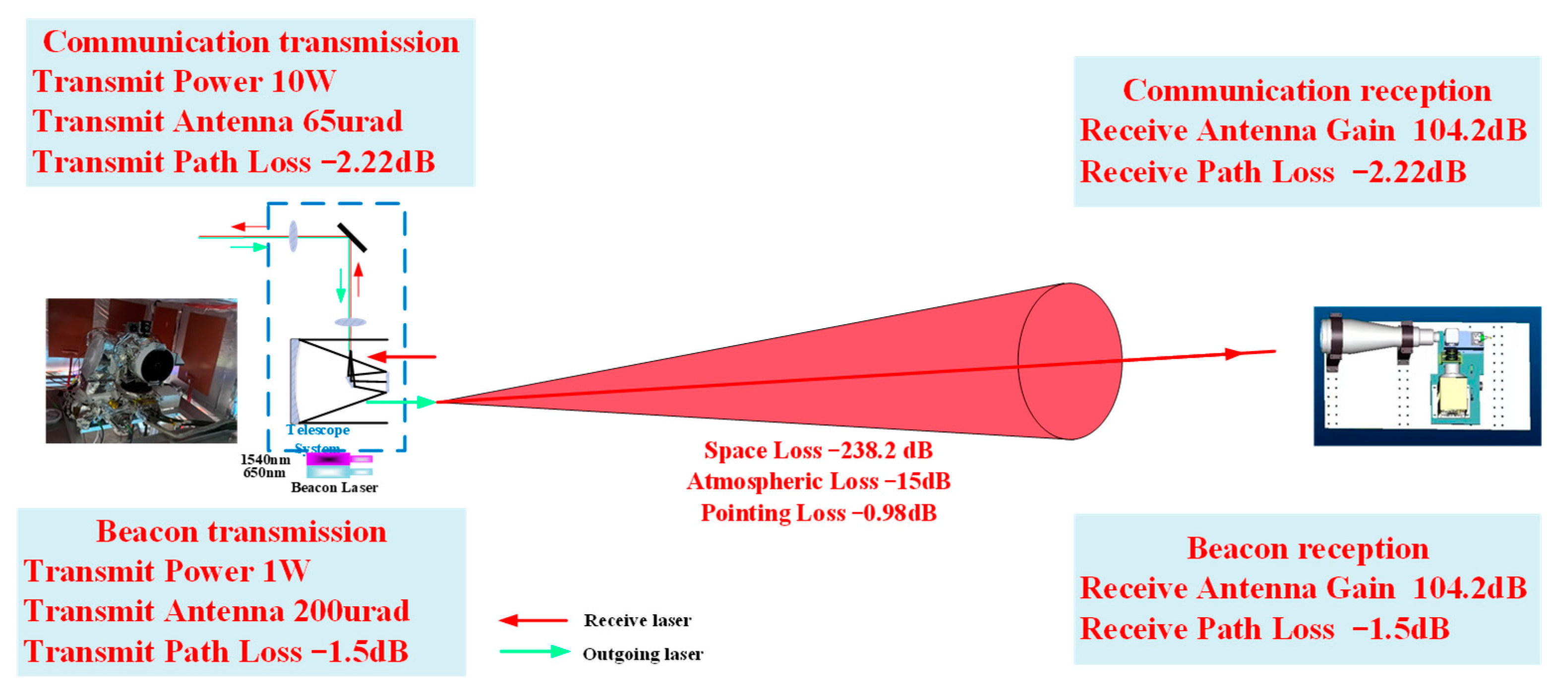
Table 2 presents the communication link budget for the 100 km/100 Gbps experiment. The schematic diagram of the key parameters of the beacon light and communication light of the laser communication link is shown in
Figure 2.
3. Ultra-Long-Range Scanning and Acquisition Technology
The success of establishing a ground-based fixed-point ultra-long-range atmospheric optical communication link primarily depends on the high-precision initial pointing accuracy between the two terminals. To achieve a ground-based laser link exceeding 100 km, we have developed a high-precision initial pointing technique for laser terminals. This technique involves integrating dual global positioning system (GPS) receivers into the terminal’s body coordinate system to measure the pointing orientation of the optical communication PAT terminal. Subsequently, the optical axis of the telescope’s exit pupil, including both the azimuth and elevation axes, is calibrated using an arbitrary star. In previous ground-based calibration procedures, the nearly fixed star Polaris was typically employed to calibrate the PAT terminal’s optical axis.
3.1. Initial Pointing
The initial pointing is a crucial factor in determining the scanning strategy of the scanning terminal. The residual error after the initial pointing defines the uncertain range of the system’s scanning area, which needs to be fully covered by the beacon light. This ensures the scanning capture probability [
17,
18]. To increase the scanning capture probability, the initial pointing accuracy must be maximized. To achieve high-precision initial alignment, the geodetic coordinates of the two terminals obtained from Global Navigation Satellite System (GNSS) must be converted into the azimuth, and elevation angles are required to point at each other. After obtaining the azimuth and elevation angles, the PAT terminal must rotate precisely according to these angles. Otherwise, significant initial pointing errors will be introduced due to the misalignment between the optical axis and the PAT terminal control system [
19].
First, the geodetic coordinates of the terminals are converted into Cartesian coordinates, as shown in Equation (1):
where
,
,
and
B,
L,
H denote latitude, longitude, and altitude.
The vector pointing to the target in the World Geodetic System 1984 (WGS84) coordinate system is denoted as
Based on the attitude information of the laser terminal’s installation on the ground, the observed vector of the target relative to the PAT terminal is transformed into the PAT terminal’s initial coordinate system (East north up (ENU)), resulting in
where
At this point, represents the direction of the PAT terminal’s initial coordinate system (ENU).
If the initial azimuth of the PAT terminal is 0° and the elevation is 0°, with the PAT terminal initially pointing true north, it is conventionally agreed that a clockwise rotation of the PAT terminal azimuth is considered positive. To make the PAT terminal point the target, the azimuth and elevation angles the PAT terminal needs to rotate are given by Equations (4) and (5).
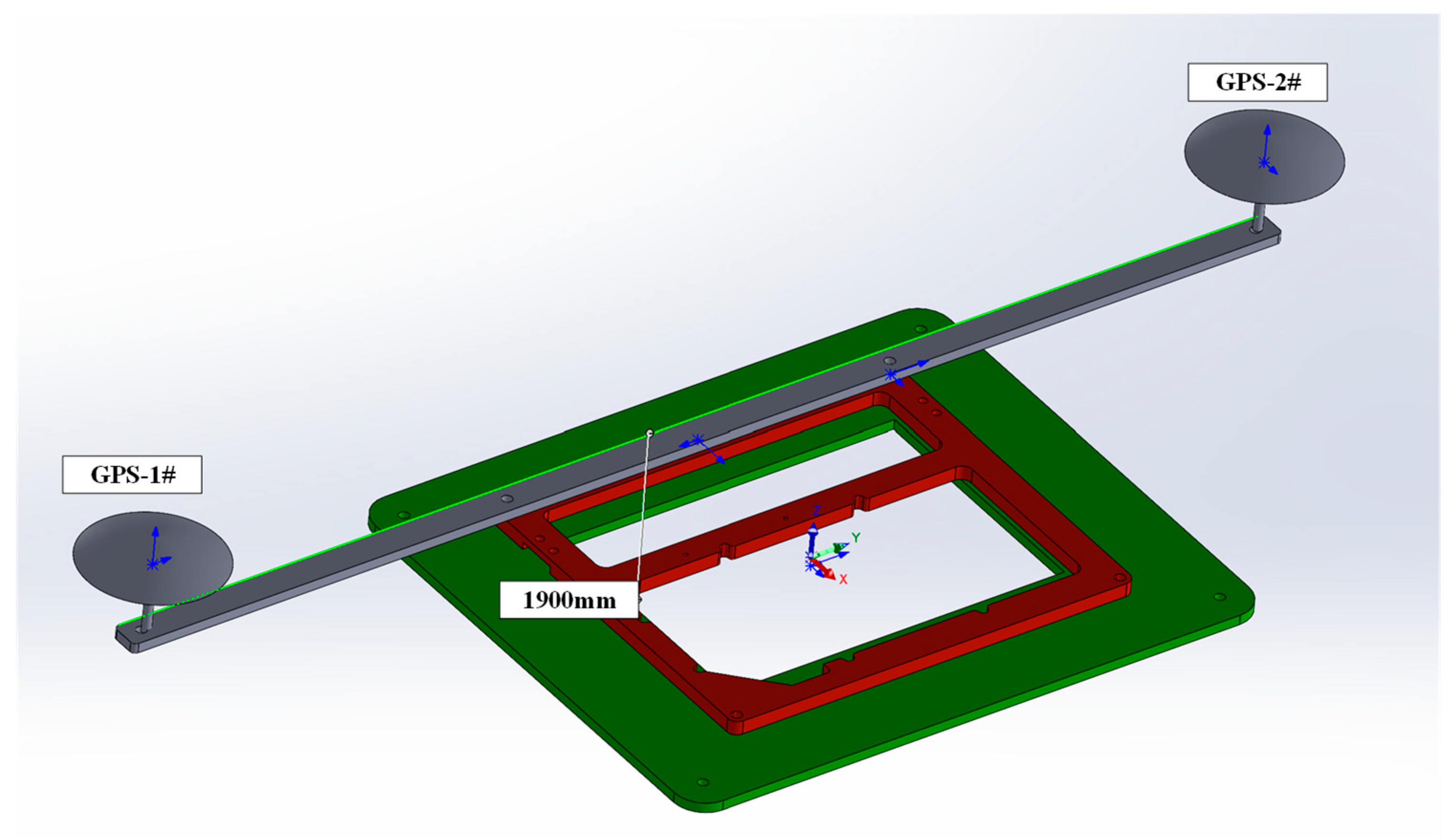
In practice, it is not possible to directly measure the absolute azimuth and elevation angles of the PAT terminal in the Cartesian coordinate system. Therefore, in this study, we designed an adapter structure for the PAT terminal, on which dual GPS receivers are installed. Through manufacturing tolerances, we ensure that the line connecting the two GPS receivers is perfectly parallel to the elevation axis of the PAT terminal. Using this method, the absolute azimuth angle can be measured, which allows the optical axis of the telescope to be calibrated by selecting any star for star calibration.
The schematic of the dual-station GPS installation is shown in
Figure 3. The dual GPS measurement devices are mounted on an extension rod parallel to the elevation axis of the optical communication PAT terminal adapter plate. The extension rod and adapter plate are manufactured to ensure their parallelism, with the length of the extension rod being 1900 mm. Through differential calculation, the angle between the line connecting the two GPS receivers and true north can be determined. When the distance between the two receivers is greater than 1 m, the measurement error is less than 0.2°.
3.2. Star Calibration for Optical Axis
By obtaining the geodetic coordinates (latitude, longitude, altitude) of the two terminals from GPS, coordinate transformation can be used to calculate the azimuth and elevation angles required for the terminal to point at the target. To minimize errors, star observations are employed, using the star’s elevation and azimuth angles as references to correct the azimuth and elevation angles of the PAT terminal. This ensures consistent calculations across the terminals and reduces errors between them. Dual GPS antennas are used to measure the angle between the PAT terminal’s initial position and true north, providing the initial azimuth for star observation [
20,
21].
The theoretical azimuth angle calculation formula is as follows:
where
is the azimuth angle obtained from GNSS,
is determined by the relationship between the baseline and the PAT terminal’s zero position,
is the azimuth angle provided by Satellite Tool Kit (STK11.0) software, and
is the azimuth angle correction value.
The theoretical elevation angle calculation formula is as follows:
where
is the elevation angle provided by STK, and
is the azimuth angle correction value.
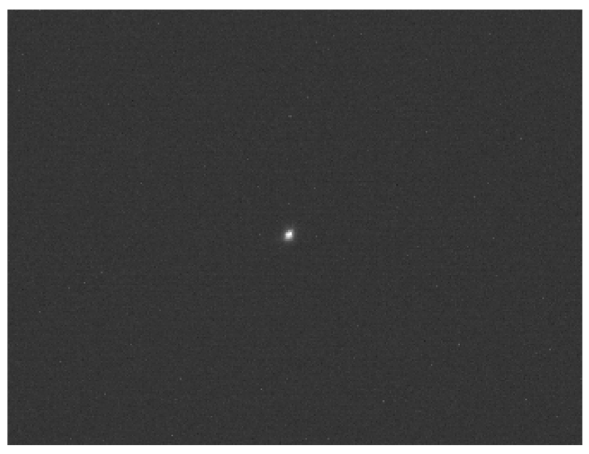
Since we can obtain the azimuth and elevation angles of the selected star relative to the PAT terminal’s body coordinate system from the ephemeris, we can use these angles to correct the azimuth and elevation angles when the PAT terminal observes the star. Before calibration begins, the PAT terminal must be installed completely horizontally on the ground, and the absolute azimuth of the PAT terminal is measured using dual-station GPS. Using the STK software, we obtain the azimuth and elevation angles of the star to be observed at a specific time and calculate the azimuth and elevation angles the PAT terminal must control to point at the star. These values are then input to the PAT terminal. After the PAT terminal rotates according to the input azimuth and elevation angles, the presence of the target star in the CCD field of view is checked. When the star image appears in the CCD field of view, as shown in
Figure 4, if the star is not visible, the PAT terminal’s elevation angle is quickly adjusted in a small range until the target star appears in the field of view. Once the star appears in the field of view, the PAT terminal is fine-tuned so that the star’s trajectory passes through the center of the field of view. After the star passes through the center of the field of view, the PAT terminal telemetry data are checked, and the time at which the star passes the center of the field of view, along with the PAT terminal’s azimuth and elevation angles, are recorded as the “actual elevation angle” and “actual azimuth angle”. The corresponding theoretical elevation angle and azimuth angle are then calculated from the STK software for the star at that moment, which are referred to as the “theoretical elevation angle” and “theoretical azimuth angle”. By comparing the theoretical and actual elevation and azimuth angles, the difference is obtained, providing the correction value for the PAT terminal’s optical axis. To minimize the error, this calibration process can be iterated multiple times. Once the ideal correction value is obtained, the azimuth and elevation angles required for the two optical communication terminals to point at each other can be easily calculated.
Table 3 shows the telescope line of sight correction results for observing different stars.
3.3. Scanning and Acquisition
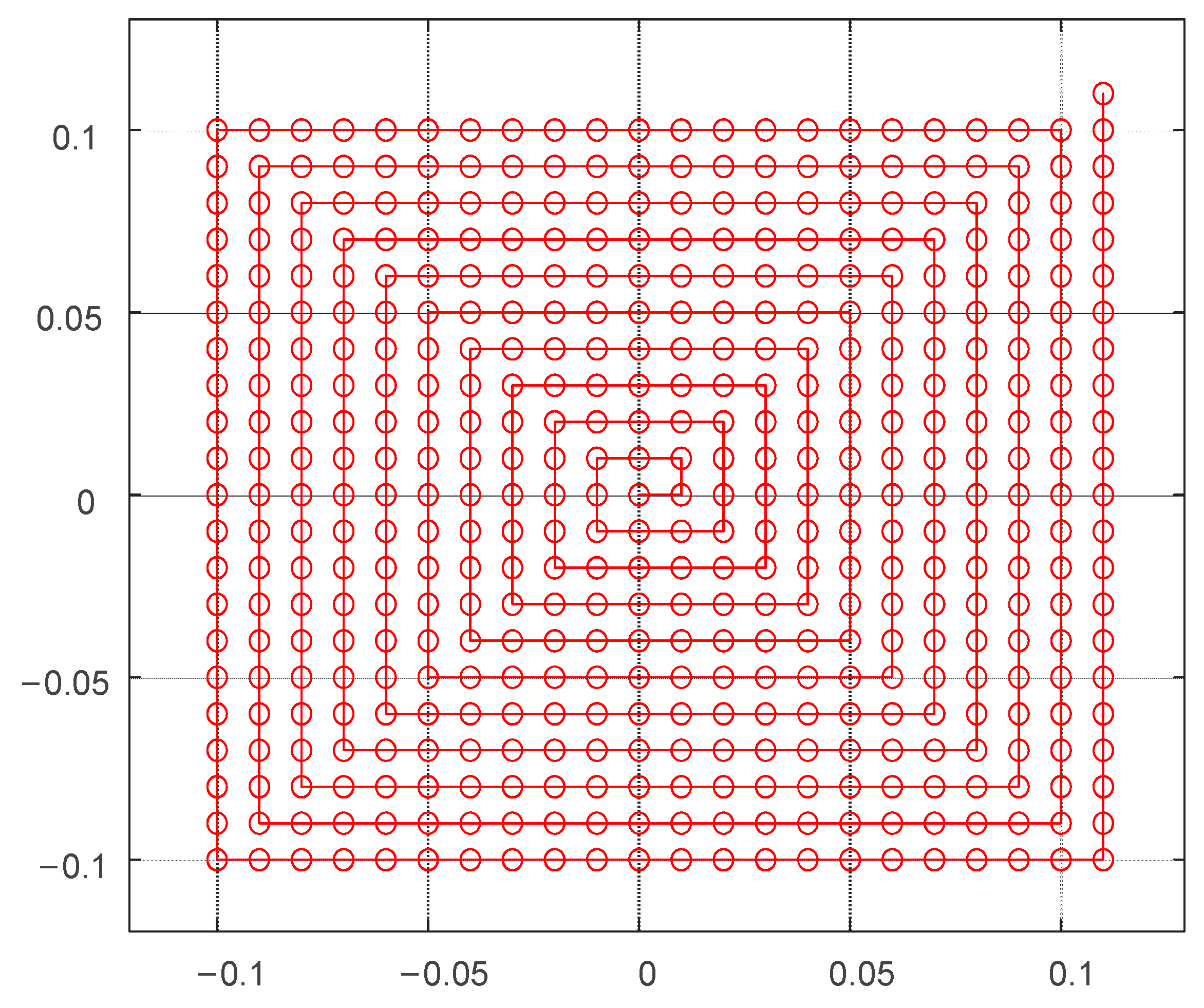
After achieving high-precision initial pointing, considering factors such as GPS measurement errors and PAT terminal execution errors, it is necessary to scan and cover the uncertain range. In this study, a rectangular spiral scanning strategy is employed. Taking into account platform attitude errors, positioning errors, PAT terminal execution errors, and some redundancy, scanning is conducted within an uncertain range of 0.2°. The scanning trajectory is shown in
Figure 5.
The 400 μrad coarse beacon is used to scan the uncertain area. The scanning terminal’s beacon light has a transmission power of 1 W, with a scanning range of ±0.1°, a scanning step size of 0.01°, and a dwell time of 0.1 s. The total scanning time is 46.3 s. The dual-terminal collection uses a staring scan approach. When the staring terminal receives the beacon light, it quickly tracks the signal and sends a signal light to the scanning terminal. The scanning terminal stops scanning once it receives the signal light from the staring terminal, completing the laser link acquisition between the two terminals. In this system, the scanning system is mainly used in the coarse alignment stage. It drives the fast reflector (FSM) through a preset program to search a wide range of angles and compensate for initial installation errors and environmental disturbances. In this stage, the system operates in an open loop, with a slow response speed and low link stability. The fine tracking system mainly controls the fast reflector based on the CCD camera’s spot position error feedback to achieve high-precision closed-loop control. In this stage, the dynamic jitter caused by some turbulence can be suppressed to maintain link stability.
4. Experimental Results
We conducted an in-depth study using the system developed in this research and performed the first-ever ground-based ultra-long-distance atmospheric optical communication experiment over 100 km/100 Gbps in the Qinghai Lake region, China. Prior to this, we also conducted numerous near-field outdoor experiments to verify the effectiveness of our system. Although the Qinghai Lake area is at a high altitude, with atmospheric particle concentrations much lower than at lower altitudes, it is important to note that ultra-long-distance atmospheric optical communication experiments still face severe atmospheric turbulence, which significantly impacts the laser energy coupling efficiency. Our system does not include any turbulence compensation systems, such as adaptive optics. However, to validate our laser scanning capture, we can perform this verification at any time of the day. To demonstrate the 100 Gbps high-speed optical communication, we chose the time window with the lowest atmospheric turbulence intensity during the day for the communication experiment.
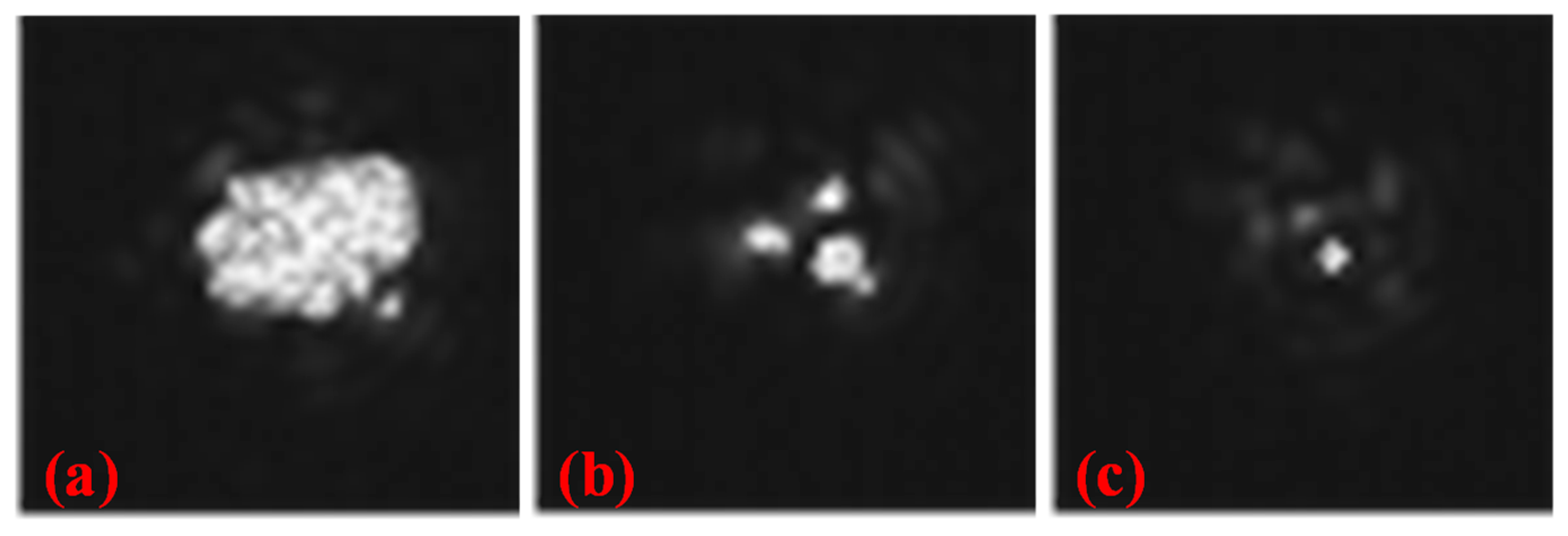
When the signal light spot emitted by the staring terminal is detected on the scanning terminal’s CCD camera, an image is recorded, and the position of the spot is tracked in real-time. The position of the spot on the detector is adjusted by manually adjusting the PAT terminal and fine-tracking fast mirrors, so that the spot is positioned at the location with the highest fiber coupling efficiency.
Figure 6 shows the images of the light spot received under weak, moderate, and strong turbulence conditions. Under weak turbulence, the laser power coupling efficiency is approximately 10%, whereas under strong turbulence, the laser power coupling efficiency is less than 1%.
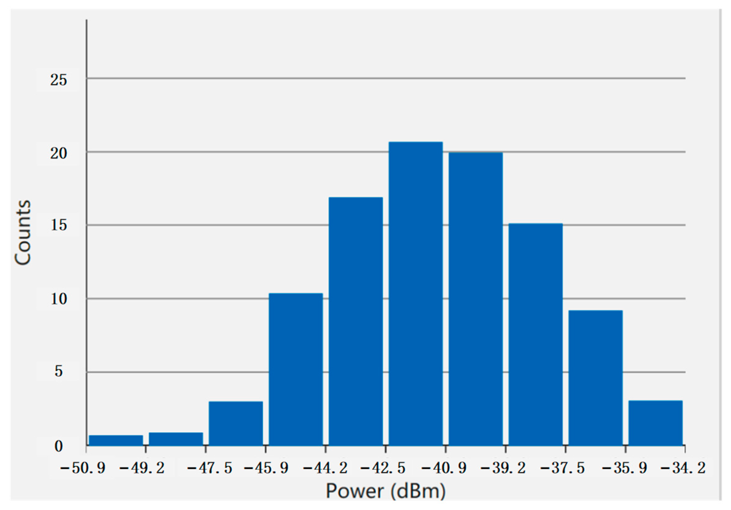
We used a high-speed optical power meter with a sampling frequency of 1 kHz to statistically measure the received laser energy under weak turbulence, and the results are shown in
Figure 7. From the figure, it is clear that, under favorable atmospheric link conditions, the maximum optical power coupled to the scanning terminal through the optical system is −34.24 dBm, the minimum optical power is −50.23 dBm, and the average optical power, calculated from the statistics, is −40.31 dBm, which achieved the expected ideal result. Under these power coupling conditions, 112 Gbps atmospheric optical communication was achieved in the Qinghai Lake area, with the optimal bit error rate (BER) of 3E-3.
Although the current experiment utilized a 10 W transmitter in a controlled, remote environment, practical deployment mandates adherence to international laser safety standards. The beam’s narrow divergence (65 μrad) ensures rapid power density attenuation: at 1 km, the spot diameter expands to ~6.5 cm, reducing power density to <1.5 mW/cm2 (far below the IEC 60825-1 Class 1 limit of 10 mW/cm2 for 1550 nm lasers). This inherently safe design eliminates public exposure risks under normal operation. For additional safeguards, we propose integrating real-time LiDAR-based intrusion detection (triggering beam shutdown within 50 ms) and deploying transceivers in restricted-access zones (e.g., rooftop towers) with public hazard signage. Compliance with IEC 60825-1 certification will further ensure operational safety across all scenarios.
5. Discussion and Conclusions
Although there have been numerous reports on free-space optical communication, demonstration systems for ground-based local area information transmission networks are still worth exploring. Unlike space-based optical communication, ground atmospheric environments require faster network setup capabilities and the ability to cope with more complex atmospheric conditions. Therefore, to effectively address the rapid acquisition of ultra-long-distance atmospheric laser links, we designed a high-precision initial pointing technique for the laser terminal. By observing any star and correcting the optical axis pointing errors of the optical communication terminal, the initial pointing can be completed rapidly, and scanning acquisition can be performed in a short amount of time. This technique enables the fast deployment of ground-based local optical communication networks and demonstrates ultra-100 Gbps high-speed optical communication in weak turbulence windows.
In conclusion, our research experimentally demonstrated the rapid acquisition and ultra-high-speed optical communication of ground-based ultra-long-distance atmospheric optical communication links. The high-precision laser terminal initial pointing method we proposed effectively reduces the scanning uncertainty region, and the coarse beacon scan enables rapid scanning acquisition. Multiple experimental results show that dual-end link scanning acquisition can be achieved within an uncertainty range of ±0.1°, which represents a breakthrough for ground-based atmospheric optical communication systems. In the future, this research will continue, and we will further investigate high-precision light spot position extraction techniques under turbulence effects, to enable long-term stable tracking of moving platform atmospheric optical communication links.
Author Contributions
Conceptualization, X.W. and J.H.; methodology, X.W.; software, C.W.; validation, X.W. and X.M.; formal analysis, X.W.; investigation, X.M.; resources, J.H.; data curation, X.W.; writing—original draft preparation, X.W.; writing—review and editing, J.H.; visualization, C.W.; supervision, J.H.; project administration, C.W.; funding acquisition, X.W. All authors have read and agreed to the published version of the manuscript.
Funding
This research was funded by Supported by the National Natural Science Foundation of China, grant number 60171009.
Institutional Review Board Statement
Not applicable.
Informed Consent Statement
Not applicable.
Data Availability Statement
The data presented in this study are available upon reasonable request from the corresponding author. The data are not publicly accessible due to confidentiality agreements with collaborating institutions and the inclusion of proprietary technical specifications related to the experimental optical communication system.
Acknowledgments
The authors express sincere thanks for the experiments provided by the Photoelectric Tracking and Measurement Technology Laboratory, Xi’an Institute of Optics and Precision Mechanics, CAS.
Conflicts of Interest
The authors declare no conflicts of interest.
References
- Jahid, A.; Alsharif, M.H.; Hall, T.J. A contemporary survey on free space optical communication: Potentials, technical challenges, recent advances and research direction. J. Netw. Comput. Appl. 2022, 200, 103311. [Google Scholar] [CrossRef]
- Alvarez, J.; Walls, B. Constellations, clusters, and communication technology: Expanding small satellite access to space. In Proceedings of the 2016 IEEE Aerospace Conference, Big Sky, MT, USA, 5–12 March 2016; IEEE: Piscataway, NJ, USA, 2016. [Google Scholar]
- Zhi, H.; Jiang, X.; Wang, J. Multicolour photometry of LEO mega-constellations Starlink and OneWeb. Mon. Not. R. Astron. Soc. 2024, 530, 5006–5015. [Google Scholar] [CrossRef]
- Belgaonkar, V.V.; Triveni, C.L.; Sundaraguru, R. Free space optical communication using OQPSK in the presence of strong atmospheric turbulence and losses. Opt. Quantum Electron. 2024, 56, 1669. [Google Scholar] [CrossRef]
- Chow, C.W. Recent advances and future perspectives in optical wireless communication, free space optical communication and sensing for 6G. J. Light. Technol. 2024, 42, 3972–3980. [Google Scholar] [CrossRef]
- Gazzi, E.K.A.; Ali, E.H.; Mohammed, A.J. Development and Execution of an FSO Communication System to Track the Scattered Laser Beam During Atmospheric Turbulence. J. Opt. 2024, 1–8. [Google Scholar] [CrossRef]
- Wang, L.; Liang, Y.; Qi, Z.; Liu, P.; Shi, Z.; Zhu, H.; Wang, Y. All-light communication network for space-air-sea integrated interconnection. Opt. Express 2024, 32, 9219–9226. [Google Scholar] [CrossRef] [PubMed]
- Al-Tarawneh, L.; Alqatawneh, A.; Tahat, A.; Saraereh, O. Evolution of optical networks: From legacy networks to next-generation networks. J. Opt. Commun. 2024, 44 (Suppl. S1), s955–s970. [Google Scholar] [CrossRef]
- Patle, N.; Raj, A.B.; Joseph, C.; Sharma, N. Review of fibreless optical communication technology: History, evolution, and emerging trends. J. Opt. Commun. 2024, 45, 679–702. [Google Scholar] [CrossRef]
- Toyoshima, M.; Jono, T.; Nakagawa, K.; Yamamoto, A. Optimum divergence angle of a Gaussian beam wave in the presence of random jitter in free-space optical communication systems. J. Opt. Soc. Am. A 2002, 19, 567–571. [Google Scholar] [CrossRef] [PubMed]
- Zhang, G.; Wu, J.; Li, Y.; Wang, X.; Yu, X.; Gao, S.; Ma, L. A Review of Variable-Beam Divergence Angle FSO Communication Systems. Photonics 2023, 10, 756. [Google Scholar] [CrossRef]
- Alatwi, A.M.; Rashed, A.N.Z.; Parvez, A.S.; Paul, B.K.; Ahmed, K. Beam divergence and operating wavelength bands effects on free space optics communication channels in local access networks. J. Opt. Commun. 2024, 44 (Suppl. S1), s823–s831. [Google Scholar] [CrossRef]
- Toyoshima, M.; Takahashi, N.; Jono, T.; Yamawaki, T.; Nakagawa, K.; Yamamoto, A. Mutual alignment errors due to the variation of wave-front aberrations in a free-space optical communication link. Opt. Express 2001, 9, 592–602. [Google Scholar] [CrossRef] [PubMed]
- Yang, Y.; Tan, L.; Ma, J. Mutual alignment errors due to localized distortion in free-space optical communication links. Opt. Commun. 2008, 281, 4180–4187. [Google Scholar] [CrossRef]
- Fahs, B.; Romanowicz, M.; Kim, J.; Hella, M.M. A self-alignment system for LOS optical wireless communication links. IEEE Photonics Technol. Lett. 2017, 29, 2207–2210. [Google Scholar] [CrossRef]
- Li, M.; Li, J.; Li, B.; Chen, J.; Jiang, Y. Effect of Lateral Alignment Error on Communication Performance of Space Chaotic Optical Communication System. IEEE J. Quantum Electron. 2023, 59, 8000409. [Google Scholar] [CrossRef]
- Kaymak, Y.; Rojas-Cessa, R.; Feng, J.; Ansari, N.; Zhou, M.C.; Zhang, T. A survey on acquisition, tracking, and pointing mechanisms for mobile free-space optical communications. IEEE Commun. Surv. Tutor. 2018, 20, 1104–1123. [Google Scholar] [CrossRef]
- Wu, R.; Zhao, X.; Liu, Y.; Song, Y. Initial pointing technology of line of sight and its experimental testing in dynamic optical communication system. IEEE Photonics J. 2019, 11, 7903008. [Google Scholar] [CrossRef]
- Wang, P.; Liu, X.; Cao, T.; Fu, H.; Wang, R.; Guo, L. Impact of nonzero boresight pointing errors on the performance of a relay-assisted free-space optical communication system over exponentiated Weibull fading channels. Appl. Opt. 2016, 55, 7593–7603. [Google Scholar] [CrossRef] [PubMed]
- Wang, Z.; Peng, C.; Zhang, T.; Wang, Q.; Liu, S.; Liu, X.; Wang, Y.; Huang, Y.; He, D. Stellar correction pointing model based on line-of-sight attitude measurements for optical communication telescopes on motion platforms. Appl. Opt. 2024, 63, 9118–9127. [Google Scholar] [CrossRef]
- Khmelev, A.V.; Duplinsky, A.V.; Kurochkin, V.L.; Kurochkin, Y.V. Stellar calibration of the single-photon receiver for satellite-to-ground quantum key distribution. J. Phys. Conf. Series. 2021, 2086, 012137. [Google Scholar] [CrossRef]
| Disclaimer/Publisher’s Note: The statements, opinions and data contained in all publications are solely those of the individual author(s) and contributor(s) and not of MDPI and/or the editor(s). MDPI and/or the editor(s) disclaim responsibility for any injury to people or property resulting from any ideas, methods, instructions or products referred to in the content. |
© 2025 by the authors. Licensee MDPI, Basel, Switzerland. This article is an open access article distributed under the terms and conditions of the Creative Commons Attribution (CC BY) license (https://creativecommons.org/licenses/by/4.0/).


