Article

The Teleoperation of Robot Arms by Interacting with an Object’s Digital Twin in a Mixed Reality Environment

1
School of Computer Science and Technology, Changchun University of Science and Technology, Changchun 130022, China
2
Jilin Provincial International Joint Research Center of Brain Informatics and Intelligence Science, Changchun 130022, China
3
Zhongshan Institute of Changchun University of Science and Technology, Zhongshan 528437, China
*
Author to whom correspondence should be addressed.
Appl. Sci. 2025, 15(7), 3549; https://doi.org/10.3390/app15073549
Submission received: 10 January 2025 / Revised: 20 February 2025 / Accepted: 27 February 2025 / Published: 24 March 2025
(This article belongs to the Section Computing and Artificial Intelligence)

Abstract

:
The teleoperation of robot arms can prevent users from working in hazardous environments, but current teleoperation uses a 2D display and controls the end effector of robot arms, which introduces the problem of a limited view and complex operations. In this study, a teleoperation method for robot arms is proposed, which can control the robot arm by interacting with the digital twins of objects. Based on the objects in the workspace, this method generates a virtual scene containing digital twins. Users can observe the virtual scene from any direction and move the digital twins of the objects at will to control the robot arm. This study compared the proposed method and the traditional method, which uses a 2D display and a game controller, through a pick-and-place task. The proposed method achieved 45% lower scores in NASA-TLX and 31% higher scores in SUS than traditional teleoperation methods. The results indicate that the proposed method can reduce the workload and improve the usability of teleoperation.

1. Introduction

Robots are used in various hazardous or challenging tasks, such as disaster search and rescue [1], industrial automation [2,3], space exploration [4], surgical applications [5], military applications [6], and underwater exploration [7]. In industrial automation, most production lines achieve automation with the help of robots, such as product picking and placing, welding, and painting. However, when facing an open work environment, dynamic and changing workflows, and hard-to-define human–robot cooperation requirements [8,9], it is difficult to implement robotic automation. In such environments, the teleoperation of robots can integrate the advantages of robots and users to complete complex tasks. Users leverage their perception, judgment, and adaptability to make the remote control of robots more effective, and the robots keep users away from danger. But traditional robot teleoperation provides only a limited field of view of the workspace, which makes it difficult for users to develop effective spatial understanding, and traditional teleoperation also depends on physical devices to control robots, which may lead to incorrect operation [10].
The traditional remote interfaces mainly include joysticks [11,12], haptic controllers [13], a keyboard, and a mouse [14], which have been extensively researched in robot arm teleoperation. The interface of the Fanuc industrial robot is based on a small touchscreen with a complex panel filled with buttons and allows users to operate the robot remotely. In this case, only experienced users can manage the complex interface. Some manufacturers have developed more user-friendly interfaces. KUKA and ABB provide interfaces that can carry out most of the interaction by touching the screen panels. However, users need to program the industrial robot’s motion to control the industrial robot by their interfaces. Before programming robots, users need to learn previous knowledge in areas such as robotics, automation, and computer science. To address the issue of the complex interface, J. Ernesto Solanes et al. [15] used the Augmented Reality (AR) interface and game controller to control the industrial robot. In the interface, several holograms of task messages are visualized, such as the position and orientation of the end effector, the direction of the command movements, the camera view, the robot velocity, the target position on the object, and the end effector trajectory. The holograms are registered in the surrounding environment of the robot through the AR headset. Users use a game controller to control the robot remotely and interact with the holograms. The results show that this method is more intuitive and easier to use and significantly improves the speed of remote operations.
Mixed reality (MR) offers more user-friendly remote interfaces and is increasingly important in many industries. Mario Caterino et al. [16] conducted an empirical study to measure the errors performed by two groups of people performing a working task through a virtual reality (VR) device to investigate the impact of robots on human operators. One group worked with a robot, and the other worked without the presence of a robot. Although statistical results showed that there were no significant differences between the two groups, qualitative analysis proved that the presence of the robot led to people paying more attention during the execution of the task but also resulted in a worse learning experience. Lorraine I. Domgue K. et al. [17] compared Augmented Reality (AR), virtual reality (VR), and video-based tasks in safety training. The results showed that AR outperformed traditional video training in terms of knowledge retention, long-term self-efficacy, and quality of instruction. The AR experience was not as effective as the VR experience in all these areas, but the AR group experienced a smaller decrease in knowledge over time. Sepehr Madani et al. [18] proposed a fiducial-based hand–eye calibration method. They utilized the precision of surgical navigation systems (NAV) to address the hand–eye calibration problem, thereby localizing the mixed reality (MR) camera within a navigated surgical scene. The accuracy of this method complies with the accuracy and stability requirements essential for surgical applications. Tienong Zhang et al. [19] proposed a real-time two-branch approach that integrated human action-based human factor evaluations and object-based assembly progress observations. The experiments were carried out on human–object-integrated performances in the smart AR assembly, and the results illustrate that the proposed method alleviated the cognitive load.
For the teleoperation of robots, recent studies have used MR for gesture recognition to control the digital twin of the real robot arm. The digital twin is a virtual model which is designed to accurately reflect the real object. Zhang et al. [20] designed an arm-free human–robot interaction interface (HRI) based on MR feedback. The HRI allows people to control a robot using speech recognition. This method can complete the grasping task, but the efficiency of this method is not high. Samir Yitzhak Gadre et al. [21] proposed an MR-based interaction interface that allowed users to create and edit the robot’s motion through waypoints. These waypoints represent the position where the robot arm’s end effector must move, and a series of waypoints perform a motion. The interaction interface displays the predicted path of the robot arm from one waypoint to the next. Similarly, Rivera-Pinto et al. [22] used an MR device to control the digital twin of the robot arm’s end effector to indicate the robot arm’s trajectory through gestures. This method also allowed users to simultaneously modify the virtual end effector’s six Degrees of Freedom by holding and moving the virtual end effector. For mobile robots, Cruz Ulloa et al. [23] used gestures to move the virtual end effector to control the robot arm on the quadruped robot through the MR device.
In addition, remote interfaces can influence the efficiency of teleoperation, and the method of observing workspace can also influence the efficiency of teleoperation. In traditional robot arm teleoperation systems, users can only obtain the necessary information from the 2D display to control the robot arm, but it is difficult for users to obtain information using a 2D display. The main reason for this is that the information on the working scene provided by the 2D display is neither intuitive nor natural for the user. Cody Glover et al. [24] used a single 2D display to show the working scene of the remote robot arm. When users observed the workspace from one direction, they could not perceive the depth directly and had difficulty in accurately judging the distance between the robot arm’s end effector and the objects. Because of the difficulty of observing objects, the method of using a single 2D display causes many collisions that occur between the robot arm and the objects. Additionally, users cannot observe the workspace and the controller simultaneously during the operation, which prevents users from paying attention to the robot arm’s operation activities. Vicent et al. [25] used three monocular cameras to address the difficulty in judging the distance between the end effector and the objects. This method allowed users to observe the workspace and to judge the distances of objects from different perspectives. However, because the teleoperation robot system becomes more complex, the method using multiple 2D feedback to avoid collisions between the robot and the surrounding objects leads to inefficient robot operations and increases the operator’s workload.
MR makes it convenient for users to understand the work environment and provides users with better experiences. Improving 2D visualization to 3D visualization can offer additional depth information to users [26,27,28]. Eric Rosen et al. [29] proposed a mixed reality head-mounted display (HMD) that overlaid the anticipated movement of a robot arm to the real environment. In their experiment, they compared the performance of HMD with a 2D interface and no visualization interface. Users could only observe the real robot arm with no visualization interface. The 2D interface displayed a 3D model of the robot arm, the predicted sparse motion trajectory of the robot arm, and a 3D point cloud of the working scene. The HMD overlaid the predicted motion trajectory on the real robot arm. The results showed that the HMD significantly outperformed the 2D interface, with the collision prediction accuracy improving by 15% and the time reduced by 38%. There was no significant difference between the lack of a visualization interface and the 2D interface in collision prediction. Su et al. [30] compared the impact of three different visual schemes on the robot arm teleoperation, including mixed reality with multi-perspective 2D monocular RGB camera views (MR-2D), which used two 2D monocular cameras to provide the workspace’s information, mixed reality with 3D stereoscopic vision (SV) and monocular RGB (baseline)-integrated vision (MR-3DSV), which adds a stereoscopic camera in the MR-2D to provide an extra stereoscopic vision, and mixed reality with 3D point cloud (PC) and monocular RGB (baseline)-integrated vision (MR-3DPC) which adds a Kinect V2 depth camera in the MR-2D to provide an extra 3D point cloud. The experiment concluded that MR-2D was the worst among the three visual schemes, and MR-3DSV was inferior to MR-3DPC in terms of task execution time, user workload, and system usability. Similarly, De Pace et al. [31] used a virtual reality (VR) controller to remotely operate a robot arm and compared three different interfaces: a pure virtual robot arm interface, a point cloud-only interface, and a point cloud combined with a virtual robot arm interface. The results indicate that the pure point cloud interface was less efficient than the rendered virtual robot arm interface. Recently, three-dimensional virtual scenes have been mainly presented in the form of point cloud models. The data volume of point cloud models is often enormous, which makes real-time scene modeling, data conversion, and rendering very challenging. To address the limitations of the point cloud interfaces, Zhou et al. [32] used prefabricated 3D models to replace the point clouds of fixed objects to reduce the data volume, but this method still uses the point clouds to display the unfixed objects.
Currently, teleoperation methods based on mixed reality are implemented by controlling the position of the robot arm’s end effector or the angles of its joints [15,33,34,35], such as the method proposed by Rivera-Pinto [22], which allows users to interact with the robot arm’s digital twin to control its movement, but users can only manipulate the virtual end effector. However, these methods have requirements for the user’s proficiency, and the unskilled operation is prone to collision between the robot arm and the surrounding objects.
In order to reduce the difficulty of the teleoperation system, this paper presents a method to teleoperate the robot arm in a mixed reality environment by directly interacting with the digital twin of the target object. This method allows the user to move the digital twin of a real object in a virtual scene to indicate the object to be moved and the target position to be placed without directly controlling the robot arm. To achieve this goal, the objects in the working scene are identified and located, and their 3D models are created in advance. An operable virtual scene is then quickly generated in HoloLens2 through server communication. The target application picks and places objects in dangerous situations. Our teleoperation method approach enables seamless integration of the teleoperation of the robot arm with an immersive human–machine interface. This method provides a virtual scene that can be viewed from any angle and an easy-to-learn operation method. Our experiments show that this method reduces workload by 45% and improves usability by 31% compared to teleoperation methods using a 2D display and game controller.

2. Materials and Methods

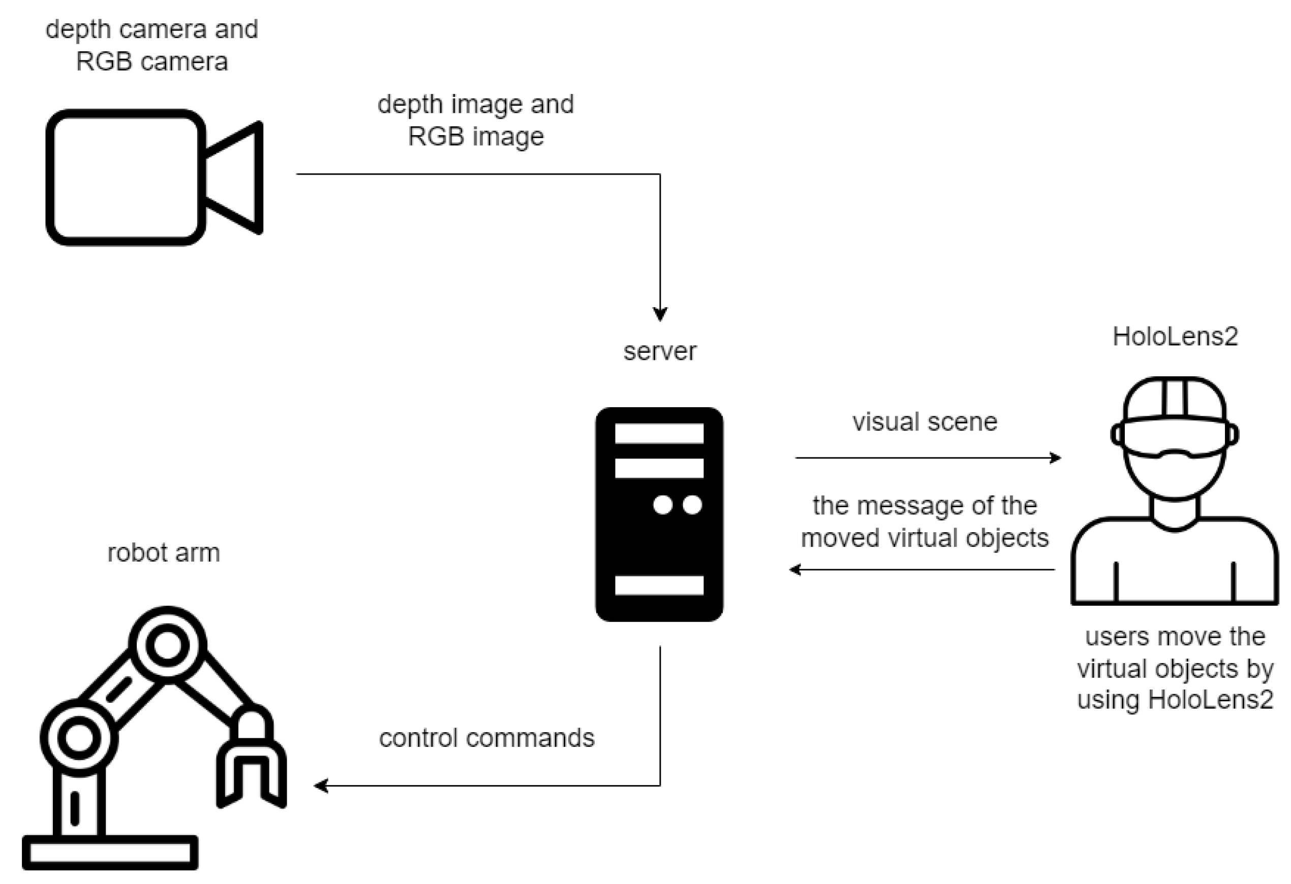
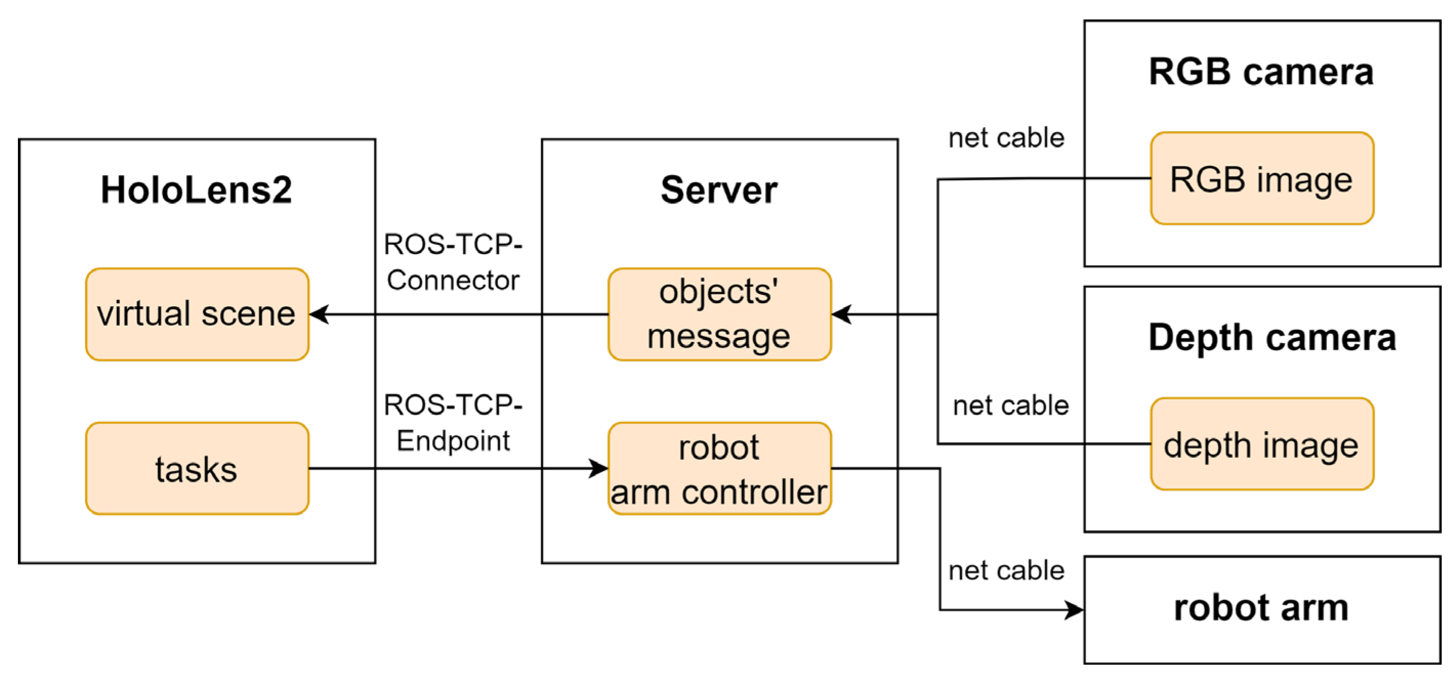
2.1. System Architecture

This study uses a HoloLens2 mixed-reality device, a server, a Kinova Gen3 robot arm, a depth camera, and an RGB camera. As shown in Figure 1, the HoloLens2 is used to provide virtual scenes to users after receiving object information from the server. The server is implemented on a notebook computer. The server is used to connect the other devices and send the messages that the other devices need. The Kinova Gen3 robot arm is a 6DoF robot arm and is used as the execution module to pick up objects. The robot arm receives the target object and target position from the server. The depth camera is the Intel RealSense D415, and the RGB camera is the built-in RGB camera of the RealSense D415. Both cameras are used to acquire images of the work scene.
Figure 2 is a flowchart of the method proposed in this paper. The first step of the method is connecting the robot arm to the server and connecting the server to the HoloLens2. Subsequently, the RGB and depth cameras capture RGB and depth images of the objects in the robot arm’s workspace. Then, object recognition and localization are performed. In this study, cubes of different colors were used as objects because they were easy to recognize and grasp. Color recognition was employed for object identification. This process uses the RGB image and the depth image to obtain the category of objects and the coordinates of the objects in the coordinate system of the robot arm’s base. After object recognition and localization, the category and the position of the objects are sent to HoloLens2 via communication between the Robot Operating System (ROS) and HoloLens2, and a virtual scene is generated. In the virtual scene, users move the digital twins of objects using gesture commands, and HoloLens2 sends the task information to the server. When the server receives the user’s task, the server autonomously controls the robot arm to complete the tasks.

2.2. The Communication Between Server and MR Device

In our approach, Unity is used to design the interaction interface and generate a virtual scene in the HoloLens2, and ROS is used to control the robot arm on the server. Therefore, data exchange is necessary between Unity and ROS. This section describes the communication setup between Unity in HoloLens2 and ROS on the server.
The system uses the ROS-TCP-Connector and ROS-TCP-Endpoint to provide a network communication solution. ROS-TCP-Connector is used in Unity to receive and send ROS messages. ROS-TCP-Endpoint is used in ROS and receives messages sent from Unity. More specifically, in Unity, a WebSocket is established. The WebSocket allows Unity to use a specific IP address to connect to the ROS, and Unity transmits and receives data via the WebSocket connection. Relevant nodes are established in Unity, which can publish topics and subscribe to topics. In practice, ROS and Unity are configured to use the same network IP address. Then, ROS, which is running on the server, can publish any information about the objects in the form of topics and can subscribe to the information on the tasks in the form of topics published by Unity. On the other hand, Unity, which is running in the HoloLens2, can subscribe to topics of information from objects published by the ROS and can publish topics about the task’s information.
As shown in Figure 3, before constructing the virtual scene, the information about objects in the scene needs to be published in the form of a topic. This information includes the objects’ category and coordinates in the robot arm base coordinate system. The information is obtained by the server through processing the RGB image and depth image. When ROS publishes object information, the application in HoloLens2 receives the information and generates the virtual objects in the virtual scene.
In HoloLens2, Unity can subscribe to the topics published by ROS to obtain object information through the ROS-TCP-Connector. After the user indicates the target object and the destination position of the target object via HoloLens2, Unity publishes a topic about the target object and destination position through ROS-TCP-Connector. Then, ROS subscribes to this topic through ROS-TCP-Endpoint and subsequently performs the grasping operation.

2.3. The Location of Objects

2.3.1. Aligning RGB Image and Depth Image

Object recognition (color recognition) requires the RGB image, but the RGB image lacks the depth information of objects, which leads to the difficulty of locating an object. Therefore, the depth image is necessary to obtain the objects’ depth information. The RGB image with a resolution of 1280 × 720, and the resolution of the depth image is 480 × 270. The difference in the resolution between the two images is significant, so it is necessary to align the two images, which means finding the corresponding pixels between the depth image and the RGB image. This study can directly calculate the corresponding pixels in the depth image through the pixels in the RGB image. While the traditional alignment method traverses the depth image in advance, calculating the corresponding pixels in the RGB image, it then obtains the corresponding pixels in the depth image through the pixels in the RGB image.
The method of this paper uses the RGB image to recognize the objects and determine the bounding box of the objects. The bounding box is presented by four values ( x , y , w , h ) , where x , y represents the coordinates of the upper left corner of the bounding box and w , h represents the width and height of the bounding box.
The coordinates of the bounding box’s center x + w / 2 , y + h / 2 are used to represent the coordinates of the object, and this value is used to obtain the depth value of the object in the depth image. Assuming that the pixel coordinate of the point P in the depth image is d j d i 1 , it is calculated as follows:
d j d i 1 = K D Z D 1 X D Y D Z D
where K D is the intrinsic matrix of the depth camera; Z D is the depth value of P in the depth camera coordinate system; and X D Y D Z D presents the coordinate of P in the depth camera coordinate system. The coordinate points from the RGB camera coordinate system to the depth camera coordinate system can be calculated as follows:
X D Y D Z D = R R D X R Y R D R + T R D
where R R D presents the rotation matrix from the RGB camera coordinate system to the depth camera coordinate system, and T R D is the transformation matrix from the RGB camera coordinate system to the depth camera coordinate system. X R Y R Z R represents the point coordinates in the RGB camera coordinate system, which can be calculated as follows:
X R Y R Z R = K R 1 r j r i 1 Z R
where K R is the intrinsic matrix of the depth camera, Z R is the depth value of point P in the RGB camera coordinate system, and r j r i 1 presents the coordinate of point P in the pixel coordinate system of the RGB camera.
The X R Y R Z R in Formula (2) is replaced by Formula (3), and the calculation is given as follows:
X D Y D Z D = R R D K R 1 r j r i 1 Z R + T R D
The X D Y D Z D in Formula (1) is replaced by Formula (4), and the calculation is given as follows:
d j d i 1 = K D Z D 1 ( R R D K R 1 r j r i 1 Z R + T R D )
In practice, using Equation (4) with the RGB image and the depth image can obtain the object’s coordinate in the depth image.
After obtaining the coordinates of the object in the depth image, it is necessary to unify the coordinate systems. This study involved three coordinate systems: the depth camera coordinate system (cam frame), robot arm base coordinate system (root frame), and object coordinate system (obj frame) [36]. Because our depth camera was fixed on the robot arm, the position between their coordinate systems was relatively fixed, and the coordinate transformation matrix of the robot joint and the depth camera was provided by the manufacturer. The whole coordinate transformation matrix of the robot arm was directly added to the TF tree in ROS. Through the TF tree, the real-time transformation between the depth camera coordinate system and robot arm base coordinate system could be achieved. The specific formula for this is as follows:
x o y o z o = R c a m r o o t d j d i d z + T c a m r o o t
where x o y o z o presents the coordinate of the object in the root frame; R c a m r o o t represents the rotation matrix from the camera’s frame to the root frame; and T c a m r o o t represents the translation matrix from the camera frame to the root frame. d j d i d z represents the coordinates of the object in the depth image, where d z presents the value of depth. The R c a m r o o t and the T c a m r o o t are provided by the manufacturer of the robot arm.

2.3.2. Coordinates of Transformation Between ROS and Unity

After obtaining the coordinates of the objects in the robot arm base coordinate system, they need to be mapped to the corresponding position in Unity. However, because the world coordinate system in ROS is different from the coordinate system in Unity, coordinate transformation is required. The transformation equation is as follows:
Positions:
x u n i t y = x r o s   y u n i t y = z r o s z u n i t y = y r o s
Rotations:
q x u n i t y = q x r o s   q y u n i t y = q z r o s q z u n i t y = q y r o s q w u n i t y = q w r o s

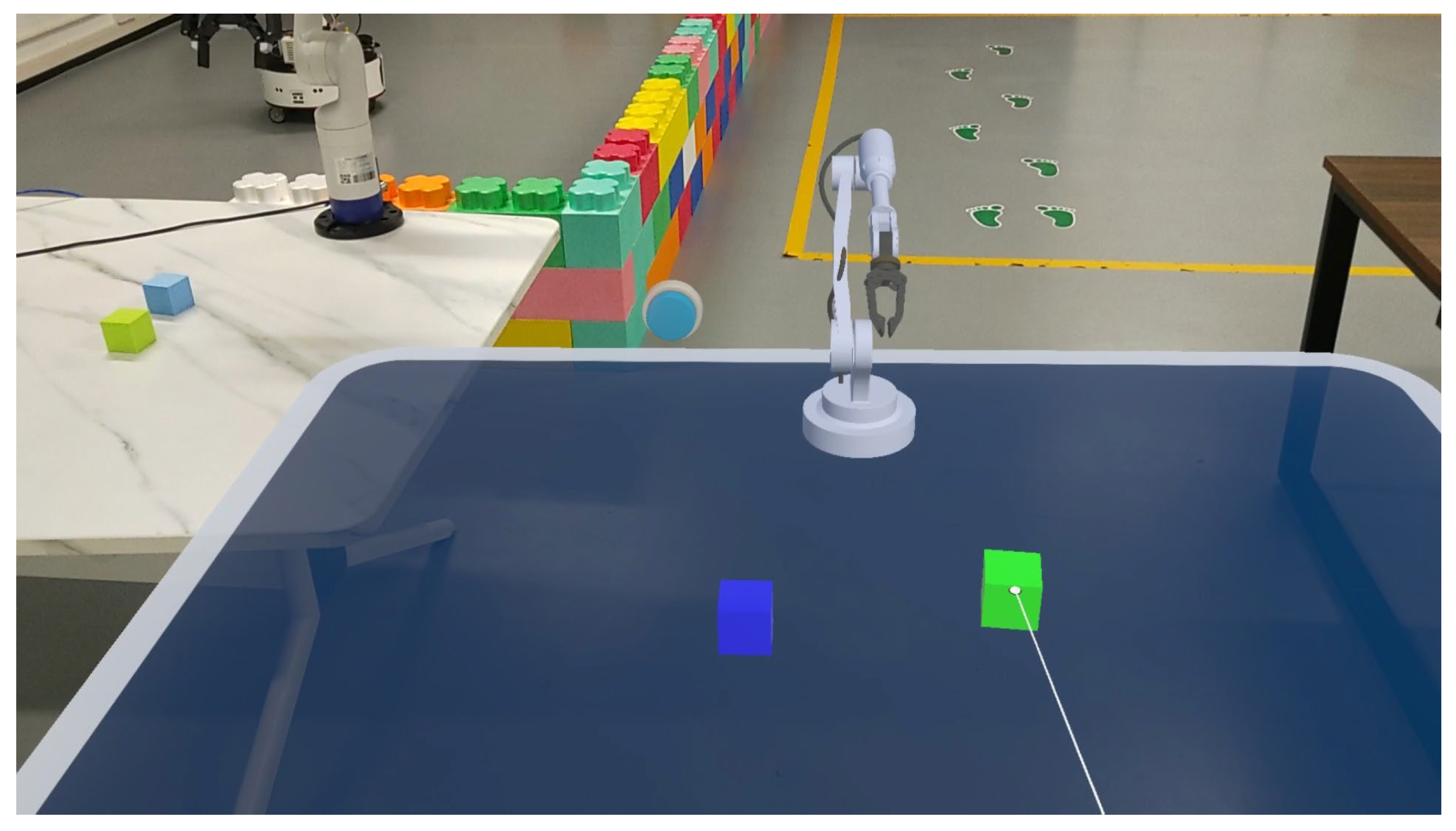
2.4. The Generation of the Virtual Scene

An application has been developed for teleoperating a robot arm. This application enables users with little or no prior experience to control the robot arm easily and reduces the technical proficiency required for tasks.
When the user starts the application, a virtual scene is generated in HoloLens2, as shown in Figure 4a. Initially, the scene includes a desktop, a robot arm, and a button. The desktop and robot arm are the digital twins of the real table and robot arm. They are used to help the user confirm the position of the robot arm and the objects. The button is used to confirm the user’s actions and prevent accidental operations.
After HoloLens2 receives the category and position of the objects, the digital twins of the objects at the corresponding position are constructed in the virtual scene, and the reference coordinate system is the base of the virtual robot arm. The digital twins of objects can be moved freely by the user, as shown in Figure 4b. The digital twins have physical properties and can simulate the operations of real senses, such as movement, collision, and falling. Users can observe the virtual scene from any angle to confirm the relative position of objects. When users observe the virtual scene in HoloLens2, users can also simultaneously observe the surrounding real environment, and the real environment includes the workspace of the robot arm. This allows users to quickly identify any unexpected events during the operation of the robot arm and press the emergency stop button to prevent risks.
Specifically, a class O b j M s g is created to save the relevant information about the objects, and the information includes the object’s name ( n a m e ) , the three-dimensional coordinate of the real objects ( p o s x , p o s y , p o s z ) , and the quaternion of the real objects ( r o t x , r o t y , r o t z , r o t w ) . In the ROS receive script, the S u b s c r i b e r ( ) function is used to receive ROS messages. When Unity receives the objects’ information from ROS, the O b j e c t P o s e N o w . A d d ( ) function is used to save the objects’ information to the dictionary O b j e c t P o s e N o w . The dictionary then uses the object’s name as the key and the three-dimensional coordinate and quaternion as the value. Then, the O b j A d d ( ) function is used to sequentially add the prefabricated 3D models of the objects to the virtual scene. The core Algorithm 1 is as follows:
Algorithm 1: ROS Subscriber
Input :   the   dictionary   of   object   O b j e c t P o s e N o w ;
1: while 1 do
2 :     o b j = S u b s c r i b e r ( )
3 :     O b j e c t P o s e N o w . A d d ( o b j . n a m e , O b j e c t M e s s a g e )
4 :     O b j A d d ( o b j . n a m e , o b j . p o s x , o b j . p o s z , o b j . p o s y )
5: end while
In the virtual scene, the user can move the digital twins of the objects to any position without affecting the real objects, as shown in Figure 5. When all digital twins have been moved to the target position, the user can press the confirmation button. After the user presses the confirmation button, HoloLens2 uses the script to select the moved digital twins. The script scans all objects in the virtual scene and calculates the difference between the current position of each object and its recorded position. Then, the script determines whether the object has been moved based on a set threshold. If the difference is less than the threshold, the object is considered not to be moved; otherwise, the current coordinates of the object are sent to ROS.
Specifically, a script is created to send data to ROS. The script iterates through all the object’s information o b j n o w in the virtual scene. The script uses the current object’s name o b j n a m e as the input and uses the O b j e c t P o s e N o w ( ) function to obtain the object’s information o b j s a v e d which is stored in the ROS receive script. Then, Equation (8) is used to determine whether the current virtual object has been moved. If any conditions are met, the current virtual object is considered to be moved.
x n o w x s a v e d > 10 5   y n o w y s a v e d > 10 5 z n o w z s a v e d > 10 5
where x n o w , y n o w , and z n o w   represent the current three-dimensional coordinates of the object in Unity, and x s a v e d , y s a v e d , and z s a v e d represent the three-dimensional coordinates of the object o b j s a v e d which are stored in the receiver script. In the virtual scene, because the data type for object coordinates is that of float and the precision of float is approximately 6–9 digits, the threshold is set to 10 5 . This ensures that objects that have not been moved are not determined as moved objects and prevents the robot arm from unnecessary actions. If identifying moved virtual objects, current three-dimensional coordinates are updated in the saved object message o b j s a v e d . Then, the object message is sent to ROS via the P u b l i s h ( ) function. The core Algorithm 2 is given as follows:
Algorithm 2: ROS Publisher
Input :   name   of   digital   twin   o b j n a m e ;
Output :   moved   digital   twin   o b j s a v e d ;
1 :   for   i = 1 , 2 , 3 , N  do
2:   o b j s a v e d = O b j e c t P o s e N o w ( o b j n a m e ( i ) )
3:    if   x n o w x s a v e d > 1 0 5   or   y n o w y s a v e d > 1 0 5   or   z n o w z s a v e d > 1 0 5  then
4:    x s a v e d = x n o w
5:    y s a v e d = y n o w
6:    z s a v e d = z n o w
7:    P u b l i s h ( o b j s a v e d )
8:   end if
9: end for
The program sends the target object’s category and destination position to ROS via the ROS-TCP-Connector. ROS subscribes to this topic through ROS-TCP-Endpoint. Then, ROS reads the current position of the target object, and the current position of the object determines the coordinates that the robot arm’s end effector needs to reach. The server uses the inverse kinematics solver, which can calculate the joint angle of the robot arm according to the position of the end effector to obtain the pose of the robot arm, and the inverse kinematics solver is provided by ROS. Subsequently, the server autonomously controls the robot arm to move to the current position of the target object and grasp it, as shown in Figure 6a. Similarly, after ROS obtains the pose of the robot arm at the destination position through the inverse kinematics solver, ROS autonomously controls the robot arm to move to the destination position, as shown in Figure 6b, and places the object at the destination position, as shown in Figure 6c. Finally, the robot arm is controlled to return to the initial position and waits for the next task, as shown in Figure 6d.

2.5. Experiment

2.5.1. Participants

MR is ultimately used to assist users, so the user experience is crucial. The experiment involved 30 participants. Twenty participants in this study were male, and ten participants were female. Twenty-four participants were between the ages of 21–25, and six participants were between the ages of 26–30. All participants were graduate students. Only one of them had previous experience with MR devices, while the others had no experience with any extended reality (XR) devices. Additionally, none of the participants had any experience with robots.

2.5.2. Experiment Setup

The test uses two different operational methods. The first is based on MR, and the second is based on the traditional method, which uses a game controller to teleoperate the robot arm and observe the workspace through a 2D display. Regardless of whether participants have previously used extended reality (XR) devices, they receive an explanation of how the HoloLens 2 device works. Then, participants have a few minutes to practice the teleoperation of the robot arm in a practice scene, in which participants can practice the different operational methods. The practice phase helps to reduce operational errors caused by unfamiliarity with the device and decreases the number of collisions. During the practice phase, participants are allowed to operate the robot arm face-to-face to quickly become familiar with the operation of the robot arm. When the participants indicate they can proficiently use the device, they can proceed with the experiment.
In the experiment scene, there are two different colored cubes on one side of the robot arm, as shown in Figure 6a. Participants need to teleoperate the robot arm to place the cubes of different colors on the other side of the robot arm, as shown in Figure 6e. During this process, participants cannot directly observe the workspace of the robot arm. When participants use MR, participants need to observe and operate the virtual scene through gesture commands to complete the task. When participants use the traditional method, they need to observe the workspace from a 2D perspective and complete the task using a game controller. During the experiment, regardless of the method used, the participants must face away from the workspace of the robot arm to prevent the participants from directly observing the workspace of the robot arm. Participants have unlimited time to complete the task, but participants are required to complete the task as efficiently as possible. The order of the two methods is randomized to mitigate potential order effects. The time of completing the task is recorded. After participants complete the tasks, they need to fill out two surveys. The experimental flowchart is shown in Figure 7.
During the experiment, participants remain at a distance from the workspace of the robot arm. A researcher closely observes the experiment process, alerts participants to any improper operations, and watches for warnings to press the emergency stop button to halt the robot arm. If the robot arm collides with an object or the table and the participants continue to perform dangerous operations, the researcher will immediately press the emergency stop button to halt all movements of the robot arm and record the number of collisions for experiment analysis. After the danger is eliminated, the experiment scene is reset to its initial configuration, and participants restart the task.

2.5.3. Measurements

The NASA-TLX [30] questionnaire is used to measure the system’s workload, and the SUS [22] questionnaire is used to measure the system’s usability.
The NASA-TLX is a widely used assessment tool for measuring the perceived workload of a specific task. It evaluates the workload in six subscales: mental demand, physical demand, temporal demand, performance, effort, and frustration. The specific contents of the six subscales are shown in Table 1. Users are asked to rate the perceived workload on each of these dimensions. The scores for the dimensions range from 0 (perfect) to 100 (failure) for performance and from 0 (low) to 100 (high) for the other five dimensions. For this assessment, the weighted measure involving pairwise comparisons between subscales is not included. The workload score is calculated as the average of the six subscales. Thus, the best workload score is 0 and the worst workload score is 100.
The SUS survey is used to measure the usability of a system. The questionnaire requires users to rate 10 statements on a 7-point Likert scale, ranging from “Strongly Disagree” to “Strongly Agree”. These statements cover various aspects of the system, such as complexity, consistency, and cumbersomeness. Like the NASA-TLX, the SUS is measured on a scale of 0 to 100. However, for SUS, 0 is the worst score, and 100 is the best score. The specific contents of 10 statements are shown in Table 2. Additionally, question 4 (“I thought that I would need the support of a technical person to be able to use this system”) and question 10 (“I needed to learn a lot of things before I could use this system”) relate to the learnability of the application, forming the learnability score and the other questions relate to the usability of the application, forming the usability score. The total score is the average of the learnability score and usability score.

3. Results

Figure 8 shows the average values of all NASA-TLX scores. As shown in Figure 8, the workload of the MR method is lower in all aspects compared to the traditional method. The MR method significantly reduced participants’ mental effort. Mental demand decreased from 45.50 with the traditional method to 18.67 with the MR method, and the mental demand for these two methods was statistically significantly different (p < 0.001). Physical demand decreased from 27.00 with the traditional method to 17.50 with the MR method, and the physical demand for the two methods was statistically significantly different (p < 0.001). Temporal demand decreased from 38.50 with the traditional method to 21.27 with the MR method, and the temporal demand for these two methods was statistically significantly different (p < 0.001). Performance demand decreased from 37.50 with the traditional method to 20.83 with the MR method, and the performance demand for these two methods was statistically significantly different (p < 0.001). Effort decreased from 48.33 with the traditional method to 26.57 with the MR method, and the effort for these two methods was statistically significantly different (p < 0.001). The frustration level decreased from 27.83 with the traditional method to 21.10 with the MR method, but the level of frustration for these two methods is statistically insignificantly different (p > 0.05).
Figure 9 shows the average scores from the SUS questionnaire. For the method proposed in this paper, users gave a total score of 80.92. On the Bangor adjective rating scale, this score corresponds to a “B” rating, categorized as EXCELLENT. In contrast, the traditional method’s score is only 63.25, which is far below our method and even below the SUS average score of 70. The proposed method achieved an average learnability score of 75.83 and an average usability score of 82.19, which is higher than the traditional method’s scores of 53.75 and 65.63, respectively. The total score, the learnability score, and the usability score for the two methods are statistically insignificantly different (p < 0.001). Table 3 shows the inferential statistics for all measures.
Finally, the proposed method can complete tasks within 2 min and significantly reduce collision compared to the traditional method, ensuring the safety of operation.

4. Discussion and Conclusions

This paper proposes a method for controlling a robot arm in an MR environment. The method uses object recognition and localization to generate digital twins of objects in corresponding locations in the virtual scene. In this virtual scene, users can specify which objects to grasp and their placement positions. Then, the server autonomously controls the robot arm to complete the grasping and placing operations. It is, thus, a technique intended to teleoperate the robot arm by interacting with an object’s digital twins. Our purpose is to develop an easy-to-use teleoperation method to enhance the teleoperation experience, allowing inexperienced users to execute a task that requires specific skills and experience. This paper also compares the proposed method to the traditional method and assesses the study results using qualitative metrics questionnaires. The results indicate that it is easy and feasible for inexperienced users to control a robot arm using the MR interface. The results also show that the proposed method reduces the workload of the teleoperation system compared to the traditional method.
In summary, our research findings substantiate the advantages of our method in the teleoperation of robot arms, including ease of use and a reduced workload. When using the method proposed in this paper for the teleoperation of robot arms, all participants agreed that the method was user-friendly, intuitive, and beneficial for the task of robot arm teleoperation. After experimenting with the equipment, they reported a sense of comfort with the method and did not perceive a significant workload, as evidenced by the NASA-TLX questionnaire data. In terms of the system’s usability and learnability, all participants demonstrated high levels of proficiency, indicating that the requirements for users to effortlessly learn and utilize the method have been satisfactorily met.
Compared to the other methods [30], the proposed method has a lower workload, and the comparative table is shown in Table 4. The other method recruited 15 participants to test and evaluate the performance of the system. As shown in Table 4, our method achieves better scores in the measures of NASA-TLX compared to other methods, especially in mental demand, physical demand, temporal demand, and performance; the workload scores were reduced by more than 50% compared to the other method. This indicates that the method proposed in this paper is superior at reducing the user’s workload.
The major limitation of the present study is motion planning. For motion planning, the method uses the default algorithm provided by ROS, which results in suboptimal motion trajectories. Future work will focus on improving the system, especially in motion planning algorithms, and increasing the variety of objects that can be grasped.

Author Contributions

Conceptualization, Y.W. and B.Z.; methodology, Y.W. and B.Z.; software, B.Z.; validation, B.Z.; formal analysis, B.Z.; investigation, B.Z.; resources, Q.L.; data curation, Q.L.; writing—original draft preparation, B.Z.; writing—review and editing, Y.W., B.Z. and Q.L.; visualization, B.Z.; supervision, Y.W. and Q.L.; project administration, Y.W. and Q.L.; funding acquisition, Y.W. and Q.L. All authors have read and agreed to the published version of the manuscript.

Funding

This research was funded by the Education Department of Jilin Province, grant number JJKH20240946KJ.

Institutional Review Board Statement

Not applicable.

Informed Consent Statement

Not applicable.

Data Availability Statement

Not applicable.

Conflicts of Interest

The authors declare no conflicts of interest.

References

  1. Manuel, M.P.; Faied, M.; Krishnan, M. A LoRa-Based Disaster Management System for Search and Rescue Mission. IEEE Internet Things J. 2024, 11, 34024–34034. [Google Scholar] [CrossRef]
  2. Zhang, Y.; Song, Z.; Yu, J.; Cao, B.; Wang, L. A novel pose estimation method for robot threaded assembly pre-alignment based on binocular vision. Robot. Comput. Integr. Manuf. 2025, 93, 102939. [Google Scholar] [CrossRef]
  3. Koreis, J. Human–robot vs. human–manual teams: Understanding the dynamics of experience and performance variability in picker-to-parts order picking. Comput. Ind. Eng. 2025, 200, 110750. [Google Scholar] [CrossRef]
  4. Wang, F.; Li, C.; Niu, S.; Wang, P.; Wu, H.; Li, B. Design and Analysis of a Spherical Robot with Rolling and Jumping Modes for Deep Space Exploration. Machines 2022, 10, 126. [Google Scholar] [CrossRef]
  5. Yuan, S.; Chen, R.; Zang, L.; Wang, A.; Fan, N.; Du, P.; Xi, Y.; Wang, T. Development of a software system for surgical robots based on multimodal image fusion: Study protocol. Front. Surg. 2024, 11, 1389244. [Google Scholar] [CrossRef]
  6. Cooper, R.A.; Smolinski, G.; Candiotti, J.L.; Satpute, S.; Grindle, G.G.; Sparling, T.L.; Nordstrom, M.J.; Yuan, X.; Symsack, A.; Dae Lee, C.; et al. Current State, Needs, and Opportunities for Wearable Robots in Military Medical Rehabilitation and Force Protection. Actuators 2024, 13, 236. [Google Scholar] [CrossRef] [PubMed]
  7. Zhang, T.; Wang, R.; Wang, S.; Wang, Y.; Zheng, G.; Tan, M. Residual Reinforcement Learning for Motion Control of a Bionic Exploration Robot—RoboDact. IEEE Trans. Instrum. Meas. 2023, 72, 7504313. [Google Scholar] [CrossRef]
  8. Dubois, A.; Gadde, L.E. The construction industry as a loosely coupled system: Implications for productivity and innovation. Constr. Manag. Econ. 2002, 20, 621–631. [Google Scholar] [CrossRef]
  9. Cai, S.; Ma, Z.; Skibniewski, M.J.; Bao, S. Construction automation and robotics for high-rise buildings over the past decades: A comprehensive review. Adv. Eng. Inform. 2019, 42, 100989. [Google Scholar] [CrossRef]
  10. Su, Y.-P.; Chen, X.-Q.; Zhou, C.; Pearson, L.H.; Pretty, C.G.; Chase, J.G. Integrating Virtual, Mixed, and Augmented Reality into Remote Robotic Applications: A Brief Review of Extended Reality-Enhanced Robotic Systems for Intuitive Telemanipulation and Telemanufacturing Tasks in Hazardous Conditions. Appl. Sci. 2023, 13, 12129. [Google Scholar] [CrossRef]
  11. Truong, D.Q.; Truong, B.N.M.; Trung, N.T.; Nahian, S.A.; Ahn, K.K. Force reflecting joystick control for applications to bilateral teleoperation in construction machinery. Int. J. Precis. Eng. Manuf. 2017, 18, 301–315. [Google Scholar] [CrossRef]
  12. Dinh, T.Q.; Yoon, J.I.; Marco, J.; Jennings, P.A.; Ahn, K.K.; Ha, C.J. Sensorless force feedback joystick control for teleoperation of construction equipment. Int. J. Precis. Eng. Manuf. 2017, 18, 955–969. [Google Scholar] [CrossRef]
  13. Vu, M.H.; Na, U.J. A New 6-DOF Haptic Device for Teleoperation of 6-DOF Serial Robots. IEEE Trans. Instrum. Meas. 2011, 60, 3510–3523. [Google Scholar] [CrossRef]
  14. Labonte, D.; Boissy, P.; Michaud, F. Comparative Analysis of 3-D Robot Teleoperation Interfaces With Novice Users. IEEE Trans. Syst. Man Cybern. Part B Cybern. 2010, 40, 1331–1342. [Google Scholar] [CrossRef]
  15. Solanes, J.E.; Muñoz, A.; Gracia, L.; Martí, A.; Girbés-Juan, V.; Tornero, J. Teleoperation of industrial robot manipulators based on augmented reality. Int. J. Adv. Manuf. Technol. 2020, 111, 1077–1097. [Google Scholar] [CrossRef]
  16. Caterino, M.; Rinaldi, M.; Di Pasquale, V.; Greco, A.; Miranda, S.; Macchiaroli, R. A Human Error Analysis in Human–Robot Interaction Contexts: Evidence from an Empirical Study. Machines 2023, 11, 670. [Google Scholar] [CrossRef]
  17. Paes, D.; Feng, Z.; Mander, S.; Datoussaid, S.; Descamps, T.; Rahouti, A.; Lovreglio, R. Video see-through augmented reality fire safety training: A comparison with virtual reality and video training. Saf. Sci. 2025, 184, 106714. [Google Scholar] [CrossRef]
  18. Madani, S.; Sayadi, A.; Turcotte, R.; Cecere, R.; Aoude, A.; Hooshiar, A. A universal calibration framework for mixed-reality assisted surgery. Comput. Methods Programs Biomed. 2025, 259, 108470. [Google Scholar] [CrossRef]
  19. Zhang, T.; Cui, Y.; Fang, W. Integrative human and object aware online progress observation for human-centric augmented reality assembly. Adv. Eng. Inform. 2025, 64, 103081. [Google Scholar] [CrossRef]
  20. Zhang, C.; Lin, C.; Leng, Y.; Fu, Z.; Cheng, Y.; Fu, C. An Effective Head-Based HRI for 6D Robotic Grasping Using Mixed Reality. IEEE Robot. Autom. Lett. 2023, 8, 2796–2803. [Google Scholar] [CrossRef]
  21. Gadre, S.Y.; Rosen, E.; Chien, G.; Phillips, E.; Tellex, S.; Konidaris, G. End-User Robot Programming Using Mixed Reality. In Proceedings of the 2019 International Conference on Robotics and Automation (ICRA), Montreal, QC, Canada, 20–24 May 2019; pp. 2707–2713. [Google Scholar] [CrossRef]
  22. Rivera-Pinto, A.; Kildal, J.; Lazkano, E. Toward Programming a Collaborative Robot by Interacting with Its Digital Twin in a Mixed Reality Environment. Int. J. Hum. Comput. Interact. 2023, 40, 4745–4757. [Google Scholar] [CrossRef]
  23. Cruz Ulloa, C.; Domínguez, D.; Del Cerro, J.; Barrientos, A. A Mixed-Reality Tele-Operation Method for High-Level Control of a Legged-Manipulator Robot. Sensors 2022, 22, 8146. [Google Scholar] [CrossRef] [PubMed]
  24. DePauw, C.G.; Univerisity, B.R.; Lehigh, A.W.; Miller, M.; Stoytchev, A. An Effective and Intuitive Control Interface for Remote Robot Teleoperation with Complete Haptic Feedback. In Proceedings of the Emerging Technologies Conference-ETC, San Diego, CA, USA, 3–6 March 2008. [Google Scholar]
  25. Girbés-Juan, V.; Schettino, V.; Demiris, Y.; Tornero, J. Haptic and Visual Feedback Assistance for Dual-Arm Robot Teleoperation in Surface Conditioning Tasks. IEEE Trans. Haptics 2021, 14, 44–56. [Google Scholar] [CrossRef]
  26. Chen, F.; Gao, B.; Selvaggio, M.; Li, Z.; Caldwell, D.; Kershaw, K.; Masi, A.; Castro, M.D.; Losito, R. A framework of teleoperated and stereo vision guided mobile manipulation for industrial automation. In Proceedings of the 2016 IEEE International Conference on Mechatronics and Automation, Harbin, China, 7–10 August 2016; pp. 1641–1648. [Google Scholar] [CrossRef]
  27. McHenry, N.; Spencer, J.; Zhong, P.; Cox, J.; Amiscaray, M.; Wong, K.C.; Chamitoff, G. Predictive XR Telepresence for Robotic Operations in Space. In Proceedings of the 2021 IEEE Aerospace Conference (50100), Big Sky, MT, USA, 6–13 March 2021; pp. 1–10. [Google Scholar] [CrossRef]
  28. Smolyanskiy, N.; González-Franco, M. Stereoscopic First Person View System for Drone Navigation. Front. Robot. AI 2017, 4, 11. [Google Scholar] [CrossRef]
  29. Rosen, E.; Whitney, D.; Phillips, E.; Chien, G.; Tompkin, J.; Konidaris, G.; Tellex, S. Communicating and controlling robot arm motion intent through mixed-reality head-mounted displays. Int. J. Robot. Res. 2019, 38, 1513–1526. [Google Scholar] [CrossRef]
  30. Su, Y.; Chen, X.; Zhou, T.; Pretty, C.; Chase, G. Mixed reality-integrated 3D/2D vision mapping for intuitive teleoperation of mobile manipulator. Robot. Comput. Integr. Manuf. 2022, 77, 102332. [Google Scholar] [CrossRef]
  31. Pace, F.D.; Gorjup, G.; Bai, H.; Sanna, A.; Liarokapis, M.; Billinghurst, M. Assessing the Suitability and Effectiveness of Mixed Reality Interfaces for Accurate Robot Teleoperation. In Proceedings of the 26th ACM Symposium on Virtual Reality Software and Technology, Virtual Event, Canada, 1–4 November 2020; p. 45. [Google Scholar] [CrossRef]
  32. Zhou, T.; Zhu, Q.; Du, J. Intuitive robot teleoperation for civil engineering operations with virtual reality and deep learning scene reconstruction. Adv. Eng. Inform. 2020, 46, 101170. [Google Scholar] [CrossRef]
  33. Sun, D.; Kiselev, A.; Liao, Q.; Stoyanov, T.; Loutfi, A. A New Mixed-Reality-Based Teleoperation System for Telepresence and Maneuverability Enhancement. IEEE Trans. Hum. Mach. Syst. 2020, 50, 55–67. [Google Scholar] [CrossRef]
  34. Nakamura, K.; Tohashi, K.; Funayama, Y.; Harasawa, H.; Ogawa, J. Dual-arm robot teleoperation support with the virtual world. Artif. Life Robot. 2020, 25, 286–293. [Google Scholar] [CrossRef]
  35. Naceri, A.; Mazzanti, D.; Bimbo, J.; Tefera, Y.T.; Prattichizzo, D.; Caldwell, D.G.; Mattos, L.S.; Deshpande, N. The Vicarios Virtual Reality Interface for Remote Robotic Teleoperation. J. Intell. Robot. Syst. 2021, 101, 80. [Google Scholar] [CrossRef]
  36. Sun, Q.; Chen, W.; Chao, J.; Lin, W.; Xu, Z.; Cao, R. Smart Task Assistance in Mixed Reality for Astronauts. Sensors 2023, 23, 4344. [Google Scholar] [CrossRef] [PubMed]
Figure 1. Interaction between the hardware models.
Applsci 15 03549 g001
Figure 2. Flowchart of the teleoperation system by interacting with objects’ digital twins.
Applsci 15 03549 g002
Figure 3. Communication settings between devices.
Applsci 15 03549 g003
Figure 4. The generation of an interactive interface in which the relative position between the virtual object and the robot arm is consistent with that between the real object and the robot arm. (a) The initial interactive interface. (b) Generating an interactive interface for virtual objects.
Applsci 15 03549 g004
Figure 5. User moves virtual objects.
Applsci 15 03549 g005
Figure 6. The action of the real robot arm. (a) The initial posture of the robot arm. (b) The grasping action of the real robot arm. (c) The movement of the real robot arm. (d) The placement of the real robot arm. (e) The resetting of the real robot arm.
Applsci 15 03549 g006
Figure 7. The flowchart of user operation in the experiment.
Applsci 15 03549 g007
Figure 8. Statistical graphs of NASA-TLX for the traditional method and our method during the task [15]. The whiskers indicate the mean +/− standard deviation, and * denotes that data are statistically significantly different, p < 0.001.
Applsci 15 03549 g008
Figure 9. Statistical graphs of SUS for the traditional method and our method during the task [15]. The whiskers indicate the mean +/− standard deviation, and * denotes the data that are statistically significantly different, p < 0.001.
Applsci 15 03549 g009
Table 1. The measures of NASA-TLX and an explanation of the measures which used to measure different kinds of burdens imposed by the method.
MeasureExplain
Mental DemandHow mentally demanding was the task?
Physical DemandHow physically demanding was the task?
Temporal DemandHow hurried or rushed was the pace of the task?
PerformanceHow successful were you in accomplishing what you were asked to do?
EffortHow hard did you have to work to accomplish your level of performance?
FrustrationHow insecure, discouraged, irritated, stressed, and annoyed were you?
Table 2. The statements of SUS and an explanation of the statements. The SUS scores reflect the overall usability.
NumberExplain
1I thought that I would like to use this system frequently
2I found the system unnecessarily complex
3I thought the system was easy to use
4I thought that I would need the support of a technical person to be able to use this system
5I found the various functions in this system were well integrated
6I thought that there was too much inconsistency in this system
7I would imagine that most people would learn to use this system very quickly
8I found the system very cumbersome to use
9I felt very confident using the system
10I needed to learn a lot of things before I could get going with this system
Table 3. Inferential statistics for all measures.
MeasureTraditional MethodOur Methodtp
MeanStd. DevMeanStd. Dev
Mental Demand45.5013.5018.6712.917.737<0.001
Physical Demand27.0012.4217.507.2743.554<0.001
Temporal Demand38.5014.6721.1713.644.659<0.001
Performance37.5015.8520.8311.844.537<0.001
Effort48.3319.7226.5718.284.359<0.001
Frustration27.8313.8921.1020.821.4490.154
Learnability53.7517.1275.8317.95−4.794<0.001
Usability65.6316.4482.1910.95−4.516<0.001
Total score63.2513.9480.929.475−5.645<0.001
Table 4. The comparative table between the proposed method and other methods [30] in NASA-TLX. MR-3DPC uses mixed reality with 3D point clouds and monocular RGB to visualize the workspace.
MeasureMR-3DPCOur Method
Mental Demand47.818.7
Physical Demand41.317.5
Temporal Demand47.7321.2
Performance50.3320.8
Effort49.6726.6
Frustration41.7321.1
Disclaimer/Publisher’s Note: The statements, opinions and data contained in all publications are solely those of the individual author(s) and contributor(s) and not of MDPI and/or the editor(s). MDPI and/or the editor(s) disclaim responsibility for any injury to people or property resulting from any ideas, methods, instructions or products referred to in the content.

