Article

Assessment of the Mechanical Properties of Low-Cost Seismic Isolators Exposed to Environmental Conditions

by
Erika D. Lemos-Micolta
1,
Isabel C. Velasco-Cuervo
1,
Ingrid E. Madera-Sierra
2,*,
Manuel Alejandro Rojas-Manzano
1,
Orlando Cundumí
1,
Edwin Patino
3,
Manuel Salmeron-Becerra
3,
Marina Lopez-Arias
3,
Shirley J. Dyke
3,4 and
Mirian Velay-Lizancos
3
1
Departamento de Ingeniería Civil e Industrial, Pontificia Universidad Javeriana Cali, Calle 18 #118-200, Santiago de Cali P.O. Box 164, Colombia
2
Departamento de Tecnología de la Construcción, Facultad de Artes Integradas, Escuela de Arquitectura, Universidad del Valle, Calle 13 # 100-00, Santiago de Cali 760032, Colombia
3
Lyles School of Civil and Construction Engineering, Purdue University, 585 Purdue Mall, West Lafayette, IN 47907-2088, USA
4
School of Mechanical Engineering, Purdue University, 585 Purdue Mall, West Lafayette, IN 47907-2088, USA
*
Author to whom correspondence should be addressed.
Appl. Sci. 2025, 15(7), 3467; https://doi.org/10.3390/app15073467
Submission received: 20 December 2024 / Revised: 27 February 2025 / Accepted: 14 March 2025 / Published: 21 March 2025
(This article belongs to the Special Issue Earthquake Prevention and Resistance in Civil Engineering)

Abstract

:
In Colombia, low-cost unbonded fiber-reinforced elastomeric isolators made from natural rubber (UN-FREI) and recycled rubber (UR-FREI) have emerged as a solution to mitigate damage in low-rise structures during earthquakes. However, their performance under environmental degradation caused by factors such as carbon dioxide, saltwater, relative humidity, and UV radiation has not been sufficiently studied. These agents can compromise the mechanical properties of rubber, affecting its ability to dissipate energy. This study evaluates the performance of these isolators under different environmental conditions through the initial characterization of rubber, mechanical testing of small-scale prototypes exposed to controlled environments, and seismic analysis of an isolated structure. Modification factors (λ(ae,max) and λ(ae,min)) were determined to quantify the impact of degradation on structural behavior. The results indicate that UN-FREI specimens are more sensitive to environmental conditions than UR-FREI specimens, whereas the mechanical properties of UN-FREI small-scale prototypes remain more stable compared to those of UR-FREI. This leads to increased drift, base shear, and demand-to-capacity ratios (DCRs) in the structural analysis. The findings emphasize the need for experimental testing of isolators to establish modification factors that accurately reflect the effects of environmental conditions on structures throughout their service life.

1. Introduction

Earthquake engineering research has promoted the development of seismic control elements to mitigate the impact of earthquakes at various economic and social levels [1,2,3]. Among these, elastomeric isolators have demonstrated significant performance improvements. These devices decouple buildings from their foundations, reducing the vibrations transmitted from the ground to structural elements and consequently minimizing damage to the structure during an earthquake [1,4,5,6,7,8,9,10,11,12].
Studies have analyzed the performance of low-cost unbonded fiber-reinforced elastomeric isolators (UFREIs) [13,14], while Madera-Sierra [15] and Ortega Escobar [16] have investigated the development of these devices in Colombia. These isolators are made from natural rubber (UN-FREIs) and a rubber compound recycled from used vehicle tires (UR-FREIs). In general, the reduced cost of these isolators is attributed to the selection of materials that are readily available in the country, allowing for local fabrication and eliminating the need for imports [15]. Additionally, implementing these control elements in low-rise buildings could reduce repair costs and lost profits after a seismic event [15]. Full-scale experimental and numerical studies of fiber-reinforced elastomeric isolators (UFREIs) [17] provide valuable insights into their mechanical behavior under bidirectional excitation and the seismic response of a reinforced concrete building isolated with UFREIs.
The physicochemical degradation of cementitious materials by agents such as carbon dioxide (CO2) in the atmosphere [18,19], saltwater in coastal areas [20,21,22]; and relative humidity are examples of current exposure conditions that have not been studied in low-cost seismic isolators, despite their known impact on reducing the service life of conventional concrete structures [18,19].
Since UN-FREIs and UR-FREIs remain installed in buildings for several years, it is necessary to determine whether the environmental conditions responsible for degradation in conventional structures could also affect the mechanical properties of these seismic control devices and compromise their structural function. Additionally, elastomers and polymers undergo photodegradation due to ultraviolet (UV) radiation from the sun [23,24,25]. However, studies on the influence of this factor have been largely limited to bridge rubber bearings [26,27], without considering the potential exposure of UN-FREIs and UR-FREIs to UV rays during installation or storage.
As a result, there is limited knowledge about the influence of these environmental conditions on the behavior of isolators throughout their service life and their implications for the response of an isolated building or bridges with deteriorated isolators [28].
The importance of elastomeric isolators in earthquake engineering has led researchers to focus on analyzing the degradation of rubber’s mechanical properties under specific environmental conditions over time. For example, standardized tests such as ASTM D573-04 [29] establish a method for evaluating rubber deterioration when exposed to elevated temperatures in a hot air oven. The objective is to determine the effects of thermal aging on the physical and mechanical properties of rubber compounds.
Some studies [26,27] have developed tests to assess the degradation of natural rubber and high-cushion rubber caused by factors such as thermal oxidation, ultraviolet exposure, ozone, low-temperature ozone, saltwater, and acid rain. These studies concluded that thermal oxidation at 70 °C is the dominant aging process, affecting rubber performance and negatively influencing the seismic response of isolated bridges. Research on natural rubber has shown that thermal oxidation increases stiffness [30]. Conversely, exposure to low temperatures induces the crystallization of natural rubber, which can decrease the material’s equivalent horizontal stiffness and damping over a prolonged period [31]. Other studies have focused on developing seismic isolators using recycled tire rubber [16,32,33].
The use of sustainable materials in seismic isolation has gained attention, as demonstrated in studies on reactivated EPDM compounds for fiber-reinforced elastomeric isolators [34,35]. These studies offer an alternative approach by integrating recycled materials and assessing thermal aging conditions in a hot oven. Additionally, Losanno, Palumbo, et al. [36] conducted aging tests on recycled tire rubber specimens, concluding that horizontal stiffness increases after six weeks of aging. In Colombia, UN-FREIs and UR-FREIs have only been tested under normal operating conditions. Therefore, further studies are needed to characterize the behavior of rubber compounds throughout natural degradation processes. This will help establish design parameters and recommended precautions to minimize damage over their service life.
Due to the limited knowledge regarding the manufacturing, handling, storage, and installation conditions of seismic isolators, it is essential to characterize the mechanical behavior of UN-FREIs and UR-FREIs under different environmental conditions. Based on this, the present study examines how exposure to environmental factors such as relative humidity, ultraviolet radiation, saltwater, and CO2 affects the mechanical properties of natural rubber and recycled rubber compounds. Additionally, the study investigates the impact of some of these environmental conditions on the mechanical properties of small-scale prototypes of low-cost seismic isolators developed in Colombia.
The seismic response of base-isolated structures depends on the mechanical properties of the isolation devices, requiring their variability to be considered in the design process. Seismic codes address this issue through upper and lower bound analyses or property modification factors (λ-factors) when experimental data are not available, including factors for environmental degradation (λae,max and λae,min) [37].
The environmental modification factors λae,max and λae,min were determined based on changes in the properties of the prototypes to subsequently model the structure with and without these factors. Calabrese et al. [38] exposed fiber-reinforced bearings (FRBs) to heat aging and compared the response of a four-story base-isolated building using FRBs and high-damping rubber (HDRB) isolators. Both the new and aged states of the devices were considered, concluding that stiffness increases over time, reducing the effectiveness of isolation and limiting deformation, with this effect being more pronounced in FRBs.
Determining the changes in the properties of UN-FREIs and UR-FREIs will improve the prediction of the performance of isolated buildings under seismic loads, providing key information to manufacturers. This understanding will contribute to guidelines on the use and storage of these materials, minimizing potential efficiency losses during their service life.

2. Experimental Development

This research analyzed two materials for manufacturing low-cost UFREIs: (i) a high-damping natural rubber (UN-FREI) developed in collaboration with Surtidor Industrial S.A. [1], and (ii) a compound made of recycled tire rubber particles bonded with a polyurethane binder (UR-FREI), produced by Occidental de Cauchos and funded by a research project at Pontificia Universidad Javeriana Cali (PUJC) [39]. Test specimens were fabricated according to standards, and small-scale prototypes were created based on the design of a target building [7].

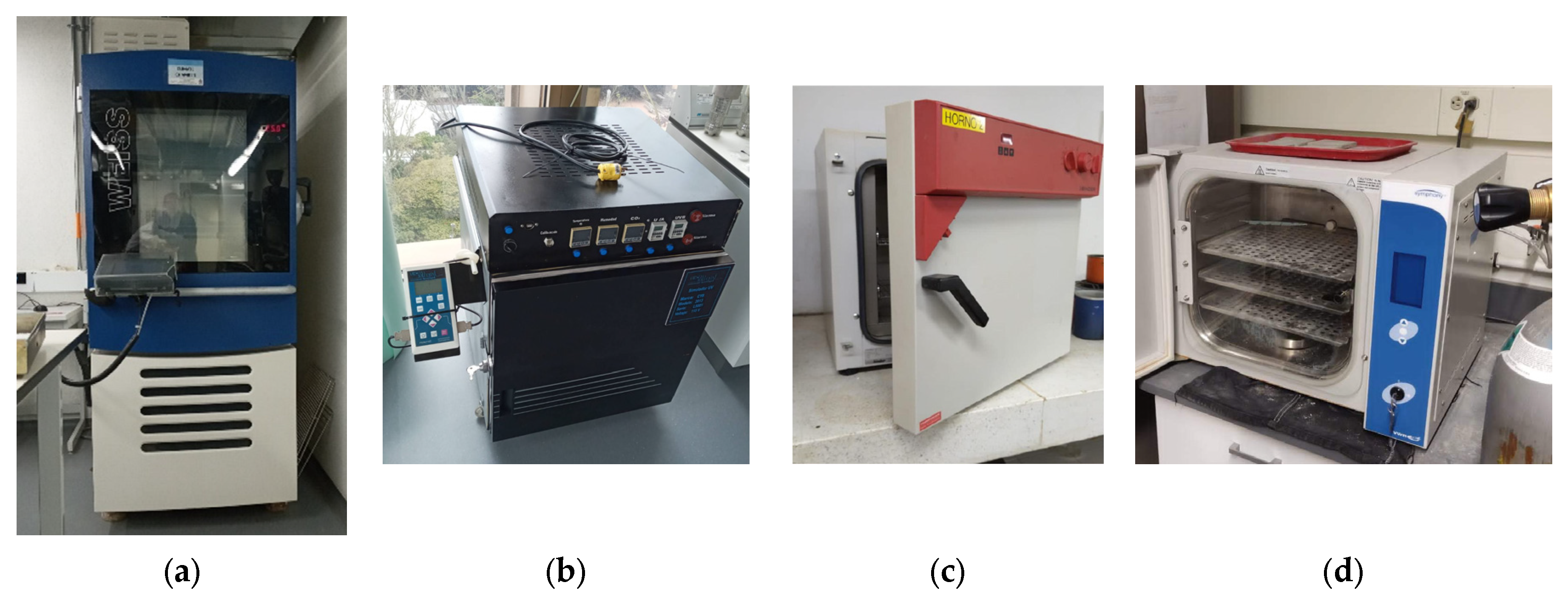
2.1. Exposure to Environmental Conditions

2.1.1. Relative Humidity (RH)

Samples were placed in a WEISS climatic chamber (Figure 1a) at the Civil Engineering Department of Pontificia Universidad Javeriana Bogotá (PUJB) under 85% RH and 25 °C, simulating conditions of high-humidity, high-seismic-risk zones such as Chocó, Colombia. Periodic mass changes were monitored using a precision balance (0.1 mg and 0.1 g accuracy). Water content (Mt) was calculated as the percentage of mass gained (Equation (1)),
M t % = m t m 0 m 0     100 %
where mt is the mass of the sample after time t, and m0 is the initial mass of the sample, with measurements taken daily for up to 30 days.

2.1.2. UV Radiation

Samples were exposed to UV radiation in an accelerated aging chamber with UVA black light lamps (340 nm, 13 W/m2, 40 °C) at PUJB (Figure 1b). Due to irradiance intensity degradation over time [40], a short exposure period was selected to ensure uniform radiation. Based on previous studies [41,42]; degradation can occur within hours; thus, specimens were removed after 5 and 9 days.

2.1.3. Saltwater (SW)

To simulate environmental conditions in coastal, high-seismic-risk areas like Chocó, specimens underwent alternating immersion in a 5% sodium sulfate solution and drying at 40 °C. This process, common in degradation studies of concrete [20] and polymers [43], lasted 16 days: 5 days of immersion, 7 days of drying, followed by another 4 days of immersion (Figure 1c). Mechanical tests were conducted at PUJC at each stage.

2.1.4. Accelerated Carbonation (CO2)

Due to the complexity of CO2 diffusion in concrete, accelerated carbonation tests are conducted at controlled CO2 levels (1–100%) ([44,45,46,47]. In this study, small-scale prototypes were exposed to 20% CO2 for 10 days in an accelerated carbonation chamber (Figure 1d) at the Pankow Materials Laboratories, Lyles School of Civil Engineering (Purdue University), followed by mechanical testing.

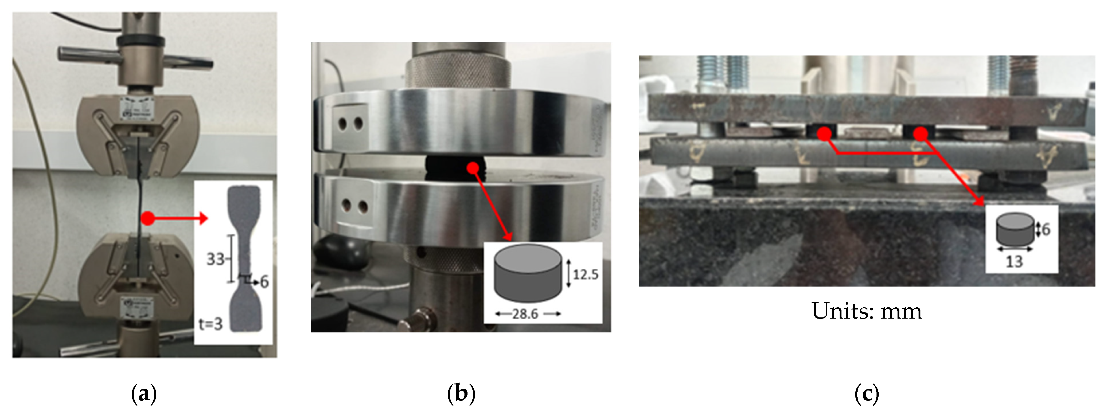
2.2. Mechanical Characterization of Specimens

The methodology from ASTM D412-16 [48] was followed to determine the maximum tensile stress. Specimens were secured in an Instron universal tensile testing machine at the PUJB laboratories, equipped with a 50 kN load cell (Figure 2a). UN-FREI specimens were tested at 500 mm/min, while UR-FREI specimens were tested at 50 mm/min to allow greater elongation before failure [16].
Specimens for compressive stress determination were prepared according to ASTM D575-91 [49] and tested in an Instron universal compression testing machine at PUJB (Figure 2b). Three successive loading–unloading cycles were performed at 12 mm/min. The first two cycles reached 50% vertical deformation for conditioning, and the third cycle recorded the load required to reach 70% deformation.
ASTM D395-18 [50] was used to evaluate deformation under constant compressive stress (Figure 2c). Before testing, the specimens’ heights were measured and then placed in an oven at 70 °C for 22 h, limiting deformation to 25% of their initial height. Thirty minutes after removal, height measurements were taken again. The residual compression (CB) was calculated (Equation (2)), where CB is expressed as a percentage of the original deflection, t0 is the original thickness, ti is the final thickness, and tn is the spacer bar thickness.
C B = ( t 0 t i ) ( t 0 t n ) × 100
Two assembly types were used to determine shear modulus and damping ratio through cyclic shear tests. UN-FREI specimens followed the setup in Figure 3a, with an 8.6 mm thickness and a rectangular cross-section of 29.5 mm × 38.4 mm. UR-FREI specimens (Figure 3b) were cylindrical, 28.6 mm in diameter, and 12.5 mm in height, and were placed under compressive stress to prevent slipping.
Tests were conducted using an MTS universal hydraulic testing machine at PUJB and an Instron universal testing machine at PUJC, applying 5 s and 9 s load periods, respectively. Since the shear modulus and damping ratio of UN-FREI are independent of the load period [1], both periods were also applied to UR-FREI for comparison. The procedures from ATC-17 [51] and ASTM D4014-03 [52] were followed.
The material deformations tested were 10%, 20%, 30%, 40%, 50%, 75%, 100%, and 150%, with ten cycles applied at each deformation level. However, although the full protocol was executed, results are presented for a strain of 30% because the UR-FREI specimens were damaged at higher strain levels.

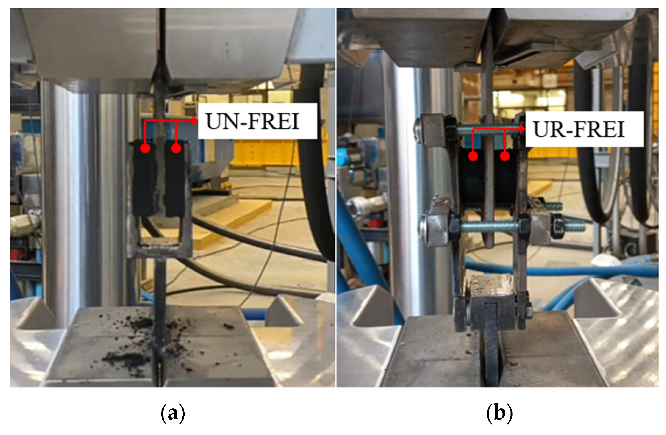
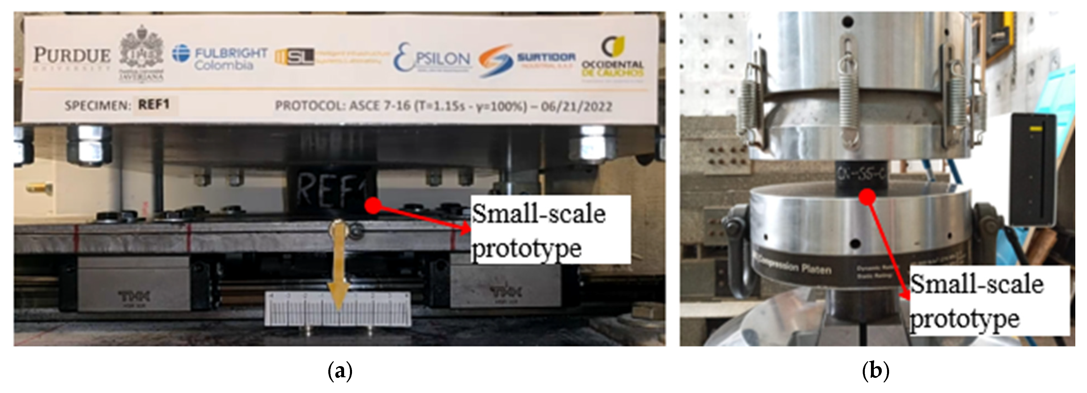
2.3. Mechanical Characterization of Small-Scale Prototypes

The dimensions of the small-scale prototypes were determined following the methodology of Losanno et al. [7,8] for both materials. The structure consisted of four columns, each subjected to a 19.25 kN applied weight. The scaled design period of the isolated structure was 1.15 s, with a nominal lifetime of 100 years. Seven seismic records representative of Italian regions were used. The resulting prototype dimensions are shown in Figure 4 [8].
Two tests were performed. In the first shear compression test, a horizontal displacement protocol was applied following Madera-Sierra’s [15] recommendations (Figure 5a). Six deformation levels were tested, namely, 25%, 50%, 67%, 100%, 100%, and 75% of the maximum chosen deformation (29 mm) with a period of 1.15 s (Figure 6a). The test was conducted at Purdue University’s Intelligent Infrastructure Systems Laboratory (IISL).
The second cyclic compression test was conducted in three phases to measure displacements under a variable compression load (Figure 5b). First, a compressive load was applied at 0.01 mm/s until reaching the design load of 19 kN. Then, three cycles were performed at ±30% of the design load at 0.05 mm/s. Finally, the compression load was fully removed at 0.01 mm/s (Figure 6b). This test was conducted at PUJB laboratories.

2.4. Characteristics of the Isolated Building

The residential building presented by Madera-Sierra [15] was used as the reference structure for the natural and recycled rubber isolators (Figure 7a).
Based on the mechanical test results of small-scale prototypes, the horizontal stiffness, vertical stiffness, and damping properties of the modeled isolators were adjusted to reflect the effects of environmental exposure. The seismic response of the building with unexposed isolators was then compared to that of isolators subjected to environmental conditions, analyzing the maximum total displacement (DTM).
It should be emphasized that, currently, there is no regulation in Colombia specifying the design of seismic isolators. Therefore, the recommendations established by Madera-Sierra [15] for the design of elastomeric fiber-reinforced isolators disconnected from the structure (UFREIs) were followed for the calculation of vertical stiffness. These recommendations include considerations from NSR-10 [53], FEMA 450 [54], and other authors referenced therein.
Figure 7 and Table 1 show the typical characteristics of this structure without considering the modification factors of properties caused by environmental conditions (λae,max and λae,min). This isolated building was used to model the effect of changes in the properties of the UN-FREI and UR-FREI isolators to compare the building’s response.
ASCE 7-16 [55] allows a response spectrum analysis to be performed, provided that certain conditions are met: the isolated structure must be located on a Site Class of type A, B, C, or D; the effective period at maximum displacement must not exceed 5.0 s to prevent excessive flexibility and high displacements; the height from the base level must be less than 19.8 m; the damping associated with the maximum displacement must be less than or equal to 30%; and the structure must not exhibit irregularities in plan or height.
Since the analyzed structure meets these criteria, the response spectrum corresponding to Zone 2 of the seismic microzonation of the city of Cali, which is similar to Site Class D, was selected (Figure 7b). The accelerations were multiplied by a factor of 1.5 to account for a return period of 2475 years (Figure 7b). The structural analysis was carried out using ETABS v20.0.0 software. For the calculation of seismic forces, a mass source composed of 100% dead load and 50% live load was defined.
Table 2 presents a summary of the geometry of the UN-FREI and UR-FREI isolators and the final properties for DTM introduced in ETABS to model the building with rubber base isolators.

3. Results and Discussion

The fabricated UN-FREI and UR-FREI specimens were exposed to different environmental conditions, and the results were compared with reference specimens, referred to as REF.

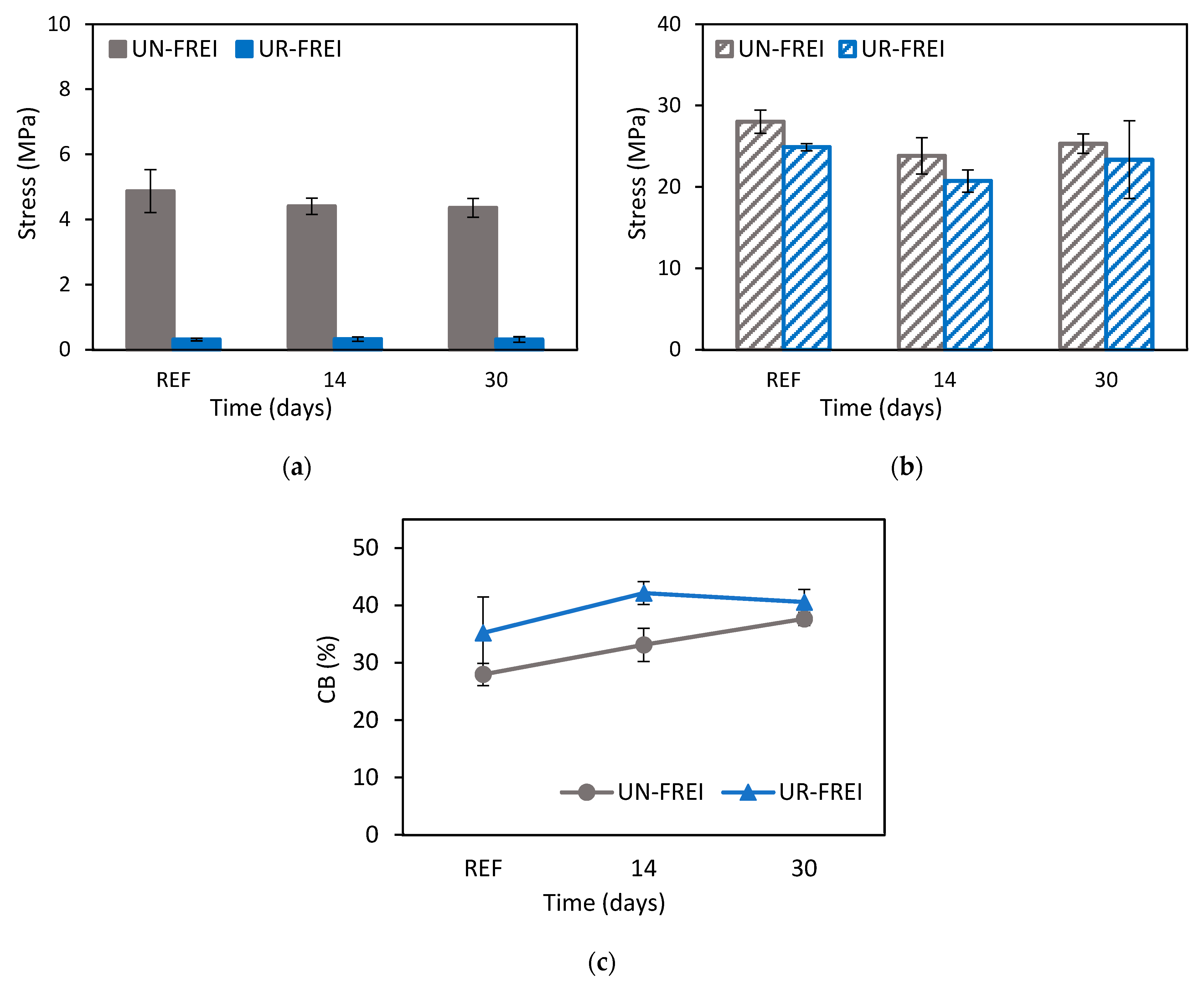
3.1. Mechanical Characterization of Specimens

Exposure to RH, UV radiation, saltwater, and CO2 was considered; however, the predominant environmental conditions are RH and CO2. Therefore, these two conditions were evaluated on the reduced-scale prototypes to obtain the property modification factors (λae,max y λae,min) and apply them for modeling the structure. The accelerated carbonation chamber is located at Purdue University; for this reason, CO2 tests were only performed on small-scale prototypes.

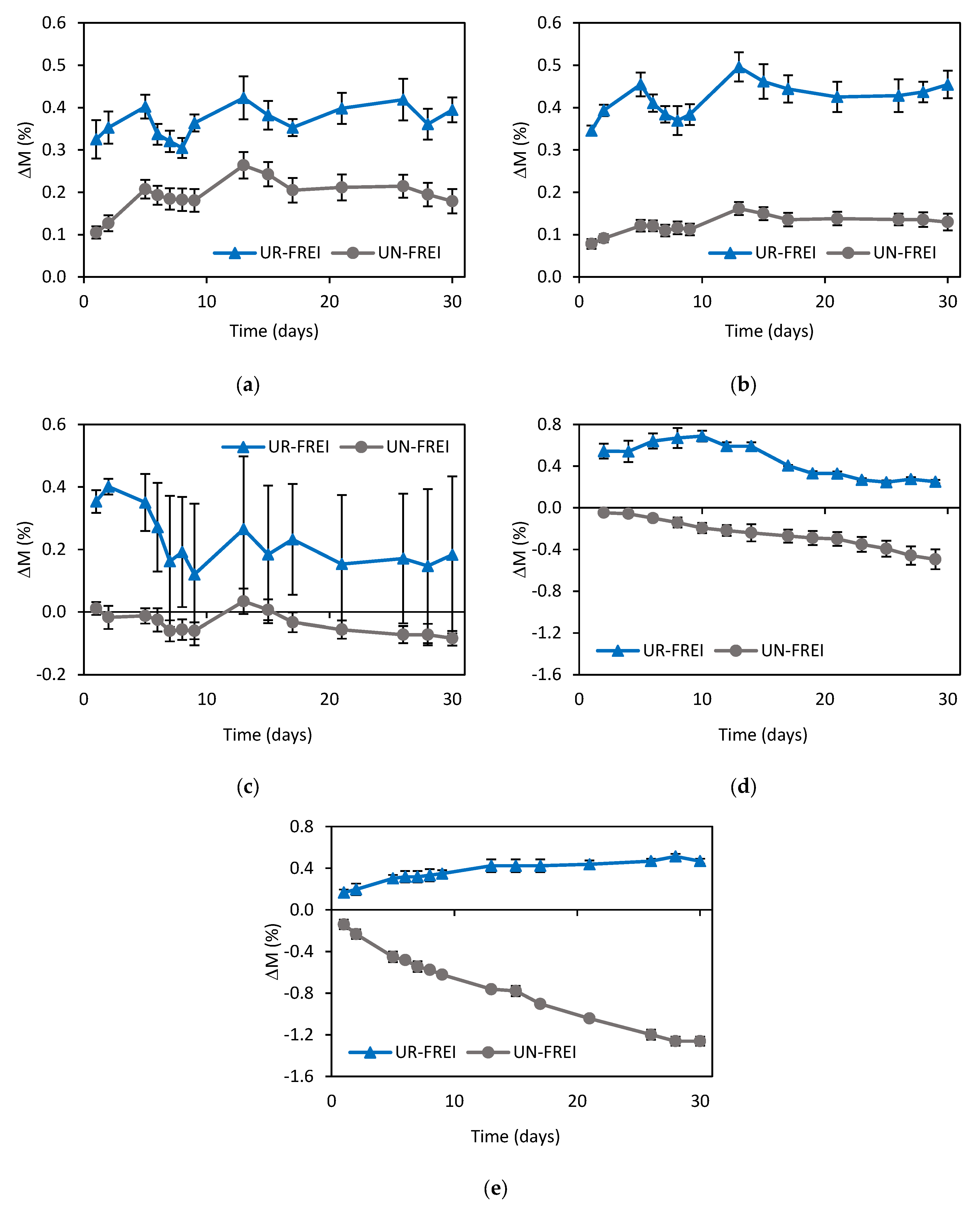
3.1.1. Relative Humidity (RH)

Figure 8 presents the mass gain curves as a function of the number of days of exposure at 85% RH for the manufactured samples. In general, the UR-FREI specimens exhibited a higher mass gain compared to the UN-FREI specimens from the beginning to the end of the exposure period. The porosity of the recycled rubber compound may be directly related to the material’s water absorption capacity.
Furthermore, the results show that the stabilization of mass gain during exposure depends on the size and shape of the specimens. While the tension (Figure 8a) and compression (Figure 8b) specimens reach stabilization after 20 days, this trend is not maintained for the prototypes (Figure 8d,e). In addition, the results of the compression set test exhibited greater dispersion in the recycled rubber material (Figure 8c), which comprised the smallest-sized samples evaluated. For the prototypes (Figure 8d,e), a mass gain occurred in the UR-FREI samples as expected, whereas the UN-FREI samples lost mass throughout the exposure period. Processes such as hydrolysis could result in the breaking of chemical bonds, allowing the release of substances and, consequently, a decrease in the material’s mass [56].
The tensile stress of the UN-FREI and UR-FREI specimens is shown in Figure 9a for 500% and 7% strains, respectively. The UN-FREI specimens were tested up to the maximum displacement capacity of the testing machine; however, they did not reach failure, whereas all UR-FREI specimens failed at approximately 7% of their initial length. The tensile strength of UR-FREI was lower than that of UN-FREI in all evaluated cases. For the reference specimens, UR-FREI reached only 6.4% of the tensile strength of UN-FREI. This behavior occurred because the recycled rubber particles exhibit low cohesion, facilitating the early failure of the material.
The RH condition resulted in a reduction in the tensile strength of the UN-FREI specimens by 9.50% and 10.48% at 14 and 30 days, respectively, indicating that as exposure time increases, strength loss slightly increases. Exposure to high RH can increase the brittleness of polymers compared to low RH because water absorption affects chemical bonds and weakens the polymer structure [56]. In the UR-FREI samples, tensile strength increased by 4.02% at 14 days but decreased by 0.09% at 30 days. Thus, there is no clear evidence of any significant effect of RH, possibly due to the low cohesion of the recycled rubber particles.
Figure 9b shows the compressive stress required to reach a deformation of 70% of the initial height in the UN-FREI and UR-FREI specimens. In general, the UR-FREI specimens, which exhibited higher water absorption and greater porosity due to the heterogeneous structure of the recycled rubber sample (Figure 8b), demonstrated lower strength than the UN-FREI specimens. The UN-FREI specimens exposed to RH had 15.00% and 9.67% less compressive strength than the reference value at 14 and 30 days, respectively, while the UR-FREI specimens showed a strength reduction of 16.72% and 6.23%, respectively. This result indicates that exposure to RH leads to a loss of stiffness in the materials, contrasting with the tensile test results.
Finally, the residual compression of the UN-FREI and UR-FREI specimens is presented in Figure 9c. For both materials, RH exposure led to an increase in the permanent deformation of the material. For UN-FREI, the deformation increased by 18.42% and 34.63%, while for UR-FREI, it increased by 19.74% and 15.25% at 14 and 30 days of exposure, respectively. The recycled rubber composite exhibited greater deformation under prolonged periods of applied load.
Regarding the cyclic shear test, data collection was limited to 30% deformation to determine the shear modulus G (Figure 10a) and the damping ratio β (Figure 10b), due to the unstable behavior of the UR-FREI specimens, which were damaged at higher deformations. The test was performed with a period of 5 s.
In general, the shear modulus and damping ratio of UR-FREI were higher than those of UN-FREI, similar to the findings presented by Losanno, Palumbo, et al. [36]. It was observed that exposure to RH for 30 days contributed to a loss in stiffness in the materials, which aligns with the tensile and compressive test results. RH exposure led to a decrease in the shear modulus of the UN-FREI and UR-FREI specimens by 23.38% and 4.17%, respectively (Figure 10a). Similarly, a reduction in damping of 2.67% for UN-FREI and 11.14% for UR-FREI was observed under the same test conditions (Figure 10b).

3.1.2. UV Radiation

Figure 11a presents the tensile strength of UN-FREI and UR-FREI specimens exposed to UV radiation at 500% and 7% strains, respectively. UV radiation caused an increase in the tensile strength of UN-FREI by 20.70% at 5 days and 39.65% at 9 days of exposure. The formation of new bonds could increase stiffness and initial deformation resistance; however, it could also make the rubber less elastic and reduce its ability to withstand high stresses before rupture [27,57];. Conversely, after 9 days of exposure, the UR-FREI samples exhibited a tensile strength 18.27% lower than the reference value.
The compressive stress at 70% deformation of the UN-FREI and UR-FREI specimens is shown in Figure 11b. Contrary to the results observed under RH exposure, the UR-FREI specimens exhibited higher compressive strength values than the UN-FREI specimens when exposed to UV radiation. The UN-FREI specimens experienced a strength decrease of 4.28% and 17.26% at 5 and 9 days of exposure, respectively. Conversely, the UR-FREI samples showed an increase in compressive strength of 13.93% at 5 days and 1.65% at 9 days. In general, after 9 days of exposure, both materials experienced a decline in strength compared to the initial days of UV radiation exposure.
The residual compression of the UN-FREI and UR-FREI specimens is shown in Figure 11c. UV radiation caused a reduction in deformation for both materials. For UN-FREI, the reduction was 18.58% at 5 days and 19.33% at 9 days of exposure, while for UR-FREI, it was 22.07% at 5 days and 12.04% at 9 days.
The cyclic shear test was conducted with a period of 5 s. In the UN-FREI samples, the shear modulus remained constant after 5 days of UV exposure but decreased by 17.88% after 9 days. In contrast, the UR-FREI samples exhibited a 5.62% increase in the shear modulus at 5 days, followed by a slight decrease of 1.03% at 9 days (Figure 12a). Regarding the damping ratio (Figure 12b), after 9 days of exposure, the UN-FREI samples showed an 8.83% increase in damping, whereas the UR-FREI samples exhibited a 1.80% decrease.

3.1.3. Saltwater (SW)

Tensile strength values are reported in Figure 13a for UN-FREI and UR-FREI specimens exposed to saltwater for 500% and 7% strains, respectively. In the first days of immersion, the UN-FREI specimens exhibited a decrease in tensile strength of 0.92% (day 5), followed by an increase of 22.82% due to the drying process (day 12). However, with further immersion in saltwater, the strength gain was reduced to 7.09% (day 16). This suggests that the drying process increases stiffness at 500% deformation, likely due to the test temperature, whereas immersion in saltwater decreases tensile strength as the material becomes more flexible due to water absorption.
In contrast, the UR-FREI specimens displayed the opposite behavior. Initial immersion led to an increase in tensile strength of 48.56% (day 5), followed by a decrease of 3.69% after drying (day 12), and finally, with re-immersion, the strength gain was reduced to 12.93% (day 16). Overall, repeated cycles of saltwater immersion and drying could increase the material’s tensile strength over time, but its deformation capacity would be reduced [58].
Figure 13b shows the compressive stress required to achieve 70% deformation in the UN-FREI and UR-FREI specimens. Contrary to the compressive values observed in specimens exposed to RH, the UR-FREI specimens exhibited higher strength than the UN-FREI specimens. The UN-FREI specimens exposed to saltwater experienced a strength loss of 34.38%, 41.56%, and 41.05% at 5, 12, and 16 days of testing, respectively. However, the strength values of UR-FREI followed an increasing trend, transitioning from a loss of 14.23% at day 5 to a gain of 8.39% at day 16.
Regarding residual compression (Figure 13c), exposure to saltwater increased the deformation of both the UN-FREI and the UR-FREI specimens, reaching a CB of 34% and 46% at the end of the exposure period, respectively.
The cyclic shear test was conducted with a period of 9 s due to the capacity limitations of the laboratory machine used. With increased saltwater exposure, the shear modulus increased by 12.84% in UN-FREI and 3.62% in UR-FREI at 16 days of exposure (Figure 14a).
Regarding the damping ratio, it is evident that increasing the test period decreased the damping ratio of both materials compared to the tests conducted under RH and UV radiation exposure, which were performed with a period of 5 s. At 30% strain, the difference in damping between the reference samples tested at 5 and 9 s was 21%. FEMA 450 [54] specifies a maximum difference of 15% in properties to demonstrate the independence of rubber behavior from the test period. Therefore, under the conditions of this study, the observed difference is slightly higher.
This behavior is similar to that reported by Madera Sierra et al. [1], who concluded that as the test period increased, the damping ratio decreased by up to a maximum of 8%. With increased exposure to saltwater, the damping ratio decreased by 25.77% in UN-FREI and 11.57% in UR-FREI (Figure 14b) compared to the reference value.

3.1.4. Summary of Specimen Results

To evaluate the results obtained from exposing the materials to the considered environmental conditions, four ranges were defined, using a 20% change in properties as the critical value. This threshold was based on ASCE 7-16 [55], specifically, Chapter 17.8.4, Test Specimen Adequacy, which allows up to a 20% change in the effective stiffness of tested prototypes.
Initially, the results from each day of exposure were compared with the reference values. Then, for each type of exposure and each test, the values with the greatest change were selected, regardless of the test duration. This methodology was used to establish the nomenclature presented in Table 3.
The criteria in Table 3 were applied to the sample results and are presented in Table 4. In general, it was observed that more properties of the UN-FREI specimens fell within the critical range, whereas a greater number of properties in the UR-FREI specimens were classified in the severe range. This suggests that UR-FREI, being a more rigid and heterogeneous material with particles bound by a binder, is less vulnerable to changes in its properties compared to UN-FREI in small specimens.
A high shear modulus in the UN-FREI will increase the stiffness of the isolator, which in turn leads to a shorter period and higher accelerations, potentially increasing drifts and shear forces in the isolated building. Additionally, higher damping helps reduce the accelerations considered in the response spectrum [59].

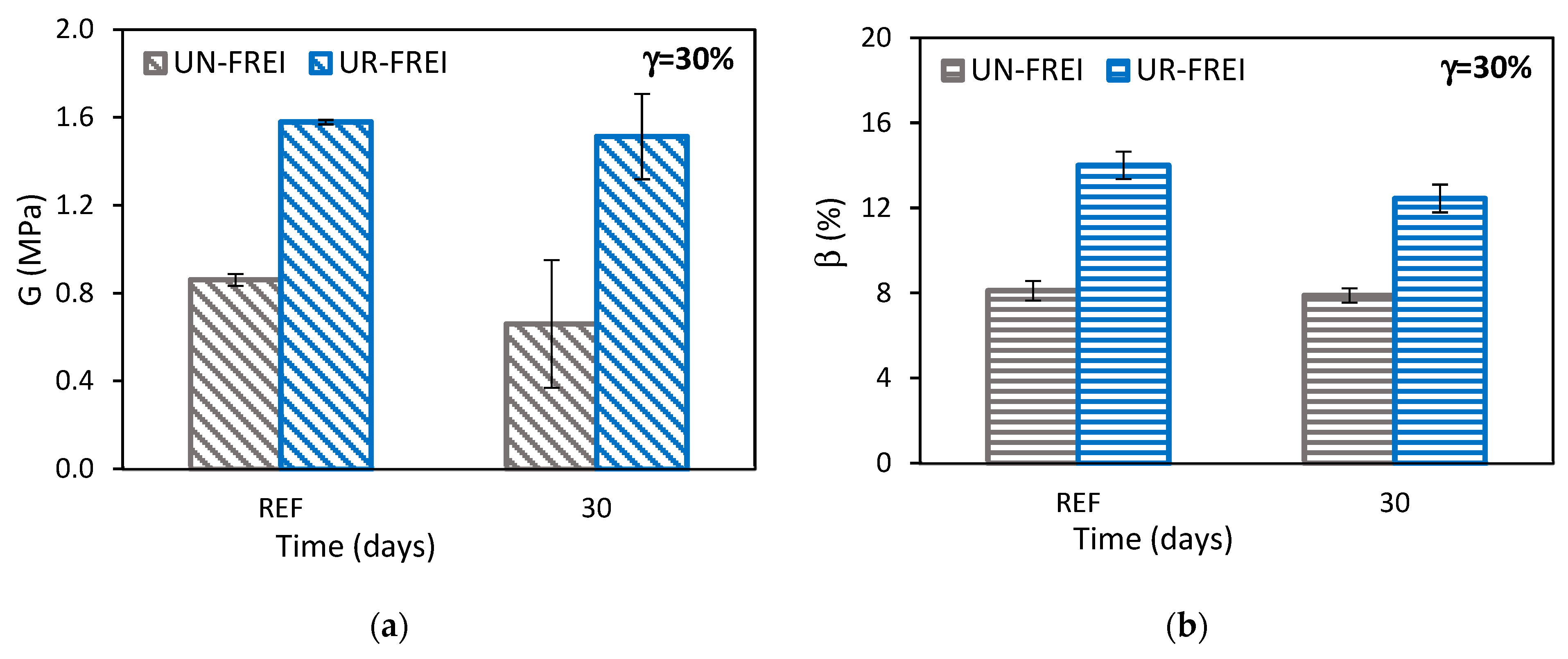
3.2. Mechanical Characterization of Small-Scale Prototypes

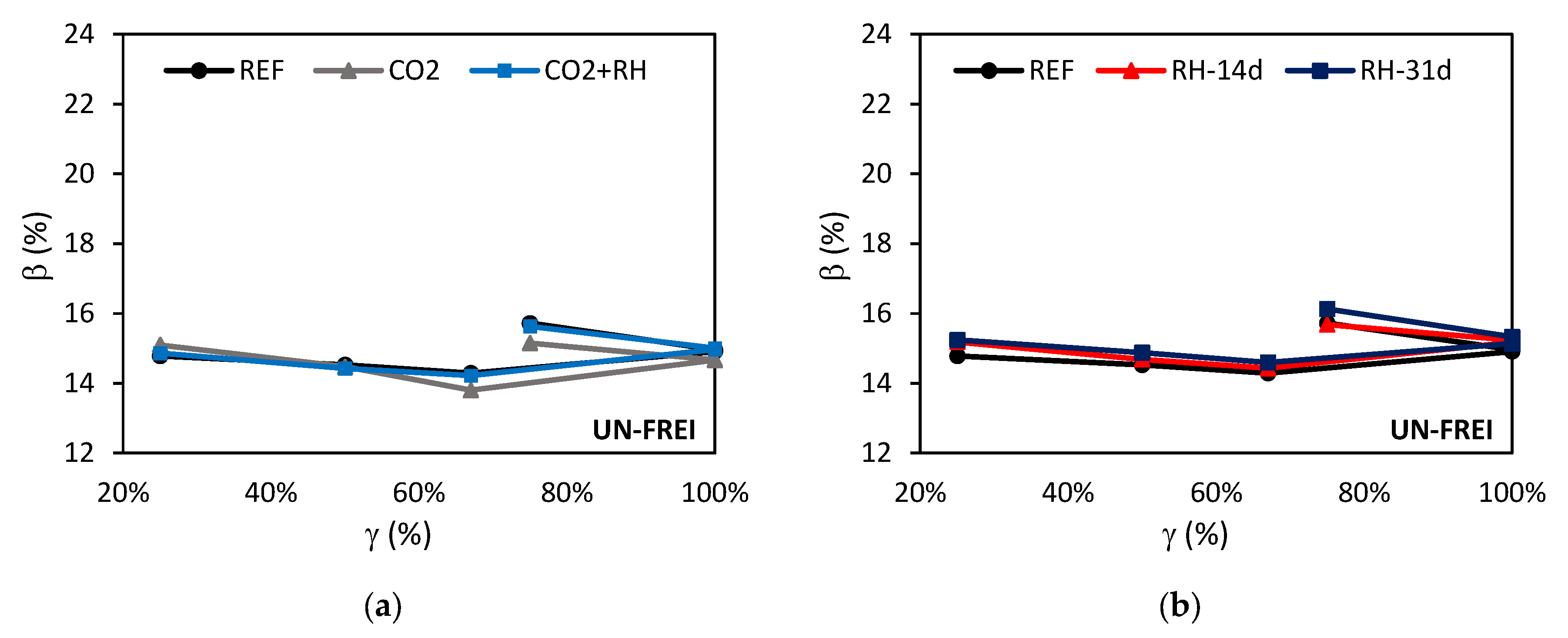
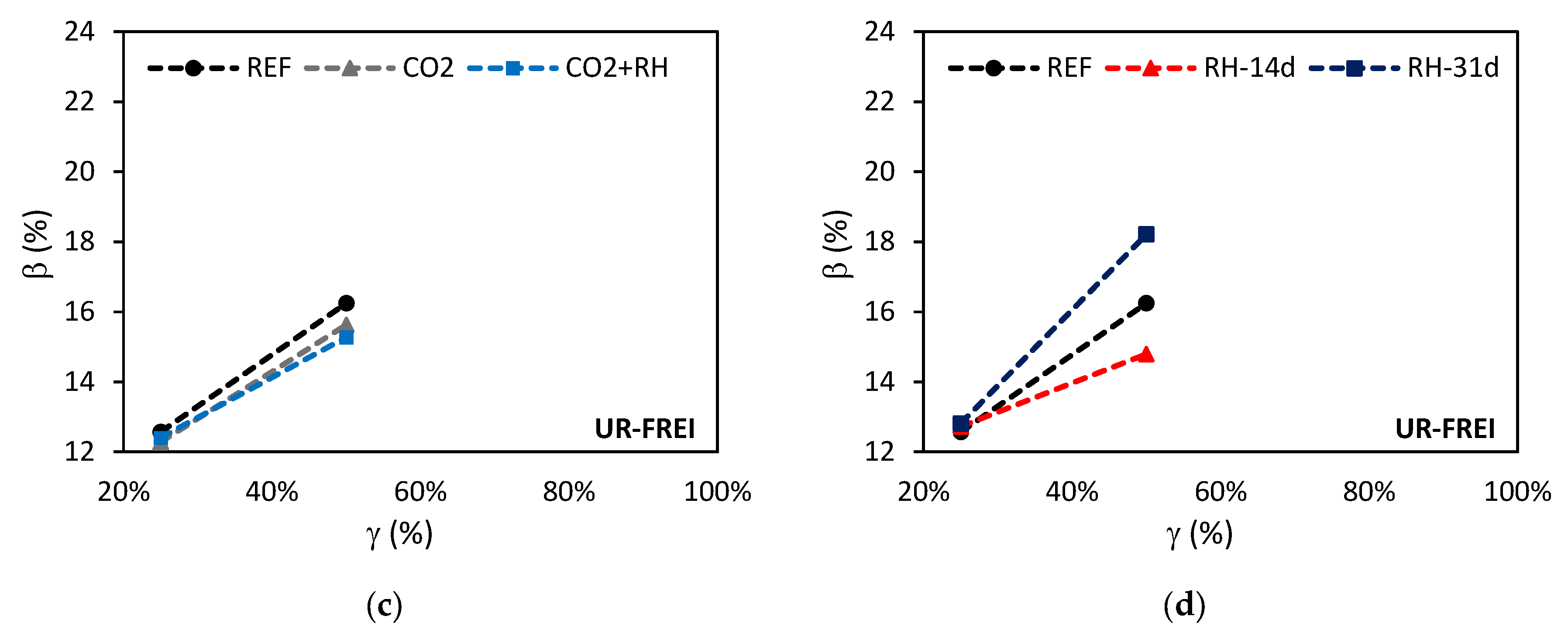
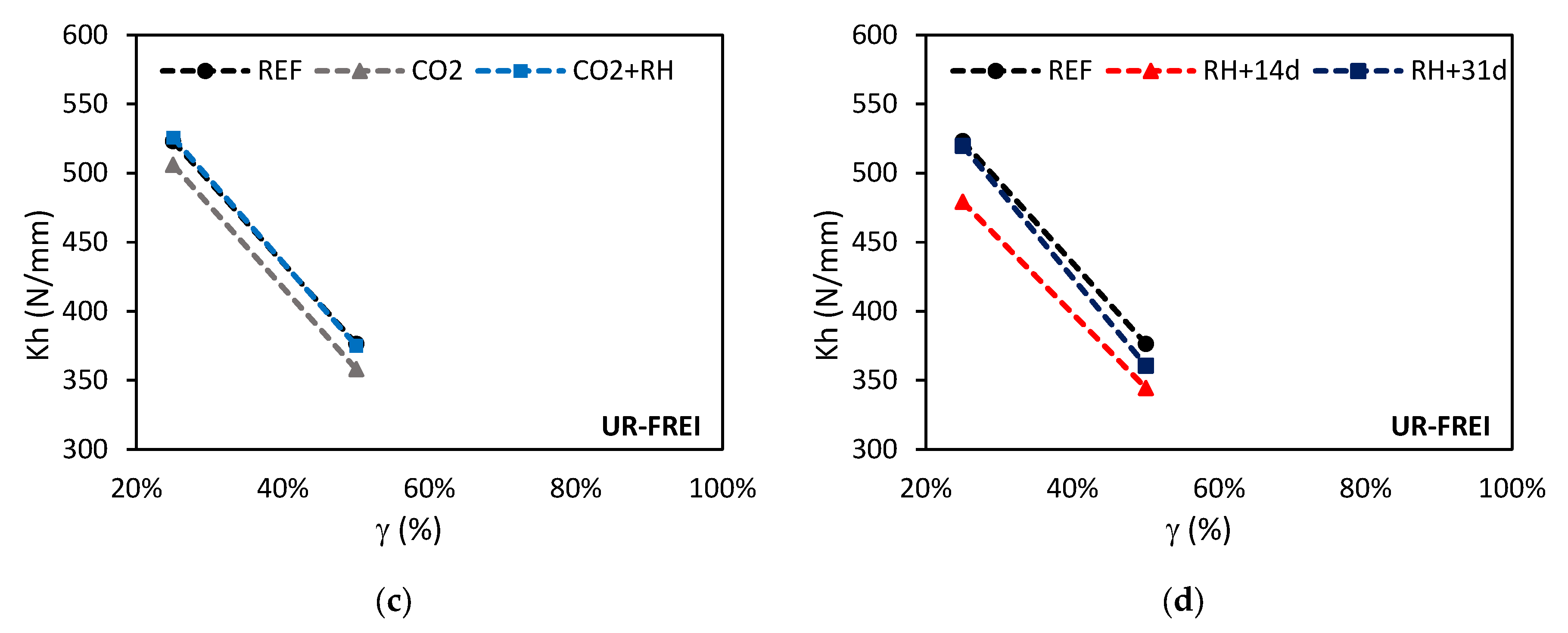
3.2.1. Shear Compression Test

The shear compression test was conducted on small-scale prototypes under two exposure conditions available at Pankow Materials Laboratories: (i) a 20% CO2 environment for 10 days, followed by an 85% RH environment for another 7 days. In each case, three prototypes of each material were tested. The nomenclature used was CO2 for the first phase and CO2+RH for the combined exposure. And (ii) a constant 85% RH environment. Three prototypes of each material were tested at 14 and 31 days. The nomenclature used was RH-14d and RH-31d, respectively. The loading protocol (Figure 6a) was also applied to reference prototypes, designated as REF. Figure 15 summarizes the results obtained for damping as a function of horizontal displacement and exposure type. For UR-FREI, the damping and stiffness values were limited to 50% deformation due to the lack of flexibility of the prototypes beyond that level.
In general, the damping of UN-FREI decreased as the shear strain increased up to 67%, but then increased when reaching 100% and 75% strain in both exposure conditions (Figure 15a,b). Regarding the effect of the environmental conditions evaluated, the greatest deviation from the reference value was observed with CO2 exposure, resulting in a damping loss of 3.43% and 3.63% at 67% and 75% deformation, respectively. In contrast, the combination of CO2+RH resulted in less than a 1% difference from the reference value (Figure 15a).
Exposure to constant RH led to an increase in damping at almost all strain levels in UN-FREI, with the greatest gain occurring after 31 days of exposure. At 67% and 75% strain, damping increased by 2.12% and 2.60%, respectively (Figure 15b).
Contrary to the behavior of UN-FREI, the damping value of UR-FREI increased with increasing strain levels in all evaluated cases. However, exposure to CO2 and CO2+RH led to a reduction in damping at 50% strain, with values 3.80% and 5.99% lower than the reference value, respectively (Figure 15c).
Exposure to constant RH initially caused a decrease in damping of 8.96% at 14 days, followed by an increase of 12.12% at 31 days at 50% strain. Although both materials exhibited higher damping at 31 days of constant RH exposure, a difference was observed at 14 days: while damping increased in UN-FREI, it decreased in UR-FREI (Figure 15d).
Figure 16 presents the results for horizontal stiffness as a function of horizontal displacement and each type of exposure.
The horizontal stiffness of UN-FREI decreased as the shear strain increased in both exposure conditions (Figure 16a,b). Among the evaluated environmental conditions, all resulted in an increase in stiffness compared to the reference value, except for RH at 14 days, which caused a slight stiffness reduction of 0.42% at 100% strain (Figure 16b). The greatest increase occurred after 31 days of RH exposure, with gains of 10.60% and 7.22% at 100% and 75% strain, respectively.
Similar to UN-FREI, the horizontal stiffness of UR-FREI also decreased as the strain level increased. However, in contrast to the reference value, stiffness decreased under all evaluated environmental conditions, except for the CO2+RH combination, which led to a slight increase of 0.50% at 25% strain (Figure 16c). Exposure to RH for 14 days resulted in a stiffness reduction of 8.40% and 8.49% at 25% and 50% strain, respectively.

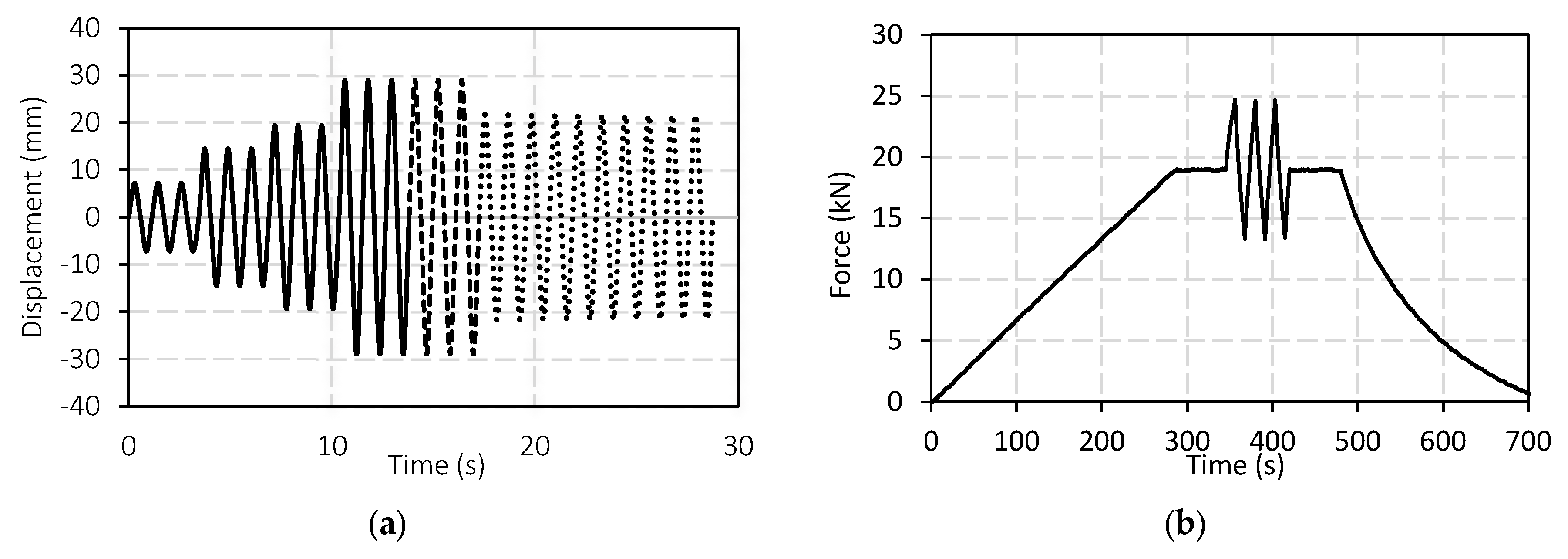
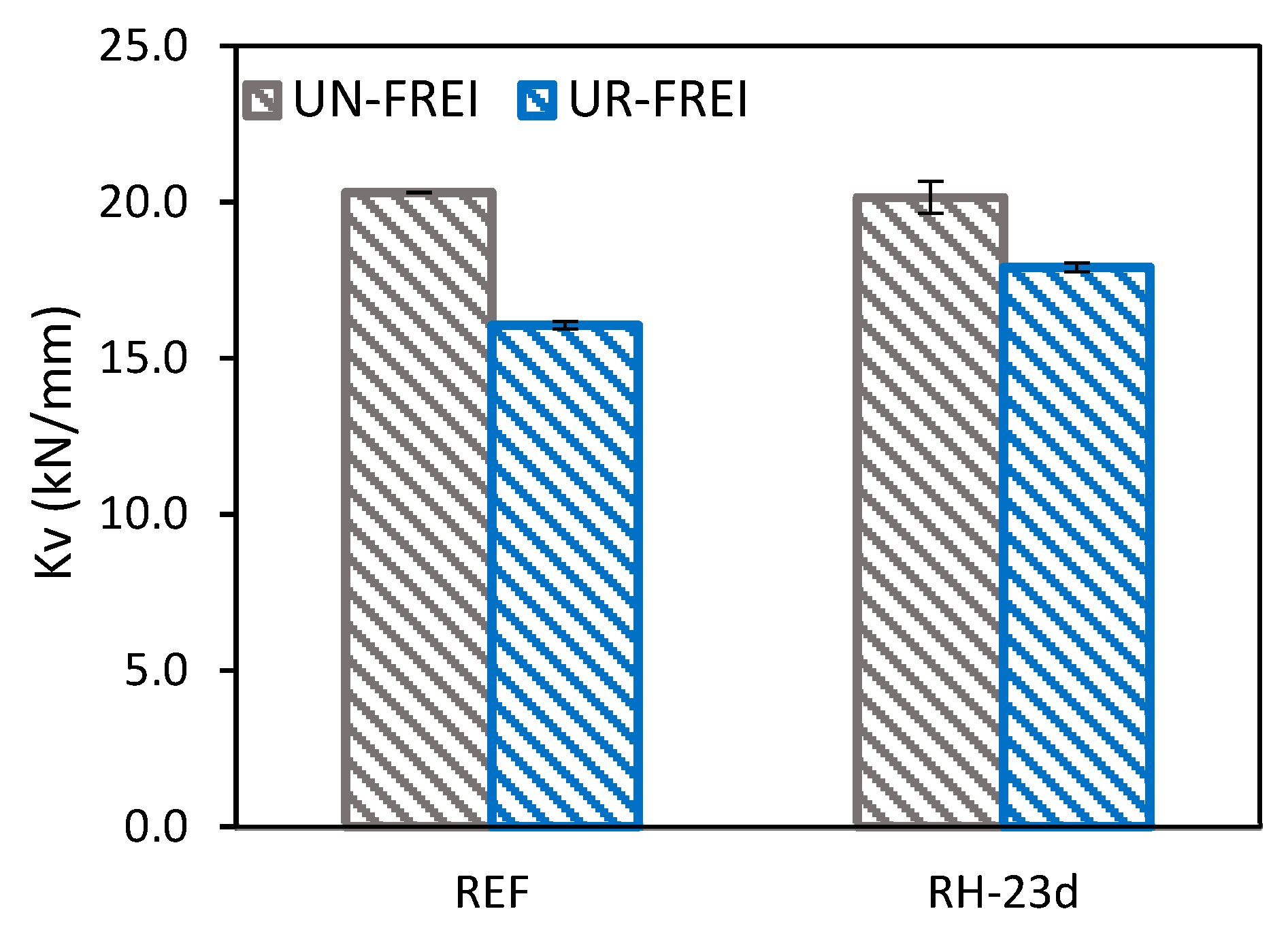
3.2.2. Cyclic Compression Test

The cyclic compression test was conducted on prototypes under 85% RH to complete the characterization of this environmental condition, which is common in Colombia. In each case, two prototypes were tested for each material. Since UR-FREI exhibited a tendency toward constant behavior after 20 days (as observed in Figure 8d,e), an exposure period of 23 days was selected. The nomenclature used for these specimens was RH-23d. The loading protocol (Figure 6b) was also applied to reference prototypes, designated as REF.
Figure 17 summarizes the vertical stiffness values obtained for the UN-FREI and UR-FREI small-scale prototypes. While 20.31 kN was required to deform the UN-FREI prototypes by 1 mm, only 16.06 kN was needed to achieve the same deformation in the UR-FREI prototypes (Figure 17). This difference is possibly due to the heterogeneous nature of the recycled rubber compound, which contains a greater number of pores in its structure, reducing the material’s compressive strength. Exposure to RH for 23 days resulted in a 0.79% reduction in vertical stiffness for UN-FREI, whereas UR-FREI exhibited an 11.50% increase in vertical stiffness under the same conditions.

3.2.3. Summary of Small-Scale Prototypes Results

The criteria in Table 3 were used to evaluate the results obtained from exposing the small-scale prototypes to the considered environmental conditions (Table 5).
In general, more properties fell within the slight range in the UN-FREI small-scale prototypes compared to the UR-FREI prototypes, indicating greater stability of the UN-FREI prototypes against environmental conditions.
Increased stiffness leads to higher accelerations due to a shorter period in the response spectrum of the isolated building, which should be avoided when designing a structure. Conversely, an increase in damping helps reduce displacements.
In the UN-FREI and UR-FREI specimens, the shear modulus (which is directly proportional to horizontal stiffness) and damping decreased after 30 days of RH exposure. However, in the UN-FREI small-scale prototypes, both horizontal stiffness and damping increased after 31 days of RH exposure, whereas in the UR-FREI small-scale prototypes, stiffness decreased while damping increased under the same conditions. No direct relationship can be established between the matrix results and the scaled prototypes. This behavior is similar to the findings in Section 3.1.1, where mass gain varied with specimen size.

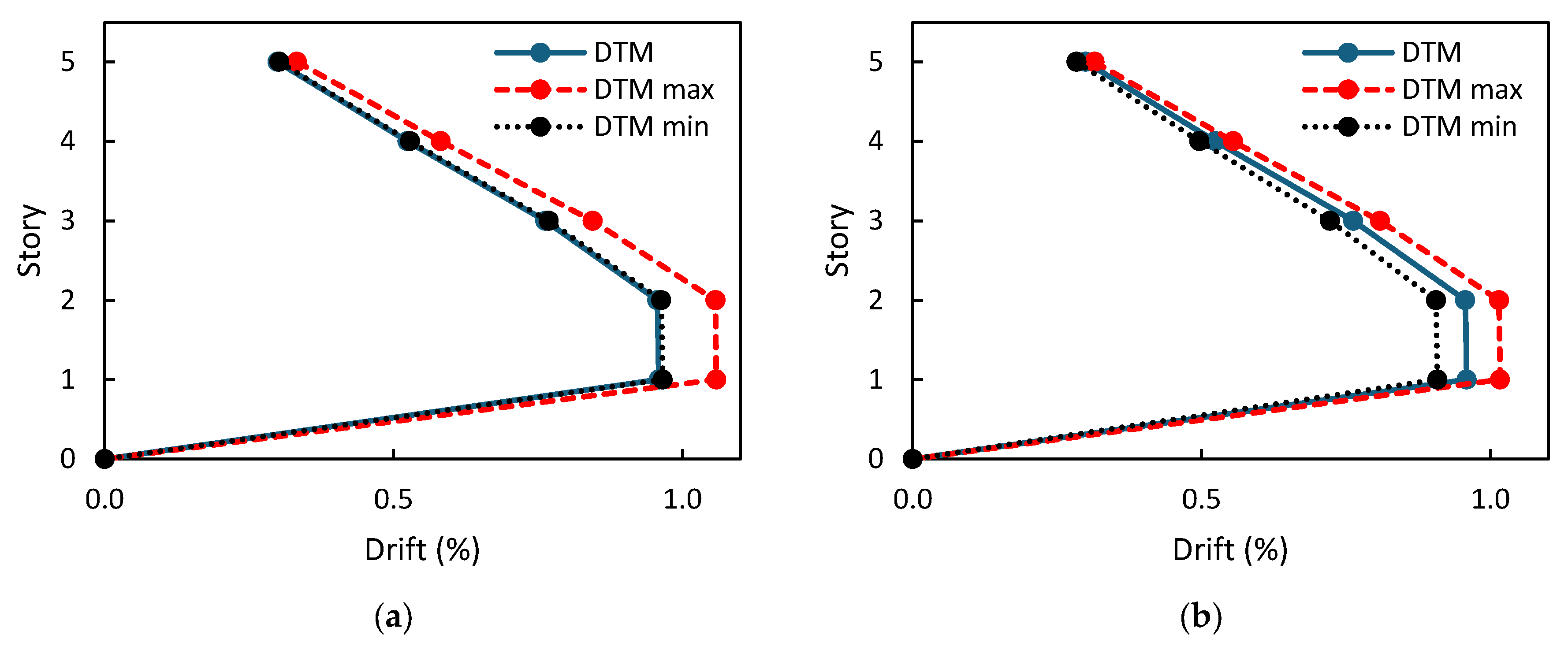
3.3. Evaluation of the Seismic Response of a Base-Isolated Structure

According to ASCE 7-16 [55], Chapter 17.2.8.4. Property Modification Factors, maximum and minimum modification factors (λ) should be applied to account for the variability of parameters due to temperature effects, aging, environmental exposure, and contamination. The maximum and minimum values are determined using Equatiton (3) and Equatiton (4), respectively.
λ m a x = ( 1 + 0.75     λ a e , m a x 1     λ t e s t ,   m a x     λ s p e c .   m a x 1.8
λ m i n = ( 1 0.75     1 λ a e , m i n     λ t e s t ,   m i n     λ s p e c .   m i n 0.6
λ a e ,   m a x , λ a e ,   m i n = property modification factors used to calculate the maximum and minimum property values of the isolator of interest, respectively, accounting for the effects of aging and environmental conditions.
λ t e s t ,   m a x , λ t e s t ,   m i n = property modification factors used to calculate the maximum and minimum property values of the isolator of interest, respectively, accounting for the effects of heating, loading rate, and scraping.
λ s p e c ,   m a x , λ s p e c ,   m i n = property modification factors used to calculate the maximum and minimum values of the isolator property of interest, respectively, accounting for variations in the manufacturing process. Additionally, ASCE 7-16 [55] provides default modification values when the manufacturer is unknown and isolator quality tests are not available (Table 6).
To analyze how seismic isolators exposed to environmental conditions could affect the seismic response of a building, the results of the mechanical tests were incorporated into the building model.
Initially, the maximum gain and loss of horizontal stiffness, vertical stiffness, and damping were calculated based on the type of exposure. Then, an average value of increase and reduction for each property was determined to establish λ(ae,max) and λ(ae,min). Equations (3) and (4) were modified to consider only the modification factor accounting for environmental conditions. That is, λ(test,max), λ(test,min), λ(spec,max), and λ(spec,min) were assumed to be 1, following the procedure used by Calabrese et al. [38]. Table 7 presents the factors used to modify the properties of fiber-reinforced isolators in the building model. The DTM model represents the case with no change in properties, while DTM max corresponds to the model using λ(ae,,max), and DTM min corresponds to the model using λ(ae,min).
When comparing Table 4 and Table 5, the values presented for λ(ae,max) and λ(ae,min) are lower than those proposed in ASCE 7-16 [55]. The modification factors defined by ASCE 7-16 [55] ensure that the properties used in analysis and design reflect unfavorable conditions and incorporate a safety margin by accounting for the potential degradation of the isolation system due to environmental exposure. According to Equations (3) and (4), these factors modify the properties of the isolators by more than 40%, which, in the most critical case, leads to higher drifts, shear forces, and demand-to-capacity ratio (DCR). DCR is the ratio of demand to capacity of a structural element and is less than 1. The values found in this research provide a more realistic approach to the factors that can be applied in the design of isolated structures based on laboratory tests performed on UN-FREI and UR-FREI materials.
Figure 18 shows the inter-story drifts for UN-FREI and UR-FREI, which represent the relative lateral displacement between two consecutive floors. This parameter is a relevant factor in evaluating the seismic response of buildings, as excessive drifts can lead to structural and non-structural damage. According to FEMA 450 [54], the allowable limit for isolated buildings analyzed using spectral methods is 1.5%. The drift for the isolated building without modification factors was close to 1.0% because, as the column dimensions continued to be reduced, the DCR was exceeded.
In the case of UN-FREI, λ(ae,min) for Kh, β, and Kv were close to 1, which explains why the drifts with DTM and DTM min are very similar. However, when applying the factor λ(ae,max), the drifts increased. For UR-FREI, it is observed that λ(ae,max) increases the drifts, while λ(ae,min) decreases them.
The fundamental period of a structure with seismic isolation at the base is largely determined by the horizontal stiffness of the isolated system and the total mass of the structure (Equation (5)). As Kh increases, the fundamental period of the isolated system decreases, leading to an increase in the stiffness of the structure. A shorter period in the response spectrum results in higher accelerations, which in turn increases the forces transmitted to the building and consequently the inter-story drifts.
T M = 2 π M K h
Table 8 presents the periods in the first mode of vibration obtained for DTM, DTM max, and DTM min in both materials.
The shear forces per story are shown in Figure 19. DTM and DTM min exhibit nearly identical shear forces per story because the modification factor is close to 1. When applying the factor λ(ae,max), the shear forces per story increased by 545 kN for UN-FREI and 373 kN for UR-FREI.
As Kh increases, the base shear also increases because the seismic forces transmitted to the base become greater.
Figure 20 shows the DCRs of two columns in the first story (Figure 7a). The forces should not exceed the structural element’s capacity, as indicated by the DCRs remaining below 1.0.
When λ(ae,max) is applied, the DCRs increase in the columns of the building with UN-FREI, meaning the element is working closer to its maximum capacity, which increases the risk of building failure. This behavior occurs because the period is shorter, leading to greater seismic forces that must be absorbed by the structural elements. Consequently, larger amounts of steel and increased column dimensions will be required to control drifts, which are also affected. In contrast, the internal forces are smaller when applying λ(ae,min). The DCRs for λ(ae,max) and λ(ae,min) are lower in UR-FREI because these isolators result in shorter periods than those of UN-FREI (Table 8).

4. Conclusions

This paper presents an investigation conducted to evaluate the effect of environmental conditions on a series of relevant mechanical properties of a natural rubber mixture (UN-FREI) and a recycled rubber compound (UR-FREI), materials that can be used to manufacture low-cost seismic isolators in Colombia. Comparisons were made between the two materials to determine differences in their behavior.
The size of the isolators plays a significant role in how environmental conditions affect their properties. The mechanical properties evaluated in UN-FREI and UR-FREI showed greater changes in the specimens than in the small-scale prototypes. Small samples have a higher surface-to-volume ratio, which facilitates greater interaction with the surrounding environment.
The maximum change observed for all properties and conditions evaluated was 41.6% for UN-FREI specimens and 48.6% for UR-FREI specimens under saltwater exposure. In contrast, the maximum change for small-scale prototypes was significantly lower, with 11.6% for UN-FREI and 12.1% for UR-FREI under RH-31d exposure. Small-scale prototypes have a larger volume relative to their surface area, reducing the influence of environmental conditions on their properties.
In the small-scale prototypes, horizontal stiffness increased in UN-FREI under the evaluated conditions, with the greatest gain occurring after 31 days of RH exposure, reaching 10.60% and 7.22% at 100% and 75% strain, respectively. The increase in stiffness may limit the ability of the devices to absorb and dissipate energy through the viscoelastic deformation of the elastomeric material. In other words, the damping capacity of the structural system may be reduced.
This effect must be carefully considered in UR-FREI, as these isolators already exhibit high horizontal stiffness and a maximum deformation of 50%. A system with high effective stiffness tends to have limited deformation capacity during a seismic event. This behavior implies that the dissipation system may reach its maximum deformation capacity more quickly, exposing the structure to direct seismic forces. Additionally, the high effective stiffness of UR-FREI made it difficult to observe significant changes under different environmental exposures.
The modification factors in ASCE 7-16 [55] establish a range of structural design safety against exposure conditions throughout the building’s lifespan. However, the environmental modification factors obtained in this study are lower than those defined in ASCE 7-16 [55], emphasizing the importance of manufacturers conducting tests to quantify the effects of aging, environmental conditions, heating, loading rate, and manufacturing variations. Performing such testing may justify the use of values different from the standard, which could be more conservative and lead to oversizing the isolators. It was observed that including the modification factors in the modeling of the isolated structure (λ(ae,max) y λ(ae,min)) affects the building’s response, particularly when applying the maximum factor. Drift, base shear, and DCRs increase due to the reduction in the period and the increase in accelerations, which may lead to a highly conservative structural design.
Finally, for future research, it is recommended to improve the recycled rubber mixture to enhance the cohesion of the particles and allow greater deformations in tensile tests for specimens and shear-compression tests for small-scale prototypes. Additionally, extending the exposure time to the environmental agents examined in this study could provide further insight into the material’s long-term behavior, ultimately enabling the establishment of property modification factors based on experimental results.

Author Contributions

Conceptualization, E.D.L.-M., I.C.V.-C., I.E.M.-S., M.A.R.-M., O.C., S.J.D. and M.V.-L.; Methodology, E.D.L.-M., I.C.V.-C., I.E.M.-S., M.A.R.-M., O.C., E.P., M.S.-B., M.L.-A., S.J.D. and M.V.-L.; Software, E.D.L.-M. and I.C.V.-C.; Validation, E.D.L.-M., I.C.V.-C., I.E.M.-S., M.A.R.-M., O.C. and M.V.-L.; Formal analysis, E.D.L.-M., I.C.V.-C., I.E.M.-S., M.A.R.-M., O.C., E.P., M.S.-B., M.L.-A., S.J.D. and M.V.-L.; Investigation, E.D.L.-M., I.C.V.-C., E.P., M.S.-B. and M.L.-A.; Resources, I.E.M.-S., M.A.R.-M., E.P., M.S.-B. and M.L.-A.; Data curation, E.D.L.-M. and I.C.V.-C.; Writing—original draft, E.D.L.-M., I.C.V.-C., I.E.M.-S., M.A.R.-M., E.P., M.S.-B., M.L.-A., S.J.D. and M.V.-L.; Writing—review & editing, E.D.L.-M., I.E.M.-S., M.A.R.-M., O.C., E.P., M.S.-B., M.L.-A., S.J.D. and M.V.-L.; Visualization, E.D.L.-M., I.C.V.-C., I.E.M.-S., M.A.R.-M., O.C., E.P., M.S.-B., M.L.-A., S.J.D. and M.V.-L.; Supervision, E.D.L.-M., I.E.M.-S., M.A.R.-M., O.C., S.J.D. and M.V.-L.; Project administration, I.E.M.-S. and M.A.R.-M.; Funding acquisition, I.E.M.-S., M.A.R.-M. and O.C. All authors have read and agreed to the published version of the manuscript.

Funding

This research was funded by the Internal Grant “Por una Universidad Transformadora: Horizonte 2021-2025” (20100776) of the Pontificia Universidad Javeriana Cali (PUJC). The entity that financed the project did not participate in the decision-making process related to the experimental process, or to the publication process of this article.

Institutional Review Board Statement

Not applicable.

Informed Consent Statement

Not applicable.

Data Availability Statement

The original contributions presented in this study are included in the article. Further inquiries can be directed to the corresponding author.

Acknowledgments

The authors acknowledge the Fulbright Colombia Scholar Program, as well as the distinguished professors and students at Purdue University and Pontificia Universidad Javeriana in Cali and Bogotá, and MATCON research group, for their valuable support during the experimental phase of this study. We would also like to thank the companies Surtidor Industrial S.A.S. and Occidental de Cauchos S.A.S. for their valuable support in this research.

Conflicts of Interest

The authors declare no conflict of interest.

References

  1. Madera Sierra, I.E.; Losanno, D.; Strano, S.; Marulanda, J.; Thomson, P. Development and experimental behavior of HDR seismic isolators for low-rise residential buildings. Eng. Struct. 2019, 183, 894–906. [Google Scholar] [CrossRef]
  2. Thenozhi, S.; Yu, W. Advances in modeling and vibration control of building structures. Annu. Rev. Control 2013, 37, 346–364. [Google Scholar] [CrossRef]
  3. Zhang, C.; Ali, A. The advancement of seismic isolation and energy dissipation mechanisms based on friction. Soil Dyn. Earthq. Eng. 2021, 146, 106746. [Google Scholar] [CrossRef]
  4. De Domenico, D.; Longo, P.; Losanno, D.; Maugeri, N.; Ricciardi, G.; Vaiana, N. Full-scale experimental tests on unbonded fiber reinforced elastomeric isolators under bidirectional excitation. Procedia Struct. Integr. 2023, 44, 1498–1505. [Google Scholar] [CrossRef]
  5. Foti, D. Response of frames seismically protected with passive systems in near-field areas. Int. J. Struct. Eng. 2014, 5, 326–345. [Google Scholar] [CrossRef]
  6. Losanno, D.; De Domenico, D.; Madera-Sierra, I.E. Experimental testing of full-scale fiber reinforced elastomeric isolators (FREIs) in unbounded configuration. Eng. Struct. 2022, 260, 114234. [Google Scholar] [CrossRef]
  7. Losanno, D.; Madera Sierra, I.E.; Spizzuoco, M.; Marulanda, J.; Thomson, P. Experimental assessment and analytical modeling of novel fiber-reinforced isolators in unbounded configuration. Compos. Struct. 2019, 212, 66–82. [Google Scholar] [CrossRef]
  8. Losanno, D.; Madera Sierra, I.E.; Spizzuoco, M.; Marulanda, J.; Thomson, P. Experimental performance of unbonded polyester and carbon fiber reinforced elastomeric isolators under bidirectional seismic excitation. Eng. Struct. 2020, 209, 110003. [Google Scholar] [CrossRef]
  9. Stanikzai, M.H.; Elias, S.; Matsagar, V.A.; Jain, A.K. Seismic response control of base-isolated buildings using multiple tuned mass dampers. Struct. Des. Tall Spec. Build. 2019, 28, e1576. [Google Scholar] [CrossRef]
  10. Stanikzai, M.H.; Elias, S.; Matsagar, V.A.; Jain, A.K. Seismic response control of base-isolated buildings using tuned mass damper. Aust. J. Struct. Eng. 2020, 21, 310–321. [Google Scholar] [CrossRef]
  11. Toopchi-Nezhad, H.; Tait, M.J.; Drysdale, R.G. Bonded versus unbonded strip fiber reinforced elastomeric isolators: Finite element analysis. Compos. Struct. 2011, 93, 850–859. [Google Scholar] [CrossRef]
  12. Van Engelen, N.C. Fiber-reinforced elastomeric isolators: A review. Soil Dyn. Earthq. Eng. 2019, 125, 105621. [Google Scholar] [CrossRef]
  13. Habieb, A.B.; Valente, M.; Milani, G. Base seismic isolation of a historical masonry church using fiber reinforced elastomeric isolators. Soil Dyn. Earthq. Eng. 2019, 120, 127–145. [Google Scholar] [CrossRef]
  14. Habieb, A.B.; Valente, M.; Milani, G. Implementation of a simple novel Abaqus user element to predict the behavior of unbonded fiber reinforced elastomeric isolators in macro-scale computations. Bull. Earthq. Eng. 2019, 17, 2741–2766. [Google Scholar] [CrossRef]
  15. Madera-Sierra, I.E. Desarrollo Tecnológico de un Aislador Sísmico de Bajo Costo Para Edificaciones Bajas [Technological Development of a Low-Cost Seismic Isolator for Low-Rise Buildings]. Ph.D. Thesis, Universidad del Valle, Cali, Colombia, 2018. [Google Scholar]
  16. Ortega Escobar, L.F. Prototipos de Aisladores Sísmicos Con Matriz de Caucho Reciclado Para la Mitigación de Riesgo en Estructuras [Prototypes of Seismic Isolators with Recycled Rubber Matrix for Risk Mitigation in Structures]. Master’s Thesis, Universidad del Valle, Cali, Colombia, 2021. [Google Scholar]
  17. De Domenico, D.; Losanno, D.; Vaiana, N. Experimental tests and numerical modeling of full-scale unbonded fiber reinforced elastomeric isolators (UFREIs) under bidirectional excitation. Eng. Struct. 2023, 274, 115118. [Google Scholar] [CrossRef]
  18. Nilsson, L.-O. Corrosion of steel in concrete. In Developments in the Formulation and Reinforcement of Concrete; Elsevier: Amsterdam, The Netherlands, 2019; pp. 115–129. [Google Scholar] [CrossRef]
  19. Xu, Z.; Zhang, Z.; Huang, J.; Yu, K.; Zhong, G.; Chen, F.; Chen, X.; Yang, W.; Wang, Y. Effects of temperature, humidity and CO2 concentration on carbonation of cement-based materials: A review. Constr. Build. Mater. 2022, 346, 128399. [Google Scholar] [CrossRef]
  20. Alyami, M.H.; Alrashidi, R.S.; Mosavi, H.; Almarshoud, M.A.; Riding, K.A. Potential accelerated test methods for physical sulfate attack on concrete. Constr. Build. Mater. 2019, 229, 116920. [Google Scholar] [CrossRef]
  21. Qu, F.; Li, W.; Dong, W.; Tam, V.W.Y.; Yu, T. Durability deterioration of concrete under marine environment from material to structure: A critical review. J. Build. Eng. 2021, 35, 102074. [Google Scholar] [CrossRef]
  22. Tansel, B.; Zhang, K. Effects of saltwater intrusion and sea level rise on aging and corrosion rates of iron pipes in water distribution and wastewater collection systems in coastal areas. J. Environ. Manag. 2022, 315, 115153. [Google Scholar] [CrossRef]
  23. Boubakri, A.; Guermazi, N.; Elleuch, K.; Ayedi, H.F. Study of UV-aging of thermoplastic polyurethane material. Mater. Sci. Eng. A 2010, 527, 1649–1654. [Google Scholar] [CrossRef]
  24. Diepens, M.; Gijsman, P. Photo-oxidative degradation of bisphenol A polycarbonate and its possible initiation processes. Polym. Degrad. Stab. 2008, 93, 1383–1388. [Google Scholar] [CrossRef]
  25. Xie, F.; Zhang, T.; Bryant, P.; Kurusingal, V.; Colwell, J.M.; Laycock, B. Degradation and stabilization of polyurethane elastomers. Prog. Polym. Sci. 2019, 90, 211–268. [Google Scholar] [CrossRef]
  26. Gu, H.; Itoh, Y.; Satoh, K. Effect of rubber bearing ageing on seismic response of base-isolated steel bridges. In Proceedings of the Fourth International Conference on Advances in Steel Structures, Shanghai, China, 13–15 June 2005; Elsevier: Amsterdam, The Netherlands, 2005; pp. 1627–1632. [Google Scholar] [CrossRef]
  27. Gu, H.S.; Itoh, Y. Ageing Behaviour of Natural Rubber and High Damping Rubber Materials Used in Bridge Rubber Bearings. Adv. Struct. Eng. 2010, 13, 1105–1113. [Google Scholar] [CrossRef]
  28. Matsuzaki, H. Time-dependent seismic reliability of isolated bridges considering ageing deterioration of lead rubber bearings. Struct. Infrastruct. Eng. 2022, 18, 1526–1541. [Google Scholar] [CrossRef]
  29. ASTM D573-04; Standard Test Method for Rubber—Deterioration in an Air Oven. Volume 4, Issue Reapproved; ASTM International: West Conshohocken, PA, USA, 2019; pp. 1–6. [CrossRef]
  30. Itoh, Y.; Gu, H.S. Prediction of Aging Characteristics in Natural Rubber Bearings Used in Bridges. J. Bridge Eng. 2009, 14, 122–128. [Google Scholar]
  31. Wang, M.; Zhang, G. Mechanical properties and seismic isolation behavior of scrap tire pads subjected to thermal-cold cycles in rural construction. Structures 2022, 40, 607–620. [Google Scholar] [CrossRef]
  32. Calabrese, A.; Spizzuoco, M.; Serino, G.; Della Corte, G.; Maddaloni, G. Shaking table investigation of a novel, low-cost, base isolation technology using recycled rubber. Struct. Control. Health Monit. 2015, 22, 107–122. [Google Scholar] [CrossRef]
  33. Spizzuoco, M.; Calabrese, A.; Serino, G. Innovative low-cost recycled rubber–fiber reinforced isolator: Experimental tests and Finite Element Analyses. Eng. Struct. 2014, 76, 99–111. [Google Scholar] [CrossRef]
  34. Habieb, A.B.; Milani, F.; Milani, G.; Cerchiaro, R. Rubber compounds made of reactivated EPDM for fiber-reinforced elastomeric isolators: An experimental study. Iran. Polym. J. 2020, 29, 1031–1043. [Google Scholar] [CrossRef]
  35. Habieb, A.B.; Milani, G.; Cerchiaro, R.; Quaglini, V.; Milani, F. Numerical study on rubber compounds made of reactivated ethylene propylene diene monomer for fiber reinforced elastomeric isolators. Polym. Eng. Sci. 2021, 61, 258–277. [Google Scholar] [CrossRef]
  36. Losanno, D.; Palumbo, F.; Calabrese, A.; Barrasso, T.; Vaiana, N. Preliminary Investigation of Aging Effects on Recycled Rubber Fiber Reinforced Bearings (RR-FRBs). J. Earthq. Eng. 2022, 26, 5407–5424. [Google Scholar] [CrossRef]
  37. Ragni, L.; Micozzi, F.; Gioiella, L.; Castellano, M.G.; Infanti, S.; Dall’Asta, A. λ-Factors for the Upper and Lower Bound Analyses of Base-Isolated Structures: Historical Review of Code Provisions for Elastomeric Bearings. Appl. Sci. 2023, 13, 5820. [Google Scholar] [CrossRef]
  38. Calabrese, A.; Losanno, D.; Barjani, A.; Spizzuoco, M.; Strano, S. Effects of the long-term aging of glass-fiber reinforced bearings (FRBs) on the seismic response of a base-isolated residential building. Eng. Struct. 2020, 221, 110735. [Google Scholar] [CrossRef]
  39. Ortega, L.F.; Herazo, M.Z.; Ortiz, A.R.; Thomson, P.; Marulanda, J. Performance of prototype seismic isolators reinforced with fiber and a recycled rubber tire matrix. Eng. Struct. 2023, 278, 115422. [Google Scholar] [CrossRef]
  40. Heikkilä, A.; Kärhä, P.; Tanskanen, A.; Kaunismaa, M.; Koskela, T.; Kaurola, J.; Ture, T.; Syrjälä, S. Characterizing a UV chamber with mercury lamps for assessment of comparability to natural UV conditions. Polym. Test. 2009, 28, 57–65. [Google Scholar] [CrossRef]
  41. Cambier, S.M.; Frankel, G.S. Coating and Interface Degradation of Coated steel, Part 2: Accelerated Laboratory Tests. Electrochim. Acta 2014, 136, 442–449. [Google Scholar] [CrossRef]
  42. Shimizu, K.; Tokuta, Y.; Oishi, A.; Kuriyama, T.; Kunioka, M. Weatherability of Polypropylene by Accelerated Weathering Tests and Outdoor Exposure Tests in Japan. J. Polym. 2016, 2016, 6539567. [Google Scholar] [CrossRef]
  43. Le Gac, P.Y.; Le Saux, V.; Paris, M.; Marco, Y. Ageing mechanism and mechanical degradation behaviour of polychloroprene rubber in a marine environment: Comparison of accelerated ageing and long term exposure. Polym. Degrad. Stab. 2012, 97, 288–296. [Google Scholar] [CrossRef]
  44. Auroy, M.; Poyet, S.; Le Bescop, P.; Torrenti, J.M.; Charpentier, T.; Moskura, M.; Bourbon, X. Comparison between natural and accelerated carbonation (3% CO2): Impact on mineralogy, microstructure, water retention and cracking. Cem. Concr. Res. 2018, 109, 64–80. [Google Scholar] [CrossRef]
  45. Liu, M.; Ju, X.; Wu, L.; Guo, Q.; Wang, H.; Zhang, W. Carbonation depth model for loaded reinforced concrete (RC) beams under time-dependent relative humidity conditions. J. Build. Eng. 2023, 65, 105618. [Google Scholar] [CrossRef]
  46. Shah, V.; Bishnoi, S. Carbonation resistance of cements containing supplementary cementitious materials and its relation to various parameters of concrete. Constr. Build. Mater. 2018, 178, 219–232. [Google Scholar] [CrossRef]
  47. Van den Heede, P.; Thiel, C.; De Belie, N. Natural and accelerated carbonation behaviour of high-volume fly ash (HVFA) mortar: Effects on internal moisture, microstructure and carbonated phase proportioning. Cem. Concr. Compos. 2020, 113, 103713. [Google Scholar] [CrossRef]
  48. ASTM D412-16; Standard Test Methods for Vulcanized Rubber and Thermoplastic Elastomers—Tension. ASTM International: West Conshohocken, PA, USA, 2021; pp. 1–14. [CrossRef]
  49. ASTM D575-91; Standard Test Methods for Rubber Properties in Compression. ASTM International: West Conshohocken, PA, USA, 2018; pp. 1–4. [CrossRef]
  50. ASTM D395-18; Standard Test Methods for Rubber Property—Residual compression. ASTM International: West Conshohocken, PA, USA, 2018; pp. 1–8. [CrossRef]
  51. ATC-17; ATC-17-2 Seminar on Response Modification Performance-Based Seismic Design. A.T.C.: Carson, CA, USA, 2002.
  52. ASTM D4014-03; Standard Specification for Plain and Steel-Laminated Elastomeric Bearings for Bridges. ASTM International: West Conshohocken, PA, USA, 2018; pp. 1–7. [CrossRef]
  53. AIS. Reglamento Colombiano de Construcción Sismo Resistente, NSR 10; Asociación Colombiana de Ingeniería Sísmica (AIS): Bogotá, Colombia, 2010. [Google Scholar]
  54. FEMA 450. Recommended Provisions for Seismic Regulations for New Buildings and Other Structures (FEMA 450); Building Seismic Safety Council (BSSC) of the National Institute of Building Sciences: Washington, DC, USA, 2003. [Google Scholar]
  55. ASCE. Minimum Design Loads and Associated Criteria for Buildings and Other Structures; American Society of Civil Engineers: Reston, VA, USA, 2017. [Google Scholar] [CrossRef]
  56. Pickett, J.E.; Coyle, D.J. Hydrolysis kinetics of condensation polymers under humidity aging conditions. Polym. Degrad. Stab. 2013, 98, 1311–1320. [Google Scholar] [CrossRef]
  57. Itoh, Y.; Gu, H.S. Effect of ultraviolet irradiation on surface rubber used in bridge bearing. J. Struct. Eng. 2007, 53A, 696–705. [Google Scholar] [CrossRef]
  58. Ma, Y.; Li, Y.; Zhao, G.; Zhou, F. Experimental research on the time-varying law of performance for natural rubber laminated bearings subjected to seawater dry-wet cycles. Eng. Struct. 2019, 195, 159–171. [Google Scholar] [CrossRef]
  59. Barmo, A.; Mualla, I.H.; Hasan, H.T. The Behavior of Multi-Story Buildings Seismically Isolated System Hybrid Isolation (Friction, Rubber and with the Addition of Rotational Friction Dampers). Open J. Earthq. Res. 2015, 4, 52406. [Google Scholar] [CrossRef]
Figure 1. Exposure to environmental conditions: (a) RH, (b) UV radiation, (c) drying-salt saltwater, and (d) CO2.
Applsci 15 03467 g001
Figure 2. Specimens for: (a) tension, (b) monotonic compression, and (c) residual compression tests.
Applsci 15 03467 g002
Figure 3. Specimens for cyclic shear test: (a) UN-FREI, and (b) UR-FREI.
Applsci 15 03467 g003
Figure 4. Dimensions of the UN-FREI and UR-FREI small-scale prototypes [7].
Applsci 15 03467 g004
Figure 5. Prototype tests: (a) shear compression test, and (b) cyclic compression test.
Applsci 15 03467 g005
Figure 6. Loading protocols: (a) shear compression test, and (b) cyclic compression test.
Applsci 15 03467 g006
Figure 7. Characteristics of the analyzed type of structure, (a) 3D and (b) the pseudo-acceleration spectra of the ground motion for a damping coefficient of 5%.
Applsci 15 03467 g007
Figure 8. Curves of mass gained over time according to the type of specimen: (a) tension, (b) monotonic compression, (c) residual compression, (d) shear compression prototypes, and (e) cyclic compression prototypes.
Applsci 15 03467 g008
Figure 9. RH exposure results for: (a) tension, (b) monotonic compression, and (c) residual compression (CB) tests.
Applsci 15 03467 g009
Figure 10. RH exposure results for the cyclic shear test: (a) shear modulus (G), and (b) damping ratio (β).
Applsci 15 03467 g010
Figure 11. UV radiation results for: (a) tension, (b) monotonic compression, and (c) residual compression (CB) tests.
Applsci 15 03467 g011
Figure 12. UV radiation results for the cyclic shear test: (a) shear modulus (G), and (b) damping ratio (β).
Applsci 15 03467 g012
Figure 13. Saltwater exposure results for: (a) tension, (b) monotonic compression, and (c) residual compression (CB) tests.
Applsci 15 03467 g013
Figure 14. Saltwater exposure results for the cyclic shear test: (a) shear modulus (G), and (b) damping ratio (β).
Applsci 15 03467 g014
Figure 15. Damping (β) vs. shear deformation (γ): (a) CO2+RH UN-FREI, (b) constant RH UN-FREI, (c) CO2+RH UR-FREI, and (d) constant RH UR-FREI.
Applsci 15 03467 g015aApplsci 15 03467 g015b
Figure 16. Horizontal stiffness (kh) vs. shear deformation (γ): (a) CO2+RH UN-FREI, (b) constant RH UN-FREI, (c) CO2+RH UR-FREI, and (d) constant RH UR-FREI.
Applsci 15 03467 g016aApplsci 15 03467 g016b
Figure 17. Vertical stiffness (Kv) of UN-FREI and UR-FREI after 23 days of exposure to RH.
Applsci 15 03467 g017
Figure 18. Comparison of drifts between DTM, DTM max, and DTM min: (a) UN-FREI, and (b) UR-FREI.
Applsci 15 03467 g018
Figure 19. Comparison of shear per story between DTM, DTM max, and DTM min: (a) UN-FREI, and (b) UR-FREI.
Applsci 15 03467 g019
Figure 20. Comparison of the demand-to-capacity ratio (DCR) between DTM, DTM max, and DTM min: (a) UN-FREI, and (b) UR-FREI.
Applsci 15 03467 g020
Table 1. Typical characteristics of the type structure analyzed.
ParameterValue
Concrete (MPa) (f’c)24
Steel (MPa) (fy)420
Columns45 × 45 cm
Beams35 × 40 cm, 40 × 50 cm
Number of stories5
Story height (m)3
Number of isolators20
Dead load (kN/m2)5.0
Live load (kN/m2)1.8
Weight of structure (kN)19,760
Design period2.5 s
Horizontal damping (γ = 160%)6.10%
Table 2. Characteristics and properties of isolators.
PropertySymbolValue
Thickness of rubber layers (mm)tr9.0
Number of layersn24
Polyester fiber thickness (mm)tf1.1
Total thickness of rubber (mm)Hr216.0
Total thickness of isolator (mm)H241.3
Isolator diameter (mm)D750
Total maximum displacement (m)DTM0.345
Period isolated structure (s)TM2.42
Fiber density (kg/m3)γfibra1000
Rubber density (kg/m3)γcaucho1200
Isolator mass (kg)Miso125
Isolator weight (N)Wiso1233
Vertical displacement characteristics U1
Effective stiffness (N/m)Kv146,303,417.64
Effective damping (N⋅s/m)Cv76,525.09
Horizontal displacement characteristics U2 = U3
Effective stiffness (N/m)Keff850,121.57
Effective damping (N⋅s/m)Ch41,266.82
Elastic stiffness (N/m)Ke2,151,572.72
Yield stress (N)fy46,473.97
Post-yield stiffness ratioKp/Ke0.35
Table 3. Evaluation criteria.
Range (%)State* Increase* Decrease
05Slight~↑~↓
510Moderate
1020Severe↑↑↓↓
2050Critical↑↑↑↓↓↓
* ↑/↓ indicate a moderate increase or decrease, ↑↑/↓↓ indicate a severe increase or decrease, ↑↑↑/↓↓↓ indicate a critical increase or decrease, ~ indicates a negligible change.
Table 4. Evaluation of the test results of UN-FREI and UR-FREI specimens.
UN-FREIUR-FREI
* ExposureTCR.C.GβTCR.C.Gβ
RH↓↓↓↓↑↑↑↓↓↓~↓~↓↓↓↑↑~↓↓↓
UV↑↑↑↓↓↓↓↓↓↑↑↑↑↑↓↓↓~↓
SW↑↑↑↓↓↓↑↑↑↑↑↓↓↓↓↓↓↓↓↑↑↑~↑↓↓
* T—tension, C—monotonic compression, R.C.—residual compression, G—shear modulus, β—damping ratio.
Table 5. Evaluation of the test results of UN-FREI and UR-FREI small-scale prototypes.
UN-FREIUR-FREI
* ExposureKhβCKhβC
CO2~↓ ~↓~↓
CO2+RH~↓ ~↑
RH-14d~↑~↑
RH-31d↑↑~↑ ~↓↑↑
RH-23d ~↓ ↑↑
* Kh—horizontal stiffness, β—damping ratio, C—cyclic compression.
Table 6. Default upper and lower limits for unknown manufacturers (Source: Table C17.2-6 (ASCE 7-16 [55]).
Maximum ValuesMinimum Values
Factor for aging effects and environmental conditions λ a e ,   m a x = 1.4 λ a e ,   m i n = 1.0
Factor for heating, rate of loading, and scragging. λ t e s t ,   m a x = 1.5 λ t e s t ,   m i n = 0.9
Factor or permissible manufacturing variation λ s p e c ,   m a x = 1.15 λ λ s p e c ,   m i n = 0.85
Table 7. Factors modifying environmental conditions.
UN-FREIUR-FREI
λ(ae,max) λ(ae,min)λ(ae,max) λ(ae,min)
Kh1.07Kh1.00Kh1.00Kh0.94
β1.03β0.98β1.12β0.94
Kv1.00Kv0.99Kv1.11Kv1.00
Table 8. Periods according to modification factors.
PeriodUN-FREIUR-FREI
T DTM (s)2.422.42
T DTM min (s)2.432.50
T DTM max (s)2.342.39
Disclaimer/Publisher’s Note: The statements, opinions and data contained in all publications are solely those of the individual author(s) and contributor(s) and not of MDPI and/or the editor(s). MDPI and/or the editor(s) disclaim responsibility for any injury to people or property resulting from any ideas, methods, instructions or products referred to in the content.

