Article

Methodology and Experimental Investigation of Linear Creep Behavior in Two-Layer Reinforced Concrete Beams

1
Department of Civil Engineering, Ariel University, Ariel 40700, Israel
2
Structural Concrete Institute, Leipzig University of Applied Sciences, 04275 Leipzig, Germany
*
Author to whom correspondence should be addressed.
Appl. Sci. 2025, 15(7), 3456; https://doi.org/10.3390/app15073456
Submission received: 17 February 2025 / Revised: 13 March 2025 / Accepted: 17 March 2025 / Published: 21 March 2025
(This article belongs to the Section Civil Engineering)

Abstract

:
This paper presents the first stage of an experimental investigation of creep in two-layer reinforced concrete beams. It deals with the methodology of testing beams under long-term loading aimed at the investigation of the real linear creep effect. The investigated beams consisted of a normal-strength concrete (NSC) in the tensile zone and steel-fibered high-strength concrete (SFHSC) in the compression one. The specimens are subjected to four-point bending under loads that correspond to 70 and 85% of their load-bearing capacity. The loads are applied using special amplifying devices. The experiments at this stage lasted 90 days. Deflections are measured in the midspan of each specimen. During the first 24 h after applying the loads, the deflections were recorded every 10 s, and after 24 h, every hour. During the tests, no cracks have been observed near the supports as well as between the NSC and SFHSC layers. The cracks appeared within the limits of the pure bending zone only. Load-deflection curves were obtained and analyzed. The maximum midspan deflection in the tested beams was less than 1/250 of the beam span, which indicated that at linear creep, the two-layer beams are safe and remain in the elastic stage. The obtained results form a basis for the second stage of the experimental research that will be focused on the non-linear creep effect in such beams.

1. Introduction

Concrete is the most popular construction material in the world, but its known disadvantages are low tensile strength, brittleness, and limited crack resistance [1]. Many experimental studies demonstrate that adding steel fibers can improve the mechanical properties of concrete [2,3]. Steel, basalt, polypropylene, glass, and other types of fibers are used in the concrete industry [4]. The addition of fibers improves the concrete properties and makes its use in modern construction more effective.
As is known, creep and shrinkage are two properties that increase the deformations in reinforced concrete (RC) structures under long-term loads [5]. Even without considering the effects of fibers, the mechanical behavior of reinforced concrete (RC) structures is complex due to effects such as shrinkage, creep, and cracking [6].
Additional deformations in RC structures during the lifetime period (commonly 50 years) due to creep are about three times higher than the elastic ones. Therefore, the concrete creep problem is one of the important aspects that are given special attention in modern codes [7,8,9,10,11] for the design of RC structures at the serviceability limit state (SLS).
Experimental results on the creep of high-strength concrete (70 MPa) and normal-strength concrete (40 MPa) were presented [12]. It was reported that creep strains of high-strength concrete are smaller than those of normal-strength concrete at all stress–strength ratios. The relation of creep to stress–strength ratio was found to be linear for the two grades of concrete.
A theoretical method to derive the concrete creep from the compressive creep test results was developed [13]. Three types of high-strength concrete were cast for the creep tests. The results demonstrated that concrete creep without considering the stress relaxation effect decreases by 4.3∼11.0% when 6.7∼13.1% of the applied stresses relax during the creep tests.
A software based on finite element methods was adopted to test available creep models [14]. A comparison of numerical and experimental results has shown that the algorithm can be used to model the creep of high-strength concrete if the material properties are previously experimentally assessed.
Although wide research on concrete creep was carried out during the last century, design codes still include experimentally based empirical coefficients. Definitions of elastic and plastic potentials of a system were given for linear and non-linear creeps [15]. It was concluded that concrete creep deformations are one of the indicators for RC structures’ repairing efficiency and/or necessity.
The long-term deflections predicted by the creep models in different design codes have a big difference [16]. Experimental results of creep strains in the high-strength concrete Sutong Bridge were compared with those obtained according to ACI 209 and other models [17]. A creep analysis method was proposed, and parameters in the fib MC 2010 creep model were calibrated according to a long-term loading experimental investigation of a prestressed concrete beam [18]. It was reported that the numerical results are in good agreement with the experimental ones.
An experimental study was carried out to investigate the creep deformations of fiber-reinforced concrete (FRC) beams under loading level Ps/P0 higher than 80% (Ps and P0 are the loads at reloading and before unloading, respectively) [19]. The beams’ deflection, crack width, and propagation were measured and analyzed. It was concluded that the obtained results form a basis for modeling creep with respect to material parameters and testing conditions.
Results of experimental investigations, focused on the long-term behavior of cracked steel fiber-reinforced concrete structures, were described and discussed [20]. The influence of the initial crack opening and stress levels on flexural creep was studied. One hundred and twelve prismatic specimens were extracted from a steel fiber-reinforced panel and submitted to four-point bending tests. As it was expected, specimens with a crack opening of 0.5 mm showed a higher creep coefficient compared to those with a lower initial crack opening.
The effect of fiber geometry and content, concrete compressive strength, maximum aggregate size, and flexural load on the creep of steel fiber-reinforced concrete (SFRC) in a cracked state was studied [21]. Notched specimens were tested under flexural load during 90 days. Crack width, opening rates, and creep coefficients at 14, 30, and 90 days were obtained. Based on these data, semi-empirical equations were obtained for these parameters. It was demonstrated that fiber slenderness and content can significantly modify the flexural creep behavior of SFRC.
The authors have proposed to use two-layer concrete beams as effective bending elements, consisting of normal-strength concrete (NSC) in the tensile zone and steel-fibered high-strength concrete (SFHSC) in the compressed one. The idea of TLBs can be used as a way for retrofitting or strengthening along with other known methods, like external retrofitting sub-structures [22]. Using TLBs is effective for decreasing the cracking load, similar to replacing prestressing steel with prestressing carbon fiber-reinforced polymer in new prestressed reinforced concrete (RC) structures [23], etc.
The two-layer beams (TLBs) were theoretically and experimentally analyzed. At the first stage of the experimental research, specimens with a length of 70 cm were investigated. At further stages, 3 m long simple supported TLBs and continuous two-span 4 m long TLBs with two equal spans were tested [24,25]. Later, 3 m and 8 m long prestressed TLBs were experimentally studied [26]. The obtained results have proved that concrete TLBs are very effective bending elements.
Although the creep effect is considered in the design codes and modern software [27], there are no accurate dependences for linear and non-linear creeps of TLBs, including such aspects as interaction between the layers. Another interesting topic is how creep changes the concrete modulus of elasticity, the energy of which is dissipated by the concrete section at linear and non-linear creeps.
Predicted creep values are important for accurate design of concrete elements at service and even at ultimate limit states. Linear and non-linear creeps were analyzed and an algorithm, allowing consideration of the creep effect was proposed [12]. The methodology is based on structural phenomenon [28] and new theoretical concepts, using just one empirical coefficient in the case of non-linear creep.

2. Research Aims, Scope, and Novelty

Many two-layer concrete beams were theoretically and experimentally analyzed. The span of the TLBs varied from 70 cm to 8 m. Experiments have demonstrated that concrete TLBs are very effective bending elements. The main difference in the present research is that it is focused on the experimental investigation of TLBs’ linear creep behavior during the first 90 days of long-term static loading.
The main aims of the present study are the following:
-
Experimental investigation of the linear creep effect in TLBs;
-
Applicability of the previously proposed algorithm [15] to obtained experimental results;
-
Analyzing the linear creep effect on the interaction between the TLB layers;
-
Studying the influence of cracks on TLB specimens under long-term loading (90 days).
To investigate the above-mentioned aspects, six TLB specimens were designed, produced, and tested under constant long-term loads. To obtain experimental data that are not affected by the contribution of compressed and shear reinforcements, the TLB specimens were designed with tensile reinforcement steel bars only. The tests were performed under controlled temperature and humidity conditions in a special climate room. Deflections in the midspan of each specimen were measured under long-term loading at four-point bending.
The novelty of the present research is that for the first time, the linear creep effect in TLBs is experimentally investigated. The obtained results allow proper adaptation of known design approaches for single-layer reinforced concrete beams in order to use them in case of two-layer bending elements.

3. Experimental Program

Like at the previous research stages [24,25,26], all tests were carried out following the requirements of the German Concrete Association [29] and “Steel Fiber-Reinforced Concrete” provisions [30]. In order to obtain SFHSC strength properties, 6 standard 15 × 15 × 15 cm cubic specimens (3 NSC and 3 SFHSC) were tested on the same day when the TLBs were loaded.

3.1. Materials’ Properties’ Subsection

Like in the previous research stages [24,25,26], the steel fibers had an ultimate tensile strength of 1100 MPa, a length of 50 mm, and a diameter of 1 mm. The number of fibers per 1 kg is about 3150.
The SFHSC concrete mixture consisted of the following:
-
Portland cement CEM I 52.5 with a density of 3.1 kg/dm3;
-
Fly ash with a density of 2.3 kg/dm3;
-
Poly-carboxylic ether-based superplasticizer with a density of about 1.07 kg/dm3;
-
Natural sand with a fraction size of 0 to 2 mm;
-
Two different types of gravel with fraction sizes of 2 to 8 mm and 8 to 16 mm.
Sand and gravel had specific densities of 2.66 kg/dm3 and 2.64 kg/dm3, respectively. For NSC, Portland cement CEM II 42.5 with a density of 3.085 kg/dm3 was used. The SFHSC and NSC mixture composition is given in Table 1. Dried aggregates were used for all mixtures.
For beams’ reinforcement, steel bars with an ultimate strain of 25 ‰ and modulus of elasticity, yield strength, and ultimate strength of 200 GPa, 500 MPa, and 525 MPa, respectively [31], were used. Only two longitudinal reinforcement steel bars with a diameter of 8 mm were placed at the bottom of the beam. There were no stirrups in the tested beams in order to avoid the effect of compressed and shear reinforcements on the obtained experimental data. The depths of the SFHSC and NSC layers were 5 and 10 cm, respectively. A scheme of the tested specimens was like in [32] and it is given in Figure 1.

3.2. Cubic Specimens

Compressive and splitting tensile strengths of SFHSC were measured by testing six 15 × 15 × 15 cm cubes. The specimens were tested on the same day when the TLBs were loaded. Like in the previous research stages [24,25,26], a PC-controlled testing machine with a load capacity of 5000 kN and a maximum stroke of 100 cm was used for carrying out the tests. Results of these tests are presented in Table 2.
Concrete class C 40/50 was selected for the NSC layer of the TLBs, as it is the typical concrete class that is usually applied in construction in Germany. The C 90/100 concrete class was selected for SFHSC of TLBs like at the previous stages of this research [24,25,26].

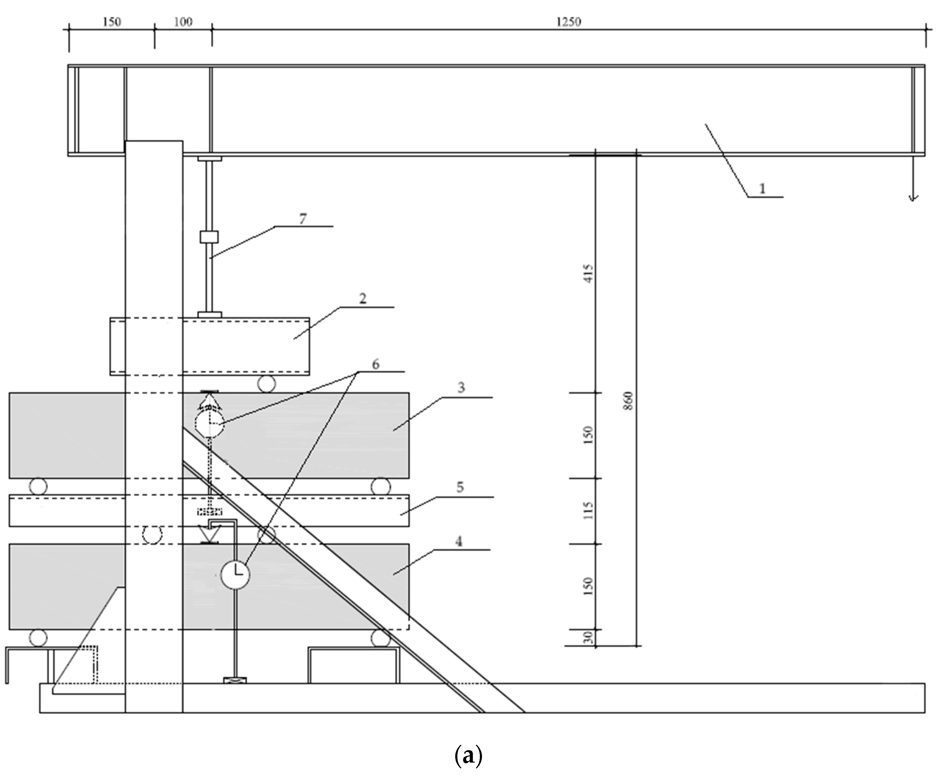
3.3. Testing Procedure

One LVDT was connected at the midspan of each tested TLB (see Figure 1). The load for testing the TLBs for creep was applied using special amplifying equipment. The testing setup scheme is shown in Figure 2. Figure 2a presents the detailed scheme of the testing setup, including the LVDT positions. Figure 2b shows the tested TLB specimens under loading.
The tests included the following loading cases:
-
Case 1. Two TLB specimens were tested under long-term loading, corresponding to 70% of the ultimate load;
-
Case 2. Two TLB specimens were previously loaded up to cracking and unloaded. After that, the specimens were tested under long-term loading, corresponding to 70% of the ultimate load;
-
Case 3. Two other TLB specimens were tested under long-term loading, corresponding to about 85% of the ultimate load.
According to the design, the ultimate load for the tested TLBs corresponded to 34.3 kN. The load was applied through a lever arm (see Figure 2a) with an amplifying ratio that equals (1250 + 100)/100 = 13.5. Using the lever arm allows achieving the desired load (24 kN for Cases 1 and 2 and 29.2 kN for Case 3) that acts on the tested TLB specimens.
The experiments lasted 90 days. CATMAN software (https://www.hbkworld.com/en/services-support/support/support-hbm/downloads/downloads-software/support-downloads-catman, accessed on 10 March 2025) [33] was used for data logging. Deflections were measured in the midspan of each TLB. During the first 24 h after applying the loading, the deflections were recorded every 10 s, and after 24 h, every hour.

4. Experimental Results and Discussion

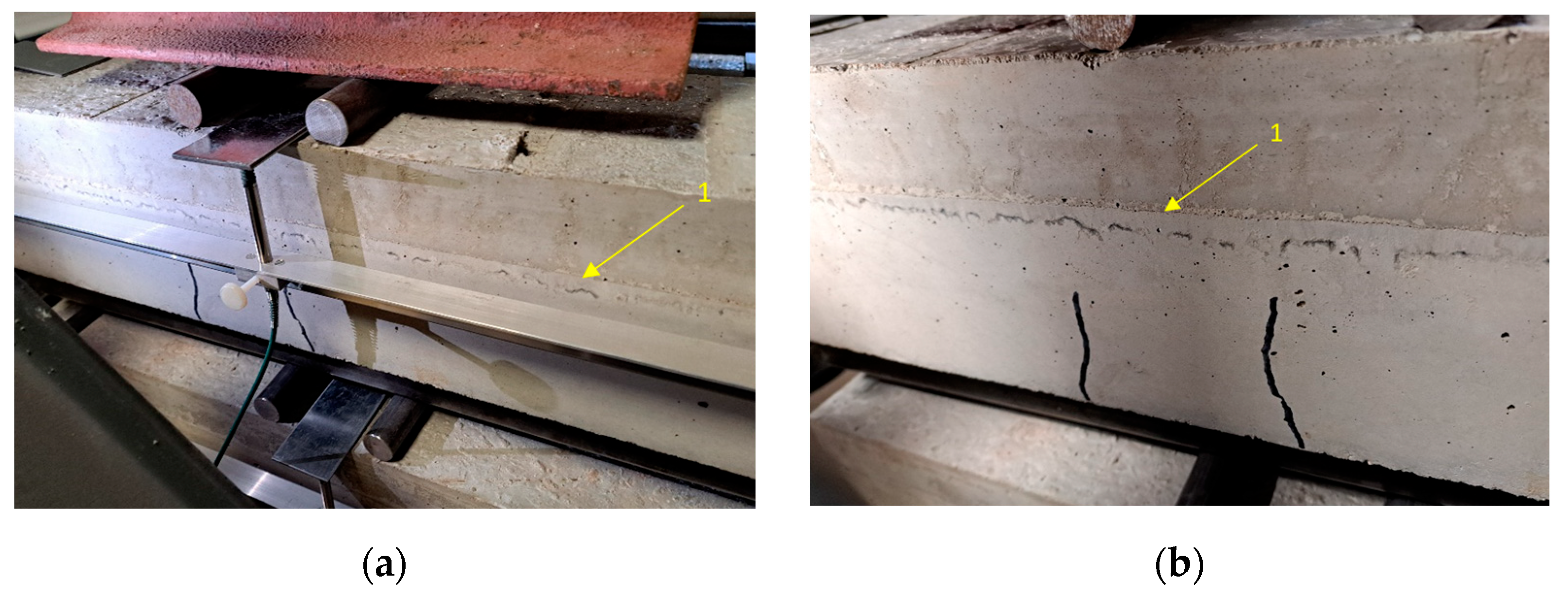
4.1. Beams’ Cracking

After applying the loads, crack formation and width in all tested TLBs were documented. The data on cracks’ opening are summarized in Table 3.
As it follows from the table, there were no cracks in the top beam loaded by 70% of the ultimate load (Case 1), whereas in the bottom beam, just one crack appeared. It can be explained by the fact that the bottom beam carries, in addition to the applied load, the self-weight of the upper beam as well as that of the steel beam and rods (see Figure 1).
In Case 2, the specimens were pre-cracked by applying 85% of the ultimate load, unloaded, and loaded again by 70% of the ultimate load. The second loading has not resulted in new cracks appearing, but the old ones have remained.
In the uncracked specimens subjected to 85% of the ultimate load (Case 3), three cracks appeared in the upper beam and two cracks appeared in the bottom one; however, the cracks’ depth in the bottom beam was higher than in the upper one. It should be mentioned that the cracks have not propagated to the SFHSC layer.
A typical pattern of cracks in the TLB specimens is shown in Figure 3. As it is evident from this figure, no cracks have been observed near the support as well as between the SFHSC and NSC layers. The cracks appeared within the limits of the pure bending zone. No de-bonding was observed between the NSC and SFHSC layers (see Figure 3). Typical cracks appeared in the NSC layer only.

4.2. Analysis of Linear Creep

As mentioned above, TLBs’ midspan deflections were measured and recorded under constant loading and climate-controlled conditions. The temperature in the climate room was 20 °C and the humidity—65%. Figure 4 presents the maximum values of midspan deflections in the tested TLBs due to linear concrete creep during the first 90 days according to the loading cases that were described in Section 3.3. As it follows from the graphs in the figure, in general the creep deflections’ development is linear.
As expected, the dominant case from the viewpoint of creep deflections is Case 3 (loading, corresponding to 85% of the ultimate load). Compared to Case 1 (loading, corresponding to 70% of the ultimate load), the deflections in Case 3 at 90 days are 2.33 times higher, which indicates high non-linear deformations in the tested beams. For pre-cracked TLBs subjected to 70% of the ultimate load (Case 2), the creep deflection growth is similar to Case 1, but the deflections’ values are about two times higher, which corresponds to the structural phenomenon [28].
Following the design codes [7,8], the deflection of beams corresponds to about 1/250 of their span. For the investigated TLB specimens, the span is 650 mm (see Figure 1), i.e., the deflections are limited by 2.6 mm. The maximum value of the midspan deflection that was obtained in the tested beams in Case 3 is 0.42 mm; therefore, at linear creep, the TLBs are safe. Moreover, considering the fact that for the measured deflections’ values, the compressed concrete deformations are εc ≤ 0.5‰ [15], therefore, it is evident that the tested TLBs are within the elastic stage. This fact is very important for the beams’ design considering linear creep.
At the same time, the lifetime of real beams is much longer than 90 days. It can be assumed that at a certain stage, non-linear creep will appear in TLBs. Therefore, it was decided to continue the tests over 90 days to obtain data on non-linear creep. It will allow comparing these data on TLBs with the available ones from the design codes to investigate the behavior of TLBs considering non-linear creep. This will be the main aim of our further research.

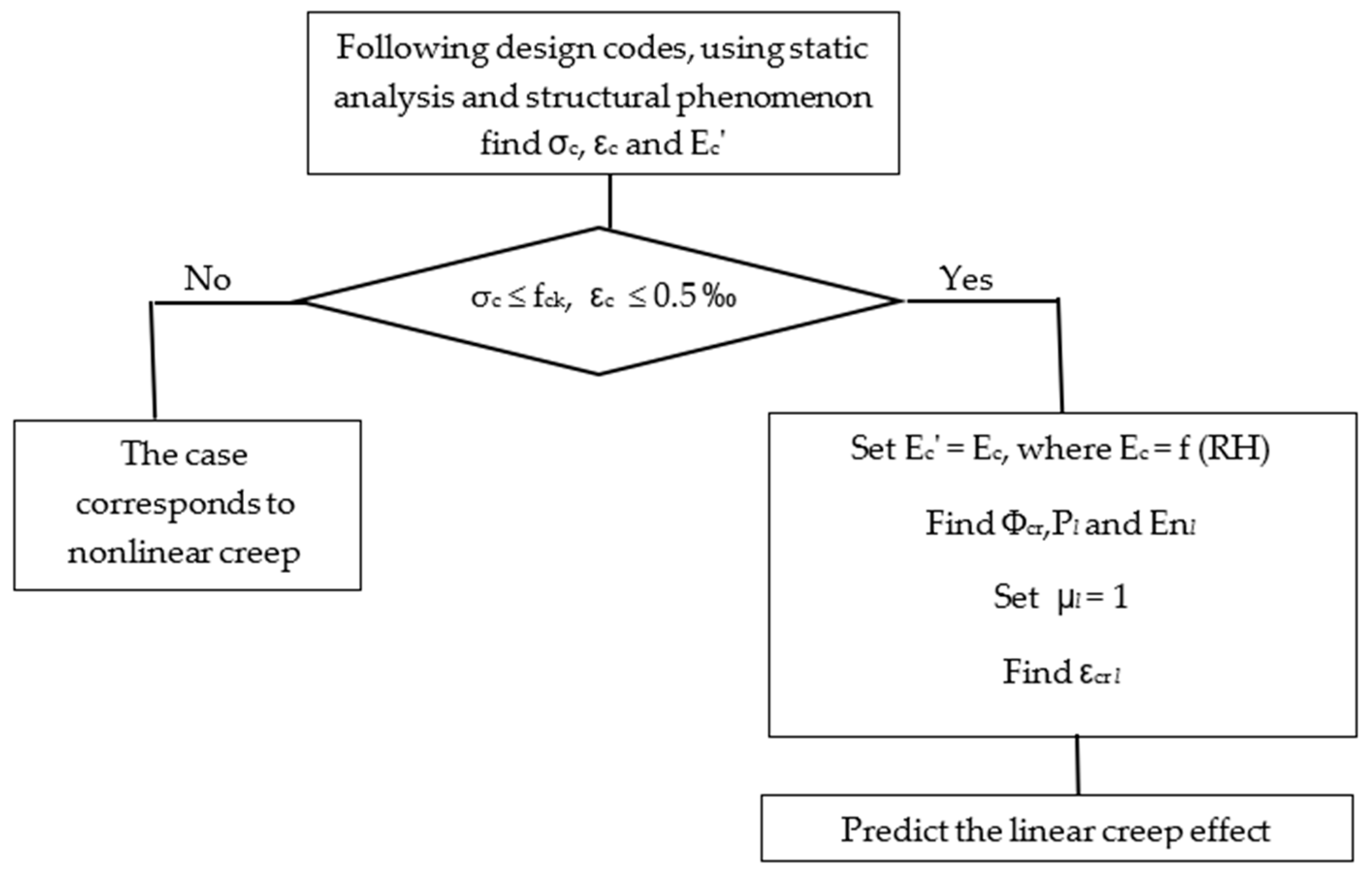
5. Concrete Linear Creep Algorithm

The authors have previously proposed an algorithm for concrete creep evaluation [7]. The algorithm is based on the following hypotheses:
-
According to modern codes, concrete creep increases up to 4–5 years, and after that it asymptotically approaches a constant value, but the main effect is achieved during the first year;
-
Uniaxial concrete compression at constant stress was assumed;
-
The concrete creep increases as an exponential curve that becomes practically parallel to the time axis.
The algorithm was proposed for ordinary concrete classes [15] without considering the surrounding environment humidity and concrete mixture proportioning aspects. In the present study, the experiments were carried out in a climate room with controlled temperature and humidity; therefore, the algorithm is suitable for analyzing linear creep in the tested TLBs. A scheme of the algorithm is presented in Figure 5. All symbols in this figure correspond to the design codes [7,8,15].
Following the experiments, the tested TLBs under all load levels (Cases 1, 2, and 3) behaved without debonding between the layers. It was a proper interaction between the NSC and SFHSC layers. Therefore, the algorithm for linear creep for single-layer beams [15] can be used for TLBs too.

6. Conclusions

Results of the experimental investigation of linear creep in two-layer reinforced concrete beams are presented. Methodology for testing the creep behavior of reinforced concrete beams was developed. Special amplifying devices with lever arms were used to apply the long-term loads on the investigated specimens.
The experimental results show that it is possible to use the previously proposed algorithm in order to evaluate the linear creep effect in two-layer reinforced concrete beams.
The maximum midspan deflection in the tested beams was less than 1/250 of the beam span, which indicated that at linear creep, the two-layer beams are safe and remain in the elastic stage.
The obtained results form a basis for the next stage of the experimental research that will be focused on the non-linear creep effect in such beams.

Author Contributions

Conceptualization, I.I., K.H. and Y.R.; methodology, K.H. and S.K.; software, S.K.; validation, I.I., S.K. and Y.R.; formal analysis, S.K.; investigation, I.I., K.H., S.K. and Y.R.; resources, K.H. and Y.R.; data curation, S.K.; writing—original draft preparation, I.I., S.K. and Y.R.; writing—review and editing, I.I. and Y.R.; visualization, I.I., S.K. and Y.R.; supervision, K.H.; project administration, K.H.; funding acquisition, K.H. and Y.R. All authors have read and agreed to the published version of the manuscript.

Funding

This research was funded by the Alexander von Humboldt Foundation, Germany, ref. 1070064.

Institutional Review Board Statement

Not applicable.

Informed Consent Statement

Not applicable.

Data Availability Statement

The original contributions presented in the study are included in the article, further inquiries can be directed to the corresponding author.

Conflicts of Interest

The authors declare no conflicts of interest.

References

  1. Shi, X.; Park, P.; Rew, Y.; Huang, K.; Sim, C. Constitutive behaviors of steel fiber reinforced concrete under uniaxial compression and tension. Constr. Build. Mater. 2020, 233, 117316. [Google Scholar]
  2. Xu, H.; Wang, Z.; Shao, Z.; Cai, L.; Jin, H.; Zhang, Z.; Qiu, Z.; Rui, X.; Chen, T. Experimental study on durability of fiber reinforced concrete: Effect of cellulose fiber, polyvinyl alcohol fiber and polyolefin fiber. Constr. Build. Mater. 2021, 306, 124867. [Google Scholar]
  3. De Azevedo, A.R.; Marvila, M.T.; Tayeh, B.A.; Cecchin, D.; Pereira, A.C.; Monteiro, S.N. Technological performance of açaí natural fibre reinforced cement-based mortars. J. Build. Eng. 2021, 33, 101675. [Google Scholar]
  4. Song, P.; Hwang, S. Mechanical properties of high-strength steel fiber-reinforced concrete. Constr. Build. Mater. 2004, 18, 669–673. [Google Scholar]
  5. Jindra, D.; Hradil1, P.; Kala, J. Stress relaxation of concrete beams caused by creep and shrinkage effects. MATEC Web Conf. 2024, 396, 05018. [Google Scholar] [CrossRef]
  6. Ghali, A.; Favre, R.; Eldbadry, M. Concrete Structures. Stresses and Deformation; Taylor & Francis: New York, NY, USA, 2002. [Google Scholar]
  7. EN 1992-1-1; Eurocode 2: Design of Concrete Structures—Part 1-1: General Rules and Rules for Buildings. 2004. Available online: https://archive.org/details/bs_en_1992-1-1-2004_eurocode_2 (accessed on 10 December 2024).
  8. SI 466 part 1; The Standards Institution of Israel. Concrete Code: General Principles. Amendment 3. 2012. Available online: https://docplayer.gr/106673223-Si-466-part-1-june-amendment-no-4-the-standards-institution-of-israel-concrete-code-general-principles-november-2016.html#google_vignette (accessed on 10 December 2024). (in Hebrew)
  9. ACI Committee 318-05; Building Code Requirements for Structural Concrete. 2005. Available online: https://www.concrete.org/Portals/0/Files/PDF/Previews/318-05_preview.pdf (accessed on 10 December 2024).
  10. BR 52-101-2003; Non-Pre-Stressed Concrete and Reinforced Concrete Structures. NIIZhB: Moscow, Russia, 2004. (In Russian)
  11. Model Code 2010, final draft, vol. 1; Bulletin 65; Federation Internationale du Beton (fib): Lausanne, Switzerland, 2012; Volume 2.
  12. Marzouk, H. Creep of high–strength concrete and normal–strength concrete. Mag. Concr. Res. 1991, 43, 121–126. [Google Scholar] [CrossRef]
  13. Zhou, Y.; Chen, W.; Yan, P. Measurement and modeling of creep property of high-strength concrete considering stress relaxation effect. J. Build. Eng. 2022, 56, 104726. [Google Scholar] [CrossRef]
  14. Dias-da-Costa, D.; Júlio, E.N.B.S. Modelling creep of high strength concrete. Comput. Concr. 2010, 7, 533–547. [Google Scholar]
  15. Iskhakov, I.; Ribakov, Y. New Model of Linear and Non- linear Concrete Creep. Rom. J. Mater. 2021, 51, 528–535. [Google Scholar]
  16. Xue, W.; Liu, T.; Zeng, M. Prediction of long-term deflections for high-speed railway prestressed concrete beams. ACI Struct. J. 2016, 113, 769–778. [Google Scholar] [CrossRef]
  17. Pan, Z.; Lü, Z.; Fu, C.C. Experimental study on creep and shrinkage of high-strength plain concrete and reinforced concrete. Adv. Struct. Eng. 2011, 14, 235–247. [Google Scholar]
  18. Yang, M.; Jin, S.; Gong, J. Concrete creep analysis method based on a long-term test of prestressed concrete beam. Adv. Civ. Eng. 2020, 2020, 3825403. [Google Scholar] [CrossRef]
  19. Tho, P.D.; Tien, T.M.; Thanh, D.T.; Ngan, V.M.; Ngoc, V.M.; Sorelli, L. Experimental investigation of the secondary creep of fiber reinforced concrete at high stress: Macroscopic measurement and digital image correlation. J. Sci. Technol. Civ. Eng. 2022, 16, 19–28. [Google Scholar] [CrossRef]
  20. Abrishambaf, A.; Barros, J.A.O.; Cunha, V.M.C.F. Time-dependent flexural behaviour of cracked steel fibre reinforced self-compacting concrete panels. Cem. Concr. Res. 2015, 72, 21–36. [Google Scholar]
  21. García-Taengua, E.; Arango, S.; Martí-Vargas, J.R.; Serna, P. Flexural creep of steel fiber reinforced concrete in the cracked state. Constr. Build. Mater. 2014, 65, 321–329. [Google Scholar]
  22. Cao, X.Y.; Feng, D.C.; Wu, G.; Wang, Z. Experimental and Theoretical Investigations of the Existing Reinforced Concrete Frames Retrofitted with the Novel External SC-PBSPC BRBF Sub-Structures. Eng. Struct. 2022, 256, 113982. [Google Scholar] [CrossRef]
  23. Wang, H.T.; Tang, C.; Chen, M.S.; Shi, J.; Cao, X.Y. Experimental Study on the Flexural Performance of Prestressed RC Beams with Post-Tensioned CFRP Strands. Eng. Struct. 2024, 309, 118118. [Google Scholar] [CrossRef]
  24. Iskhakov, I.; Ribakov, Y.; Holschemacher, K.; Mueller, T. Experimental Investigation of Full Scale Two-Layer Reinforced Concrete Beams. Mech. Adv. Mater. Struct. 2014, 21, 273–283. [Google Scholar]
  25. Iskhakov, I.; Ribakov, Y.; Holschemacher, K. Experimental Investigation of Continuous Two-Layer Reinforced Concrete Beam. Struct. Concr. 2016, 18, 205–215. [Google Scholar]
  26. Iskhakov, I.; Ribakov, Y.; Holschemacher, K.; Kaesberg, S. Experimental Case study and Recommendations for Practical Implementation of Real Pre-Stressed Two Layer Reinforced Concrete Beams. Structures 2023, 47, 1284–1294. [Google Scholar]
  27. STRAP—Structural Analysis Programs. ATIR Engineering Software Development, Users’ Manual. 2021. Available online: https://atirsoft.com/wp-content/uploads/2020/09/STRAP_Manual.pdf (accessed on 29 January 2025).
  28. Iskhakov, I.; Ribakov, Y. Structural Phenomenon of Cement-Based Composite Elements in Ultimate Limit State. Adv. Build. Technol. Constr. Mater. 2016, 2016, 4710752. [Google Scholar]
  29. Deutscher Beton- und Bautechnik-Verein e.V. (Hrsg.). DBV-Merkblatt Stahlfaserbeton; Deutscher Beton- und Bautechnik-Verein e.V.: Wiesbaden, Germany, 2001. (In German) [Google Scholar]
  30. Deutscher Ausschuss für Stahlbeton (DAfStb). Richtlinie Stahlfaserbeton; 23. Entwurf; Beuth Verlag GmbH: Berlin/Köln, Germany, 2007. (In German) [Google Scholar]
  31. DIN 1045-1; Tragwerke aus Beton, Stahlbeton und Spannbeton—Teil 1 Bemessung und Konstruktion. DIN Deutsches Institut für Normung e.V: Berlin, Germany, 2008. Available online: https://regbar.com/ar/wp-content/uploads/2019/09/DIN-1045-1-2008.pdf (accessed on 10 December 2024). (In German)
  32. Junker, F.; Holschemacher, K. Creep Behavior of Steel Fiber Reinforced Lightweight Concrete Beams Under Flexural Loading. Proc. Int. Struct. Eng. Constr. 2022, 9, 1–6. [Google Scholar] [CrossRef]
  33. HBM (Hottinger Baldwin Messtechnik GmbH) Software: Catman Professional Rel. 4.5. 2004. Available online: https://www.hbkworld.com/en/services-support/support/support-hbm/downloads/downloads-software/support-downloads-catman (accessed on 10 March 2025).
Figure 1. Dimensions and loading scheme of the tested TLBs [32].
Applsci 15 03456 g001
Figure 2. The testing setup: (a) the amplifying equipment scheme: 1—lever arm, 2—upper traverse, 3—upper TLB, 4—lower TLB, 5—lower traverse, 6—LVDTs, 7—jack; (b) a view of all 6 tested TLB specimens under loading.
Applsci 15 03456 g002aApplsci 15 03456 g002b
Figure 3. A typical pattern of cracks in the TLBs: (a) general view; (b) fragment of the beam’s cracked zone, 1—border between the SFHSC and NSC layers.
Applsci 15 03456 g003
Figure 4. Maximum midspan deflections in the tested TLBs due to linear creep during the first 90 days.
Applsci 15 03456 g004
Figure 5. Algorithm for linear creep analysis (following [12]). Codes [7,8,9,10,11] Structural phenomenon [28].
Applsci 15 03456 g005
Table 1. Concrete mixture compositions.
ComponentsQuantity, kg/m3
SFHSCNSC
Cement (C)400300
Water (W)152180
Fly ash (FA)1000
Superplasticizer15.40
0/2 sand675.43659.36
2/8 gravel429.71560.91
8/16 gravel618.78654.40
Table 2. Strength of SFHSC (FWR = 40 kg/m3, MPa).
CompressiveSplitting Tensile
96.526.14
95.516.27
94.815.93
Table 3. Cracks’ width in the TLBs immediately after loading.
Load CaseSpecimenCracks’ Opening, mm
Crack 1Crack 2Crack 3
DepthWidthDepthWidthDepthWidth
1Top------
Bottom800.1----
2Top700.1700.1700.1
Bottom1000.1700.1--
3Top800.1800.1600.1
Bottom1000.11000.1--
Disclaimer/Publisher’s Note: The statements, opinions and data contained in all publications are solely those of the individual author(s) and contributor(s) and not of MDPI and/or the editor(s). MDPI and/or the editor(s) disclaim responsibility for any injury to people or property resulting from any ideas, methods, instructions or products referred to in the content.

