1. Introduction
Concrete is strongly known for its high compressive strength; nonetheless, because of its inherent brittleness and small tensile strength, it is prone to cracking under various loading conditions. Crack initiation and crack growth are crucial to investigating concrete structures’ energy capacity of dissipation, particularly under cyclic and dynamic loading conditions. At the onset of crack initiation, energy is expended to overcome the material’s cohesive strength and create new crack surfaces. This process contributes to the fracture energy, which is a significant component of the total energy dissipation in the material. Under further loading, micro-cracking and plastic deformations are initiated at the crack tip, contributing to energy dissipation. However, when an extensive crack forms uncontrollably in plain, unconfined concrete, it reduces the load-carrying capacity and energy dissipation. This redaction produces a smaller hysteresis loop area that restricts the material from absorbing energy.
To overcome the weaknesses of concrete behavior, fiber-reinforced concrete (FRC) has been developed to enhance concrete’s tensile performance and energy absorption. Fibers in the concrete matrix function as crack-bridging reinforcements, altering the crack propagation mechanism. Fibers transfer tensile loads across crack surfaces upon crack formations, requiring additional energy for crack propagation. This action increases ductility and extends the hysteresis loop area under cyclic loading. Instead of a single catastrophic fracture, fiber-reinforced composites promote a micro-crack-distributed formation, each of which helps in energy dissipation. Moreover, fibers exert frictional resistance and pull-out mechanisms, dissipating energy as cracks propagate through the material.
Several experimental and analytical studies have examined the effectiveness of fibers in enhancing the toughness and energy-dissipating capability of concrete at a fracture. It was demonstrated that adding rubber powder and recycled steel fibers (RSF) significantly increased the ductility of concrete, and it has been established that fibers ensure a more controlled process of crack growth through damage distribution [
1]. Similarly, it was shown that the crack bridging by fibers is a prevailing mechanism of toughening, which is more energy intensive for crack growth and contributes towards improved energy absorption [
2]. It was stated that ultra-high-performance concrete (UHPC) exhibited superior mechanical performance by way of controlled micro-cracking and fiber pull-out, both contributing towards improved energy dissipation due to the distributing of damage over greater material volume [
3]. It was further demonstrated that the incorporation of fibers led to a spectacular increase in fracture energy, with rises of 850%, 770%, and 450% being reported for various concrete strengths [
4]. The significance of the fiber pull-out and crack bridging mechanisms was proved through advanced 3D imaging techniques, and it was concluded that 3.5–4.0% steel fiber volumes led to a hundred-fold rise in energy dissipation [
5].
The above findings were supported by analyzing the flexural behavior of hybrid polypropylene and SFRHSC beams, demonstrating that fiber interaction significantly enhanced post-cracking toughness and delayed crack localization, emphasizing the role of fibers in triggering distributed damage and promoting energy dissipation [
6]. Additional details were provided on the uniaxial tensile response of ultra-high-performance fiber-reinforced concrete (UHPFRC) [
7], which indicated that the fibers resulted in a more dispersed cracking pattern and an appreciable enhancement in energy absorption capacity. The contribution of fiber content in determining the post-cracking tensile stiffness of fiber-reinforced UHPFRC was emphasized, showing that higher fiber volume fractions led to higher energy dissipation due to more energy being required to extend cracks in the material [
8]. Finally, the Lattice Discrete Particle Model (LDPM) was used to investigate UHPFRC fracture behavior by focusing on the synergistic fiber pull-out and bridging effects, which raised the energy-absorbing capacity and ability of crack propagations [
9].
These experiments collectively indicate that the effectiveness of fibers is due to a variety of interrelated mechanisms: (1) crack bridging, which redistributes stress over crack surfaces and delays crack widening; (2) fiber pull-out, which contributes frictional resistance to crack opening; (3) micro-cracking under control, which spreads damage over a larger area; (4) plastic deformation of the matrix material around the fibers; and (5) debonding at interfaces, which requires energy to separate fibers from the matrix. The synergistic functions of such mechanisms significantly enhance the energy absorption capacity of fiber concrete compared to plain concrete.
Understanding these mechanisms is essential in maximizing the fiber-reinforced, high-strength, and ultra-high-performance concrete design, particularly for applications involving energy absorption and crack resistance to seismic and impact loading. By preventing uncontrolled crack propagation and promoting distributed damage, fibers ensure that the material can withstand higher deformation levels while dissipating more energy.
In addition, studies conducted on two-layer beams demonstrated that the application of steel fiber high-strength concrete (SFHSC) in the compression zone and normal-strength concrete (NSC) with reinforcement in the tension zone significantly enhances structural ductility, energy absorption, and cracking resistance [
10,
11]. Steel fibers’ ability to improve toughness is well established, as they increase strain at peak stress, and also increase the secant modulus of elasticity [
12]. Furthermore, the content of fibers can be managed to improve ductility levels, which makes FRC extremely suitable for seismic-resistant designs [
10]. FRC compressive behavior depends on several parameters encompassing the strength of concrete, fiber content, and fiber aspect ratio. Studies show that increasing the fiber content increases the strain at peak compressive strength, and the elastic modulus reduces marginally [
13].
This work expands previous studies by further investigating the crack growth, extension, and energy dissipation behavior in fiber-reinforced concrete using more advanced modeling techniques and available experimental data. This study is focused on numerical modeling of the steel fiber-reinforced compressed zone behavior based on the results of previous work on two-layer beams [
10,
11]. Specifically, we focus on optimizing fiber content at the compressed zone. The design utilizes materials’ properties and optimizes structural performance with higher cracking resistance in cyclic loading conditions.
2. Lattice Discrete Particle Model
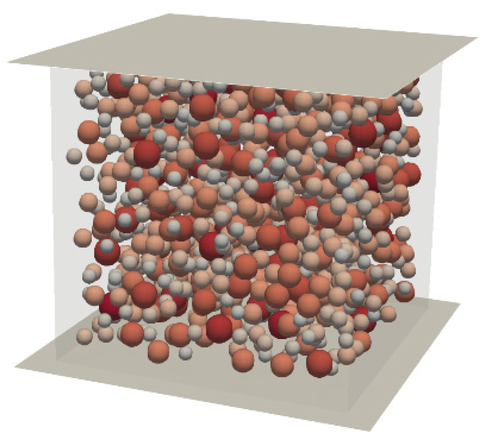
The Lattice Discrete Particle Model (LDPM) can be used to characterize the mesostructure of concrete as a three-dimensional assembly of discrete particles. This mesostructure consists of coarse aggregates embedded within a cementitious mortar matrix. The LDPM method begins by positioning spherical aggregate particles randomly inside the specimen volume according to a particle size distribution based on the Fuller equation [
14] and applying spatial placement functions like uniform or other probabilistic ones. A specialized spatial discretization technique is then employed to connect each aggregate to its adjacent mortar and aggregates, usually using a modified Voronoi tessellation to partition the space efficiently.
Four neighboring aggregates form tetrahedral elements in the LDPM model, which define the mechanical particle–particle interactions. The nodes at the centers of the aggregates are the tetrahedra’s vertices, each possessing six degrees of freedom—three translational and three rotational. Mechanical response is defined by constitutive relations on triangular facets that simulate the interfaces between aggregates. The facets capture significant mechanical events, including elastic deformation, plasticity, damage, and fracture. Numerical solutions are typically achieved using explicit time-stepping schemes, enabling the model to effectively handle quasi-static and dynamic loading conditions.
Cracking in the LDPM is limited to the mortar matrix because the aggregates are represented as rigid, non-fracturable inclusions in its standard formulation. While computationally beneficial, such an approximation can restrict the model’s accuracy when simulating high-strength concrete or large, voided concrete, or when under high strain rates. Yet, more recent efforts [
15] applied localized aggregate discretization techniques to overcome this limitation and enable fracture to traverse large aggregates. The constitutive behavior of the facets encompasses elastic and inelastic responses, compaction under compression, pore collapse, and damage evolution, and model parameters are calibrated based on standard experimental tests. Crack propagation is simulated as the fragmentation of polyhedral cells around aggregates after the locally exceeded damage threshold value. LDPM has been shown to have an excellent ability to mimic the fracture behavior of concrete under a wide variety of loading conditions [
16,
17,
18,
19,
20].
2.1. Fiber Modeling and Crack-Bridging Mechanism
Concrete requires reinforcement for the purposes of enhancing its tensile capacity, as well as ductility since it is brittle under tensile loading. Fiber-reinforced concrete (FRC) has a complex interrelation between fibers and the confining concrete matrix at the mesoscale that controls it. The tensile brittleness of concrete generates the early initiation and propagation of cracks, while fibers dispersed within the matrix constrain the cracking phenomenon through a crack-bridging mechanism. The influence of fibers on the concrete behavior can be modeled in the Lattice Discrete Particle Model with Fibers (LDPM-F) that extends the parent LDPM with discrete, randomly distributed, and randomly oriented fibers in the concrete mesostructure [
21]. Once a crack is formed, bridging fibers restrain its growth by creating a bridging force
Pf, which is a function of the slip of the fiber concerning the crack opening—the slip is denoted as
. Fibers carry the load by bridging the crack when a crack is formed. The crack-bridging force
Pf of a fiber provided for LDPM is a function of its slippage
which describes the relative displacement between the fiber and the matrix at the crack interface.
The bridging force can be divided into the debonding phase and the pull-out phase, each of which is defined by some governing equations. In the debonding phase (
), the fiber–matrix bond is progressively lost with the opening of the crack, and the fiber begins to slip. The semi-empirical expression gives the bridging force in this context:
where E
f denotes the elastic modulus of the fiber,
df denotes the fiber diameter,
denotes the bond stress,
Gd denotes the debonding fracture energy, and
denotes the critical slippage at which complete debonding occurs. This equation captures the increase in load resistance as the slip progresses, up to the point where complete debonding occurs. Following debonding, the pull-out stage (
) initiates, where frictional resistance and mechanical interlocking (e.g., hooked or waved fibers) govern the residual load-carrying capacity. This stage is defined by the relationship:
where
denotes the maximum pull-out force,
denotes the embedment length of the fiber within the matrix, and
β denotes a dimensionless parameter that controls the slip-hardening (
β > 0), slip-softening (
β < 0), or neutral (
β = 0) behavior during the pull-out process. As the fiber continues to slip out of the matrix, the bridging force gradually decreases until the fiber is fully extracted, unless fiber rupture occurs before complete pull-out.
Figure 1 illustrates the relationship between load and slippage for different values of
β.
In addition, other micromechanical effects govern the fiber–matrix interaction during pull-out, which are accounted for in LDPM-F. These are spalling at the crack interface, snubbing effects, and the Cook–Gordon mechanism. Spalling refers to the local debonding and damage of the matrix in front of the fiber exit point, which decreases the effective embedment length. This effect is modeled by reducing the embedment length as a function of the matrix’s bridging force and tensile strength. The snubbing effect is when fibers are at an angle to the crack plane, resulting in additional resistance due to the bending of the fiber around the matrix corner. An exponential increase factor typically models it as a function of the fiber angle and snubbing coefficient. The Cook–Gordon mechanism can simulate the premature debonding of fibers in front of an advancing crack tip, considering an additional slip component that affects the crack opening. These interactions can be represented as:
where
PfN denotes the normal part of the bridging force,
θ denotes the angle between the embedded fiber and the normal fiber orientation of the facet,
σt denotes the tensile strength of the matrix, and
ksp denotes an empirical coefficient that can be calibrated.
where
is the angle between the fiber in the matrix and deflected fiber after spalling for the same fiber, and
ksn is a coefficient to be calibrated.
where
kcg denotes the Cook–Gordon coefficient of the premature slip due to initiated cracks.
The fiber load must not exceed the rupture strength, with a demand that:
where
denotes the material parameter and is the ultimate tensile strength of the fiber. When this condition fails, the fiber load is set to zero.
For an embedded fiber at the two sides of a crack opening ω, the crack-bridging force is expressed as:
where the bridging segment satisfies:
where
and
are the slip components of the fiber’s embedment lengths.
The resisting pull-out forces on the two sides must be equal:
An iterative solution procedure is needed due to the nonlinearity in the computation of the fiber bridging force caused by the spalling length and slip response’s dependence on the evolving crack opening. The procedure begins with a starting approximation of the fiber force, pf, from the previously computed value. From this estimate, the spalling length sf and effective embedment lengths are calculated, which define the bridging segment’s geometry. Compatibility between the slip value and the crack opening is enforced by solving for relative slip components, , with Brent’s method. This numerical approach iteratively adjusts the slip values to satisfy equilibrium conditions between the pull-out resisting forces on both sides of the crack. Finally, the computed fiber bridging force is validated using the fiber rupture criterion to ensure structural safety once the convergence occurs. Where the calculated force is greater than the ultimate tensile strength of the fiber, the adjustment is made accordingly to prevent overestimation of the bridging capacity.
These micro-scale interactions collectively control the macro-scale toughness and ductility of fiber-reinforced concrete. Fibers, especially steel and synthetic macro-fibers, enhance the ability of the concrete to withstand energy during cracking by restraining crack propagation and increasing the work needed for total separation. The ensuing multi-cracking, as opposed to the single dominant crack in plain concrete, enhances the post-cracking load-carrying capacity and the structural response under tensile and flexural loading. This energy absorption capacity is even enhanced under cyclic loading, with fibers bridging opening and closing cracks, leading to typical hysteresis loops. The area of the hysteresis loop is proportional to the energy dissipation capacity of the material, a basic property for seismic uses.
LDPM-F offers an effective numerical means to simulate these fiber-induced improvements in the behavior of concrete. Coupling fiber–matrix interactions at the mesoscale bridges the gap between the micro-scale pull-out response and the global structural response. Through this multi-scale modeling, LDPM-F is capable of simulating intricate crack propagation patterns, such as multi-cracking and fiber-bridging, and thereby accurately predicting FRC behavior under static and dynamic loading. Micromechanical modeling of the mechanisms enables the optimization of the fiber type, volume fraction, and geometry to achieve the required mechanical characteristics of FRC for a given structural application. A comprehensive investigation into the calibration and validation process of the LDPM-F was provided [
23], highlighting its capacity to accurately simulate the mechanical behavior of polypropylene and steel fiber-reinforced concrete under different loading conditions.
2.2. LDPM Cyclic Behavior
Realistic energy dissipation is crucial in the cyclic loading context to reproduce the behavior of concrete subjected to seismic loading. Two parameters, kt and kc, dominate in controlling the energy dissipated under cyclic tension and compression loading, respectively, in the Lattice Discrete Particle Model (LDPM).
The parameter kt drives the residual plastic strain and form of the unloading and reloading curves due to tensile cycling. If a specimen is unloaded from the tensile envelope curve, the residual plastic strain is given as:
where
εN,max denotes the maximum normal strain,
σN,max corresponds to the maximum stress, and
EN denotes the elastic modulus.
Increasing the kt value increases the residual plastic strain, shifting the reloading curve along the strain axis. This shift makes reloading intersect the envelope curve later, decreasing the hysteresis loop’s area. Dissipated energy under cyclic loading is therefore decreased. On the other hand, this decreases the residual plastic strain, making reloading occur earlier and leading to a larger hysteresis loop, increasing the dissipated energy.
The parameter
kc governs the reloading strain in compression after unloading. The reloading limit strain is given as:
where
denotes the residual plastic strain in compression.
When kc is increased, the reloading strain is greater, and the stress will be zero for a greater range of strain before reloading. This influence minimizes the area within the stress–strain loop and, thereby, the energy dissipation. On the other hand, reduction shifts the reloading curve nearer to the unloading point, decreasing the extent of strains throughout, wherein there is zero stress. This redaction increases the area beneath the loop and dissipates energy with the loading cycle.
Both
kc and
kt influence the size and shape of the hysteresis loops in cyclic tension and compression, which are necessary measures of the energy dissipation capability of concrete under seismic loading. The calibration of these parameters is essential to properly reflect experimental tests’ plastic deformation and energy dissipation behavior. The modified LDPM model [
24] integrates these parameters to eliminate shortcomings in the original cycling law to enhance the simulation of the behavior of concrete subjected to different loading states, such as uniaxial tension–compression, hydrostatic pressure, and triaxial compression.
3. Model Calibration
To mimic the behavior of fiber-reinforced concrete specimens, we initially calibrated the LDPM by fitting macroscopic numerical results with the available experimental data [
10]. The compressive and splitting tensile strengths of the concrete were determined based on experiments on six cubes with an edge length of 15 cm [
10]. The geometrical sizes of the simulations were designed to be in accordance with the experiment.
LDPM has a double parameter set consisting of the mixing design parameters that are directly involved in the experimental concrete mixture design: cement consumption 400 kg/m
3, water demand 132 kg/m
3, and the aggregates consisting of 0/2 mm sand 39%, 2/8 mm gravel 25%, and 8/16 mm gravel 36%. The mechanical parameters form the second set of parameters calibrated against the experimental uniaxial compression data by fitting the compressive strength to 90 MPa. The full details of the mix design and mechanical parameters are listed in
Table 1 and
Table 2. The geometry of the specimen for the uniaxial compressive test is shown in
Figure 2. To ensure numerical stability and quasi-static conditions, we calibrated the maximum time step based on the minimum aggregate size, the smallest finite element, and the material density to prevent instability, i.e., an uncontrollable increase in kinetic energy. The platen movement was assigned with a velocity rate, having a constant acceleration step especially adjusted to match the quasi-static conditions under which kinetic energy is significantly lower than internal work but yet gives acceptable computational efficiency. Also, to make sure that there were no undesirable dynamic effects, we verified that the stress in the top and bottom platens remained constant during the simulation.
Having determined the mechanical concrete parameters by calibration to plain concrete, we next calibrated the fiber parameters with the uniaxial compression experiment of 20 kg/m
3 fiber content cubes. The curve-fitted experimental data from the calibration yielded a compressive strength of 90.826 MPa; the experiments had a standard deviation of ±4.150 MPa. The calibrated LDPM concrete and fiber parameters are shown in
Table 3.
4. Results
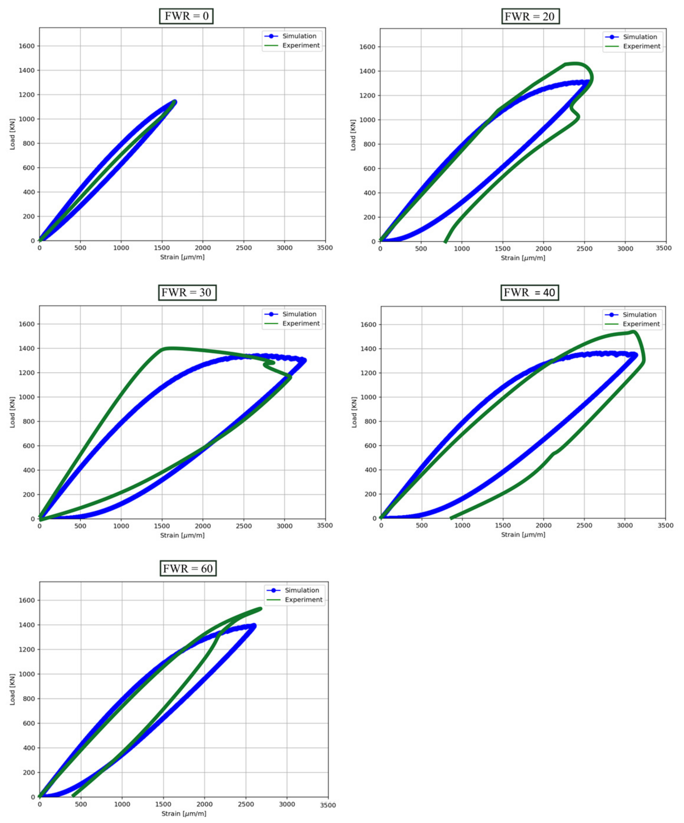
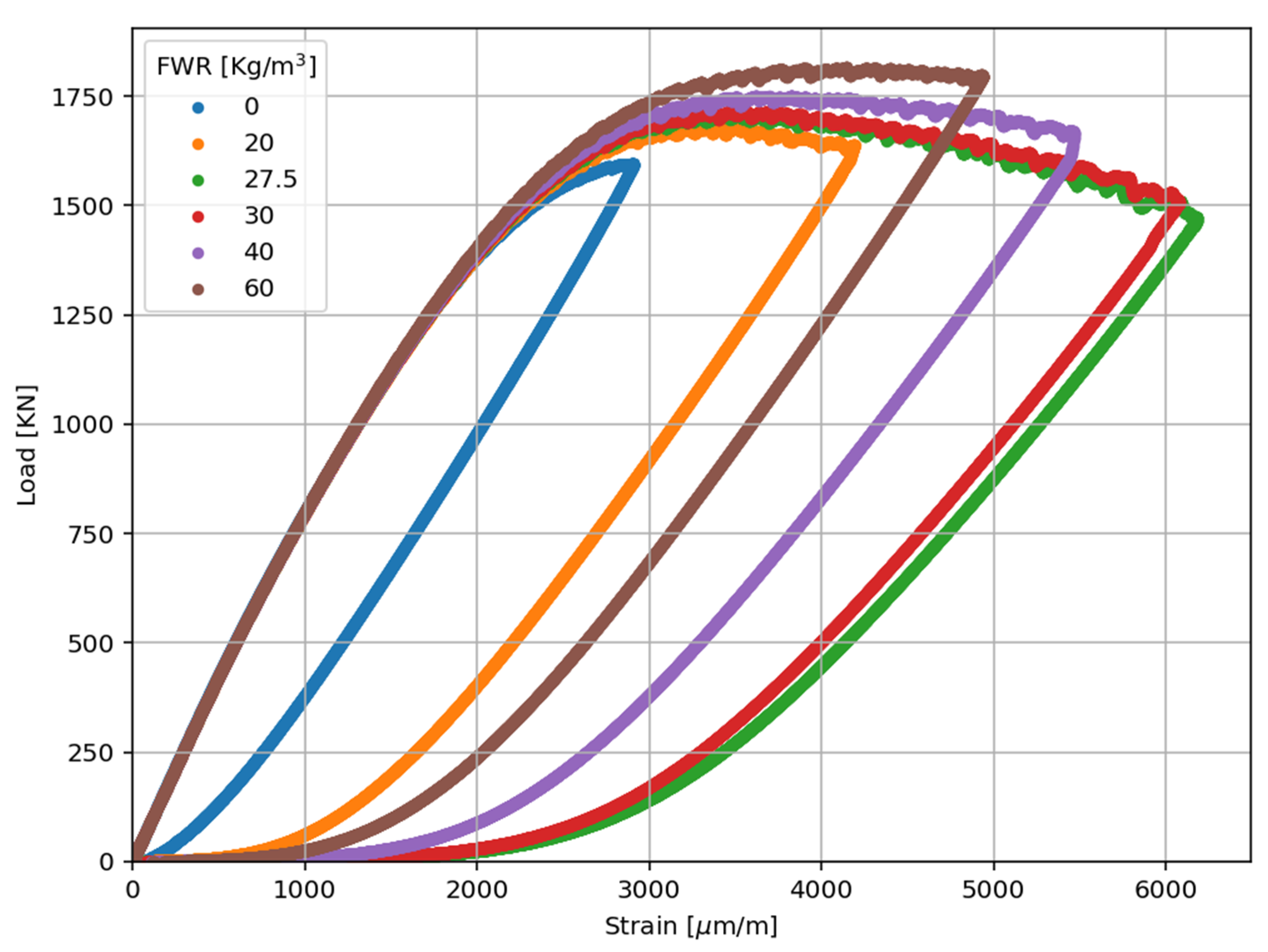
The experimental results were further simulated for the tests of fiber-reinforced concrete cylinder specimens with fiber weight ratio (FWR) values of 0, 20, 30, 40, and 60 kg/m
3 [
10], highlighting the effect of fiber content on structural performance. Following the available experimental data, three cylindrical specimens (30 cm high and with a diameter of 15 cm) were tested for each fiber content.
The presence of the fibers led to significant enhancements in the ultimate displacements obtained in the experiment, and their main contributions were toward plastic energy dissipation (PED). Numerical simulations in the frame of this present study have been performed in order to simulate the experimental results on the displacement behavior, energy dissipation, and ductility enhancement noted for the tested specimens. A detailed comparison between the experimental and simulated results for load strain for FWR of 0, 20, 30, 40, and 60 kg/m
3 is presented in
Figure 3.
First, the experimental and calculated values of dissipated energy from the hysteresis loop were compared. The dissipated energy,
W, can be expressed as:
For FWR = 0 kg/m
3, the experimental measurements indicate zero energy dissipation (see
Table 4), whereas the simulations yield a non-zero value of 0.189681 kN/m. This discrepancy is most likely due to measurement limitations rather than an issue with the numerical model. In brittle materials like plain high-strength concrete, failure occurs rapidly after reaching the peak load, making it challenging to capture post-peak energy dissipation experimentally. Since no data were recorded after the peak load in the experiments, the dissipation reported is considered zero, although in reality, some energy dissipation occurs. The simulation, however, captures the post-peak response computationally, accounting for residual dissipation that remains unmeasured in the experimental setup.
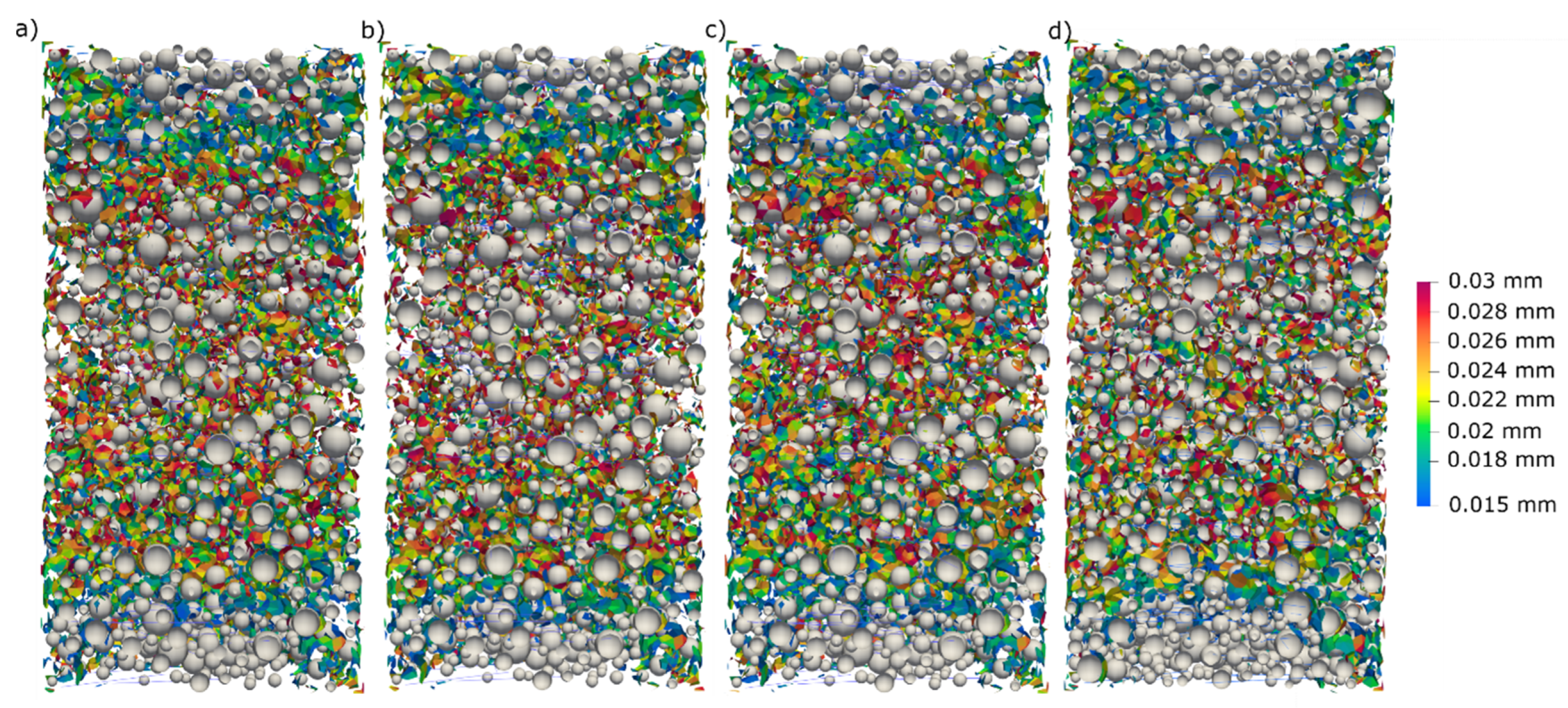
Since one of the factors affecting the energy dissipation is the crack opening effect, it was examined for different fiber contents.
Figure 4 shows the results for the investigated fiber contents.
The extracted crack data reveal that the fiber content significantly influences cracking behavior and energy dissipation. As FWR increased from 20 to 30 kg/m3, the number of cracks decreased by 6.15%, correlating with the highest observed energy dissipation at 30 kg/m3 due to effective crack bridging and distributed micro-cracking. This indicates that fibers at this level enhance ductility and resistance to crack propagation, maximizing energy dissipation. However, beyond 30 kg/m3, the number of cracks increased—by 4.81% at 40 kg/m3 and 9.51% at 60 kg/m3—suggesting that excessive fiber content leads to matrix saturation, fiber clumping, and localized stress concentrations. These factors reduce ductility and shift the failure mode from fiber pull-out to fiber breakage, diminishing energy dissipation. Thus, while moderate fiber content (30 kg/m3) optimizes energy absorption, higher fiber volumes compromise performance due to increased crack formation and reduced strain capacity.
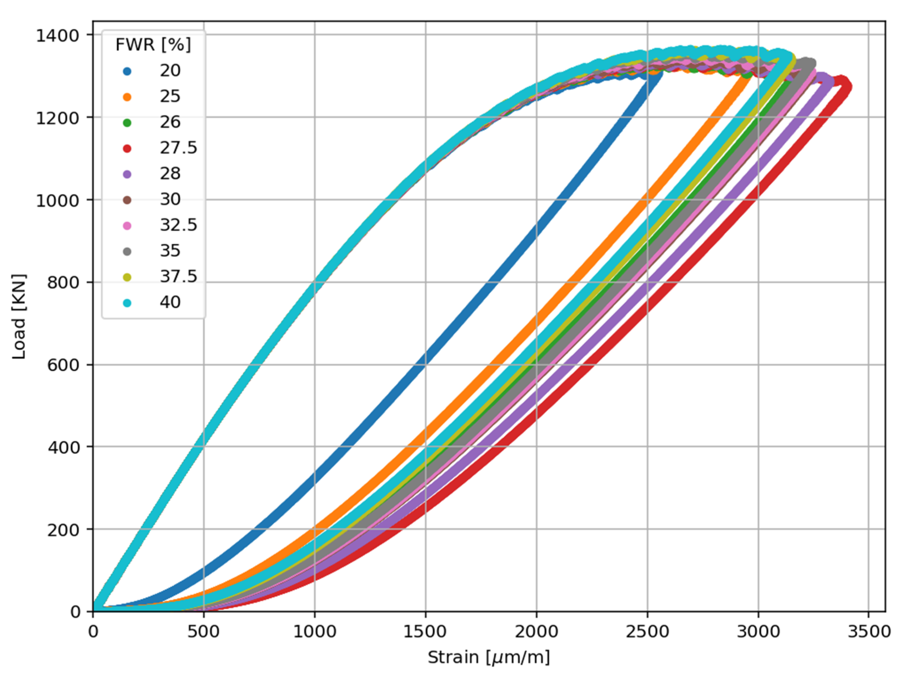
As the trend of the simulations aligned with the experimental results, the next stage in the research was to refine the determination of the optimal FWR content. With this aim, intermediate values between FWR = 20 kg/m
3 and FWR = 40 kg/m
3 were simulated, as no experimental data were available for these ranges. The simulation results are presented in
Figure 4.
Interestingly, the simulations reveal a trend that was not achieved in the experiments. It can be noticed that energy dissipation is enhanced with an increasing fiber content up to 27.5 kg/m
3 FWR and at the optimum value at this content. Energy dissipation drops above 27.5 kg/m
3 FWR, which indicates that a fiber content that is too high decreases ductility and strain capacity. As seen in
Figure 5, this result revealed through simulations over a denser range of FWR values from 20 to 40 kg/m
3 demonstrates the benefit of refining the optimization of fiber content with computational modeling.
At the next stage, it was examined how different compressive strengths affect the optimal fiber content. With this aim, the same fiber contents were used in different types of concrete with a compressive strength of 120 MPa. The simulated stress–strain curves obtained for concrete with a compressive strength of 120 MPa and FWR = 0, 20, 30, 40, and 60 kg/m
3 are shown in
Figure 6. To extend the model for 120 MPa concrete, the LDPM parameters were recalibrated accordingly. The compressive yielding strength parameter (confined) σ
C0 was adjusted to 240 MPa, while the shear-to-tensile ratio parameters were modified to σ
s/σ
t = 4.54.
The overall trend is consistent with the 90 MPa concrete results, where an FWR of 30 kg/m
3 provides the best energy dissipation performance.
Table 5 presents the changes to examine the effect of compressive strength on energy dissipation.
The compressive strength effect is seen in the slope and extent of energy dissipation change. The first fiber reinforcement from 0 to FWR = 20 kg/m3 results in a sharp relative increase (~339%) in the lower-strength 90 MPa concrete compared to the 120 MPa concrete (~188%), indicating that fibers have a greater influence on enhancing the ductility of the weaker concrete. However, while this growth occurs rapidly, the absolute magnitude of energy dissipation is higher for 120 MPa concrete at any FWR level. Specifically, the FWR = 27.5 kg/m3 is the peak point of energy dissipation for both concretes under simulation, wherein the highest peak dissipation rate is achieved at 5.87 for the 120 MPa concrete and at 1.82 for the 90 MPa concrete, demonstrating a remarkable improvement in comparison to the lower and higher contents of fibers. This comparison is an important discovery, as earlier experimental results revealed that FWR = 30 kg/m3 was the best fit. In contrast, the simulation identifies 27.5 kg/m3 as the real optimum, confirming the importance of precise fiber content optimization.
Incidentally, the asymmetry of 27.5 and 30 kg/m3 corresponds to an asymmetry between the two concrete strengths. Though the 120 MPa concrete witnesses a relatively marginal reduction (−2.7%) in energy dissipation, the 90 MPa concrete loses more energy dissipative capacity (−6%). The sharper fall in the weaker concrete indicates that the weaker concrete is more sensitive to fiber congestion, which would affect the load transfer mechanisms more detrimentally when the content of fibers is excessive. Outside this peak zone, the energy dissipation decreases further for both concretes, the decrease being quite extreme at FWR = 60 kg/m3 for 90 MPa concrete (−55%) compared to 120 MPa concrete (−36%). The observations indicate that high-strength concrete can resist the negative effect of excessive fiber content to a greater extent, with relatively better ductility and energy absorption even at high dosages of fibers. Lastly, FWR = 27.5 kg/m3 is the optimal fiber content in the simulation. This finding further indicates that lower-strength 90 MPa concrete is more prone to performance degradation when fiber content exceeds this optimum.
5. Conclusions
The influencing role of compressive strength and fiber content on the energy dissipation and ductility performance of high-strength fiber-reinforced concrete was investigated in this research using an integrated experimental and numerical approach. The results identify the optimizing role of fiber content for achieving enhanced structural performance under loading while revealing the moderating role of compressive strength on fiber effectiveness.
The numerical modeling results agreed with the test data, supporting that the fibers can enhance plastic energy capacity to be absorbed by concrete specimens. With 90 MPa and 120 MPa concrete, adding fibers brought large amounts of increased energy absorption compared to normal concrete. However, the relationship between fiber weight ratio (FWR) and energy dissipation was non-linear, emphasizing the importance of identifying an optimal fiber content.
The previous experimental measurements had shown FWR = 30 kg/m3 to be the optimum. However, the sophisticated simulations showed a refined optimum at FWR = 27.5 kg/m3 for both concrete types. This finding emphasizes the need for numerical modeling in optimizing a material quantity within tighter incremental ranges than experimentation permits. At the optimized FWR value of 27.5 kg/m3, the maximum simulated energy absorption achieved was 5.87 kNm/m for 120 MPa concrete and 1.82 kNm/m for 90 MPa concrete.
The compressive strength effect was expressed in the rate and extent of change in energy dissipation. The initial fiber addition from 0 to 20 kg/m3 produced a more significant relative increase (~339%) in the 90 MPa concrete than in the 120 MPa concrete (~188%), suggesting that fibers are more important in increasing the ductility of lower-strength concrete. Despite that, all the total energy dissipation values were greater in 120 MPa concrete at each FWR level.
Beyond the limiting FWR of 27.5 kg/m3, energy dissipation decreased for both concretes. The reduction was higher in the lower-strength 90 MPa concrete, particularly at FWR = 60 kg/m3 (−55%), compared to the 120 MPa concrete (−36%). This difference suggests that lower-strength concrete is more susceptible to fiber content, which can degrade load transfer mechanisms and compromise ductility.
Further, the transition from FWR = 27.5 kg/m3 to 30 kg/m3 reflected an asymmetric drop in the two concrete strengths. While the 120 MPa concrete showed a marginal drop in energy dissipation (−2.7%), the 90 MPa concrete exhibited a more significant fall (−6%). This bifurcation indicates the vulnerability of weaker concrete to high fiber content, which will worsen issues like matrix saturation, fiber clumping, and localized stress concentrations. Beyond the critical FWR of 27.5 kg/m3, the energy dissipation decreased in both concretes. This means that lower-strength concrete is more vulnerable to over-content of fibers since an excess of fibers tends to disrupt the matrix and weaken the load transfer, which ultimately decreases ductility. On the other hand, higher-strength concrete possesses a greater tolerance for the increment of fiber dosage but still experiences decreasing energy dissipation beyond the optimum content, suggesting the need for an optimized strategy of fiber selection.
The current research generally points to proper fiber content optimization for achieving optimal energy dissipation in high-strength FRC. Moderate fiber content enhances ductility and energy absorption, whereas a high content of fibers results in performance loss, particularly with lower-strength concrete. The increased resistance of 120 MPa concrete to high fiber content reflects the interaction between compressive strength and fiber reinforcement efficiency. Lastly, the specification of FWR = 27.5 kg/m3 as the optimum fiber content is of practical value in the design and performance optimization of high-strength FRC for structural applications. The selection of an appropriate fiber content should consider whether the primary goal is for maximum strength, crack control, or energy dissipation. Our analysis found the optimum dosage of 27.5 kg/m3 to be based on the maximization of energy dissipation. While design guidelines in practical engineering would rather have higher fiber contents for better peak load strength, this present study points out the necessity of the correct choice of fiber dosages appropriate to the structural need, particularly in those cases where enhanced ductility and energy absorption are necessary; e.g., seismic-resistant design.


