Article

Qualitative Analysis of Sleeper Supporting Condition for Railway Ballasted Tracks Using Modal Test

1
Department of Construction Engineering, Dongyang University, No. 145 Dongyangdae-ro, Punggi-eup, Yeongju-si 36040, Republic of Korea
2
Seoul Metropolitan Regional Office, Korea National Railway, No. 378, Cheongpa-ro, Yongsan-gu, Seoul 04301, Republic of Korea
3
Department of Architectural Engineering, Gachon University, Seongnam-si 13120, Republic of Korea
*
Author to whom correspondence should be addressed.
Appl. Sci. 2025, 15(7), 3425; https://doi.org/10.3390/app15073425
Submission received: 25 February 2025 / Revised: 15 March 2025 / Accepted: 19 March 2025 / Published: 21 March 2025

Abstract

:
During railway operations, changes in the support conditions of sleepers, owing to various internal and external factors, can damage rails and concrete sleepers and alter the structural characteristics of gravel-ballasted tracks. However, current methods for evaluating gravel ballast conditions primarily rely on visual inspection. This study proposes a quantitative approach using modal testing to assess ballast conditions. This is achieved by analyzing and experimentally verifying the relationship between track ballast loosening (caused by subgrade deformation) and track support performance. Finite element analysis results and field experimental values were compared using spring stiffness as a parameter. The results showed that natural frequencies and mode shapes changed in response to variations in the vertical spring stiffness of the gravel-ballasted track. Therefore, the sleeper support condition of a gravel-ballasted track can be readily identified by analyzing the natural frequency corresponding to different sleeper support conditions.

1. Introduction

In recent years, urban expansion near South Korea’s city centers, including the construction of new buildings and enlargement of utility conduits, has caused deformation in railway structures, necessitating frequent repair and reinforcement. However, while these efforts have primarily focused on structural inspection and reinforcement, the railway tracks themselves have often been overlooked. Concrete tracks, with their higher stiffness, are generally less susceptible to deformation from external influences than gravel-ballasted tracks. Moreover, gravel-ballasted tracks lack rigid integration with the subgrade and ballast, making them particularly vulnerable to even minor subgrade deformations, which can cause the ballast to loosen. Additionally, a repeated load of the train leads to a void between the sleeper and ballast. Floating sleepers cause track settlement and deterioration. It is difficult to quantitatively examine floating sleepers. Therefore, the maintenance of floating sleepers is important [1].
To enhance the safety of railway structures, track settlement systems were deployed to monitor deformations in real time. Nevertheless, current methods fall short in evaluating the condition of the ballast beneath the sleepers, a critical factor affecting the support performance of gravel ballast tracks.
Various researchers have contributed to understanding the dynamic changes associated with damage to concrete sleepers. Choi et al. [2] applied modal testing techniques and impact hammer tests to study the dynamic characteristics of concrete sleepers. Remennikov and Kaewunruen [3] explored how boundary conditions affect the vibration characteristics of these sleepers, whereas Kaewunruen [4] examined the influence of changes in material properties and rail pad stiffness on the free vibration characteristics of in situ concrete sleepers. Kim and Jung [5] employed impact hammer tests to assess the structural integrity of aging railway plate bridges and validated the reliability of these field tests through full-scale experimental modal analysis. Furthermore, Kaewunruen and Remennikov compared the outcomes of non-destructive impact hammer testing with those of visual inspections [6], whereas Ferdous et al. and Kaewunruen et al. investigated the potential damage to concrete sleepers [7,8]. Silva et al. determined, based on indoor testing and numerical analysis, that the primary type of damage to prestressed sleepers typically occurs directly beneath the rail [9]. Tatarinov et al. attributed sleeper damage to dynamic loads from train operations and exposure to climatic variations [10]. Choi et al. [11] and Shin [12] investigated damage types in concrete sleepers situated on the sharp curves of operational tracks, exploring how gravel replacement and sleeper renewal could mitigate this damage. Their findings indicated that axial cracks are prevalent, and improvements to the track structure significantly enhance load distribution, thereby reducing stress on the sleepers. Park and Chung et al. employed numerical simulations to model gravel ballast and analyze track irregularities and the forces of wheel–rail interactions resulting from excavation activities on operational gravel-ballasted tracks [13,14].
Sysys et al. [15] conducted both theoretical and experimental studies on sleeper support conditions using a mechanical model integrated with a data-driven approach. Their findings demonstrated that recent air gaps could be accurately identified by extracting wavelet scattering features from trackside measurements using machine learning techniques. Zakeri et al. [16] examined the effect of sleeper support modulus on the dynamic behavior of railway tracks caused by moving wagons, employing both numerical simulations and field tests. Their results indicated a strong agreement between the numerical analysis and field measurements. Similarly, Esmaeili et al. [17] investigated the dynamic properties of railway ballast mixed with tire-derived aggregates using modal shaker tests. Their findings revealed that an increase in the proportion of tire-derived aggregates in the ballast mixture led to a significant reduction in subgrade stiffness and a corresponding increase in the damping ratio. Liu et al. [18] assessed the vertical vibration and transmission characteristics of railway ballast using impact hammer tests, demonstrating that as depth increased, both the vertical vibration transmission rate and accumulated external force gradually decreased. Feng et al. [19] compared the dynamic response of a ballasted track obtained from discrete element modeling with results from dynamic load tests. Khan and Dasaka [20] performed numerical analysis to quantitatively assess vibrations induced by high-speed trains on ballasted railway tracks. Their study estimated high vibration magnitudes on railway embankments and the ground, particularly when the effects of multiple train wheels were superimposed.
Benedetto et al. [21] proposed a method for assessing the condition of railway tracks using GPR. The experimental results were verified through simulations based on RSA-FDTD. Li et al. [22] reviewed a geometric deterioration prediction model for railway tracks using machine learning and compared and analyzed existing prediction methods. As a result, the machine learning-based method provided high prediction accuracy. However, it showed limitations such as lack of interpretability and difficulty in parameter adjustment, suggesting the need for further research. Wang et al. [23] analyzed the effects of fouling and degradation on the shear strength of the roadbed. As a result, the penetration of fine particles and degradation decreased the shear strength of the roadbed. Lam and Wong [24] utilized impact hammer tests to monitor sleeper vibrations for detecting ballast damage. Their results indicated that ballast degradation led to a reduction in the stiffness supporting the sleeper, altering its vibration characteristics. Additionally, Kim et al. conducted modal tests on various railway track types to analyze the dynamic characteristics of railway bridges. Their findings showed that, despite relatively low experimental excitation loads, damping ratios ranging from 1.0% to 2.0% were consistently observed in most cases [25].
Previous studies have largely focused on the deformation and dynamic characteristics of gravel ballast without accurate track modeling, and they often have not confirmed the precision of the numerical models or the results with comprehensive measurement data.
Although research using modal testing to assess concrete sleeper damage has been widely conducted internationally, in South Korea, such damage is predominantly evaluated via visual inspections. This study modeled the rail and the concrete sleeper as three-dimensional elements and configured a spring element, using the spring stiffness of the ballast as a variable, to represent the support condition of the sleeper. Additionally, the natural frequencies measured through modal tests and the analyzed values were compared to validate the numerical analysis modeling and results.

2. Materials and Methods
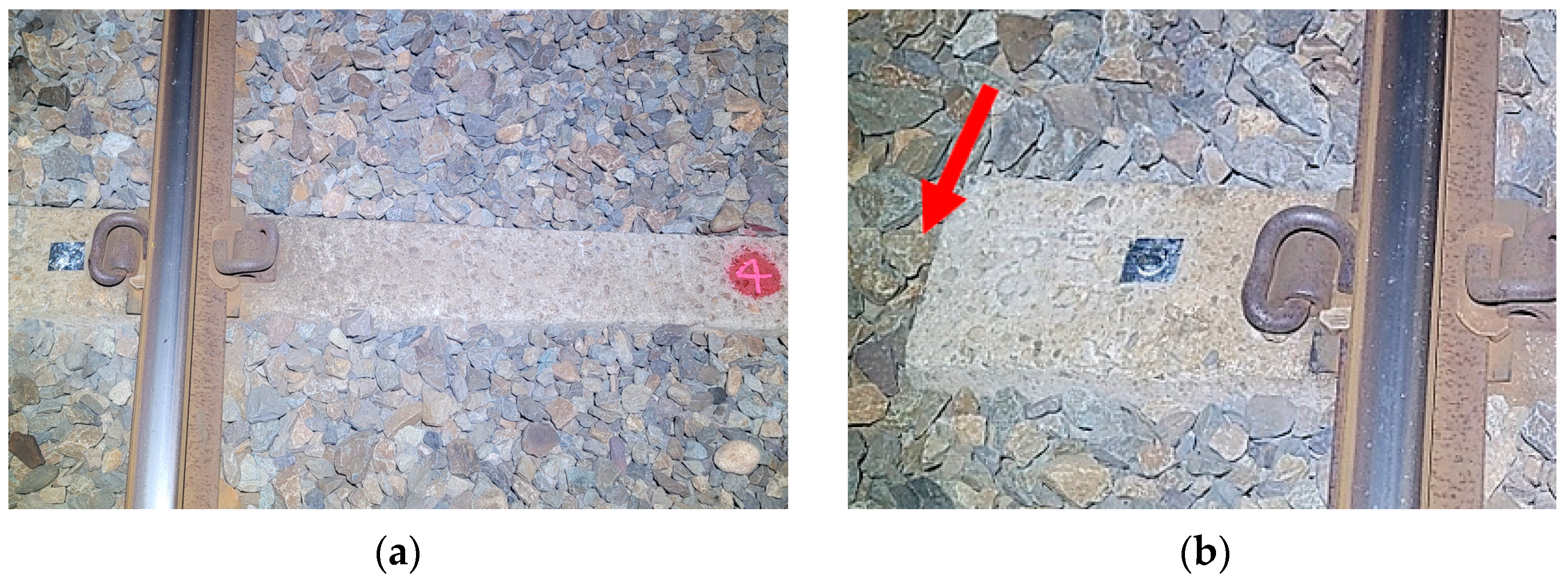
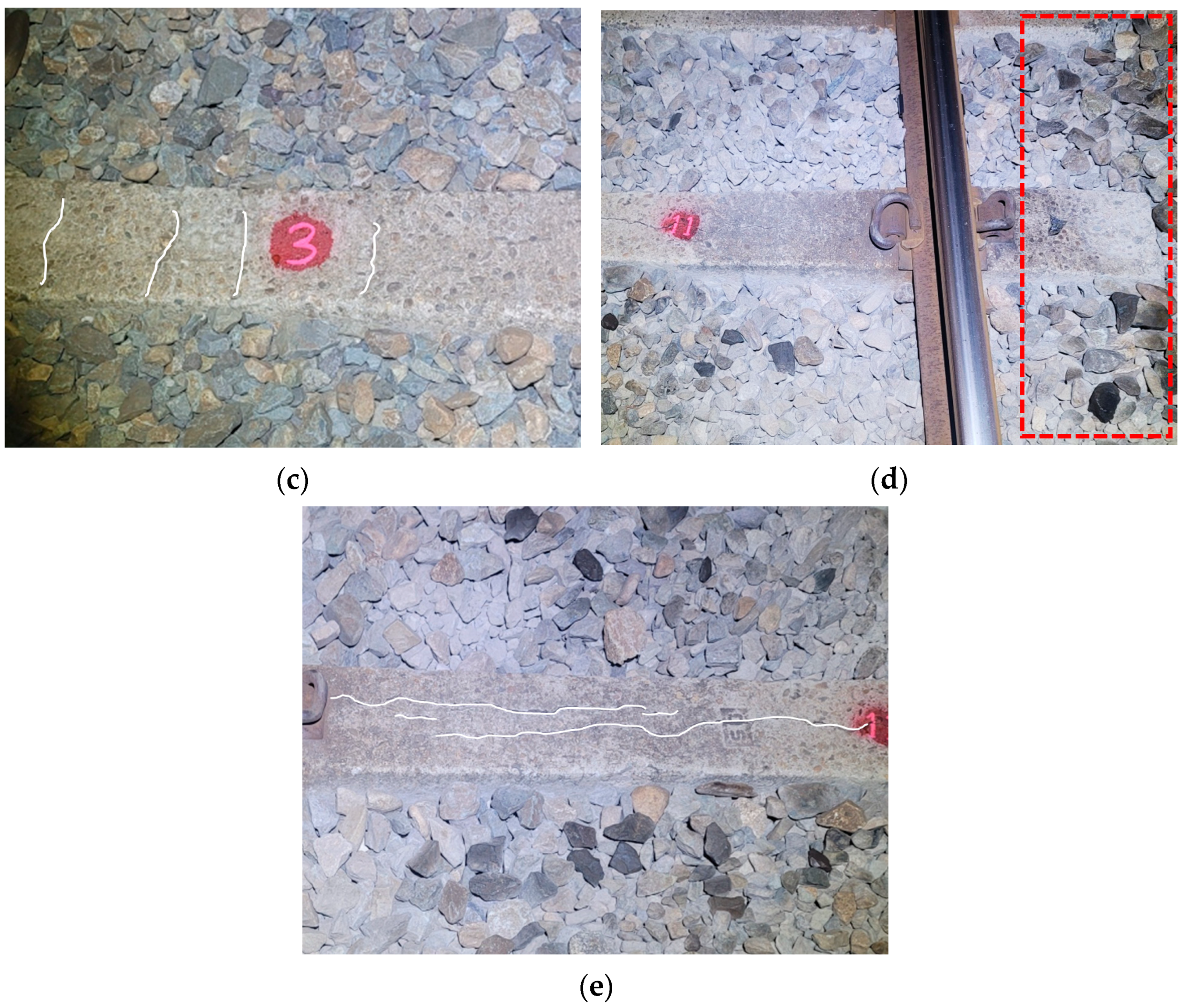
2.1. Materials

Track deformation was measured to examine the deformation of gravel ballast and the changes in sleeper support conditions because of adjacent excavation work. Additionally, sections of the gravel ballast track exhibiting both poor and good sleeper conditions prior to the excavation were examined.
For modal testing, 24 sleepers on both the up and down tracks were examined, focusing on key locations during the stages of adjacent excavation work. The sleeper length is 2400 mm and the ballast layer thickness is 300 mm. The track on which the field experiment was conducted is a railway track used by urban trains. On average, approximately 170 trains pass through the track daily, traveling at an average speed of 70 km/h. Examples of the examined sleepers are shown in Figure 1.

2.2. Dynamic Characteristic Analysis of Track Using Modal Testing

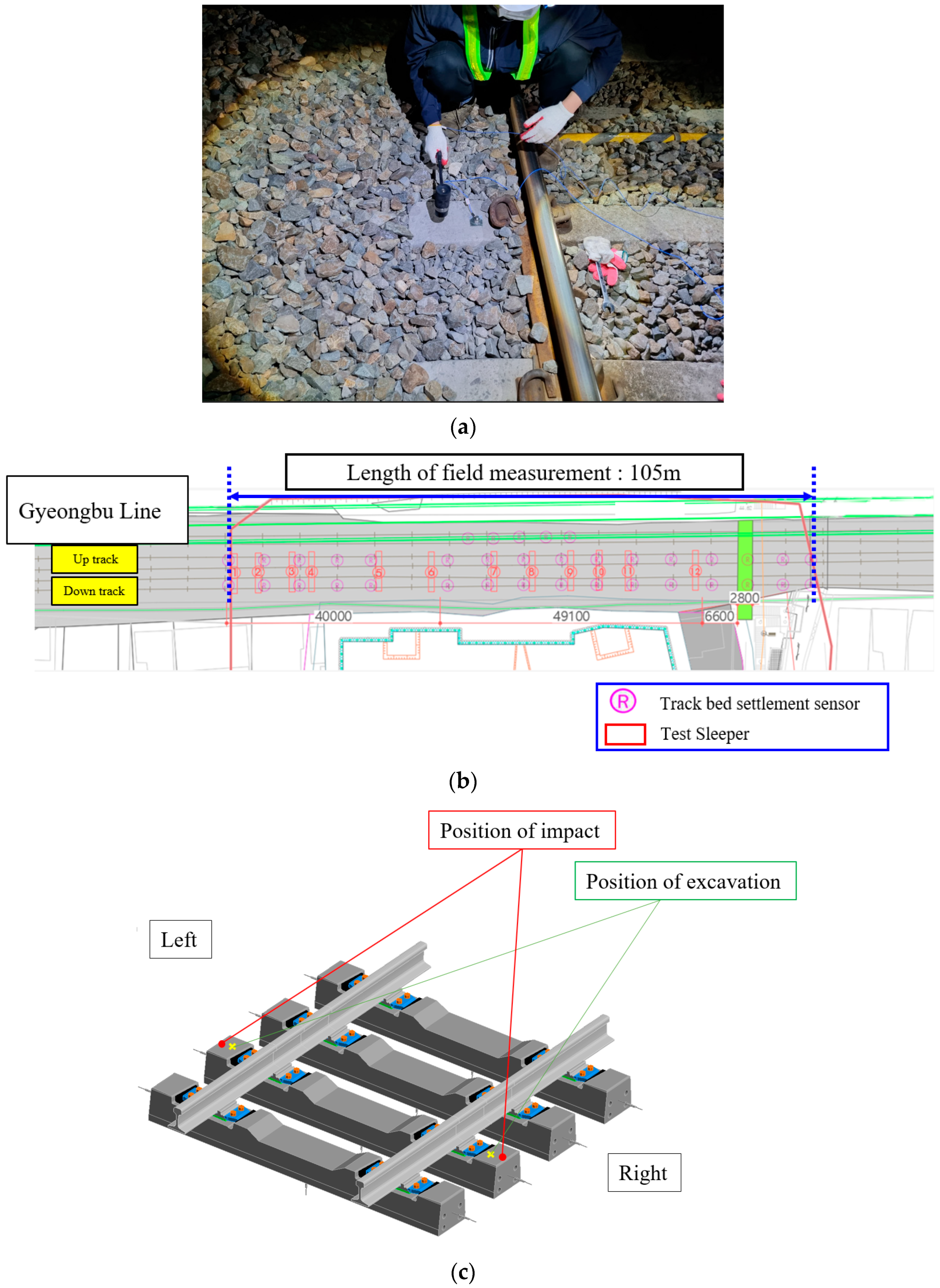
2.2.1. Testing Method
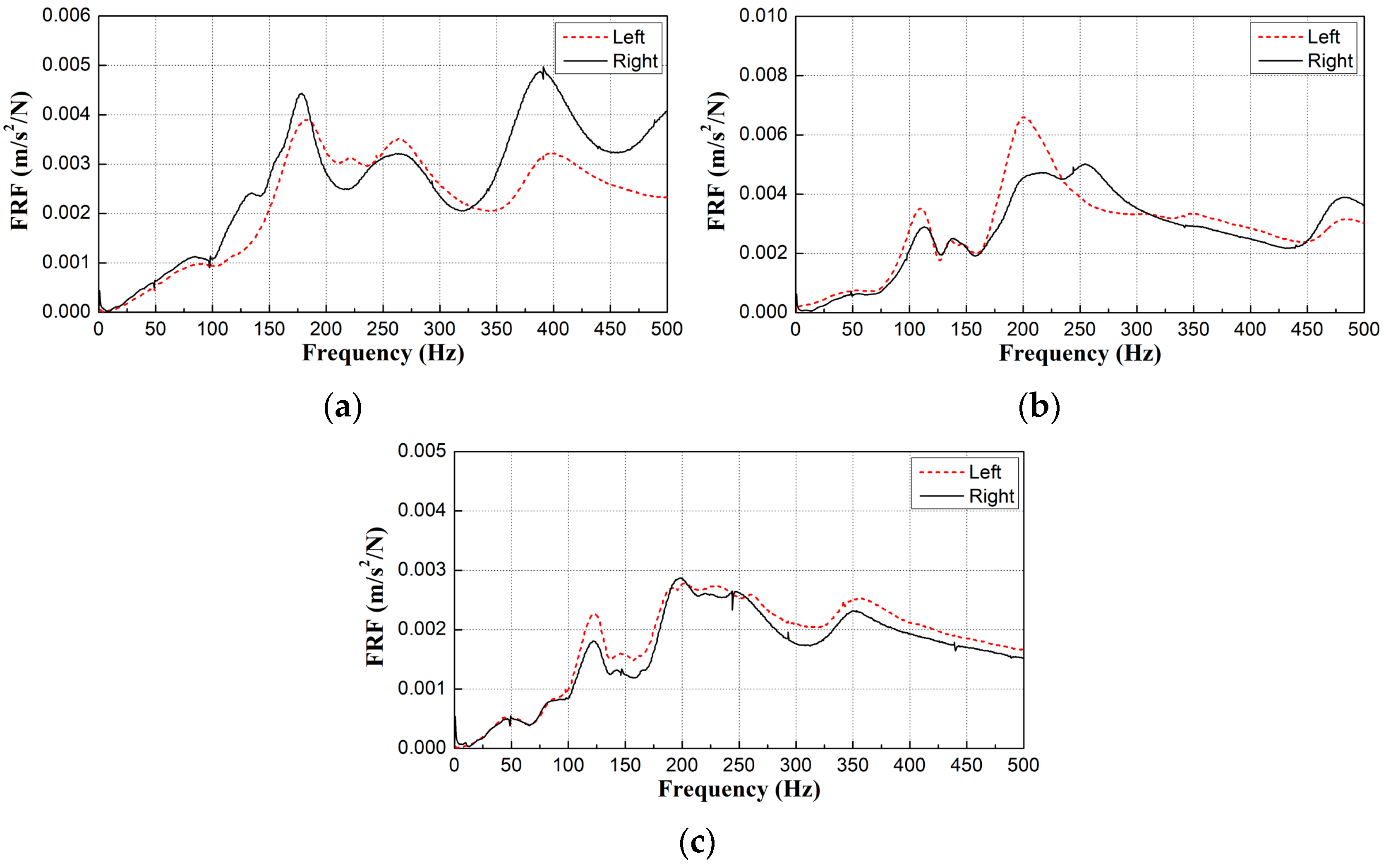
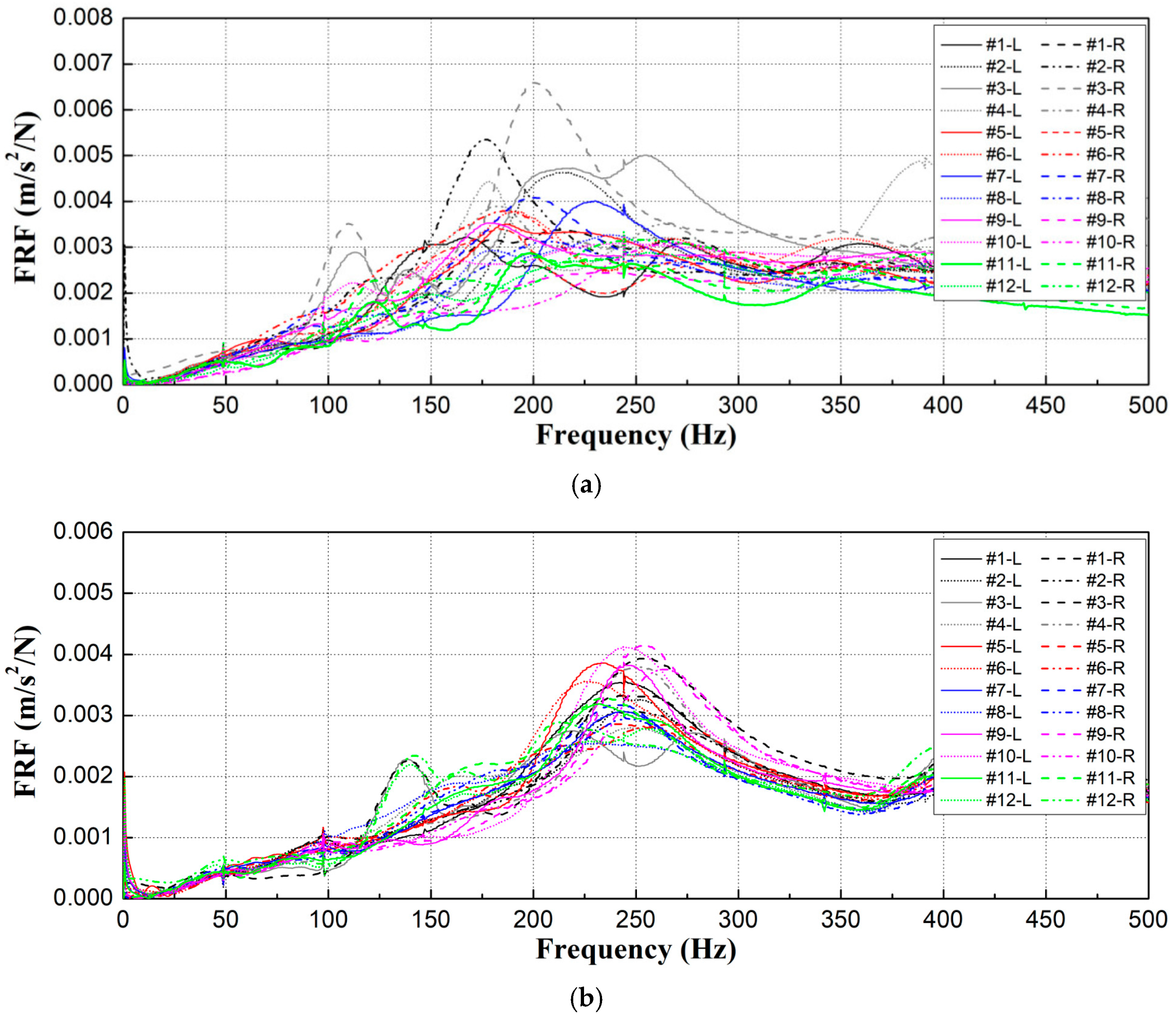
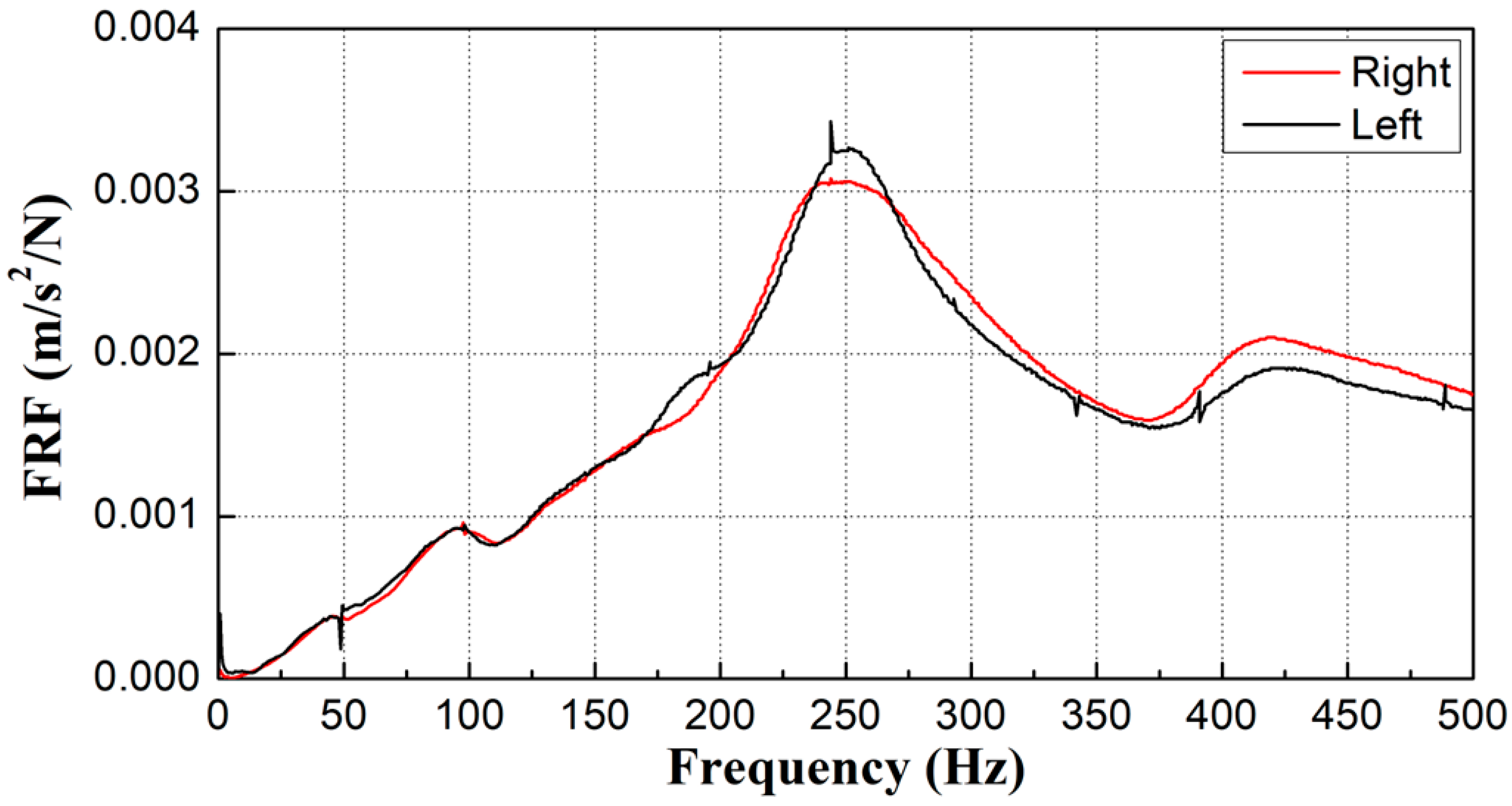
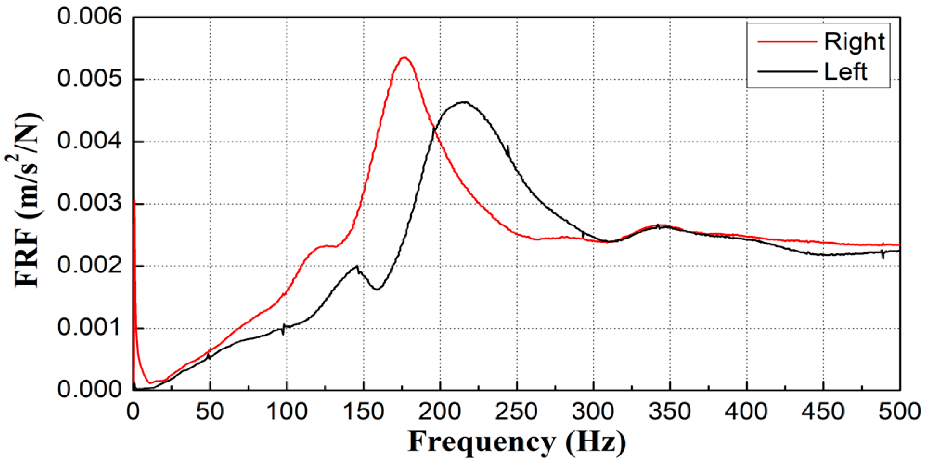
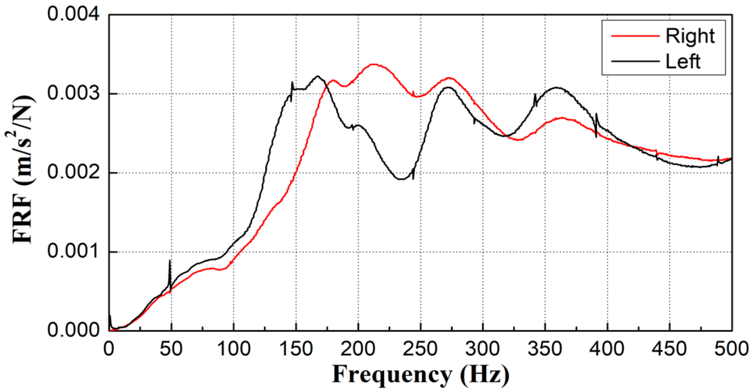
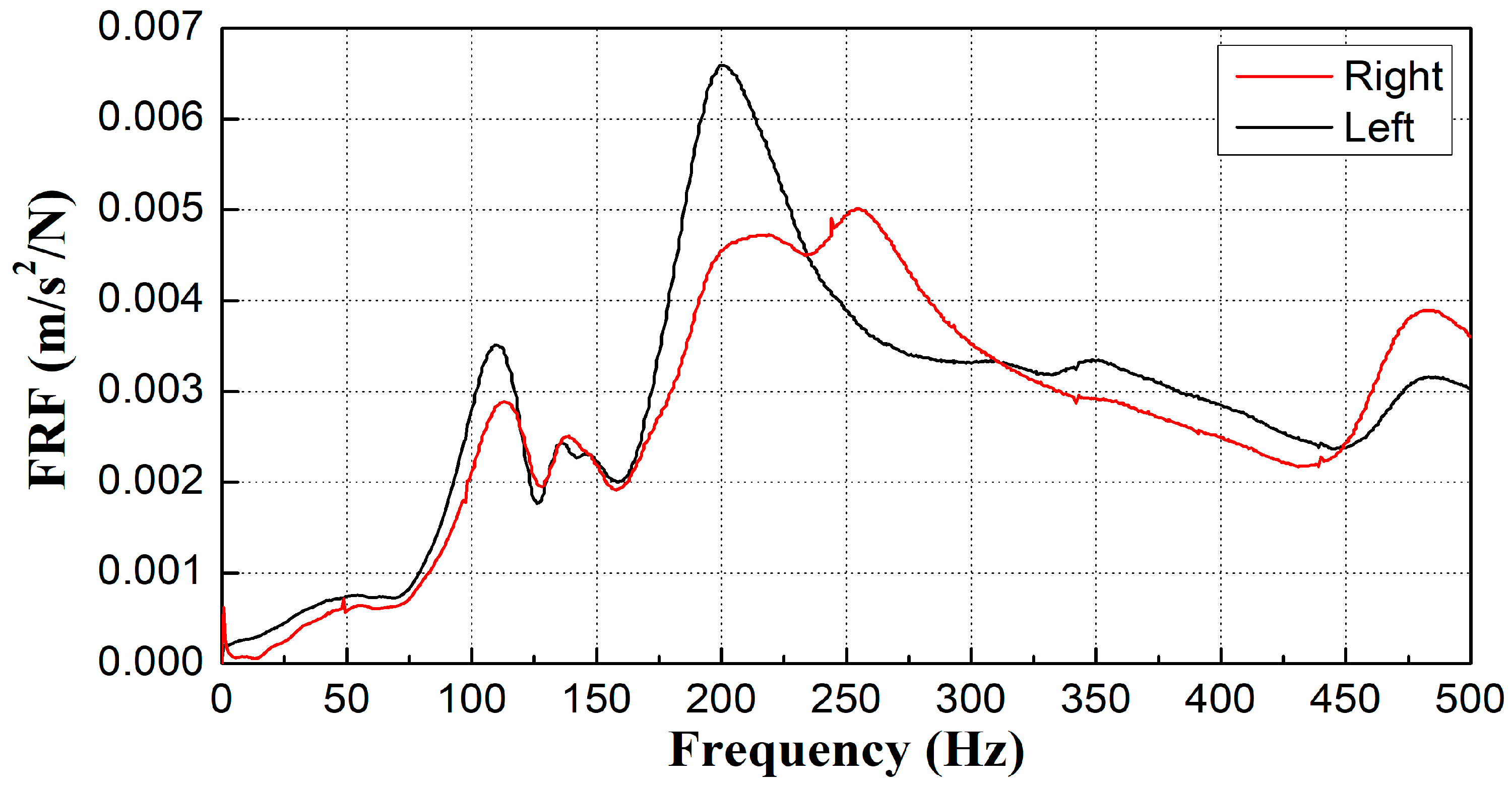
The modal testing technique was used to obtain frequency response functions (FRFs) for calculating the natural frequencies of the concrete sleepers on the gravel track. Table 1 shows the sensitivities of the sensors in the measurement system.
Accelerometers (PCB piezotronics, Depew, NY, USA) were installed on the top surface of the concrete sleepers to measure the acceleration resulting from the impact hammer (PCB piezotronics, Depew, NY, USA) strikes. Figure 2a shows an overview of the field measurements for the modal test, with the modal test measurement locations on the left and right sides of the concrete sleeper. Figure 2b is a schematic diagram of the sensor measurement location. Figure 2c provides details of the measurement locations.

2.2.2. Test Results

Modal testing was conducted on the gravel ballast of the operational tracks, and the FRFs and natural frequencies were measured, as shown in Figure 3. The first natural frequencies were calculated from the FRFs and are summarized in Table 2.
According to the natural frequency analysis, as shown in Figure 3a, the left and right natural frequencies of sleeper #4 were similar, and poor gravel compaction was not observed during the visual inspection. However, as shown in Figure 3b,c, the natural frequencies were more than 50 Hz lower than those of sleeper #4. The visual inspection revealed poor gravel compaction and cracks in the sleepers, which reduced the spring stiffness of the ballast beneath them, resulting in relatively lower natural frequencies. Therefore, in gravel-ballasted tracks, changes in sleeper support conditions, such as sleeper damage, floating sleepers, and poor gravel compaction, can directly affect the natural frequencies.
Figure 4 depicts the analysis of the FRFs for all concrete sleepers on both the up and down tracks prior to construction. Specifically, as shown in Figure 4a, the first mode frequency ranged between 100 and 125 Hz on the up track near the excavation site, and many first modes were distributed between 150 and 200 Hz. For the down track, which was farther from the excavation site, the first mode occurred at 125–150 Hz for some sleepers, whereas for most sleepers, it ranged between 200 and 250 Hz, as illustrated in Figure 4b.
The analysis prior to construction indicated that the up track experienced reduced stiffness, attributable to floating sleepers and poor gravel compaction. Conversely, although some sleepers exhibited floating or reduced stiffness on the down track, most maintained normal first natural frequencies.

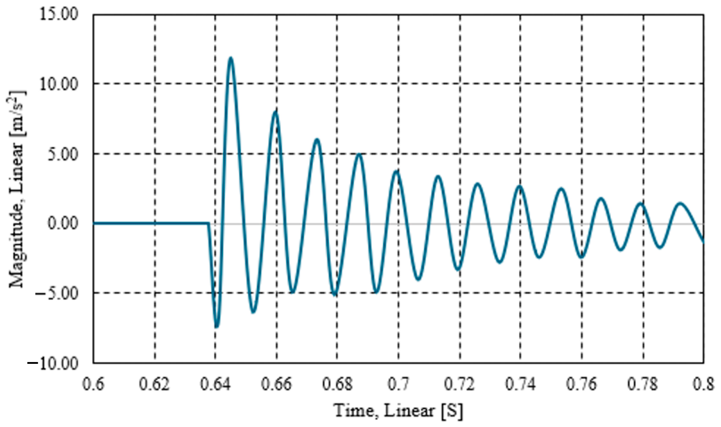
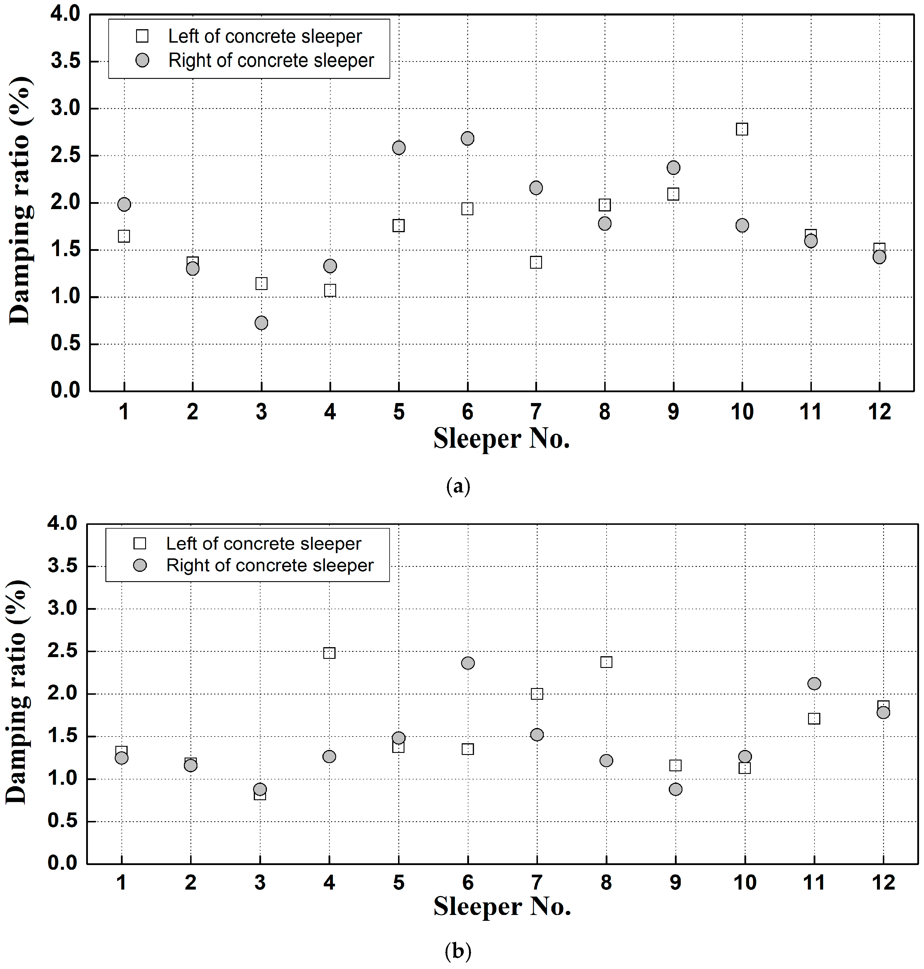
2.3. Damping Ratio Analysis

Regarding structural damping, where amplitude decreases over time, the damping ratio in the free vibration region can be calculated using Equation (1) [26].
δ = l n u 1 u 2 = 2 π ξ 1 ξ 2 2 π ξ ,
where δ denotes the logarithmic decrement, representing the ratio of amplitude decrease after one cycle ( T d ) of free vibration.
Equation (2) presents the formula for estimating the damping ratio [26], and an illustrative example is provided in Figure 5.
δ = 1 n l n u 1 u n + 1 = 2 π ξ 1 1 ξ 2 2 π ξ ,
The pre-construction damping ratio analysis results are shown in Figure 6.
According to this analysis, as displayed in Figure 6a, the damping ratio for sleeper #3 on the up track was less than 1%. However, most concrete sleepers exhibited a damping ratio of approximately 2%. Figure 6b indicates that on the down track, sleepers #3 and #9 had damping ratios below 1%, whereas most had damping ratios ranging from 1% to 1.5%.

3. Natural Frequency Analysis of Ballasted Track Sleepers
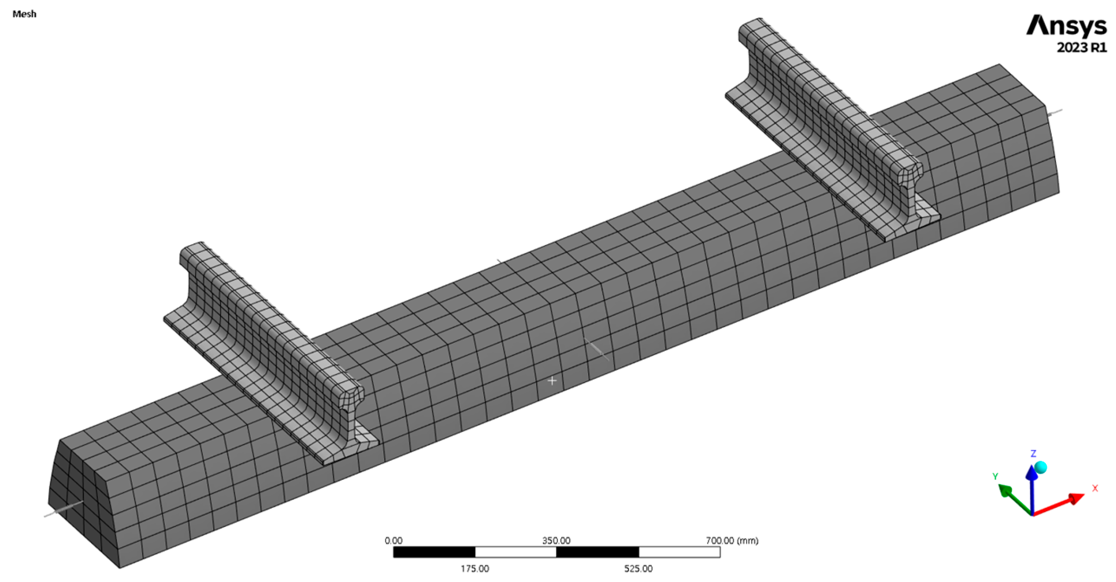
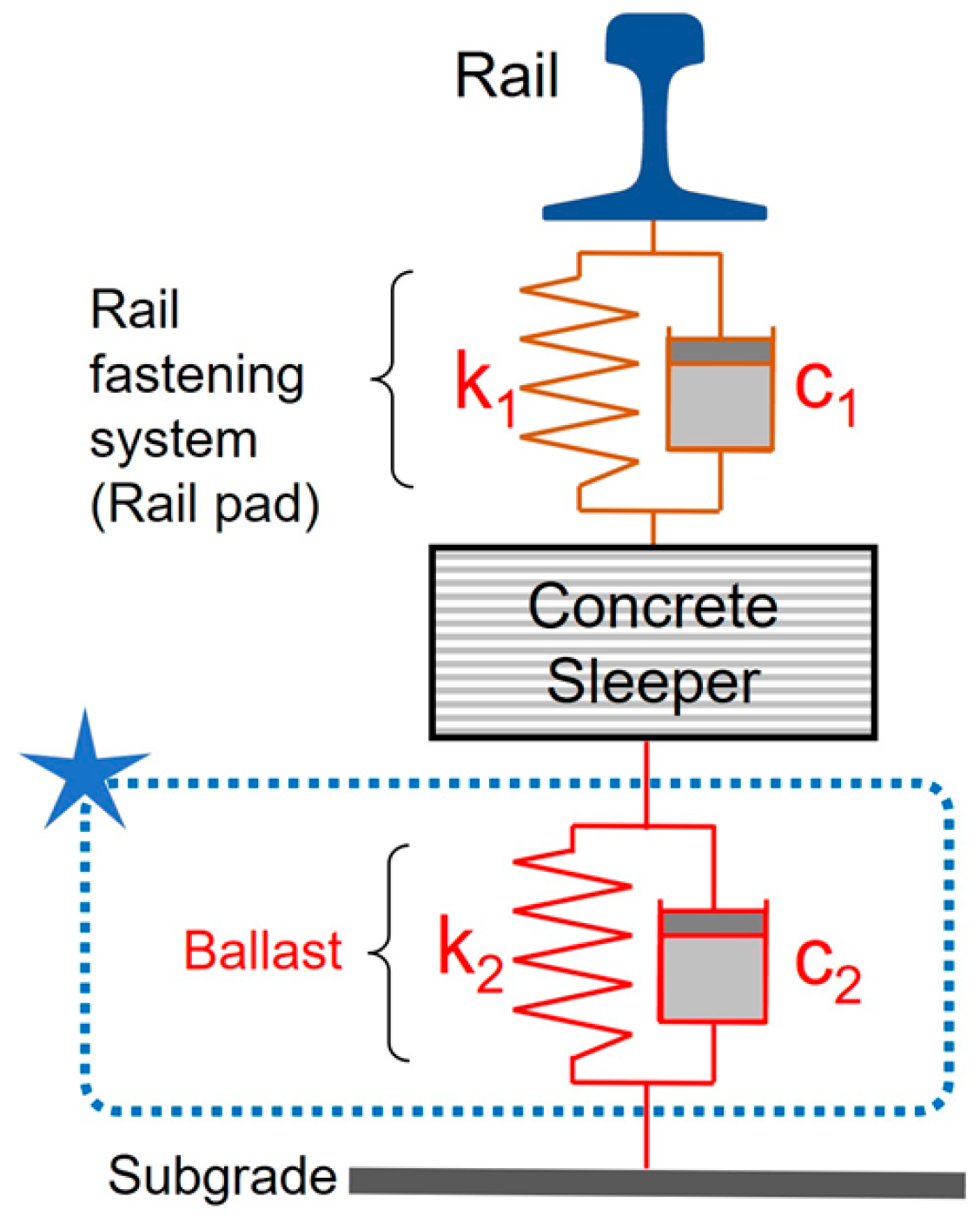
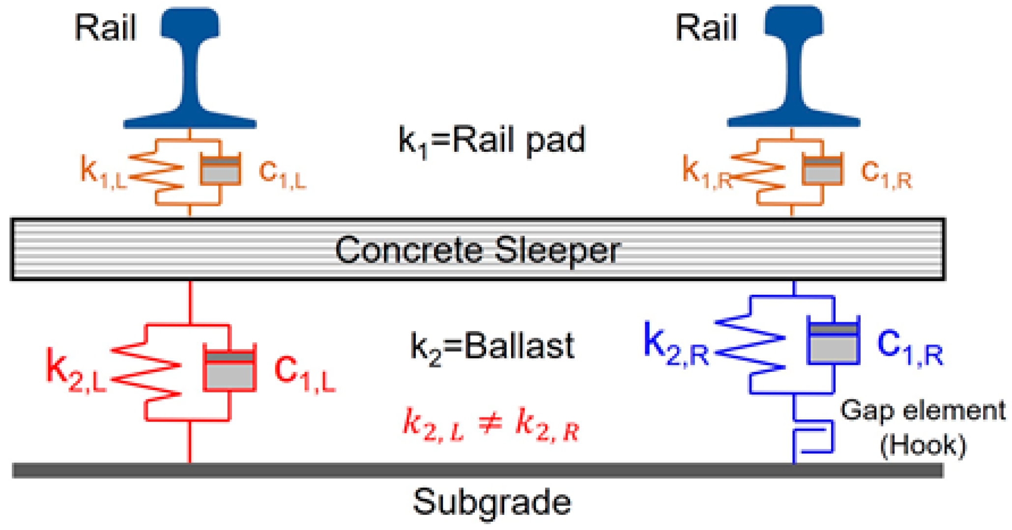
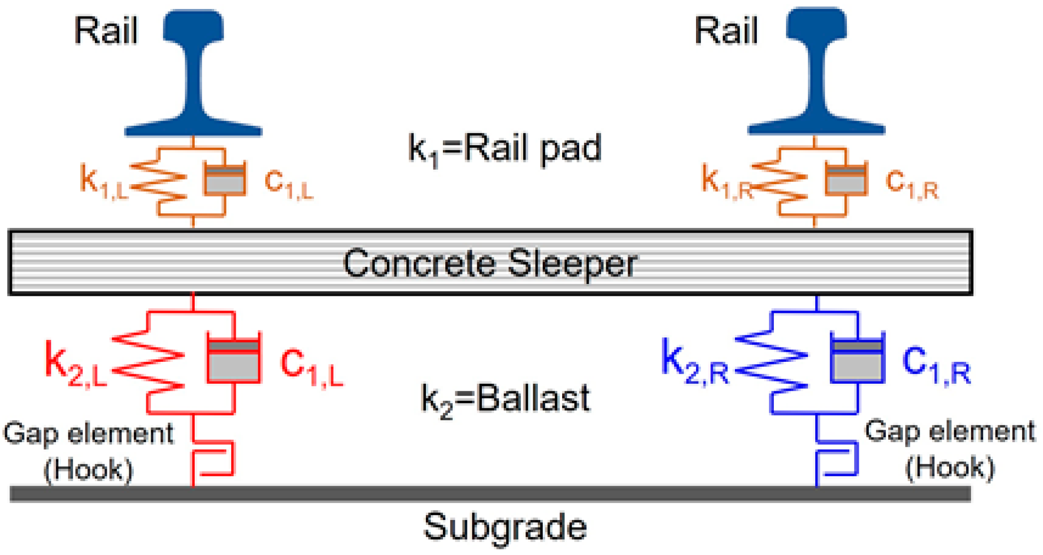
3.1. Modeling

The structural analysis program Ansys Workbench Ver. 2023R1 was employed to analyze the natural frequencies of the track gauge, which are influenced by changes in the spring stiffness of the ballast beneath the sleepers [27]. The numerical analysis model is depicted in Figure 7, and the specifications used in the analysis are detailed in Table 3. In Figure 7, the length of the modeled rail is set to 625 mm, corresponding to the rail support spacing. The dimensions of the sleeper are width × height × length: (180 mm (top) − 280 mm (bottom)) × 200 mm × 2400 mm. As shown in Figure 8, the model incorporated spring elements to represent the gravel ballast and rail pads of the gravel-ballasted track.
According to KR C-14030 [28], the spring stiffness was set to 650 kN/mm for the rail pad and 200 kN/mm for well-compacted ballast. The loading conditions for the numerical analysis, detailed in Figure 9, included a force of 7000 N applied at the same points impacted by the modal test hammer in field tests. For vertical spring, the rail pad connects the lower rail and the upper part of the sleeper (body-to-body). The ballast sets the lower part of the sleeper and the ground (body-to-ground) as elastic support. The boundary condition is lower part of the rail end section as a fixed support.

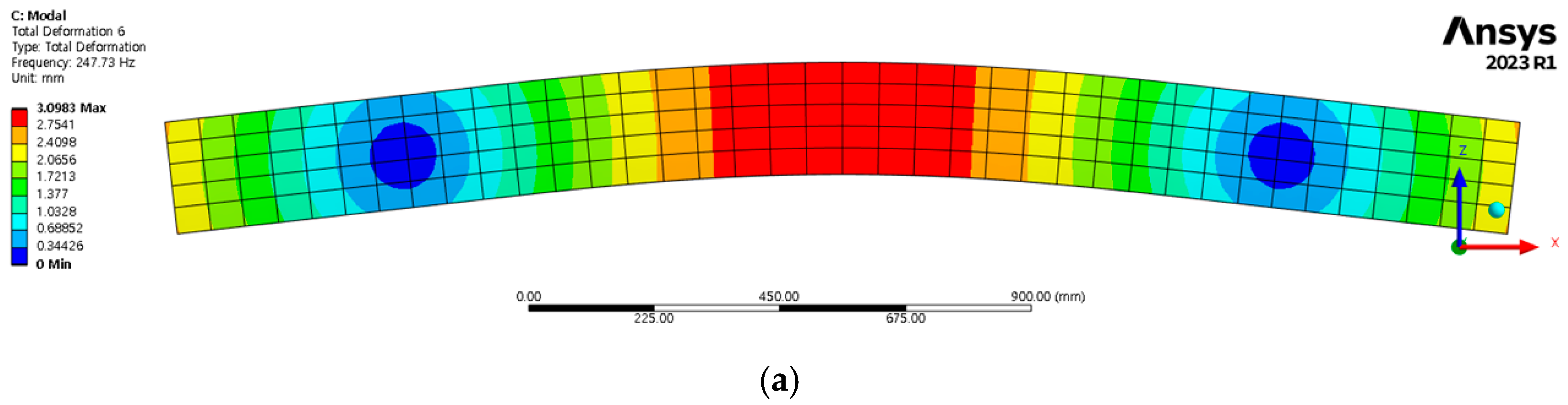
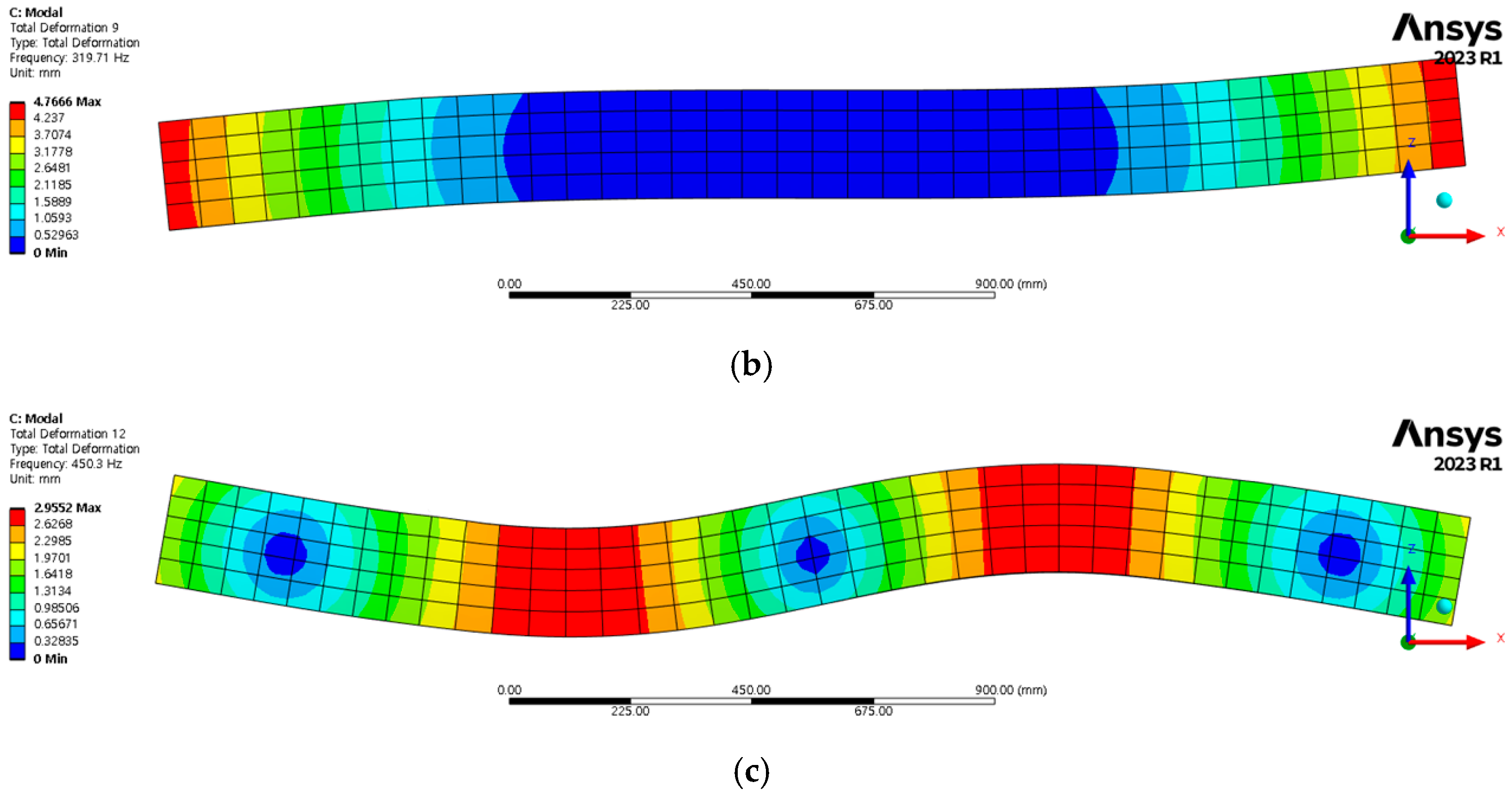
3.2. Numerical Analysis Results

3.2.1. Natural Frequency of Sleepers in Normal Gravel Ballast Conditions

Finite element analysis was employed to verify the FRFs at the same location as the modal test, using the field measurement results from normal gravel ballast conditions. The results are shown in Figure 10.
The numerical analysis results indicate that setting the spring stiffness of the gravel ballast to 200 kN/mm resulted in a first natural frequency of approximately 247.73 Hz. This indicated a deviation of approximately 0.91% from the field-measured natural frequency of approximately 250 Hz for sleepers in good condition, demonstrating that the analysis model adequately reflects actual track conditions.
Additionally, the mode shapes of the gravel-ballasted sleepers were examined. The results for the first, second, and third bending modes under normal conditions are presented in Figure 11.
Analysis of the bending mode shapes of the gravel-ballasted sleepers under normal conditions indicated that the largest bending deformation occurred in the center of the sleeper at the first natural frequency of 247.73 Hz, as shown in Figure 11a. In the first mode, deformation was initiated directly beneath the rails on both sides. In contrast, the largest deformation at the second natural frequency of 319.71 Hz occurred on the outer part of the sleeper, as shown in Figure 11b. Additionally, at the third natural frequency of 450.3 Hz, significant deformations occurred between the center of the sleeper and directly beneath the rails on both sides, as depicted in Figure 11c.

3.2.2. Natural Frequency Based on Changes in Spring Stiffness

Natural frequencies were analyzed according to changes in the vertical spring stiffness of the gravel ballast, with the spring stiffness set to vary from 200 to 0.1 kN/mm. According to the KR C-14010 [29], the stiffness of a normal sleeper should be 200 kN/mm; therefore, the spring stiffness was used as a variable to represent the reduced stiffness of a damaged sleeper. The mode shapes were also analyzed based on the changes in the spring stiffness of the ballast. As the spring stiffness decreased, changes in the first bending mode shape were observed, as shown in Figure 12.
Specifically, with a spring stiffness of 50 kN/mm, an upward bending deformation occurred at the center of the sleeper, as highlighted in Figure 12a. When the spring stiffness was further reduced to 40 kN/mm, a downward bending deformation emerged at the center, as shown in Figure 12b.
The results of the natural frequency analysis, based on variations in ballast spring stiffness, are presented in Figure 13.
Under a spring stiffness of 200 kN/mm, the natural frequency was approximately 247.73 Hz. When this stiffness was halved to 100 kN/mm, the natural frequency decreased to approximately 198.82 Hz. Furthermore, a drastic reduction in spring stiffness by 90% to 10 kN/mm resulted in a natural frequency of 136.39 Hz.

4. Analysis and Discussion

4.1. Analysis of Natural Frequency Characteristics by Type of Sleeper Support Condition

This study analyzed the natural frequencies according to the left and right under-sleeper support conditions using the FRFs measured in the field via modal testing, as shown in Figure 14. The measurement results are shown in Figure 15.
Under normal conditions, as demonstrated in Figure 15, the first natural frequencies on both sides of the frequency response function were similar at approximately 250 Hz, which aligns with the expected values under normal support conditions. This similarity indicates that the under-sleeper support on both sides was functioning properly.
Furthermore, this study investigated instances where track settlement occurred, owing to subgrade deformation from adjacent excavation activities, resulting in compromised support conditions, as shown in Figure 16. In the case of poor support conditions on the lower side of the concrete sleeper, such as floating sleepers or gravel loosening, these conditions can be represented by a gap element, as shown in Figure 16. Owing to the gap element, the stiffness of the left and right sleepers is not the same ( k 2 , L k 2 , R ). The ballast spring stiffnesses on the left and right may differ, which indicates that a certain level of sleeper displacement must occur—as in the case of floating sleepers or gravel loosening—for the ballast to perform its role as a spring. The measurement results for concrete sleepers under such conditions are shown in Figure 17.
In the case of poor under-sleeper support on the right side, as shown in Figure 17, the first natural frequency on the right side of the FRF was smaller than that on the left.
The measurement results for poor under-sleeper support on the left side, shown in Figure 18, indicate a lower first natural frequency on the left side of the FRF than that on the right, confirming that sleeper support conditions, qualitatively evaluated via visual inspection, can be quantitatively assessed by analyzing the differences in the first natural frequency through modal testing.
When under-sleeper support conditions on both sides of the concrete sleeper were poor, with gravel loosening occurring on both sides, gap elements occurred on both the left and right lower sides of the sleeper, as shown in Figure 19. When gravel loosening occurs on a gravel-ballasted track, a certain level of sleeper displacement must occur for the track gravel to function as a spring.
In cases where both the left and right under-sleeper supports were poor, as shown in Figure 20, the first natural frequencies on both sides of the FRF were similar. However, the first natural frequencies were significantly lower than those in normal support conditions, suggesting that both sides of the sleeper may be floating or the ballast may have loosened, indicating a reduced spring stiffness of the ballast.

4.2. Analysis of Changes in Natural Frequency and Damping Ratio of Graveled Track Sleepers

Figure 21 presents the variations in natural frequencies and damping ratios of concrete sleepers before, during, and after the adjacent excavation work, providing a comprehensive overview of the impacts on sleeper integrity.
The analysis of the natural frequencies before and during the adjacent excavation work on the up track, shown in Figure 21, reveals that most left-side concrete sleepers had lower natural frequencies during construction than before, except for sleeper #10, which showed a significant increase. Similarly, most right-side sleepers exhibited lower natural frequencies during construction than before, with sleeper #9 showing a significant decrease.
The results of the natural frequency analysis before and during construction for the down track are shown in Figure 22.
The natural frequency analysis before and during the adjacent excavation work on the down track, shown in Figure 22, reveals that, except for sleeper #6 on the right side, which showed a significant increase in natural frequency, most other sleepers exhibited similar natural frequencies before and during construction.
The analysis of damping ratios before and during construction for the up track is shown in Figure 23.
The damping ratio analysis before and during construction on the up track, shown in Figure 23, reveals that most left-side concrete sleepers had lower damping ratios during construction than before, except for sleeper #7, which showed a significant increase. Similarly, most right-side concrete sleepers showed a lower damping ratio during construction than before, with sleeper #5 showing a significant reduction.
The results of the damping ratio analysis for the down track, before and during construction, are shown in Figure 24.
The damping ratio analysis before and during construction for the left-side concrete sleepers on the down track, shown in Figure 24, reveals that most exhibited a lower damping ratio during construction than before. Similarly, most right-side sleepers showed a reduced damping ratio during construction than before, but those of sleepers #2 and #8 increased significantly.

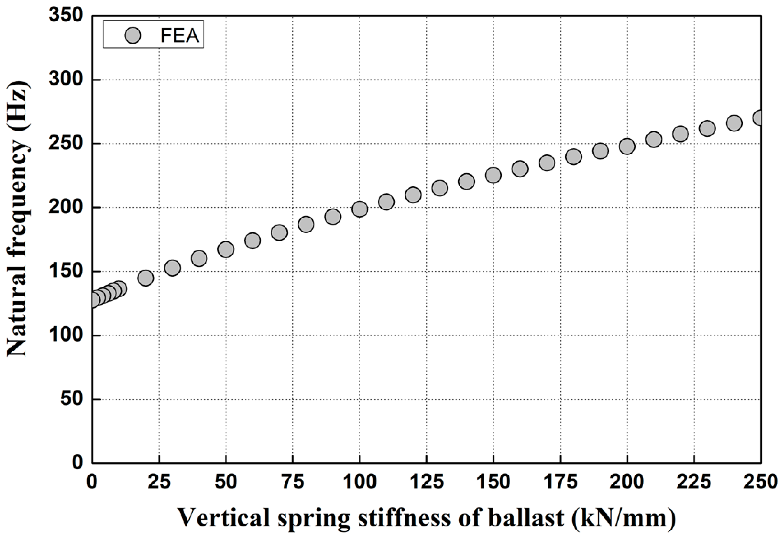
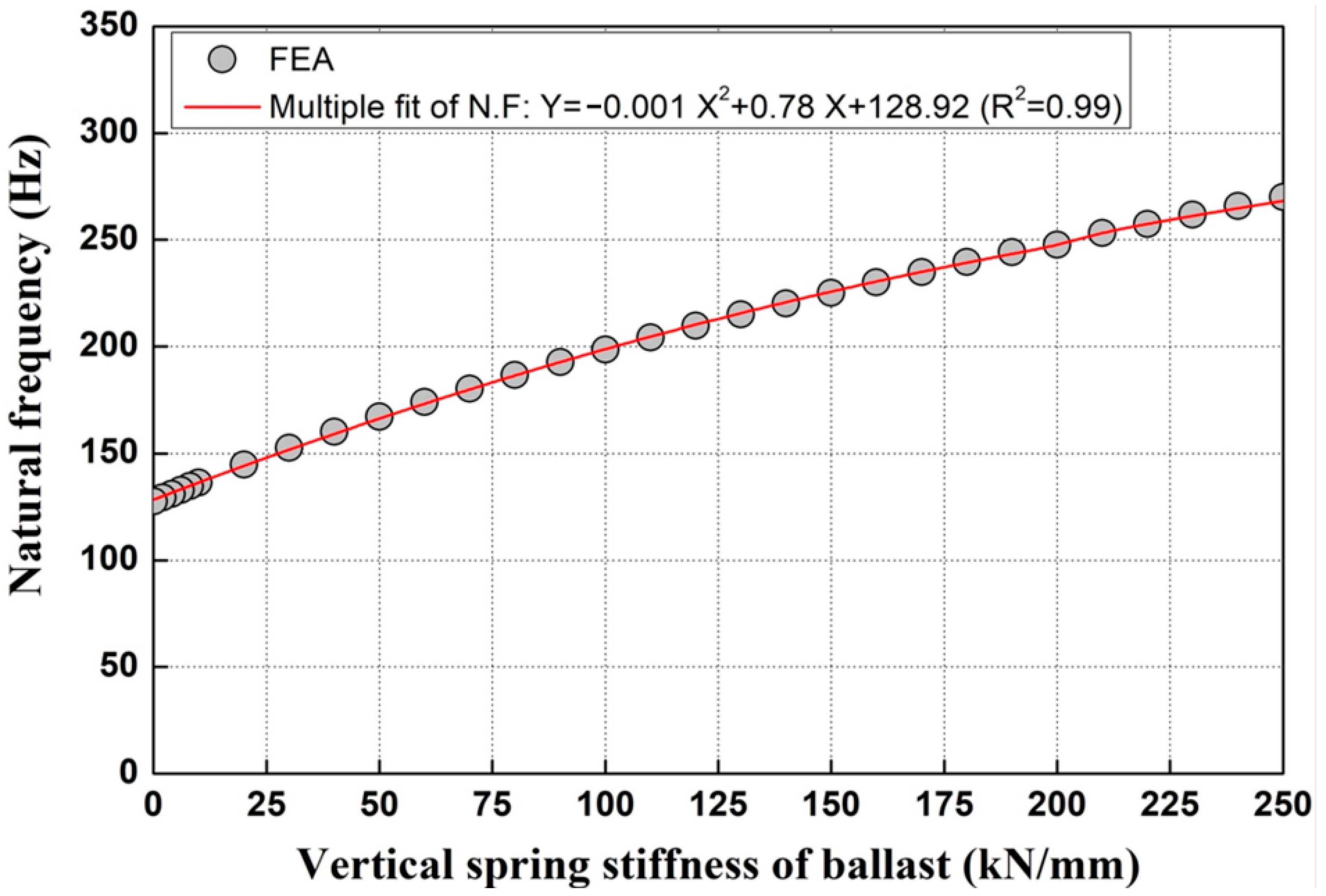
4.3. Analysis of Correlation Between Gravel Ballast Spring Stiffness and Natural Frequency

This study analyzed the correlation between the spring stiffness of the gravel ballast and the natural frequency of the sleepers using modal testing, as shown in Figure 25.
Based on the analysis of natural frequency under varying spring stiffnesses of the gravel ballast, a quadratic regression formula was proposed to estimate the natural frequency from the spring stiffness of the ballast. The spring stiffnesses of the ballast on the left and right sides of the concrete sleepers before and during construction are shown in Figure 26 and Figure 27.
The spring stiffness of the ballast under the left and right sides of the concrete sleepers on the up track before and during construction was evaluated using the spring stiffness prediction formula developed in this study. Sleepers #3, #10, and #11 on the left side, closest to the adjacent excavation site, showed spring stiffness values close to 0 kN/mm. On the right side, sleepers #3 and #11 also had spring stiffness values close to 0 kN/mm. The spring stiffness of the ballast approaching 0 kN/mm suggests a high likelihood of floating sleepers.
Figure 27 presents the spring stiffness analysis results for the ballast on the left and right sides of the concrete sleepers on the down track before and during construction. While most sleepers on the left side displayed spring stiffness within the normal range, sleepers #3 and #12 exhibited values close to 0 kN/mm. Similarly to the observations for the up track, the compromised conditions of sleepers #3 and #12 likely resulted from the impact of transverse cable installations at those specific locations.
This study investigated the spring stiffness of the ballast beneath concrete sleepers at various stages of adjacent excavation work. Most sleepers exhibited a decrease in both natural frequency and ballast spring stiffness before and during the excavation. These findings suggest that adjacent excavation activities influence both the vertical and lateral behavior of gravel-ballasted tracks. Consequently, the modal testing technique developed in this study is an effective quantitative method for assessing the condition of gravel ballast, applicable not only at sites near excavation activities but also on operational railway tracks.

5. Conclusions

This study proposed a novel modal testing technique for assessing ballast loosening and the presence of floating sleepers resulting from gravel track deformation. The key conclusions can be summarized as follows:
(1)
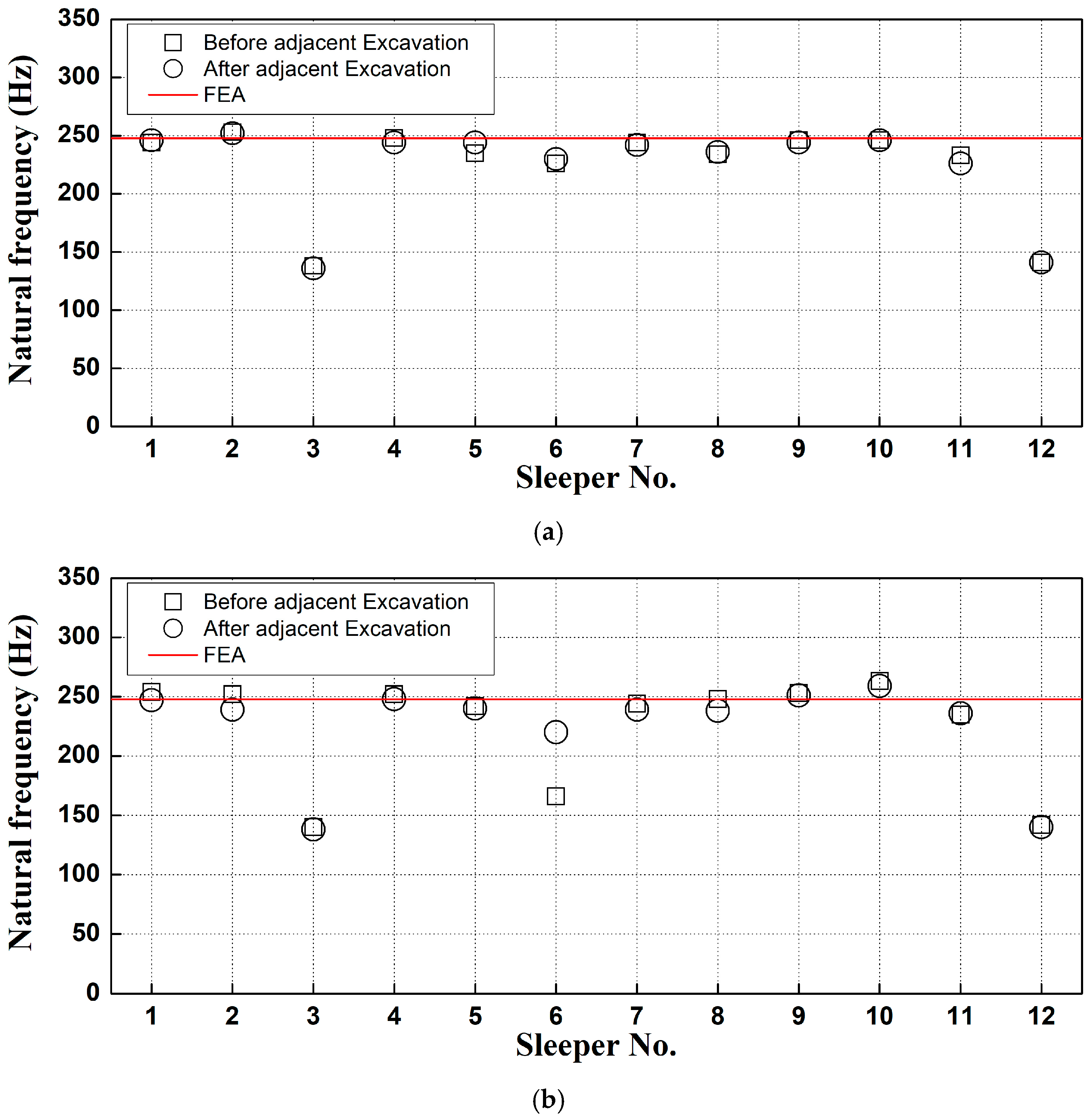
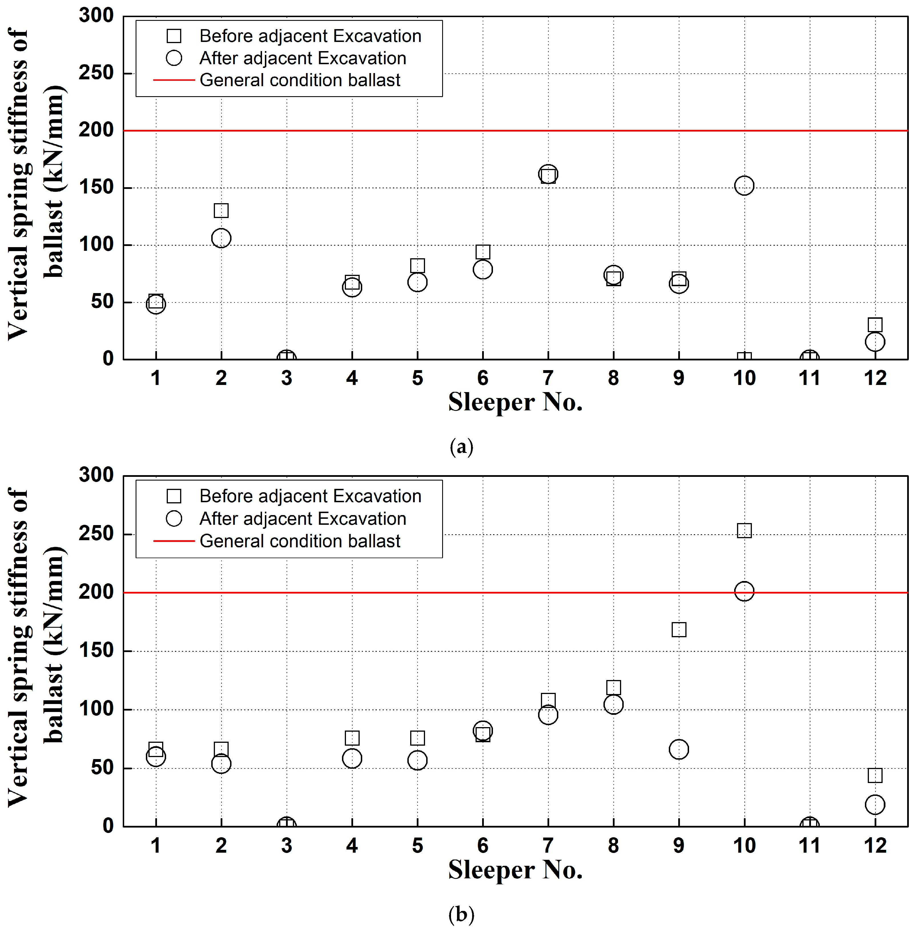
A field survey was conducted on gravel tracks adjacent to excavation sites, selecting sections with both good and poor conditions. Modal testing was employed to measure frequency response functions in areas where changes in sleeper support conditions were suspected within the ballast track. The first natural frequency at locations with floating sleepers was observed to be over 50 Hz lower than that of sleepers in good condition. Similarly, areas with insufficient ballast compaction also showed lower frequencies than those in normal conditions.
(2)
The study found that sleeper support conditions on both the left and right sides, previously assessed qualitatively through visual inspections, can be quantitatively evaluated using modal testing by analyzing frequency differences. Additionally, it experimentally confirmed that disparities in support conditions beneath the left and right sides of a sleeper—where two rails are affixed to a single sleeper, as typically seen with concrete sleepers on gravel tracks—can be effectively analyzed using this modal testing technique. Consequently, the frequency response function results from modal testing are instrumental in evaluating variations in sleeper support conditions and assessing differences in spring stiffness at rail support points.
(3)
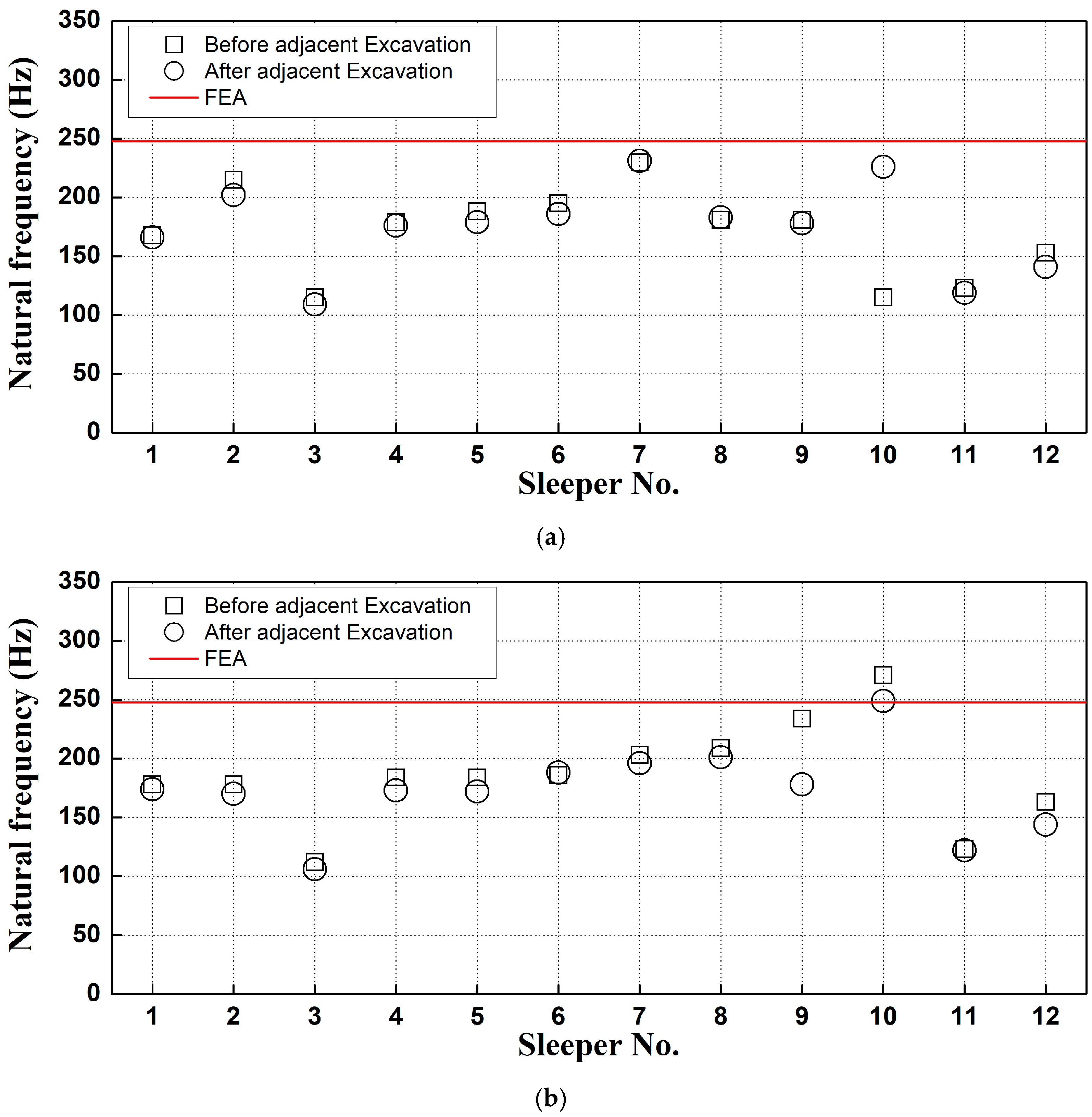
This study treated the spring stiffness of the ballast as a variable and confirmed the natural frequency of the track through finite element analysis, corresponding to changes in this parameter. The finite element analysis results showed a maximum deviation of approximately 0.91% compared to the field measurement values. This close agreement validates the use of the finite element model for simulating the track behavior under varying ballast support conditions. Therefore, the spring stiffness of the ballast and finite element modeling can be used to predict damage to gravel-ballasted track sleepers.
(4)
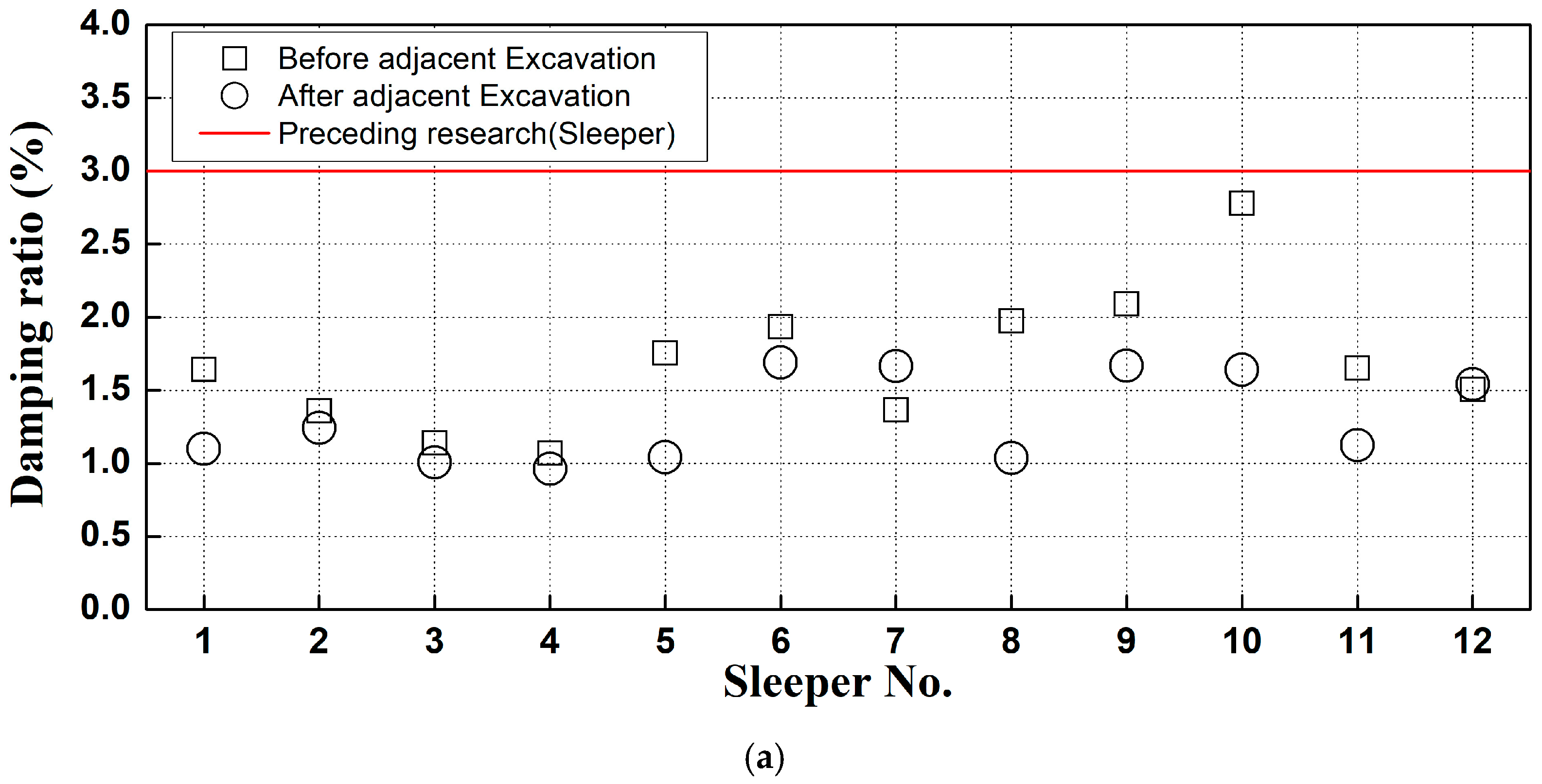
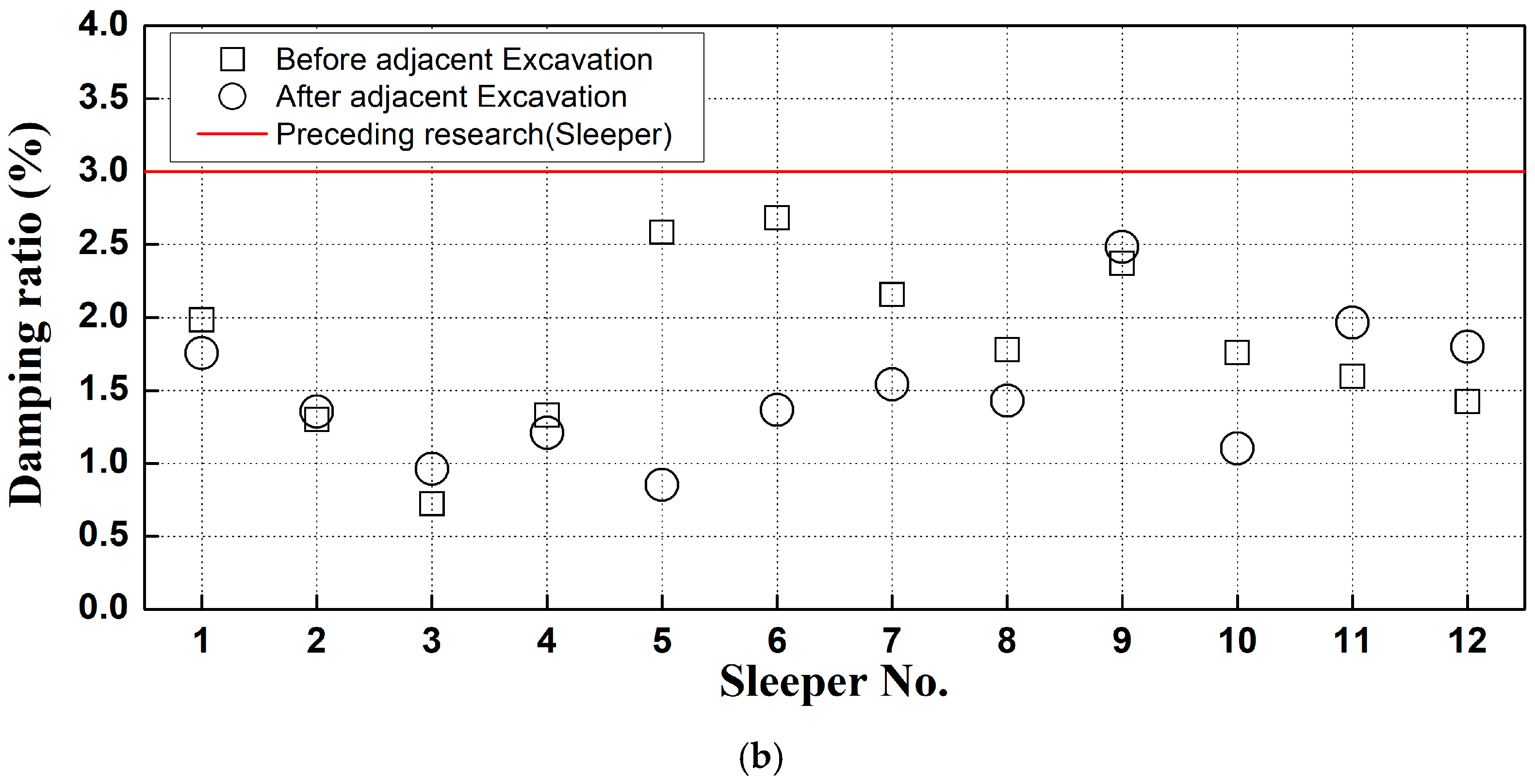
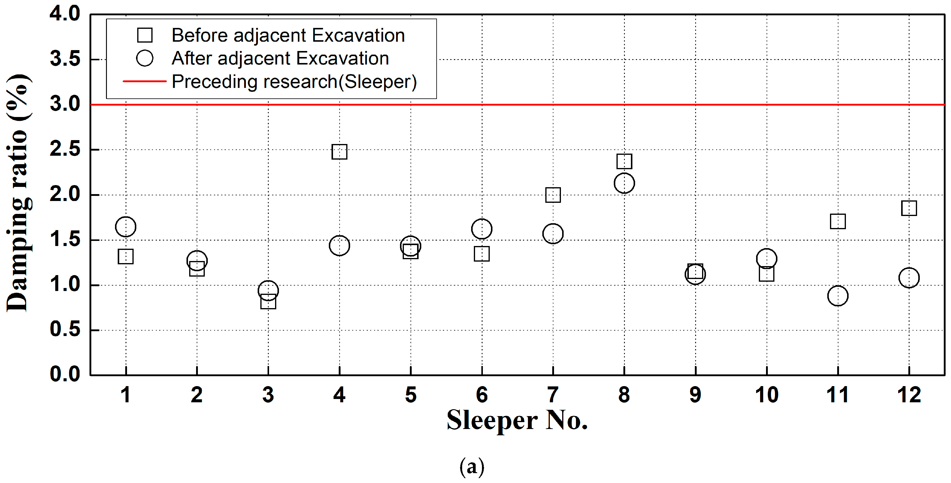
A predictive formula was developed based on the correlation analysis between ballast spring stiffness and natural frequency, enabling the calculation of ballast spring stiffness at measurement sites based on observed natural frequencies. The analysis of the damping ratio shows that, in most cases, the damping ratio decreased during construction compared to before construction. Therefore, the modal testing technique developed in this study offers a robust quantitative method for assessing the condition of gravel ballast beneath the left and right sides of concrete sleepers in gravel tracks.

Author Contributions

Conceptualization, J.-Y.C. and T.J.Y.; methodology, J.-Y.C.; software, T.J.Y. and S.-H.K.; formal analysis, T.J.Y.; investigation, J.-Y.C. and T.J.Y.; resources, T.J.Y.; data curation, S.-H.K.; writing—original draft preparation, T.J.Y. and S.-H.K.; writing—review and editing, S.-H.K. All authors have read and agreed to the published version of the manuscript.

Funding

This research received no external funding.

Institutional Review Board Statement

Not applicable.

Informed Consent Statement

Not applicable.

Data Availability Statement

The original contributions presented in the study are included in the article, further inquiries can be directed to the corresponding author.

Conflicts of Interest

The authors declare no conflicts of interest.

References

  1. Oh, S.J.; Sung, D.Y.; Park, Y. The experimental study on the effect of loose sleeper on the integral behavior of ballasted track. J. Korean Soc. Hazard Mitig. 2017, 17, 209–216. [Google Scholar] [CrossRef]
  2. Choi, J.Y.; Shin, T.J.; Kim, S.H.; Chung, J.S. Experimental Study on Dynamic Characteristics of Damaged Post-Tensioning Concrete Sleepers Using Impact Hammer. Materials 2024, 17, 1581. [Google Scholar] [CrossRef] [PubMed]
  3. Remennikov, A.; Kaewunruen, S. Investigation of vibration characteristics of prestressed concrete sleepers in free-free and in-situ conditions. Fac. Eng. Inf. Sci. 2005, 1–11. [Google Scholar]
  4. Kaewunruen, S.; Remennikov, A.M. Sensitivity analysis of free vibration characteristics of an in situ railway concrete sleeper to variations of rail pad parameters. J. Sound Vib. 2006, 298, 453–461. [Google Scholar]
  5. Kim, J.W.; Jung, H.Y. Vibrational Characteristics of the Deteriorated Railway Plate Girder Bridge by Full-scale Experimental Modal Analysis. J. Korean Soc. Steel Constr. 2012, 24, 119–128. [Google Scholar] [CrossRef]
  6. Kaewunruen, S.; Remennikov, A. Non-destructive evaluation for dynamic integrity of railway track structure. In Proceedings of the International Conference on Structural Integrity and Failure—SIF2006, Sydney, Australia, 27–29 September 2006; pp. 294–299. [Google Scholar]
  7. Ferdous, W.; Manalo, A.; Aravinthan, T.; Remennikov, A. Review of failures of railway sleepers and its consequences. In Proceedings of the 1st International Conference on Infrastructure Failures and Consequences (ICFC 2014), Melbourne, Australia, 16–20 July 2014. [Google Scholar]
  8. Kaewunruen, S.; Ishida, T.; Remennikov, A.M. Impact analyses for negative flexural responses (hogging) in railway prestressed concrete sleeper. J. Phys. Conf. Ser. 2016, 744, 012101. [Google Scholar] [CrossRef]
  9. Silva, R.; Silva, W.V.; Farias, J.Y.; Santos, M.A.A.; Neiva, L.O. Experimental and numerical analyses of the failure of prestressed concrete railway sleepers. Materials 2020, 13, 1704. [Google Scholar] [CrossRef] [PubMed]
  10. Tatarinov, A.; Rumjancevs, A.; Mironovs, V. Assessment of cracks in pre-stressed concrete railway sleepers by ultrasonic testing. Procedia Comput. Sci. 2019, 149, 324–330. [Google Scholar]
  11. Choi, J.Y.; Shin, T.H.; Chung, J.S. Damages cause analysis of concrete sleepers for sharp curved track on urban railway bridge. J. Converg. Cult. Technol. 2021, 7, 517–522. [Google Scholar]
  12. Shin, T.H. Integrity Assessment of Concrete Sleeper Using Modal Test Technique. Ph.D. Thesis, Dong Yang University, Yeongju-si, Republic of Korea, February 2023. [Google Scholar]
  13. Park, D.R. Evaluation for Ballasted Track on Serviced Railway Line. Ph.D. Thesis, Dong Yang University, Yeongju-si, Republic of Korea, August 2021. [Google Scholar]
  14. Chung, J.S.; Park, D.R.; Choi, J.Y. Evaluation of track irregularity effect due to adjacent excavation on serviced railway line. J. Converg. Cult. Technol. 2019, 5, 401–406. [Google Scholar]
  15. Sysyn, M.; Przybylowicz, M.; Nabochenko, O.; Kou, L. Identification of sleeper support conditions using mechanical model supported data-driven approach. Sensors 2021, 21, 3609. [Google Scholar] [CrossRef] [PubMed]
  16. Zakeri, J.A.; Esmaeili, M.; Mosayebi, S. Effect of sleeper support modulus on dynamic behaviour of railway tracks caused by moving wagon. Int. J. Heavy Veh. Syst. 2017, 24, 277–287. [Google Scholar]
  17. Esmaieili, M.; Zakeri, J.A.; Ebrahimi, H.; Sameni, M.K. Experimental study on dynamic properties of railway ballast mixed with tire derived aggregate by modal shaker test. Adv. Mech. Eng. 2016, 8, 5. [Google Scholar] [CrossRef]
  18. Liu, G.; Cong, J.; Wang, P.; Du, S.; Wang, L.; Chen, R. Study on vertical vibration and transmission characteristics of railway ballast using impact hammer test. Constr. Build. Mater. 2022, 316, 125898. [Google Scholar] [CrossRef]
  19. Feng, B.; Park, E.H.; Huang, H.; Li, W.; Tutumluer, E.; Hashash, Y.M.A.; Bian, X. Discrete element modeling of full-scale ballasted track dynamic responses from an innovative high-speed rail testing facility. Transp. Res. Rec. J. Transp. Res. Board 2019, 2673, 107–116. [Google Scholar]
  20. Khan, M.R.; Dasaka, S.M. Quantification of ground-vibrations generated by high speed trains in ballasted railway tracks. Transp. Geotech. 2019, 20, 100245. [Google Scholar]
  21. Benedetto, A.; Tosti, F.; Ciampoli, L.B.; Calvi, A.; Brancadoro, M.G.; Alani, A.M. Railway ballast condition assessment using ground-penetrating radar-An experimental, numerical simulation and modelling development. Constr. Build. Mater. 2017, 140, 508–520. [Google Scholar] [CrossRef]
  22. Li, B.; Peng, Z.; Wang, S.; Guo, L. Identification of ballast fouling status and mechanized cleaning efficiency using FDTD method. Remote Sens. 2023, 15, 3437. [Google Scholar] [CrossRef]
  23. Wang, L.; Meguid, M.; Mitri, H.S. Impact of ballast fouling on the mechanical properties of railway ballast: Insights from discrete element analysis. Processes 2021, 9, 1331. [Google Scholar] [CrossRef]
  24. Lam, H.F.; Wong, M.T. A feasibility study on the use of simple vibration test in the detection of railway ballast damage. In Proceedings of the 1st International Workshop on High-Speed and Intercity Railways, Shenzhen and Hong Kong, China, 19–22 July 2011. [Google Scholar]
  25. Kim, S.I.; Yu, J.Y.; Mun, J.U.; Hong, S.M.; Kim, J.T. Modal tests of railway bridges considering the type of track structures. In Proceedings of the Korean Society for Railway, Daegu, Republic of Korea, 12–13 June 2008. [Google Scholar]
  26. Yoon, T.J. Assessment Method of Railway Ballasted Track Using Modal Test Technique. Ph.D. Thesis, Dong Yang University, Yeongju-si, Republic of Korea, February 2024. [Google Scholar]
  27. ANSYS. ANSYS®2007 ANSYS Workbench, version 2021 R2; ANSYS Inc.: Cannonsberg, PA, USA, 2021.
  28. KR C-14030; Ballasted Track Structures. Korea National Railway: Daejeon, Republic of Korea, 2021.
  29. KR C-14010; General Track Design. Korea National Railway: Daejeon, Republic of Korea, 2013.
Figure 1. Representative examples of concrete sleepers. (a) Sleeper in good condition (#4); (b) poor gravel compaction; (c) sleeper with cracks (#3); (d) ballast fouling; (e) sleeper with cracks (#11).
Applsci 15 03425 g001aApplsci 15 03425 g001b
Figure 2. Overview of modal test measurements. (a) Modal test measurements setup; (b) schematic diagram of sensor measurement location; (c) detail of measurement location.
Applsci 15 03425 g002
Figure 3. Frequency response function (FRF) measurement results (up track). (a) #4; (b) #3; (c) #11.
Applsci 15 03425 g003
Figure 4. FRF analysis for all sleepers (pre-construction). (a) Up track; (b) down track.
Applsci 15 03425 g004
Figure 5. Damping ratio estimation (example).
Applsci 15 03425 g005
Figure 6. Damping ratio analysis results (pre-construction). (a) Up track; (b) down track.
Applsci 15 03425 g006
Figure 7. Numerical analysis model.
Applsci 15 03425 g007
Figure 8. Vertical spring model for gravel ballast track.
Applsci 15 03425 g008
Figure 9. Loading conditions of numerical analysis.
Applsci 15 03425 g009
Figure 10. Numerical analysis results of frequency response function.
Applsci 15 03425 g010
Figure 11. Bending mode shape analysis results for sleepers in normal gravel ballast conditions. (a) First mode (247.73 Hz); (b) second mode (319.71 Hz); (c) third mode (450.3 Hz).
Applsci 15 03425 g011aApplsci 15 03425 g011b
Figure 12. Bending mode shape analysis results for gravel track sleepers. (a) First mode with ballast spring stiffness = 50 kN/mm (167.2 Hz); (b) first mode with ballast spring stiffness = 40 kN/mm (160.12 Hz).
Applsci 15 03425 g012
Figure 13. Relationship between ballast spring stiffness and natural frequencies.
Applsci 15 03425 g013
Figure 14. Concrete sleeper left and right under support conditions (normal).
Applsci 15 03425 g014
Figure 15. Concrete sleeper measurement results.
Applsci 15 03425 g015
Figure 16. Concrete sleeper with poor support conditions on one side.
Applsci 15 03425 g016
Figure 17. Measurement results for poor under-sleeper support conditions (right side) in concrete sleepers.
Applsci 15 03425 g017
Figure 18. Measurement results for poor under-sleeper support (left side) in concrete sleepers.
Applsci 15 03425 g018
Figure 19. Concrete sleeper under poor support conditions on both sides.
Applsci 15 03425 g019
Figure 20. Measurement results for poor under-sleeper support on both sides.
Applsci 15 03425 g020
Figure 21. Natural frequency analysis before and during construction (up track). (a) Left side; (b) right side.
Applsci 15 03425 g021
Figure 22. Natural frequency analysis before and during construction (down track). (a) Left side; (b) Right side.
Applsci 15 03425 g022
Figure 23. Damping ratio analysis before and during construction (up track). (a) Left side; (b) Right side.
Applsci 15 03425 g023aApplsci 15 03425 g023b
Figure 24. Damping ratio analysis before and during construction (down track). (a) Left side; (b) Right side.
Applsci 15 03425 g024aApplsci 15 03425 g024b
Figure 25. Correlation analysis results between gravel ballast spring stiffness and natural frequency.
Applsci 15 03425 g025
Figure 26. Spring stiffness analysis results before and during construction (up track). (a) Left side; (b) right side.
Applsci 15 03425 g026
Figure 27. Spring stiffness analysis results before and during construction (down track). (a) Left side; (b) right side.
Applsci 15 03425 g027
Table 1. Sensor sensitivity in measurement system.
CategoryImpact Hammer (mV/N)Accelerometer (mV/g)
LeftRight
Sensitivity0.24100100
Table 2. Natural frequency analysis results (up track).
Category#4#3#11
LeftRightLeftRightLeftRight
First Natural Frequency183.8178.8111.9115.0123.1122.5
Table 3. Numerical analysis specifications.
ComponentsDensity (kg/m3)Elastic Modulus (Mpa)Poisson (ν)
Rail7850200,0000.3
Sleeper230030,0000.18
Disclaimer/Publisher’s Note: The statements, opinions and data contained in all publications are solely those of the individual author(s) and contributor(s) and not of MDPI and/or the editor(s). MDPI and/or the editor(s) disclaim responsibility for any injury to people or property resulting from any ideas, methods, instructions or products referred to in the content.

