Abstract
This paper presents a method for designing manipulators for man-portable UGVs (Unmanned Ground Vehicles), intended for military and counter-terrorism applications. The approach involves selecting manipulator parameters based on requirements for capabilities and a database of available components. The authors identified a gap in the existing literature regarding load definition, particularly for small robot manipulators used in Explosive Ordnance Disposal (EOD) tasks. To address this, a method is proposed consisting of three main stages: In the first stage, manipulator drives and geometric parameters are selected. In the second stage, a detailed load analysis is performed. A distinctive feature of the proposed method is the use of optimization techniques to determine the maximum possible loads during load case definition. In the final stage, topological optimization of the components is carried out. The method was validated using a selected manipulator joint of a portable robot designed for EOD tasks.
1. Introduction
Unmanned Ground Vehicles (UGVs) are widely used around the world by military forces and other organizations responsible for ensuring the security of people and property. One class of these robots is man-portable UGVs, which are primarily employed in tasks such as intelligence, surveillance, and reconnaissance, as well as the detection and neutralization of threats, including improvised explosive devices (IEDs), unexploded ordnance (UxO), and Chemical, Biological, Radiological, and Nuclear (CBRN) hazards. Each of these tasks imposes specific requirements on the robot’s platform and its equipment. The most essential component of a robot designed for IED neutralization (C-IED) is the manipulator, which is used not only for lifting and moving objects but also as a carrier for various types of sensors and effectors. When designing robot manipulators for special tasks, it is essential to consider application requirements. These requirements include ensuring sufficient working capabilities to perform tasks while addressing additional operational constraints arising from robot–environment interactions. Robots usually operate in unstructured environments with limited situational awareness on the part of the operator. Consequently, the manipulator must be robust enough to withstand collisions with obstacles. Additionally, it is sometimes necessary to use the manipulator to lift the platform to a working position in the event of a tip-over or to provide balance and support when the robot encounters obstacles. These user requirements highlight the need to optimize the mobile robot’s design to achieve the best operational parameters.
As highlighted in the literature review, existing design methods are not fully adapted to the specific requirements of EOD robot manipulators. In particular, the load cases employed in structural optimization do not accurately reflect the loading conditions arising from the specialized use of such manipulators. Therefore, a new design approach was developed—one that accounts for mission-specific capabilities, utilizes available components for project implementation, and provides load cases suited for structural optimization.
The mass of the manipulator is one of the most critical factors influencing the robot’s capabilities and energy consumption. For man-portable robots, mass is an especially significant factor and can be treated either as a parameter for minimization or as a design constraint.
This paper presents a method for designing portable robot manipulators that enables the effective development of lightweight structures optimized to meet specific application requirements.
The remainder of this article is organized as follows: After this introduction, Section 2 outlines the issue of developing new products, emphasizing the close relationship between design and optimization. Section 3 provides a review of the literature on the design and optimization of manipulators. Section 4 focuses on the specifics of portable robot manipulators and highlights the distinctive features of their design. Section 5 introduces the developed method and presents an example of its implementation for a portable robot manipulator intended for EOD tasks. Finally, Section 6 concludes the article by summarizing the main findings and discussing the results.
2. Process of Manipulator Development
Design in a systems approach can be presented in the form of the so-called V-model of the product life cycle [1]. The V-model is an illustration of the product life cycle consisting of two branches in which the processes are arranged in the shape of the letter V. The left part lists the processes related to the design process, such as requirements definition, feasibility study, top-level system design, subsystems and components, and production and integration. In the right branch of the model, for each process of the left branch, there are corresponding processes verifying the compliance of the results with the requirements.
In the “creative” processes presented in the left branch of the V-model, one can recognize the approach to design also implemented in advanced CAD environments called top-down design. In this approach, the highest level of the system is defined first and then the system is decomposed into smaller subsystems and components, which are subject to detailed design, production, and integration. This approach supports maintaining the compliance of the results with the requirements. In the opposite approach to design (bottom-up), the components are defined first and then higher-level subsystems are built from them. The final effect results from the capabilities and characteristics of the components. A comparison of both types of design approaches is presented, for example, by Crespi et al. [2].
The design process of a robot manipulator is inherently linked to optimization. According to the principles outlined by Osiński [3], the design process should adhere to two key rules: (1) the structure must meet all fundamental construction conditions without exceeding a set threshold, and (2) the design should be optimized under given constraints based on established optimization criteria. The first principle emphasizes that the design must be guided by clearly defined requirements. The second underscores that decisions made during the design process inherently constitute an optimization process. Optimization involves finding the best solution to a problem based on specific criteria, such as cost, reliability, accuracy, or task completion time, while considering existing constraints [4]. An example of an approach to optimize construction is design for assembly (DFA) [5]. The process of optimization includes developing a model of the problem, defining evaluation methods for potential solutions, and identifying an optimal solution using appropriate mathematical techniques [6].
The task of designing manipulators is a complex issue that requires optimization in multiple aspects. This includes selecting parameters for drive mechanisms, defining kinematics, and optimizing the supporting structure of the mechanism. Structural optimization can be approached through various methods, such as size optimization, shape optimization, and topology optimization [7]. Size optimization focuses on selecting the optimal parameters that describe the geometry of the structure, such as wall thickness, dimensions, or the number of holes. Shape optimization involves modifying the mesh describing the component according to predefined criteria while maintaining its topology. In contrast, topology optimization is a more general approach that optimizes the material distribution of a part to accommodate the specified load conditions. The topology optimization process begins by defining the boundary conditions, including the optimization area, passive regions, constraints, and loads. The optimization criteria may involve minimizing compliance while reducing the component’s volume. For manipulator construction, it is particularly important to account for the varying magnitude and direction of loads on individual segments, which must be considered in subsequent calculations.
3. Literature Review on Manipulator Design and Optimization Methods
There are numerous examples of manipulator design optimization in the literature. In this work, we primarily focus on optimization of the supporting structure. The reviewed approaches can be divided into three main categories: First, many studies address the optimization of fundamental manipulator parameters, referred to as size optimization (as discussed in the previous chapter). Next, researchers explore topology optimization or a combination of size and topology optimization. Finally, the third category focuses on the selection of load cases appropriate for the structural optimization of robot manipulators.
3.1. Size Optimization
The first example of size optimization implementation can be found in [8], where the authors optimized an industrial manipulator to increase energy efficiency for selected tasks. Employing several optimization methods, they selected the manipulator’s parameters based on indicators such as the GCI (Global Condition Index) and SLI (Structural Length Index), the latter being the ratio of the total length of the robot’s elements to the volume of its working space. In [9], the authors used a genetic algorithm to optimize a 7-DOF manipulator. By applying the SLI, GCI, and MDCI (Modified Dynamic Conditioning Index) as optimization criteria, they enhanced the robot’s energy efficiency. The procedure and results of a multi-criteria optimization for a 7-DOF robot manipulator are presented in [10], taking into account criteria such as the GCI and SLI. An analysis of variance (ANOVA) was then conducted to determine the impact of various parameters on the manipulator’s performance. In [11], the authors minimized the energy required for packaging tasks on a production line by selecting optimal arm lengths for an SCARA robot. In [12], the authors carried out multi-criteria optimization in which, in addition to the geometric parameters of the manipulator, the gear parameters in the manipulator joints were selected. The authors’ goal was to minimize the mass-to-load ratio and maximize the natural vibration frequency of the structure. The authors used the NSGA-II algorithm and validated their results using ADAMS simulation software. Thanks to optimization, they achieved a 10 percent mass reduction. In [13], the authors carried out multi-criteria optimization in which they selected parameters describing the geometry and drives of the manipulator to improve parameters such as stiffness, natural frequency, and mass. In [14], the authors proposed a manipulator design method in which the design parameters and the selection of manipulator drives were optimized. The mass of the manipulator was minimized while maintaining the limitations resulting from the assumed dynamics of the robot. Parametric optimization was performed in the Ansys program, and a manipulator model simulated using the ADAMS simulation environment was used to select the drives. In [15], the authors optimized the manipulator by minimizing the size of the manipulator and maximizing the volume of the working space. In [16], the authors optimized the link lengths of the anthropomorphic manipulator. The authors defined a global comprehensive performance index that takes into account the manipulability, the condition number of the Jacobian matrix, and the stiffness of the manipulator end.
3.2. Topology Optimization
There are also numerous examples in the literature where topology optimization is applied in manipulator design, often in combination with parametric optimization of geometric parameters. For instance, in [17], the upper arm of an industrial manipulator used in welding was optimized by reducing its mass and increasing its natural vibration frequency. In [18], a multi-criteria optimization of an industrial manipulator was carried out to minimize both initial and running costs.
As shown in [19], a serial manipulator can be optimized by integrating topology optimization at the part level with parametric optimization at the system level. The researchers first developed a stiffness model of the manipulator and then determined typical load values and configurations. Topology optimization was performed on individual parts, while parametric optimization was used to distribute mass across different components.
According to [19,20], the most significant mass reduction can be achieved by combining parametric and topology optimization when designing manipulator structures.
3.3. Topology Optimization and Detailed Analysis of Manipulator Loads
Many publications touch on the subject of load selection for optimization purposes. Most often, the process is carried out on examples of industrial manipulators. In [21], the authors performed topological optimization of an industrial manipulator arm, taking into consideration the variability of the load direction during arm rotation. The authors assumed that the arm is loaded at the end with a vertical force. The optimization performed takes into account the loads present when the arm is rotated from an angle of 0 to 170, with 10-degree resolution. In [22], the authors dealt with minimizing the mass of an industrial manipulator arm using topological optimization. The authors proposed methods to take into account multiple loading conditions in density topological optimization by introducing weighted sums of material densities obtained for different loading cases. In [21,23], the authors proposed a method to solve a similarly defined problem based on the processing of the resulting topology created by superposing solutions for individual load angles.
There are also publications where authors perform more advanced analysis on the subject of load selection for optimization purposes, often illustrated by examples involving industrial manipulators. In [21], a topological optimization of an industrial manipulator arm was performed under varying load directions during arm rotation. The researchers assumed a vertical force acting at the arm’s end, and accounted for rotations from 0 to 170 degrees in 10-degree increments.
In [22], the same group aimed to minimize the mass of an industrial manipulator arm using topology optimization. They proposed methods to handle multiple loading conditions by introducing weighted sums of material densities obtained for different load cases.
Finally, in [21,23], the authors addressed a similarly defined problem by processing the final topology generated through superimposing solutions for individual load angles. This approach highlights how combining results from multiple load configurations can yield a more robust design.
The work presented in [24] involved topological optimization of upper-limb exoskeleton components using two methods. The authors performed optimization for a single configuration, for which the structure stress values were the highest. It was assumed that the arms were straightened horizontally and the maximum accelerations achievable by the arm joints were assumed as loads. In [25], the authors presented the process of designing a manipulator with a parallel structure intended for palletizing. To assume the loads for topological optimization, they analyzed the loads in individual manipulator joints for the full range of movement of the members for the assumed transferred weight. The authors adopted one selected load condition for optimization. In [26], the authors presented a method for optimizing a lightweight anthropomorphic manipulator. Typical configurations and loading conditions were analyzed to identify loads on the arm. Various loads were used to optimize the components. Each load case was divided into bending, shear and tension loads. In [19], the authors presented a method for optimizing a manipulator intended for spray painting, using topological and parametric optimization. The calculations used load cases that generated the largest effector deflection for 30 randomly generated manipulator configurations. The deflections were calculated via the FEM using the model before optimization.
Analysis of optimization methods—particularly topology optimization—applied to designing portable robot manipulators for special tasks has shown that existing approaches from the literature cannot be directly used. This limitation arises from the distinct parameters and functionalities of such manipulators.
For example, because these robots are operated manually, structural stiffness and joint clearances have a lesser impact on movement precision. The operator relies on camera feedback that provides absolute information about the manipulator’s end-effector position, and the manipulator typically moves at low speed. In the context of EOD tasks, high-speed maneuvers are neither required nor advisable. In fact, careless or imprecise movements could cause the detonation of the transported load. As a result, criteria favoring high speed or extreme structural stiffness are less relevant when optimizing portable robot manipulators for special tasks.
In contrast, industrial manipulators are generally designed to maximize stiffness, with sufficiently high safety factors to prevent damage even in the event of a collision. Portable robots, however, are expected to lift relatively large masses compared to their own weight. This requirement necessitates lower safety factors in the structure. Consequently, accurately estimating loads becomes essential.
Most references in the literature adopt the most severe identified load case for optimization. In some instances, equivalent loads are introduced to account for accelerations [27]. A more detailed analysis of how various manipulator configurations influence topology optimization can be found in the works of Srinivas [21,22,23].
Nevertheless, these studies typically only consider loads resulting from gripping and moving objects, which makes sense for industrial manipulators where collisions are emergency scenarios. By contrast, portable robot manipulators for special tasks must account for all possible operating states and configurations, including those unusual from the perspective of classical industrial robots. Therefore, any optimization procedure should incorporate such atypical load conditions.
4. Specificity of Portable Robot Manipulators
The requirements for robot manipulators differ significantly from those of industrial robots. Key distinctions include a much lower structural mass, a higher load-to-weight ratio, and greater collision resistance. Because these manipulators are teleoperated and operate in highly unpredictable environments, their drive speeds are typically low. Moreover, the precision needed only has to match human capabilities rather than the higher standards of industrial robots. For tasks such as EOD, careless or imprecise movement could trigger hazardous events, so high speed is neither necessary nor advisable.
Another important feature of these solutions is their ability to maintain position and orientation when drive power is lost, coupled with the inability to use automatic home positioning once the device is started. Portable robot manipulators also come in a wide variety of kinematic configurations. Most have serial structures, usually based on rotary joints. Unlike parallel mechanisms driven by linear actuators, which are common in heavy-duty applications, rotary drives provide the required workspace and allow the manipulator to fold into compact dimensions for transport.
Most solutions of this type have a modular structure. In lightweight robots designed for special tasks, these joints are powered by electric motors equipped with gears to achieve the required torque and speed. The choice of gear type depends on various factors, but self-locking gears—such as worm or spiroid gears—are frequently used. Designs employing gears, such as harmonic or cycloidal drives, also exist.
In this study, we assume that worm gears with integrated overload clutches are employed as the final drive stage. This solution provides joint compliance when the load limit is exceeded. Consequently, the worm gear housings serve as the manipulator’s rotary joints.
It is also assumed that, during the design stage, various components and design solutions can be freely considered, from which the best option is ultimately selected to build the manipulator. The proposed approach introduces a so-called “library of solutions”, featuring worm gear drive components that meet the aforementioned requirements. Moreover, because the robot’s movements are sufficiently slow, the resulting loads can be treated as quasi-static.
Additionally, we assume that any dynamic loads—occurring, for instance, during collisions or when using devices such as shotguns, pyrotechnic disruptors, or window breakers—may lead to momentary overloads. In such situations, the overload clutches in the joints would engage or the robot might temporarily lose stability but the structure itself would remain undamaged.
5. Method for Designing Manipulators for Man-Portable UGVs
This article presents a multi-stage approach that yields a manipulator design with enhanced operational capabilities that simultaneously adheres to user requirements—such as staying within a specified mass limit. The general diagram of this approach is shown in Figure 1. It combines elements of a top-down methodology, where design begins with broad requirements that are then refined, and a bottom-up methodology, where specific solutions are used to build a more complex structure. This combined strategy reflects both the unique nature of special-task robots and the practical goal of implementing the optimized design, rather than pursuing it merely for research.
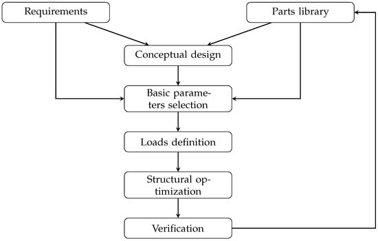
Figure 1.
Logical diagram of the algorithm for optimizing mechanical structures of manipulators of small UGVs.
When designing and optimizing robot manipulators for specialized tasks, the drives are selected to ensure the required working capabilities, such as lifting specified loads. The manipulator’s supporting structure must then be chosen and adapted to accommodate all potential load cases, including accidental ones. Consequently, the proposed methodology can be divided into three stages: In the first stage, the manipulator’s basic geometric parameters and drives are selected. In the second, the maximum loads on the structure are determined based on the requirements and the previously chosen parameters. Finally, the third stage involves topological optimization of the manipulator components. A detailed description of each stage is provided later in the article.
5.1. Conceptual Design
In the first stage of the design process, the use scenarios are analyzed and requirements for the structural elements are established. The chosen functionalities are then translated into specific requirements and parameters for the system’s subsystems, covering not only the desired working capabilities but also strategic, economic, and marketing considerations. At this stage, a high-level system architecture is defined. Based on these defined requirements and the system architecture, a conceptual design of the robot is created, specifying fundamental design choices.
5.2. Basic Parameters Selection
Following the proposed methodology—and based on the analysis of requirements and available components—the parameters of the manipulator are determined. These include the distances between joints and the sizes of the drives (i.e., required torques), ensuring the necessary functionality while adhering to the imposed mass limit. The detailed procedure is described in [28], where a Pareto front of solutions is obtained. From this set, the optimal design is selected as the basis for subsequent stages of the process.
Next, the robot manipulator activities are analyzed in terms of the loads generated during operation. The most obvious function is to move objects using the manipulator. For specialized robots, it is often crucial to specify parameters such as the maximum mass that can be carried with the manipulator fully extended horizontally, and the maximum mass that can be lifted near the platform’s edge. These key parameters guide the selection and optimization of the manipulator’s drive systems. However, the operator may occasionally attempt to lift objects exceeding the manipulator’s capacity or the robot’s stability limits. In such cases, the load on the manipulator is restricted by activation of overload clutches or by the robot losing stability.
There are also scenarios where a heavy object must be moved from a stationary position—one resting on the ground, for example. In these situations, the manipulator’s tip can be used to push or pull the object, whether by adjusting the manipulator joints or by driving the mobile platform itself. This includes tasks like clearing obstacles, opening doors, or even towing a small vehicle. Further examples of such specialized operations can be found in [28].
5.3. Load Cases Definition
In the next stage of the procedure, the manipulator selected from the Pareto front is analyzed to identify the maximum loads that may occur in its structure. These loads can be grouped into two categories: those that remain constant regardless of the manipulator’s configuration, and those that vary according to configuration. For joint bodies, the loads stemming from the worm gear drive are transmitted via the contact surfaces of the worm and worm wheel bearings. When the gearbox operates at maximum torque, the magnitudes and directions of these loads depend solely on the drive’s direction of operation (two possible orientations).
Additional loads—such as the forces and moments acting on the joint bearings that also support the worm gear wheel—fluctuate based on the manipulator’s configuration. To determine their maximum values, one must consider scenarios in which the movement of the manipulator tip is obstructed (e.g., by an obstacle). Under these conditions, with the manipulator drives at maximum torque, the joint loads will depend strongly on the manipulator’s specific configuration. Identifying these peak loads for various orientations is essential for the subsequent component optimization stage.
As an example, the maximum joint loads can be tested on a typical five-degree-of-freedom (5R) manipulator structure designed for EOD robots where all joints are rotary.
The structure of the manipulator is shown in Figure 2. It consists of the following elements: element 1, the drive moving the manipulator in vertical axis 1; element 2 driven by a joint with axis 2 perpendicular to the axis of element 1; elements 3 and 4 with drives on axes parallel to axis 2; and element 5, a gripper that can rotate around its longitudinal axis, perpendicular to drive axis 4. During the analysis, the structure of the manipulator is simplified by locking the rotation in axis 1 so all the elements move in a common plane. The structure will be considered as a flat mechanism, which is sufficient for performing load analysis.
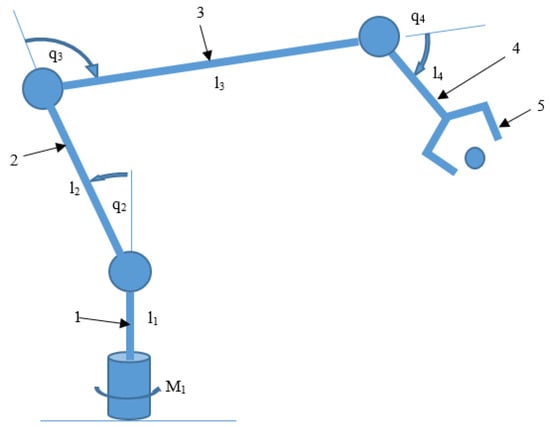
Figure 2.
Simplified model of 5-DOF manipulator.
The maximum loads in the event of a collision of the manipulator gripper with an obstacle can be determined by searching for a manipulator configuration that will cause maximum loads when trying to move the joints with the maximum torque while the movement of the tip of the gripper is blocked. It can be noticed that, after blocking the gripper’s movement, the moments generated in axes 2, 3, and 4 do not have radial components in these axes and the axial components cannot be greater than the maximum torque transferred by the overload clutches of these joints. The situation is different in the case of the driving torque in axis 1. When the gripper is blocked, radial moment loads are generated in joints 2, 3, and 4, the value of which depends only on the manipulator configuration. These load components of joints 2, 3, and 4 are not limited by overload clutches, but when the load limit is exceeded, the robot will fall over, which will prevent further load increase. The example of manipulator joint 3 will show how to calculate the load in the direction we are interested in.
Let us assume that drive 1 of the manipulator operates with the torque and the gripper rests against an obstacle so the movement is blocked. The value of the force F that is exerted on the obstacle is as follows:
where are the distances between joints 2 and 3, 3 and 4, and 4 and the end of the gripper (Figure 2); are simplified notifications of ; and are the internal coordinates of the manipulator’s joints.
In joint 3, the torque resulting from the force F acting on the arm equal to the distance of joint 3 from the end of the gripper (Figure 2), marked as , is
determined in the global coordinate system. To determine the moment in the coordinate system related to joint 3, the joint we are interested in, we need to rotate it by angle beta, which is
Representing in the coordinate system associated with arm 3, marked as , we obtain
where
Since, to perform further optimization of the joint body, it is necessary to determine the largest loads that can be achieved in selected directions, the angle parameter is introduced to control the angle at which the greatest loads are sought. After projecting the moment vector onto the direction we are interested in, rotated by the angle , we obtain the radial moment in joint 3 in the direction:
where
To find the largest radial moments in joint 3, an optimization procedure is used in which the searched parameters are the coordinates , for which the value of the objective function, which is , in the direction we are interested in is the largest.
Limitations resulting from geometric and force constraints are introduced as unequal constraints: Minimum and maximum values of internal coordinates (limit positions) are introduced as constraints resulting from geometry, and configurations in which the joints and gripper tip collided with the mobile platform are eliminated. As inequality constraints resulting from statics, the maximum force that can be exerted on an obstacle, which results from the specified maximum friction force of the robot platform against the ground, is limited and a limitation of the moment resulting from the action of this force on the arm is introduced, resulting from the adopted configuration of the manipulator. It is assumed that, after a certain moment, the platform would start to tip over or rotate. The constraints can be written as follows:
where
- , —position limits at joint i
- —torque at joint i
- —maximum torque at joint i
- —radial torque at joint 1
- —maximum radial torque at joint 1
- —radial force at joint 1
- —maximum radial force at joint 1
The calculations are performed using the Fmincon function in MATLAB R2023b. The procedure to find the optimal value of a nonlinear function with inequality constraints uses the interior point algorithm [29]. This is an algorithm that allows finding the local minimum of the function. Therefore, to find the global minimum of the function, a modification is introduced in the algorithm that causes the search to be run multiple times from different starting points selected in the coordinates space. As a result of the algorithm, configurations are obtained that generated the highest radial moment loads for the directions defined by angle . For joint 3, the results of which are the most interesting, the course of the maximum radial moment depending on the search angle is presented in Figure 3 and Figure 4.
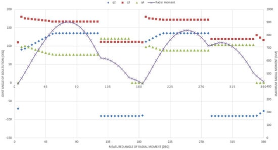
Figure 3.
The maximum radial moment in joint 3 depending on the measured angle and the coordinates of the solution (the direction of the moment in joint 1 is positive).
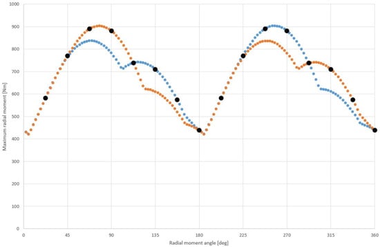
Figure 4.
Maximum values of the radial moment in joint 3 of the manipulator depending on the considered direction (orange for positive direction, blue for negative direction). Black points indicate the maximum moment values that were used for further calculations.
Figure 3 shows the values of the maximum radial moments loading the manipulator joint, which is marked with a continuous line, and the corresponding values of the internal coordinates of the manipulator, which are marked with points. The angle at which the maximum values of moments are tested is marked on the X axis. Figure 4 shows the obtained maximum values of radial moments for both directions of the moment acting in joint 1. The black points indicate the maximum value of the moment that is taken into account in the further part of the calculations. The points are placed for the angle changing every 22.5 degrees.
In the simulation, the moment which acts on axis 1 is 70 Nm. It can be noted that there are configurations in which blocking the gripper movement at such a moment in the base of the manipulator can generate up to 900 Nm of torque in the radial direction in joint 3 of the manipulator. So, for these configurations, the torque is amplified more than 12 times. The selected manipulator configurations that generate the highest torque loads acting in various radial directions are shown in Figure 5.
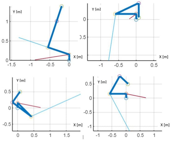
Figure 5.
Selected configurations for which the radial moments in joint 3 are the highest (markings: thick blue lines—manipulator links, wheels—manipulator joints, thin blue line—torque vector in joint 3, thin red line—torque vector in joint 2).
Figure 5 shows the configuration of the manipulator links, with the base located at point (0,0) of the coordinate system. It can be observed that the configurations found to generate the largest radial moments in manipulator joint 3 (acting in the selected directions) are those in which the gripper tip lies close to the rotation axis of joint 1. Theoretically, the force with which the gripper presses against an obstacle in such a position tends to approach infinity as the contact point nears the axis of joint 1. However, in practice, either a loss of grip or a loss of robot stability prevents the forces from exceeding certain limit values. The moments determined using the described procedure should be taken into account when defining the individual load cases for the next stage—namely, the topological optimization of the joint body. These load cases are obtained by adding the loads calculated in the aforementioned routine to those resulting from the maximum torque in the joint’s worm gear.
The load distribution in the worm gear is determined using generally known methods presented, for example, in [30]. As an example, the distribution of maximum forces in the worm wheel bearings depending on the angle of radial torque acting on joint 3 is shown in Figure 6.
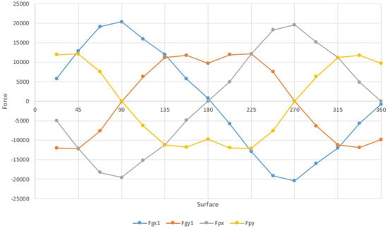
Figure 6.
Forces acting on the selected bearing surfaces of joint 3, depending on angle of maximum radial torque.
The sum of constant forces and forces that vary depending on the considered direction defines individual load states in the next stage of the methodology, where topological optimization of the joint body is performed.
5.4. Topological Optimization of the Manipulator Structure
The forces calculated in the previous stage are used to define load cases in the topological optimization of robot components. The further optimization process will be demonstrated using the example of the manipulator joint body 3. For the selected body, an optimization space is defined in which the solution to the problem is sought as well as a passive space that is not subject to modification during optimization (Figure 7).
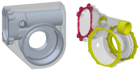
Figure 7.
Left side—design space (transparent) and passive space (gray) of the manipulator joint, right side—boundary conditions: red indicates the part restraint, yellow indicates the forces acting on the part surfaces.
The project space is constructed so that its volume is as small as possible but does not limit the operation of the optimization algorithm. This space is also appropriately cut out to provide space in the resulting component for gear components, cables, and electronic systems. The passive space is constructed from thin-walled primitives. This space defines the interfaces for attaching the joint components, to which constraints and loads will also be applied. The passive space is built in such a way as to ensure tightness in the resulting structure and to guarantee the possibility of running cables between individual compartments of the body. The passive space is functionally a fully fledged model of the gear body, but it does not take into account the strength requirements. Topological optimization aims to modify the body so that it also meets the strength conditions. It should be noted that the passive space and design space models are related to a given transmission and, in accordance with the adopted methodology, are defined at the part library level. The boundary conditions are shown in the passive space (Figure 7). The part is fixed on its left surface (red marks) and the loads are applied on the surfaces which are interfaces to bearings and other components (yellow marks). The figure shows one of the load cases where the maximum radial moment is at an angle of 90∘.
Firstly, calculations with a lower-resolution mesh are performed. The mass is minimized within the limits resulting from the maximum stresses. The results show that it is possible to reduce the mass of the part to 25% of the mass of the initial design space. Then, optimization on a higher-resolution mesh is performed. To reduce calculation time, settings of the optimization are changed to maximize the stiffness of the structure with the imposed mass reduction condition of 25% of the mass of the design space. The body material is EN AW-7075. The optimization result is shown in Figure 8. Calculations are performed using the SIMP method [31] implemented in nTopology software [32].
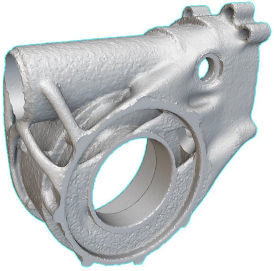
Figure 8.
Result of the topology optimization of the joint.
For comparison, calculations are made for a different count of load states which differ with the angle of action of the maximum radial moment in the joint. Sixteen load states are defined in which the radial moment angle changes every 22.5∘ (Table 1).

Table 1.
Load cases resulting from variable directions of radial moment loads. The table shows the forces (named Fg1 and Fp) that act on the body surfaces through the joint bearing in the X and Y directions.
The following calculation variants are considered:
- Four load states differing in the direction of force action every 90∘ (Figure 9—left);
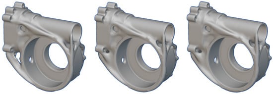 Figure 9. Optimization results considering 4, 8, and 16 load directions. The SIMP method, compliance minimization, volume reduction of up to 35% of the design space, and results smoothing are applied.
 - Eight load states differing in the direction of force action every 45∘ (Figure 9—middle);
- Sixteen load states varying in the direction of force action every 22.5∘ (Figure 9—right).
As can be seen in Figure 9, the optimization results are very similar regardless of the number of load cases considered.
The analysis shows that the volumes of the resulting components overlap by 95.5% for the comparison of results 1 and 2 and by 99.6% for the comparison of results 2 and 3. It can be concluded that, for models similar to those presented in this work, it is sufficient to use four load states, differing in the radial moment with a variable direction every 90∘. It should be emphasized, however, that the results of topological optimization may vary depending on, for example, the design space and the size of the mesh, so it is a process in which it is worth testing many solutions using the trial and error method. Additionally, the solutions found are of a local optimum nature. Adding manufacturing constraints allows for obtaining a better result from the point of view of the objective function.
6. Discussion
In this paper, a method for selecting manipulator parameters based on user requirements and a “library of solutions” (available components) was presented. The approach is iterative and consists of the following stages: In the first stage, initial manipulator parameters are chosen to satisfy user requirements and maximize specific performance indicators, treating mass as a flexible (uneven) constraint in the optimization. In the second stage, maximum loads in the construction are identified. Once the load cases are defined, the mass of individual components is minimized through topological optimization.
6.1. Practical Applications and Flexibility
This methodology is primarily designed for robot manufacturers who already have a range of parts and modules. It enables them to utilize their existing inventory while customizing the final product to better meet customer needs. By integrating topological optimization, the method emphasizes reducing one of the most critical operational parameters—manipulator mass—without compromising key performance indicators.
It is essential to highlight that the proposed method serves as a tool for manipulator designers. Constraints and objectives must be tailored to each specific project. In some instances, minimizing mass may be the primary objective; in others, mass may merely be a constraint while different performance metrics (e.g., reach, lifting capacity) are optimized. Designers must also determine whether to account for dynamic loads resulting from rapid movements or impacts. In the provided examples, key indicators included the ability to lift heavy objects at maximum reach and near the robot base, as well as the overall reach of the manipulator—parameters that are inherently influenced by mass.
Models derived from topological optimization are incorporated into the solution library. Subsequent iterations of the procedure can then assess whether the mass reductions significantly impact the optimization of the manipulator’s fundamental parameters, potentially enhancing performance further. The results obtained in this process also serve future projects.
Although the presented application example focused on a specific manipulator joint, the approach employed can be applied to any component of the manipulator’s kinematic chain.
6.2. Limitations
Overall, the presented method systematizes the design and optimization of manipulators. However, one should bear in mind its inherent limitations. The topology optimization process requires specification of various input parameters, including material properties, load conditions, and boundary conditions. These factors are essential in shaping the ultimate design outcome. However, determining the ideal combination of input parameters is often unclear and demands significant expertise and experience for accurate definition. Moreover, even slight changes in these input parameters can greatly influence the final design, making it difficult to attain a robust and reliable solution. Despite these constraints, our research demonstrates that applying the proposed approach positively impacts the manipulator’s ability to meet stringent user requirements.
6.3. Significance
Optimization in the design process of robotic manipulators plays a key role in shaping parameters that determine their functionality, performance, and adaptability to various applications. Modern approaches to manipulator design, as indicated by the analysis of the state of the art, are highly diverse, leading to a lack of consistency when comparing achieved solutions. This issue stems from the variety of criteria, tools, and methods employed in the design process. The proposed methodology addresses this gap by enabling the unification of design approaches and introducing a level of systematization that has been challenging to achieve thus far.
A fundamental aspect of this methodology is a new approach to defining load cases, which is particularly important for portable manipulators used on mobile robots working in an unstructured environment. Unlike traditional methods, which primarily focus on loads from object manipulation, our approach incorporates a more demanding set of loading conditions which results from interactions with the environment such as collisions of the end-effector. The identification of these critical loads is achieved through an optimization-driven process. This method ensures that the optimized structure remains robust under real-world conditions. This novel perspective on load case definition is essential for enhancing both the reliability and operational capabilities of mobile robotic manipulators.
One of the key elements of the proposed approach is the ability to select a specific optimization criterion, which allows the design process to be directed toward desired outcomes. For instance, the criterion might involve minimizing the mass of the manipulator, which is particularly important in mobile systems, where reducing weight directly impacts energy consumption and transport efficiency. Another potential criterion is the selection of actuators with specific parameters, such as torque or speed, which define the manipulator’s precision and motion dynamics. Additionally, optimization may include maximizing the range of motion, increasing the manipulator’s versatility across diverse working environments. The integration of load case refinement with these optimization criteria ensures that the manipulator is not only lightweight and efficient but also structurally adapted to withstand the diverse and unpredictable conditions of field operations.
6.4. Future Directions
The absence of benchmarks in this work directly results from the diversity of design systems, which currently prevents clear comparisons between individual methods. However, the uniqueness of the proposed solution lies in introducing a methodology that not only systematizes the design process but also lays the groundwork for building such benchmarks in the future. For example, in subsequent stages, computational efficiency during the calculation of optimization parameters could be analyzed depending on the computational hardware used, enabling a comparison of methodology implementation efficiency. Evidence supporting the effectiveness of systematization in manipulator design can be found in the literature on mobile robotics. Studies on manipulators used in space exploration (e.g., NASA or ESA projects) have shown that a consistent approach to optimization, such as establishing standard energy efficiency criteria, has significantly improved the design of mechanisms intended for operation in extreme conditions.
Author Contributions
Conceptualization, T.K. and A.T.; methodology, T.K., M.C. and R.T.; software, T.K.; validation, T.K.; investigation, T.K.; writing—original draft preparation, T.K.; writing—review and editing, R.T., A.T. and M.C.; visualization, T.K.; supervision, A.T. and M.C. All authors have read and agreed to the published version of the manuscript.
Funding
This work was financed by the Military University of Technology under research project UGB 22-017/2025.
Institutional Review Board Statement
Not applicable.
Informed Consent Statement
Not applicable.
Data Availability Statement
The raw data supporting the conclusions of this article will be made available by the authors on request.
Conflicts of Interest
The authors declare no conflicts of interest.
Abbreviations
The following abbreviations are used in this manuscript:
| CBRN | Chemical, Biological, Radiological, and Nuclear |
| IED | Improvised Explosive Device |
| UxO | Unexploded Ordnance |
| C-IED | Counter-Improvised Explosive Device |
| SLI | Structural Length Index |
| GCI | Global Condition Index |
| MDCI | Modified Dynamic Conditioning Index |
| DOF | Degree of Freedom |
| ANOVA | Analysis of Variance |
| SCARA | Selective Compliance Articulated Robot Arm |
| NSGA II | Non-Dominated Sorting Genetic Algorithm |
| FEM | Finite Element Method |
| SIMP | Solid Isotropic Material with Penalization |
References
- Systems Engineering Handbook v. 3.2.2; International Council on Systems Engineering: San Diego, CA, USA, 2011.
- Crespi, V.; Galstyan, A.; Lerman, K. Top-down vs bottom-up methodologies in multi-agent system design. Auton. Robot. 2008, 24, 303–313. [Google Scholar] [CrossRef]
- Osiński, J.W.Z. Teoria Konstrukcji Maszyn; PWN: Warsaw, Poland, 1982. [Google Scholar]
- Optymalizacja, Encyklopedia PWN (Online). Available online: https://encyklopedia.pwn.pl/haslo/optymalizacja;3951487.html (accessed on 15 January 2024).
- Monetti, F.M.; Maffei, A. Towards the definition of assembly-oriented modular product architectures: A systematic review. Res. Eng. Des. 2024, 35, 137–169. [Google Scholar] [CrossRef]
- Ostwald, M. Podstawy Optymalizacji Konstrukcji W Projektowaniu Systemowym; Wydawnictwo Politechniki Poznanskiej: Poznań, Poland, 2016. [Google Scholar]
- Bendsøe, M.P.; Sigmund, O. Typology Optimization, Theory, Methods, and Applications, 2nd ed.; Springer: Berlin/Heidelberg, Germany, 2004; p. 381. [Google Scholar]
- Galan-Uribe, E.; Morales-Velazquez, L. Kinematic Optimization of 6DOF Serial Robot Arms by Bio-Inspired Algorithms. IEEE Access 2022, 10, 110485–110496. [Google Scholar] [CrossRef]
- Hwang, S.; Kim, H.; Choi, Y.; Shin, K.; Han, C. Design optimization method for 7 DOF robot manipulator using performance indices. Int. J. Precis. Eng. Manuf. 2017, 18, 293–299. [Google Scholar] [CrossRef]
- Lim, H.; Hwang, S.; Shin, K.; Han, C. The application of the Grey-based Taguchi method to optimize the global performances of the robot manipulator. In Proceedings of the 2010 IEEE/RSJ International Conference on Intelligent Robots and Systems, Taipei, Taiwan, 18–22 October 2010. [Google Scholar] [CrossRef]
- Mashali, M.; Addeif, M.; Embarak, M. Scara Robot Links Length Optimization by Using Matlab and Verification with Simmechanics and Solidworks. Int. J. Adv. Signal Image Sci. 2020, 6, 8. [Google Scholar] [CrossRef]
- Du, Z.J.; Xiao, Y.Q.; Dong, W. Method for optimizing manipulator’s geometrical parameters and selecting reducers. J. Cent. South Univ. 2013, 20, 1235–1244. [Google Scholar] [CrossRef]
- Hu, M.; Wang, H.; Pan, X. Multi-objective global optimum design of collaborative robots. Struct. Multidiscip. Optim. 2020, 62, 1547–1561. [Google Scholar] [CrossRef]
- Yin, H.; Huang, S.; He, M.; Li, J. A unified design for lightweight robotic arms based on unified description of structure and drive trains. Int. J. Adv. Robot. Syst. 2017, 14, 1729881417716383. [Google Scholar] [CrossRef]
- Lanni, C.; Saramago, S.F.; Ceccarelli, M. Optimal design of 3R manipulators by using classical techniques and simulated annealin. J. Braz. Soc. Mech. Sci. 2002, 24, 293–301. [Google Scholar] [CrossRef]
- Xu, Q.; Zhan, Q.; Tian, X. Link Lengths Optimization Based on Multiple Performance Indexes of Anthropomorphic Manipulators. IEEE Access 2021, 9, 20089–20099. [Google Scholar] [CrossRef]
- Yao, P.; Zhou, K.; Lin, Y.; Tang, Y. Light-weight topological optimization for upper arm of an industrialwelding robot. Metals 2019, 9, 1020. [Google Scholar] [CrossRef]
- Kouritem, S.A.; Abouheaf, M.I.; Nahas, N.; Hassan, M. A multi-objective optimization design of industrial robot arms. Alex. Eng. J. 2022, 61, 12847–12867. [Google Scholar] [CrossRef]
- Wang, X.; Zhang, D.; Zhao, C.; Zhang, P.; Zhang, Y.; Cai, Y. Optimal design of lightweight serial robots by integrating topology optimization and parametric system optimization. Mech. Mach. Theory 2019, 132, 48–65. [Google Scholar] [CrossRef]
- Tyflopoulos, E.; Steinert, M. Topology and Parametric Optimization-Based Design Processes for Lightweight Structures. Appl. Sci. 2020, 10, 4496. [Google Scholar] [CrossRef]
- Srinivas, G.L.; Javed, A. Topology optimization of industrial manipulator-link considering dynamic loading. Mater. Today Proc. 2019, 18, 3717–3725. [Google Scholar] [CrossRef]
- Srinivas, G.L.; Javed, A. Topology optimization of rigid-links for industrial manipulator considering dynamic loading conditions. Mech. Mach. Theory 2020, 153, 103979. [Google Scholar] [CrossRef]
- Srinivas, G.L.; Javed, A. Topology optimization of KUKA KR16 industrial robot using equivalent static load method. In Proceedings of the 2021 IEEE International IOT, Electronics and Mechatronics Conference, IEMTRONICS 2021, Baku, Azerbaijan, 22–22 May 2021. [Google Scholar] [CrossRef]
- Sha, L.; Lin, A.; Xi, Q.; Kuang, S. A topology optimization method for robot light-weight design under multi-working conditions and its application on upper-limb powered exoskeleton. In Proceedings of the 2020 International Conference on Artificial Intelligence and Electromechanical Automation (AIEA), Shenzhen, China, 18–20 November 2020. [Google Scholar] [CrossRef]
- Zhang, D.; Xu, Y.; Hou, Z.; Yao, J.; Zhao, Y. Optimal design and kinematics analysis of 5-DOF hybrid serial-parallel manipulator. Nongye Gongcheng Xuebao/Trans. Chin. Soc. Agric. Eng. 2016, 32, 69–76. [Google Scholar] [CrossRef]
- Wu, H.; Yin, M.; Zhao, Z.; Xu, Z. Topology optimization method and lightweight design of anthropomorphic manipulator. J. Phys. Conf. Ser. 2020, 1453, 012068. [Google Scholar] [CrossRef]
- Liu, B.; Sha, L.; Huang, K.; Zhang, W.; Yang, H. A topology optimization method for collaborative robot lightweight design based on orthogonal experiment and its applications. Int. J. Adv. Robot. Syst. 2022, 19, 1–22. [Google Scholar] [CrossRef]
- Krakówka, T.; Typiak, A.; Cader, M. Selection of Manipulator Configuration for a Portable Robot for Special Tasks. J. Autom. Mob. Robot. Intell. Syst. 2022, 2022, 21–30. [Google Scholar] [CrossRef]
- Potra, F.A.; Wright, S.J. Interior-point methods. J. Comput. Appl. Math. 2000, 124, 281–302. [Google Scholar] [CrossRef]
- Budynas, R.G.; Nisbett, J.K.; Tangchaichit, K.; Tangchaichit, K.; Shigley, J.E. Shigley’s Mechanical Engineering Design; McGraw-Hill Education: New York, NY, USA, 2015; p. 1095. [Google Scholar]
- Bendsøe, M.P.; Díaz, A.R.; Lipton, R.; Taylor, J.E. Optimal design of material properties and material distribution for multiple loading conditions. Int. J. Numer. Meth. Engng. 1995, 38, 1149. [Google Scholar] [CrossRef]
- Next-Gen Topology Optimization Software|nTop|nTop. Available online: https://www.ntop.com/software/capabilities/topology-optimization/ (accessed on 15 January 2024).
Disclaimer/Publisher’s Note: The statements, opinions and data contained in all publications are solely those of the individual author(s) and contributor(s) and not of MDPI and/or the editor(s). MDPI and/or the editor(s) disclaim responsibility for any injury to people or property resulting from any ideas, methods, instructions or products referred to in the content. |
© 2025 by the authors. Licensee MDPI, Basel, Switzerland. This article is an open access article distributed under the terms and conditions of the Creative Commons Attribution (CC BY) license (https://creativecommons.org/licenses/by/4.0/).