Article

Study on the Lubrication and Anti-Friction Characteristics of the Textured Raceway of the Ball Screws Based on Elastohydrodynamic Lubrication

1
College of Mechanical and Energy Engineering, Beijing University of Technology, Beijing 100124, China
2
Beijing Key Laboratory of Electrical Discharge Machining Technology, Beijing 100191, China
*
Author to whom correspondence should be addressed.
Appl. Sci. 2025, 15(6), 3343; https://doi.org/10.3390/app15063343
Submission received: 17 February 2025 / Revised: 12 March 2025 / Accepted: 13 March 2025 / Published: 19 March 2025

Abstract

:
The surface texture technology has been applied to ball screws. However, the rough grinding surface of ball screws is not considered, and the elastohydrodynamic lubrication (EHL) characteristics and anti-friction and anti-wear mechanisms are not comprehensive and in-depth. Theoretical simulation and experimental measurement of the ground surface topography of the screw raceways are conducted to take into account the impact of the grinding surface on the EHL interaction between the ball and the raceway. The EHL model and friction torque model of ball screws have been established simultaneously, considering the ground surface topography of the raceway and the geometric features of the textures manufactured on the raceway surface. The friction reduction mechanism of the textured raceway of ball screws is elucidated in detail from the microscopic point of view, and the influence of the geometric features of the textures on the anti-friction characteristics of ball screws under different axial loads and rotation speeds is further analyzed and discussed. The proof-of-principle experiments of the friction-reducing performances of the textured raceways of the ball screws are conducted. The textured raceway of the ball screws provides an effective anti-friction effect that reduces the friction coefficient of the contact system of the ball screws by 15.2% at a normal contact force of 60.23 N, an entrainment speed of 167.5 m/s, a texture diameter of 40 μm, a texture depth of 10 μm and a texture areal density of 10%.

1. Introduction

The ball screws have the advantages of compact structure, low friction coefficient, high transmission efficiency, and positioning accuracy as a mechanism for transmitting force and motion. It is the most widely used and well-established functional component in the feed system of the computer numerical control (CNC) machine tools [1,2,3]. However, the ball screws suffer from problems such as inadequate lubrication, serious friction and wear [4], and reduced accuracy retention [5] in the real world, all of which directly affect the positioning accuracy and machining quality of the CNC machine tools.
In the case of mechanical transmission, approximately 23% of the energy lost is due to friction and wear [6,7,8]. The material loss caused by the relative movement of the friction surfaces leads to drastic changes in the shape, size, and morphology of the surfaces, which seriously affects the working accuracy and life of mechanical equipment [9]. Meanwhile, reducing friction and wear is essential to improve the durability, safety, reliability, and efficiency of mechanical equipment [10]. It is well known that friction and wear are major causes of surface degradation, and an appropriate surface treatment process can effectively reduce the failure of mechanical components [11,12,13]. With regard to friction reduction, researchers are mainly looking at materials [14], lubricants, surface coatings [15], and other related factors [16,17,18,19]. The reduction in friction and wear has, therefore, always been an important research topic for the majority of tribology researchers. With the development of bionics technology, researchers have found that applying the texture of specific shape, size, and arrangement to the friction surface can improve the lubrication state of the friction pair and reduce friction and wear of the material surface without destroying the material structure and mechanical properties [20,21,22,23,24].
It has been recognized that surface texture technology is a very effective method to improve the tribological properties of sliding surfaces. Some researchers have turned their attention to the surface texture with the advancement in bionics and machining technology [25,26]. Brizmer et al. [27] have studied the role of surface texture in thrust bearings, and the results show that machining texture with a certain diameter, depth, and areal density on the bearing raceway surface provides a higher bearing capacity. Wang et al. [28] have optimized the surface texture of the sliding surfaces of the silicon carbide in water to improve the load-carrying capacity of silicon carbide. Fu et al. [29] have developed an analytical model to study a partially textured slider with oriented parabolic grooves. The results show that the surface texture parameters are optimized to improve the hydrodynamic lubrication performance. To improve the tribological properties of reciprocating automotive components, experiments on surface micro-textures have been conducted to evaluate the effectiveness of surface micro-textures [30]. Friction tests have been conducted on the brass disc sliding against a stationary cylindrical roller surface. It was found that the pattern with a dimple diameter of 20 µm reduced friction [31]. The important contributions of the role of textures in the lubrication of sliding contacts have been studied. Costa et al. [32] have investigated the influence of surface topography on lubricant film thickness for the reciprocating sliding of patterned plane steel surfaces against cylindrical counterbodies. Morris et al. [33] combined numerical and experimental methods to investigate the micro-hydrodynamics of chevron-based textured patterns influencing conjunctional friction of sliding contacts. Etsion [34] has reviewed the current worldwide efforts in surface texturing. Laser surface texturing (LST) may be successfully applied to piston rings and cylinder liners, thereby reducing fuel consumption or engine torque by up to 4.5%.
The ball screw is a typical high-friction pair, the contact between the ball and the raceway is a point contact, and the mechanical properties and contact characteristics are different from line contact and surface contact. At the same time, there are relatively few studies on the application of surface texture to the ball screws. Therefore, it is important to study the application of surface texture in ball screws and analyze the EHL and the contact characteristics between the ball and the textured raceway, which play an important role in improving the friction reduction, wear resistance, and service life of ball screws. Numerous researchers have studied the influence of surface texture on the EHL characteristics based on the smooth surface of the workpiece. Simultaneously, they believe that the contact pressure between the ball and screw is borne by the lubricating oil film, ignoring the influence of the rough and uneven surface topography on the EHL and contact characteristics. In practice, however, it is not possible for the raceway surface of the ball screws to be absolutely smooth. Simulations and experimental measurements show that surface roughness and lubricant film thickness are usually of the same order of magnitude. Therefore, it is necessary to consider the influence of the ground surface topography of the raceway on the EHL characteristics of the textured raceway of the ball screws.
This paper attempts to apply the surface texture technology on the raceway surface of the ball screws to achieve the purpose of reducing the friction and wear of the ball screws, improving the efficiency and accuracy retention of the ball screws. The influence of the ground surface topography on the EHL of the textured raceway of the ball screws is considered. The grinding surface topography of the screw raceway is constructed according to the formation mechanism of the grinding surface and the geometric model of the raceway surface of the ball screws. Simultaneously, the surface topography of the machined screw is measured and compared with the theoretical simulation to verify the correctness of the surface topography model of the screw raceway. Considering the ground surface topography of the screw raceway and geometric features of the textures manufactured on the raceway surface, the EHL model of the textured raceway of the ball screws with point contact is established, and the finite difference method is used to solve the EHL characteristics of the textured raceway of the ball screws. The friction reduction mechanism of the textured raceway of the ball screws and the influence of the geometric features of the textures on the anti-friction properties of the ball screws under different axial loads and rotation speeds of the ball screws are investigated and discussed. In order to quickly reflect the anti-friction characteristics of the EHL of the textured raceway of the ball screws, the proof-of-principle experiments of the friction-reducing performances of the textured raceways of the ball screws are conducted based on the contact state and mechanical properties between the ball and the textured raceway of the ball screws. The effects of textured workpieces with different geometric features on the friction reduction performance of the EHL under different rotation speeds and axial loads of the ball screws are further analyzed and discussed. The experimental results verify the correctness of the EHL model of the textured raceway of the ball screws and the effectiveness of the anti-friction performance of the surface texture technology of the ball screws.

2. Grinding Surface Topography of the Screw Raceway

2.1. Surface Topography Characteristics of Grinding Wheel

The size and arrangement of the abrasive grains on the grinding wheel directly affect the grinding surface topography of the workpiece. For most machining processes, such as turning, milling, and drilling, the geometry of the cutting tool and the interaction between the cutting tool and the workpiece during machining are well-defined. The grinding wheel contains many abrasive grains with undefined geometry, and the abrasive grains are distributed on the surface of the grinding wheel in random orientations and positions. Grinding the raceway surface of the ball screws is more complex than cylindrical and planar grinding because the raceway surface is a helical surface with a defined angle.
Research has shown that the grinding wheel surface is generally considered isotropic after a machining period. The abrasive grain size of a specific wheel, also known as the grit size, is related to the mesh size of the sieve. The geometry of the abrasive grains of the grinding wheel is regarded as a sphere. The opening size of the screen indicates the average diameter of the abrasive particles dave = 68M−1.4, where M is the grit number. The abrasive grains protruding from the surface of the grinding wheel are used as the cutting edges of grinding. The height of abrasive grains protruding from the grinding wheel surface conforms to the normal distribution. The height distribution function of abrasive grains protruding from the grinding wheel surface is denoted as
f ( h i ) = 1 2 π σ exp h i μ 1 2 2 σ 2
where μ1 is the mean value of the normal distribution, μ1 = 68M−1.4. σ is the variance of the normal distribution, σ = (15.2M−1-68M−1.4)/3. The topography model proposed by Chen and Rowe is based on the assumption that the spherical grains are uniformly distributed in the bond material. The average distance between adjacent abrasive grains on the surface of the grinding wheel is represented as follows:
Δ x s = Δ y s = d a v e π 4 V g 1
where Vg is the density of the wheel, Vg = 2(32-S). S is the wheel structure number. Δxs and Δys are the distances between the abrasive grains in the circumferential and axial directions of the grinding wheel, respectively.

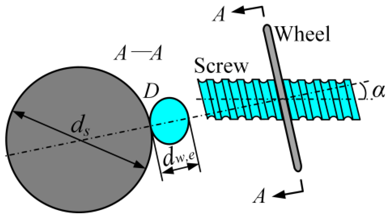
2.2. Grinding Kinematics

Grinding is a complex machining technology with multiple cutting edges. The abrasive grains rotate with the grinding wheel and move linearly relative to the workpiece during the grinding process. From a microscopic point of view, the interaction of multiple abrasive grains on the wheel surface with the workpiece creates the grinding surface topography. The workpiece material in contact with the cutting edge of the grinding wheel is completely removed, and the effects of sliding and plowing are not taken into account during the grinding process. The local coordinate system oxz is created to describe the trajectory of an abrasive grain G1 on the wheel surface, as shown in Figure 1. The origin of the local coordinate system is fixed on the workpiece and coincides with the lowest point of the abrasive grain. Up-grinding is adopted in this paper. The reverse direction of the feed motion of the workpiece is the x-direction, and the direction perpendicular to the feed motion of the workpiece is the z-direction. The trajectory of the abrasive grain G1 is given by the following:
x = v w t + r s sin θ z = r s 1 cos θ
where x and z are the instantaneous coordinates of the movement of the abrasive grain. θ is the rotation angle of the abrasive grain, sin θ = θ, because θ is very small. vw and vs are the feed speed of the workpiece and the circumferential speed of the grinding wheel, respectively. rs is the radius of gyration of the cutting edge of the abrasive grain. t is the time taken for the grain G1 to rotate an angle θ in a counter-clockwise direction from the lowest point, t = rs θ/vs. The trajectory of the abrasive grain G1 is obtained as follows:
z = x 2 2 r 1 1 + v w / v s 2
The workpiece surface is an envelope of the trajectories of all active grains. The subsequent grains pass through the grinding zone, and the residual height on the surface of the workpiece created by the previous grain is removed. The trajectories of all abrasive grains on the surface of the grinding wheel are summarized as follows:
z i , j = x i , j 2 2 r i , j 1 + v w / v s 2
where xi,j and zi,j are the instantaneous coordinates of the ij-th abrasive grain with respect to the local coordinate system, respectively. ri,j is the radial distance from the abrasive grain Gi,j to the center of the grinding wheel. The height of the abrasive grains varies at different positions of the grinding wheel surface, and the distance from the apex of the cutting edge of the abrasive grain to the center of the grinding wheel is represented as follows:
r i , j = r s + h i , j
where the radius of the grinding wheel is rs, and the height of the cutting edge of the abrasive grains on the wheel surface is hi,j. i and j represent the position of the abrasive grain in the circumferential and radial directions on the surface of the grinding wheel.
Schemes for mapping grain trajectories onto the workpiece surface are required for the kinematic-based simulation of the grinding process. The surface topography of the same position results from the combined grinding of several abrasive grains. It is necessary to consider the effect of different abrasive grains at the same position on the workpiece surface. The global coordinate system is established to describe the combined action of multiple abrasive grains between the grinding wheel and the workpiece. The generation principle of the grinding surface is shown in Figure 2, where the highest point of the workpiece surface is set as the origin of the global coordinate system. Assume that the surface topography of the workpiece surface consists of an array of points with different surface heights, as shown in Figure 2. The surface of the workpiece is uniformly discretized into grids, and all grid points form a matrix gm,n. The element g(m, n) of the matrix gm,n represents the height of the point (m,n) on the surface of the workpiece relative to the global coordinate system. The subscripts m and n are the positions of the workpiece surface height g(m,n) in the x and y directions, respectively. In the same way, all grid points on the surface of the grinding wheel are characterized by a matrix hi,j, and element h(i, j) of the matrix hi,j stands for the height of the cutting edge of the abrasive grain at the point (i, j).
To convert the local coordinates into the global coordinates, the distance from the origin o to the origin o’ has to be determined. The trajectory of the first abrasive grain is used as a reference, and the origin of the local coordinate system of the other abrasive grains is shifted to the global coordinate system. The offset distance of the local coordinate system in the x-direction is equal to the movement distance of the workpiece, ΔOi,j = vwt. The arc length of the rotational movement of the abrasive cutting edge is calculated, Li,j = vst. Due to the small spacing of the abrasive grains in the circumferential direction of the grinding wheel, the arc length is approximated as a straight line. Li,j = (i − 1)Δxs. The offset distance of the local coordinate system in the x-direction is obtained as follows:
Δ O i , j = i 1 Δ x s v w / v s
The translation distance of the local coordinate system relative to the global coordinate system in the z-direction is written as follows:
Δ z i , j = a h max h i , j
where a is the grinding depth of the wheel. hmax is the maximum height of the cutting edge of the abrasive grain, hmax = max(hi,j). In the global coordinate system, the trajectories of all the abrasive grains are therefore described as follows:
z i , j = m Δ x w Δ O i , j 2 2 r i , j 1 + v w / v s 2 Δ z i , j
To acquire the grinding surface topography of the workpiece, it is necessary to map the trajectory of all abrasive grains onto the surface of the workpiece according to the grinding kinematics between the trajectory of all abrasive grains and the workpiece. The trajectory of several abrasive grains is recorded at a point (m, n) on the surface of the workpiece, and the trajectory with the lowest point is selected as the final trajectory of the abrasive grains. The final trajectory of the abrasive grains on the workpiece surface is described as follows:
z m , n = min m Δ x w Δ O i , j 2 2 r i , j 1 + v w / v s 2 Δ z i , j
The topography model of the grinding surface is established based on the grinding kinematics of all the abrasive grains. The height matrix of the surface topography model of the workpiece is obtained as follows:
g m , n k = min g m , n k 1 , z m , n
where the subscript k is the surface profile produced by the k-th abrasive grain. To simulate a multi-pass grinding operation, the generated surface is fed back into the programmer as the initial surface texture of the workpiece.

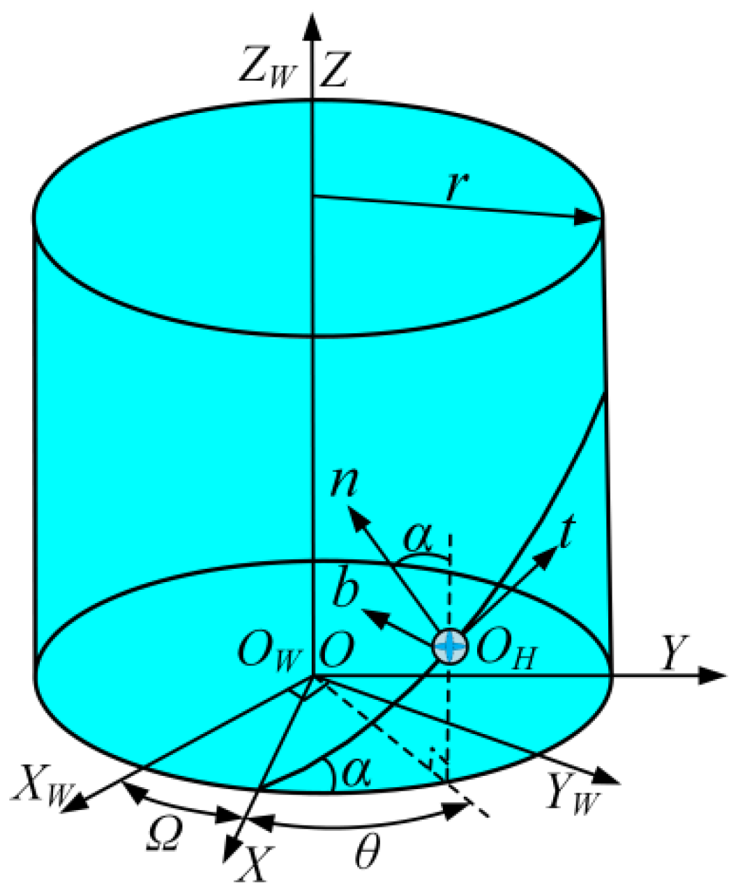
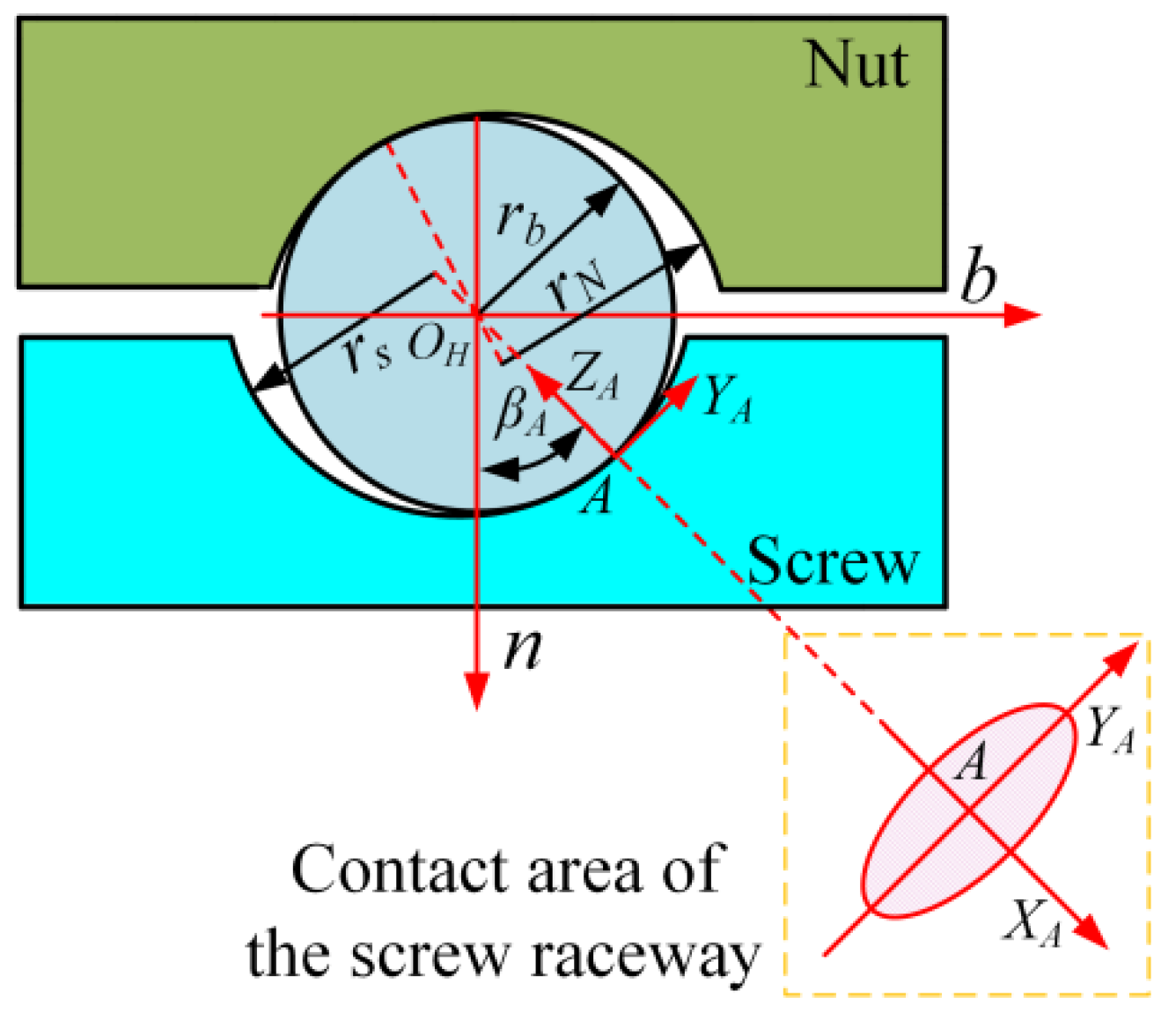
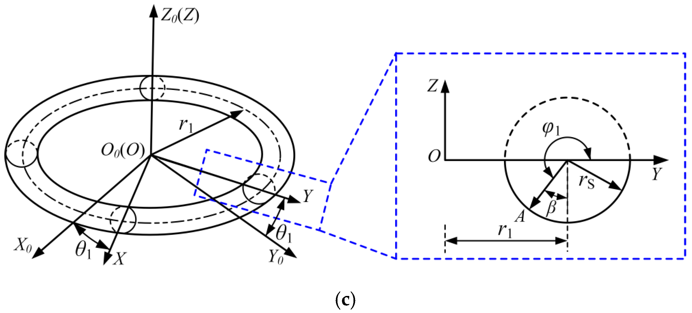
2.3. Modeling of the Geometric Model of the Screw Raceway

The raceway surface of the ball screws is a helical surface with a specific angle, and the angle is numerically equal to the angle α between the grinding wheel axis and the screw axis, as shown in Figure 3. The grinding wheel and screw rotate around their respective spindles, and the screw is fed in the axial direction of the grinding wheel to grind the spiral raceway surface with a circular cross-section.
The speed direction of the screw and the grinding wheel are different at the center of the contact surface between the grinding wheel and the screw. When applying the theory of surface grinding to the grinding of the screw raceway, it is necessary to convert the grinding parameters of the screw and grinding wheel into surface grinding parameters in an equivalent manner.
The A-A plane is perpendicular to the grinding wheel axis and passes through the center D of the contact surface. The equivalent diameters of the grinding wheel and the screw in the A-A plane are expressed as follows:
d s , e = d s , d w , e = d w / cos 2 α
where the diameters of the grinding wheel and the screw are ds and dw. α is the spiral angle of the ball screws. The equivalent velocity of the grinding wheel and the screw at the contact point D is denoted as follows:
v s , e = v s , v w , e = v w cos α
where the speeds of the grinding wheel and the screw are vs and vw, and the equivalent speeds of the grinding wheel and the screw are vs,e and vw,e, respectively. The equivalent diameter of the grinding wheel in the grinding process of the screw is expressed as follows:
d e = d s , e d w , e d s , e + d w , e = d s d w d w + d s cos 2 α
Compared with the raceway of the bearing, the raceway of the ball screws is asymmetric, and the asymmetry of the contact surface of the ball screws increases with the increase in the spiral angle. To accurately construct the grinding surface topography of the screw raceway, it is necessary to establish the geometric model of the screw raceway to describe the geometric features of the screw raceway. The motion relationship between the screw, the raceway, and the nut is taken into account in the construction of the geometric model of the screw raceway. It is, therefore, essential to define the coordinate system of the ball screws, as shown in Figure 4.
The coordinate system OWXWYWZW is used as the inertial reference system, and the ZW axis is consistent with the axis direction of the ball screws. The coordinate system OXYZ is fixedly connected to the screw and rotates with the central axis of the screw. The coordinate system OHtnb is the Frenet–Serret coordinate system. The motion trajectory of the ball center OH is a spiral line, and the position of the origin OH is related to the bottom angle θ of the spiral line. The parameters t, n, and b are the tangent, principal normal, and secondary normal directions of the Frenet–Serret coordinate system.
The geometry of the contact area of the ball screws is determined by the parameters such as the arc radius of the raceway section, the bottom radius of the spiral line, the spiral angle, the ball diameter, and the contact angle. The coordinate system of the contact point A between the ball and the screw raceway is determined to accurately describe the geometric shape of the screw raceway, as shown in Figure 5. The origin A of the coordinate system is the initial contact point between the ball and the screw raceway. In the coordinate system AXAYAZA, the ZA-axis is perpendicular to the tangent plane of the contact point A, the XA-axis is parallel to the tangent direction of the spiral line of the ball center, and the YA-axis direction is determined by the right-hand rule. The parameter equation of the ball surface topography in the contact coordinate system AXAYAZA is expressed as follows:
z k = r b r b 2 x k 2 y k 2 ,   k = A
where A is the contact point between the ball and the screw. The parameter equation of the geometric morphology of the raceway surface is obtained according to the coordinate transformation method in the contact coordinate system AXAYAZA. In the Frenet–Serret coordinate system OHtnb, the parameter expression of the cross-sectional arc of the screw raceway at contact point A is P A S H . The expression of the transformation matrixes is given in Appendix A. The parameter equation of the screw raceway in the coordinate system OXYZ is expressed as P A S S = T S H P A S H , where T S H denotes the coordinate transformation matrix from the coordinate system OXYZ to the Frenet–Serret coordinate system OHtnb of the helical trajectory of the ball center. The coordinate transformation matrix from the Frenet–Serret coordinate system OHtnb to the contact coordinate system AXAYAZA is T H A . The parameter equation of the screw raceway in the AXAYAZA contact coordinate system is established according to the coordinate transformation theory as follows:
P A S A = T S H ( θ C ) T H A 1 P A S S , β A β A 0 β A S β A + β A 0
where T S H (θC) represents the coordinate transformation matrix when θ = θC. θC is the central angle corresponding to the spiral line at the contact point A between the ball and the screw raceway. The geometric morphology of the screw raceway is determined according to the parameter equation of the screw raceway. Substituting the values of parameters θ and βA0 into the parameter equation of the screw raceway in the AXAYAZA contact coordinate system, the geometric morphology of the screw raceway in the contact area is calculated. The structural and grinding parameters of the ball screws are determined according to the product manual [35] and the most common grinding process of the ball screws, as shown in Table 1.
The projection of the three-dimensional geometric morphology of the screw raceway on the plane AXAYA of the contact coordinate system is an irregular rectangular region. Therefore, the two-dimensional interpolation algorithm is used to re-divide the grid, and the interpolation result of the geometric morphology of the screw raceway is obtained, as shown in Figure 6a. The grinding surface topography of the screw raceway is simulated based on the formation mechanism of the grinding surface and the geometric morphology model of the screw raceway. The grinding surface topography of the screw raceway is shown in Figure 6b,c.

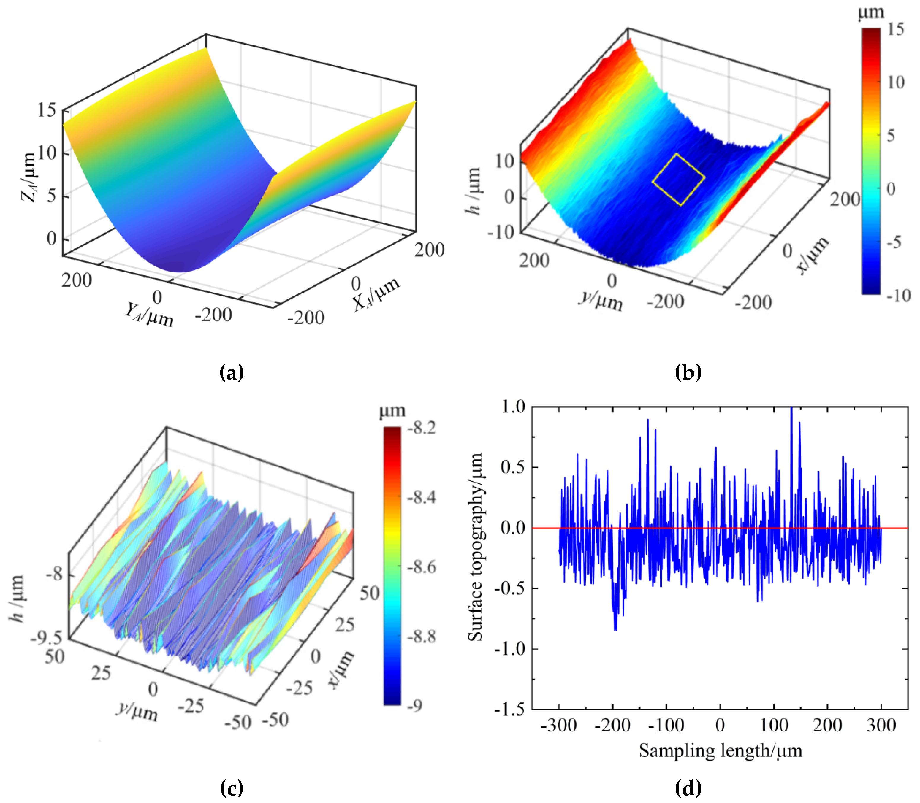
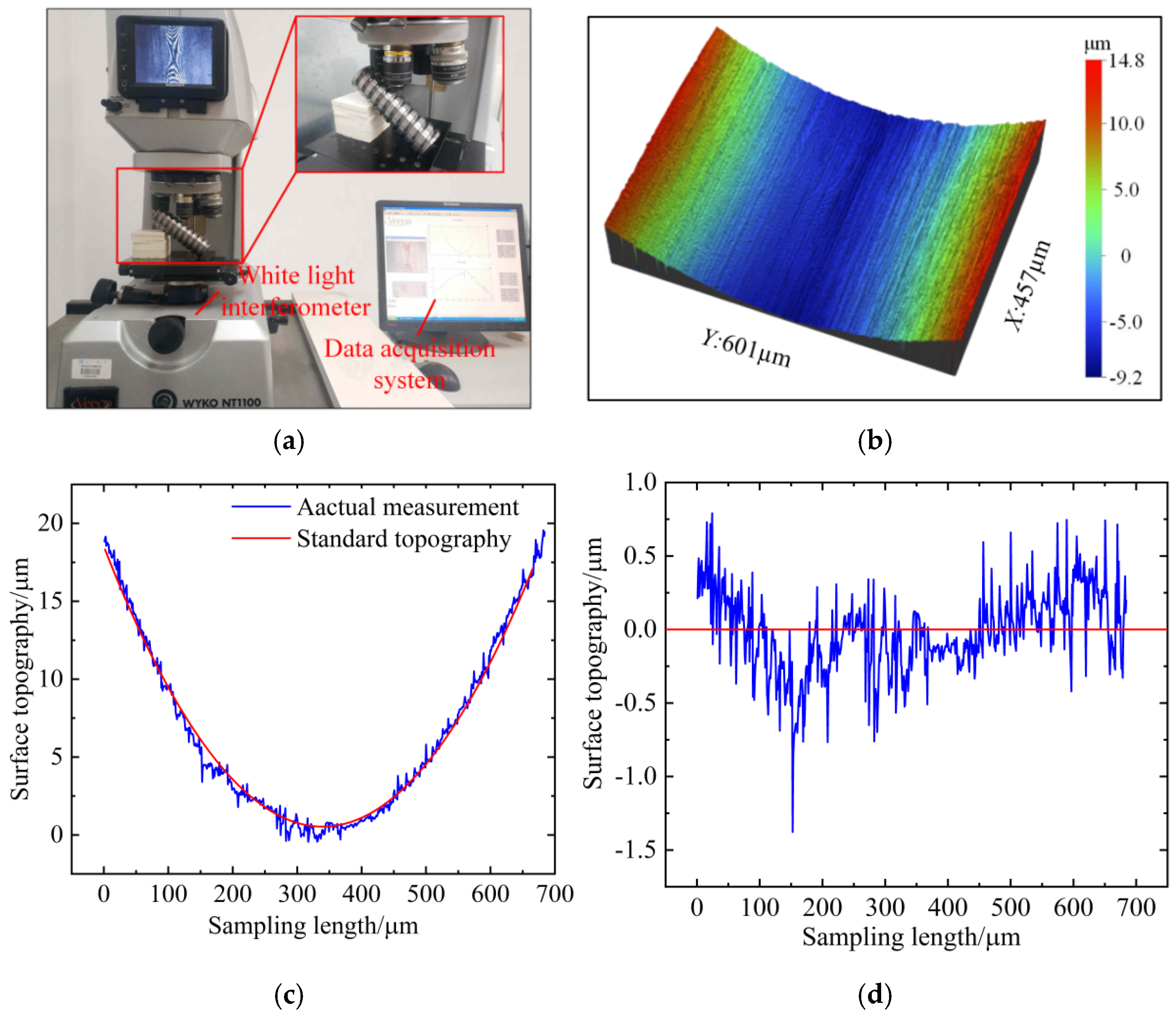
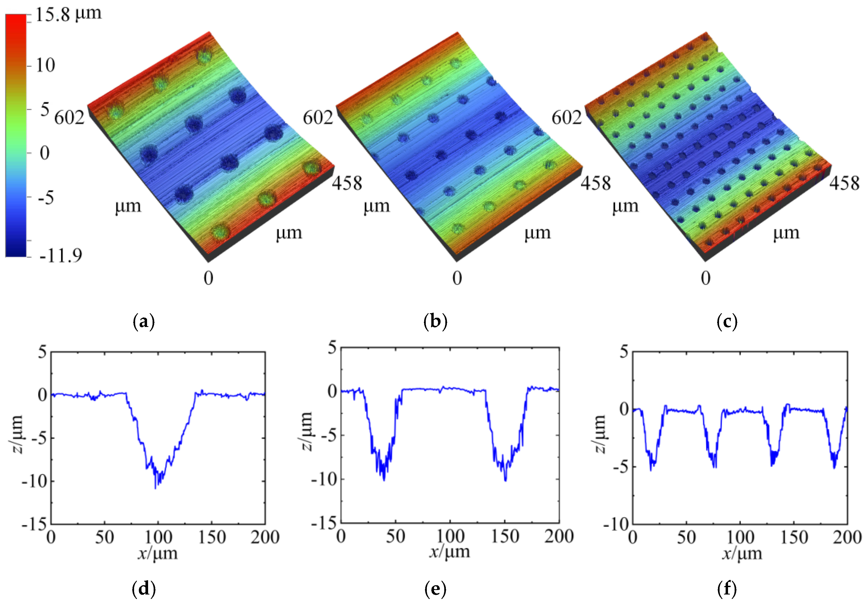
2.4. Measuring the Ground Surface Topography of the Screw Raceway

The ground surface topography of the screw raceway is measured to verify the accuracy of the surface topography model of the screw raceway. It is not possible to directly measure the surface morphology of the entire screw raceway. The DK7735 (Zaozhuang Shenghuan Cnc Machine Co., Ltd., Jinan, China) line cutter is selected to cut and segment the screw. The WYKO-NT1100 white light interferometer (WYKO, Greenback, TN, USA) is used to collect the contour data of the screw raceway. It provides a fast and high-resolution measurement of the surface topography of the screw raceway. The screw specimen is placed on the stage of the instrument to measure the surface topography of the screw raceway. The measurement procedure is shown in Figure 7a, and the three-dimensional surface topography of the measured screw raceway is demonstrated in Figure 7b. The results show that the simulated surface morphology of the screw raceway is similar to the actual measurement, and the grinding texture along the x-direction is visible.
The measured surface topography of the screw raceway is quantitatively analyzed and compared with the simulated surface topography of the screw raceway. The contour of the measured surface morphology of the screw raceway is angle corrected to ensure the positional consistency of the screw specimen on the stage. The profile of the surface topography of the screw raceway after angle correction is shown in Figure 7c. It can be seen that the two-dimensional normal profile of the measured surface topography of the screw raceway is basically consistent with the standard profile of the screw raceway. There is a curvature in the raceway profile of the screw. It is, therefore, necessary to remove the radius from the raceway profile when calculating the surface roughness of the raceway profile. The simulated and measured two-dimensional normal profiles of the surface topography of the screw raceway after radius removal are shown in Figure 6d and Figure 7d, respectively. It can be seen that the surface topography of the screw raceway is generally in the range of −0.5~0.5 μm. The surface roughness of the measured and simulated screw raceways are 0.2128 μm and 0.2072 μm, respectively. The relative error between the simulated and measured surface roughness is only 2.63%, confirming the correctness of the forming mechanism of the grinding surface topography of the screw raceway.

3. The EHL Model of the Textured Raceway of Ball Screws

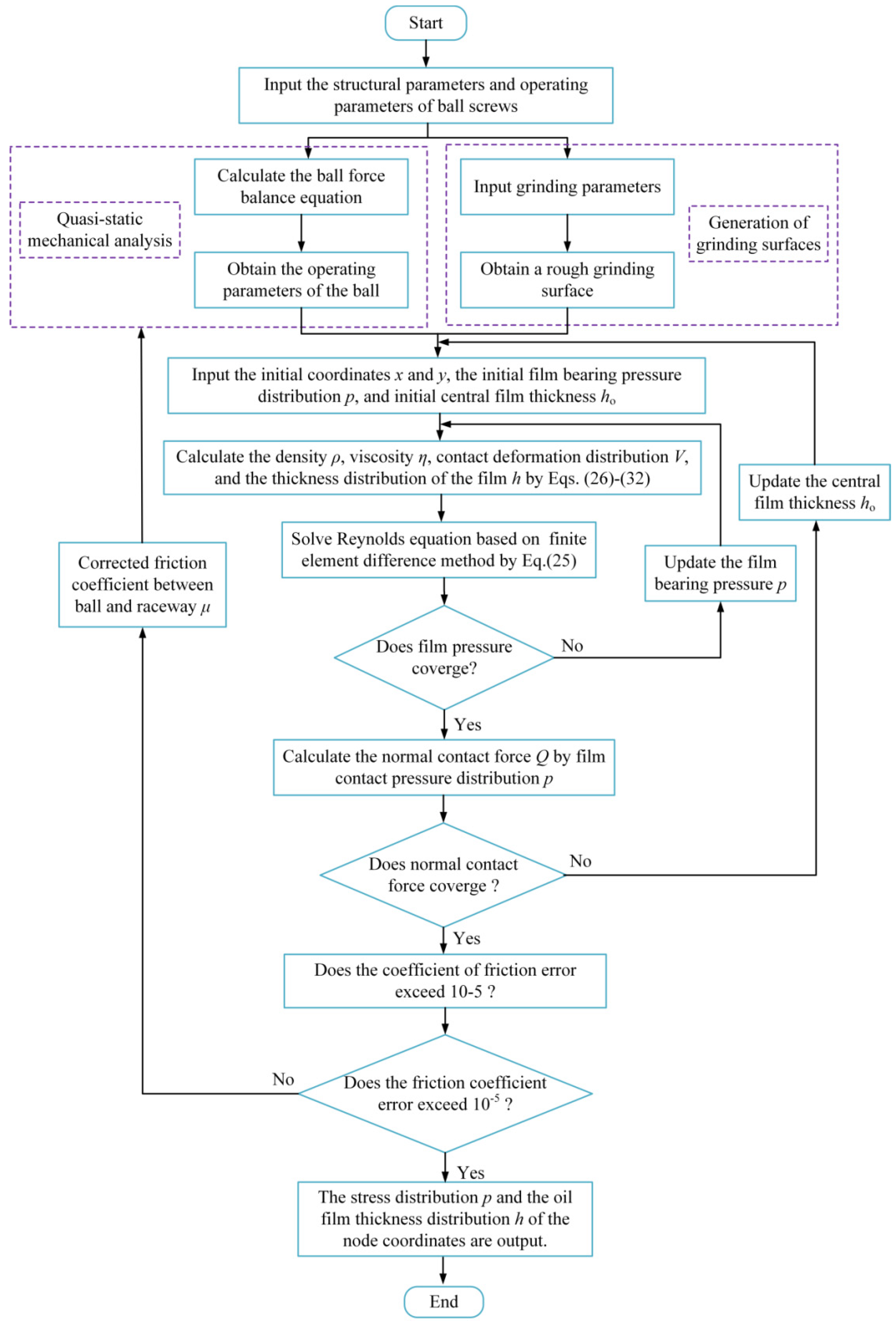
3.1. The EHL Model of the Textured Raceway of Ball Screws

The ball screws usually work in a lubricated state, and the balls, the raceways, and the lubricating oil form an EHL contact system. The pressure distribution and oil film thickness distribution of the lubrication area directly affect the contact state and the friction characteristics of the ball screws under the lubrication conditions. The EHL model of the textured raceway of the ball screws is established based on the ground surface topography of the screw raceway and the geometric features of the textures manufactured on the raceway surface to study the contact properties and friction characteristics under the lubrication conditions.
An elliptical contact area is formed between the ball, the raceway, and the lubricating oil, and the EHL effect is generated in the contact area during the operation of the ball screws, as shown in Figure 8. The contact pressure distribution of the oil film in the contact area and the thickness distribution of the oil film are jointly determined by the structural parameters of the ball screws, the inherent properties of the lubricating oil, and the actual operating conditions of the ball screws. The basic equation for lubrication contact is the two-dimensional Reynolds equation. The Reynolds equation of the EHL of textured raceway of the ball screws is expressed as follows:
x ( ρ h 3 η p x ) + y ( ρ h 3 η p y ) = 6 u 1 + u 2 ( ρ h ) x + 12 ( ρ h ) t
The Reynolds equation only considers the dynamic pressure effect between the ball and the textured raceway of the ball screws to study the EHL characteristics of the textured raceway of ball screws. The basic assumptions of the Reynolds equation are as follows: (a) The contact pair and the lubricating oil are isothermal, ignoring the temperature field of the lubricating oil fluid and the surface temperature of the contact pair. (b) Lubricating oil is a Newtonian fluid that conforms to Newton’s law of viscosity. (c) In the steady state, the viscosity and density of the lubricating oil do not change with the direction of the oil film thickness.
Equation (21) is simplified as follows:
x ρ h 3 η p x + y ρ h 3 η p y = 12 u s ( ρ h ) x
where p is the bearing capacity of the oil film in the contact area, and the initial stress distribution is the non-Hertz contact pressure distribution. h is the oil film thickness distribution in the contact area. ρ and η are the density and viscosity of the lubricating oil, respectively. us is the entrainment speed of the oil film, us = (u1 + u2)/2, u1 and u2 are the linear velocities of the ball and raceway along the tangent direction of the spiral trajectory of the ball center, respectively. x and y are the tangential and normal directions of the spiral trajectory of the ball center, respectively.
A texture micro-unit on the raceway surface of the ball screws is shown in Figure 8. The texture is an ellipsoidal pit texture with a circular cross-section and an elliptical longitudinal section. The radius of the texture is rt, and the maximum depth of the texture is ht. The areal density of the texture on the screw raceway surface is ρt = πrt2/(L/(N − 1))2. The length and width of the entire lubrication contact area are L × L, the number of equidistant grids of the contact area is N × N, and the grid spacing is Δx = Δy. The oil film thickness distribution at the contact point of the textured raceway of the ball screws is characterized as follows:
h ( x , y ) = h o x , y ( x , y ) Ω o ho x , y + h p ( x , y ) ( x , y ) Ω h
h o x , y = h 0 + x 2 2 R x + y 2 2 R y + V x , y + R x , y , ( x , y ) Ω o
where ho and hp are the oil film thickness distribution in the non-textured area and textured area on the raceway surface of the ball screws, respectively. Ωo and Ωh are the oil film bearing area of the non-textured and textured in the elliptical contact area, respectively. h0 is the oil film thickness in the center of the elliptical contact area. Rx and Ry are the equivalent curvature radius in the x and y directions of the contact area, (Ry/Rx)2/3 = b/a. a and b are the semi-major axis and semi-minor axis of the elliptic contact area, respectively. R(x, y) is the rough surface of the grinding raceway according to the grinding surface topography model of the screw raceway mentioned above. V(x, y) is the elastic contact deformation in the elliptical contact area between the ball and the screw raceway. V(x, y) is described as follows:
V x , y = 2 π E Ω p f ( s , t ) + p a ( s , t ) ( x s ) 2 + ( y t ) 2 d s d t
where Ω is the elliptical contact area between the ball and the screw raceway. pa and pf are the bearing stress distribution of the asperity and the oil film in the elliptical contact area, respectively. s and t are additional coordinates of x and y, respectively. The texture is located at the grid center of the contact area, and the mathematical expression of the thickness distribution of the oil film in the texture area is established as follows:
h p ( x , y ) = h t 1 x ( i , j ) / r t 2 y ( i , j ) / r t 2
According to the Roelands’ viscosity formula [36], the viscosity equation of the lubricating oil is expressed as follows:
η = η 0 exp ln η 0 + 9.67 1 + 5.1 × 10 9 p 0.68 1
The density equation of the lubricating oil [37] is indicated as follows:
ρ = ρ 0 1 + 0.6 × 10 9 p 1 + 1.7 × 10 9 p
where ρ0 and η0 indicate the environmental density and environmental viscosity of lubricating oil, respectively. The boundary conditions for the Reynolds equation are denoted as follows:
p ( x i n , y ) = p ( x o u t , y ) = 0 p ( x , y i n ) = p ( x , y o u t ) = 0 p ( x , y ) 0 , ( x i n < x < x o u t ,   y i n < y < y o u t )
where xin and yin are the coordinates at the entrance of the contact area between the ball and the raceway. xout and yout represent the coordinates at the exit of the contact area between the ball and the raceway. The bearing capacity of the oil film in the contact area is equal to the normal contact force of the ball based on the load balancing conditions of the Reynolds equation, and the load balance equation of the Reynolds equation is derived as follows:
Ω p x , y d x d y = Q
The cavitation phenomenon in the oil film area is considered in the process of solving the EHL characteristics of the textured raceway of the ball screws. The boundary conditions of the cavitation phenomenon are introduced when establishing the EHL model of the textured raceway of the ball screws. The Sommerfeld, Half-Sommerfeld, Reynolds, and JFO conditions are the commonly used cavitation conditions at home and abroad, and the Reynolds condition has the advantages of higher prediction accuracy and faster prediction speed. The Reynolds cavitation condition is adopted in the solution of the Reynolds equation of the textured raceway of the ball screws, i.e., p(x,y) = pc if p(x,y) < pc, where pc is the cavitation pressure, pc = 0.03 MPa.
The finite difference method is employed in the solution of the Reynolds equation of the textured raceway of the ball screws. The iterative calculation process of the Reynolds equation of the EHL characteristics of the textured raceway of the ball screws is shown in Figure 9.

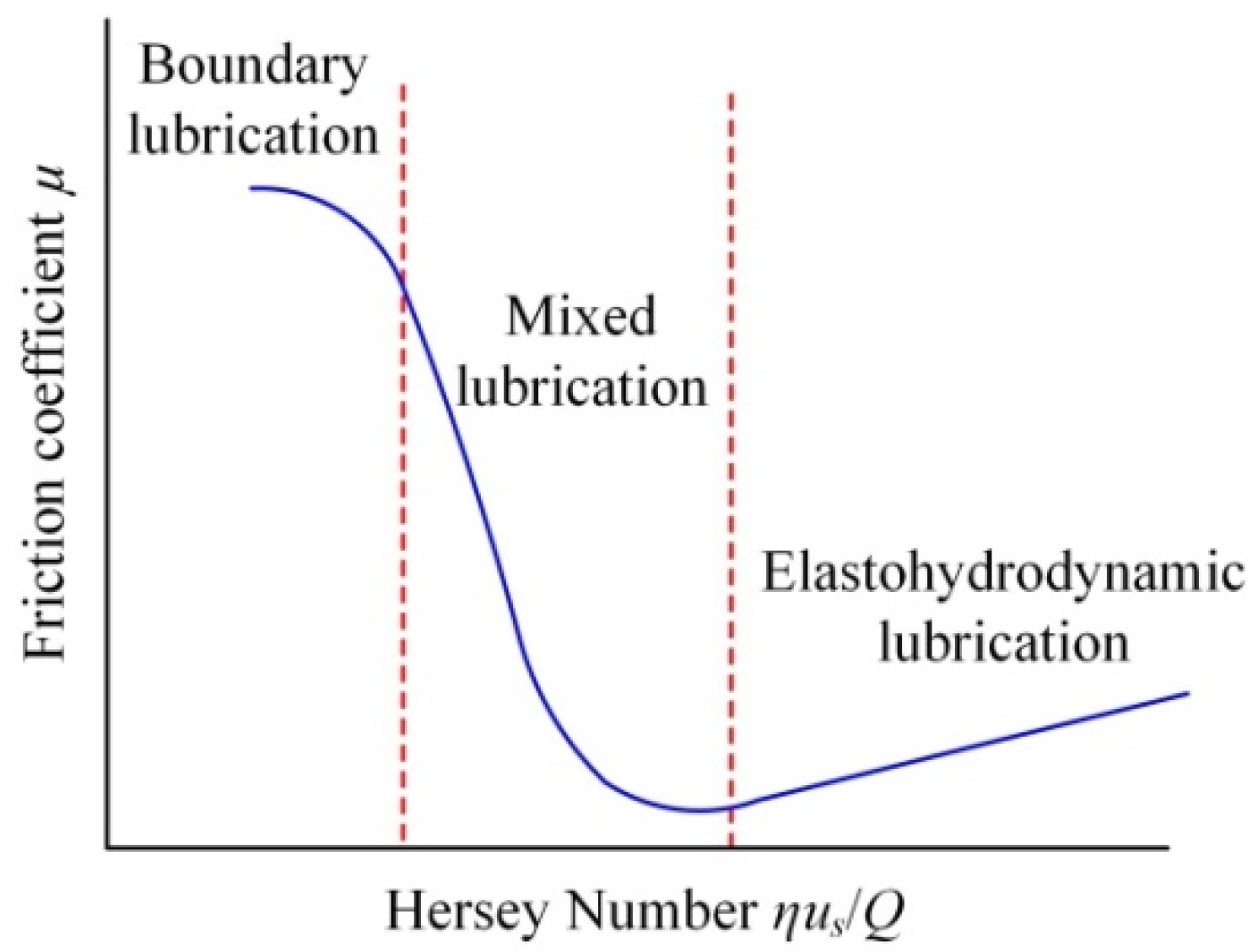
3.2. Calculation of Friction Coefficient and Friction Torque

Stribeck conducted a large number of friction experiments on rolling bearings to obtain the Stribeck friction characteristic curve, and lubrication is divided into three stages: boundary lubrication, mixed lubrication, and EHL, as shown in Figure 10. The Stribeck friction characteristic curve describes the relationship between the friction coefficient and the friction characteristic parameters such as the motion speed, the viscosity of the lubricating oil, and the normal contact force. The raceway contact surface of the contact system is rough and uneven, as shown in Figure 6b and Figure 7b. The contact area is divided into the asperity contact area and the EHL contact area, and the load is shared by two areas, as shown in Figure 11.
The lubrication state of the contact system of the ball screws is distinguished by the film thickness ratio Λ = hmin/Rq under different working conditions of the ball screws, where hmin is the minimum oil film thickness of the contact area between the ball and the screw raceway. Rq is the root mean square of the roughness of the screw raceway, Rq = 0.05 µm. The friction coefficient of the contact system of the ball screws is the accumulation of the contact friction coefficient of the asperity and the shear friction coefficient of the oil film. The friction coefficient of the asperity contact areas between the ball and screw raceway is expressed as follows:
f a = μ a Q a / Q
where Q is the total normal contact force of the ball, and Qa represents the normal force of the asperity contact. μa is the static friction coefficient of the raceway surface, μa = 0.12. The Ree-Eyring constitutive equation describes the relationship between the shear force and the shear strain rate of the oil film in the contact area between the ball and screw raceway. The shear strain rate of the lubricating oil film is expressed as follows:
γ ˙ = τ 0 η 0 sinh τ τ 0
The entrainment speed of the oil film in the normal direction of the raceway spiral is much smaller than that in the tangential direction. The shear strain rate of the oil film in the normal direction of the raceway spiral is neglected, and the shear strain rate is obtained according to the force balance of the asperity in the contact area as follows:
γ ˙ = h 2 η p x + Δ u h
Combining Equations (37) and (38), the shear force distribution of the oil film in the grid of the contact area is written as follows:
τ i , j = τ 0 arcsinh η 0 h i , j 2 η i , j τ 0 p i , j x i , j + η 0 Δ u i , j τ 0 h i , j
The shear friction coefficient of the oil film in the contact area between the ball and the screw raceway is calculated as follows:
f o = A τ i , j d A i , j / Q
where τ and τ0 are the shear stress and the characteristic shear stress of the lubricating oil film. A is the contact area of the lubricating oil film. The friction coefficient and friction force between the ball and the raceway are determined as μ = fa + fo and Fs = μ Q, respectively. Equations (27)–(31) are used to solve the friction coefficient of the contact area between the ball and the textured raceway. The friction torque of the ball screws is mainly composed of the friction torque between the ball and the screw raceway and the friction torque between the ball and the nut raceway, and the friction torque of the ball screws is expressed as follows:
M S = n b F S A L A cos λ + n b F S B L B cos λ
where nb is the number of working balls in a nut. LA and LB are the friction arms of the screw and the nut raceway, respectively. FSA and FSB are the friction force between the ball and the screw raceway, and the nut raceway. The contact area between the ball and the raceway is smaller than the radius of the ball, and the contact point is considered to be the center of the contact area. The vertical distance from the contact points A and B to the axis of the screw, that is, the friction arm of the raceway, is expressed approximately as follows:
L A = ( r r b cos β A ) , L B = ( r + r b cos β B )

4. Analysis of Anti-Friction Characteristics of Textured Raceway of the Ball Screws

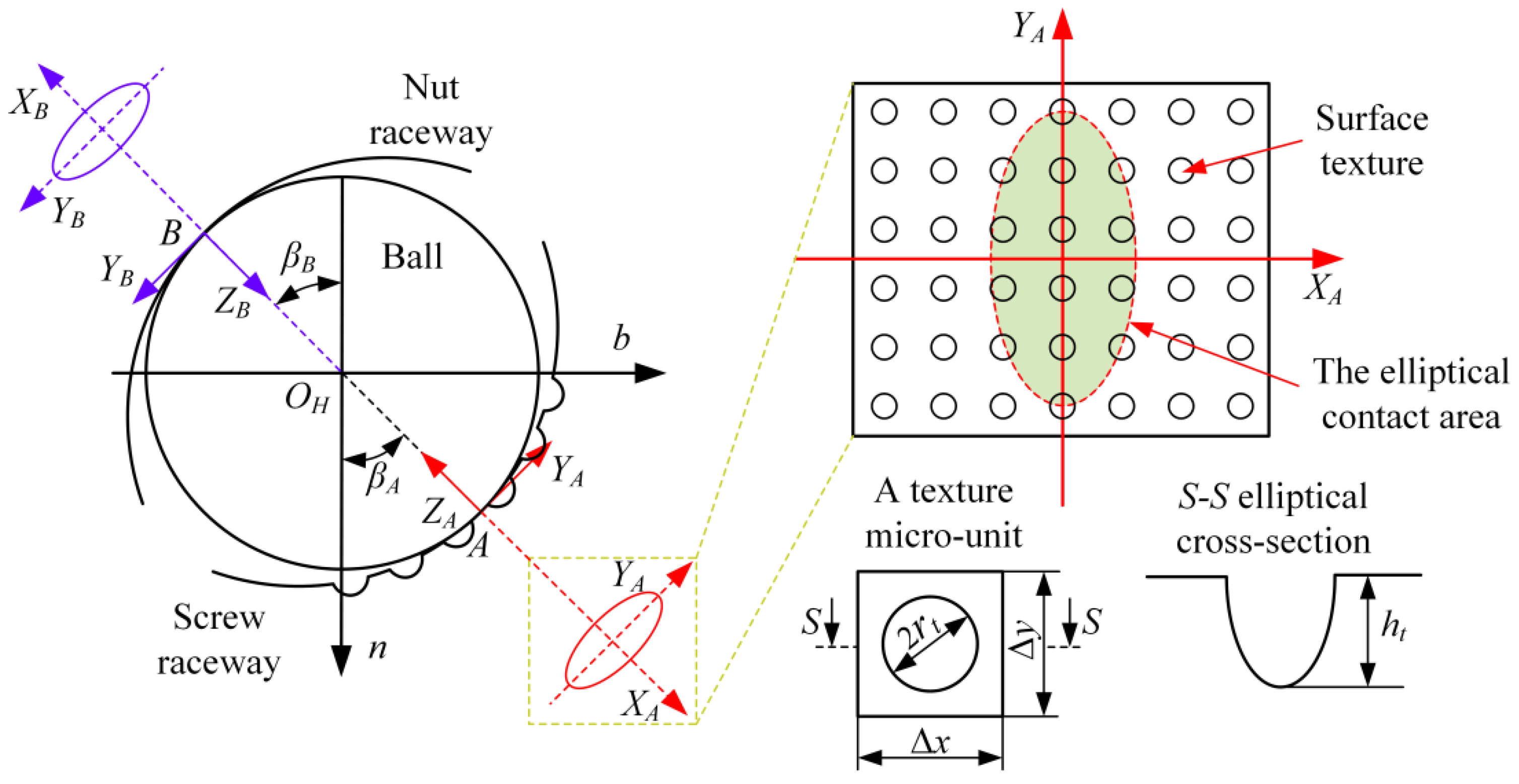
4.1. The Geometric Features of the Textures

It can be seen from Equations (23)–(26) that the oil film thickness distribution of the textured raceway of the ball screws is jointly determined by the working conditions, the surface topography of the elliptical contact area, the geometric features of the manufactured textures, and the elastohydrodynamic properties of lubricating oil. The operating conditions include the rotational speed and axial load of the ball screws, corresponding to the entrainment speed of the oil film and the normal contact force of the ball in the elliptic contact area. The surface topography of the elliptical contact area contains the curvature surface of the ball and raceway and the rough grinding surface of the screw raceway. The geometric features parameters of the manufactured texture include diameter, depth, and areal density. The elastohydrodynamic characteristics of lubricating oil involve the bearing capacity, thickness, viscosity, and density of lubricating oil film.
The geometric feature parameters of different textures are designed to facilitate the study of the EHL characteristics of textured raceways of the ball screws under different axial loads and rotation speeds of the ball screws. The geometric feature parameters of the textures are defined as the diameter of the texture dt, the depth of the texture ht, and the areal density of the texture ρt, according to the single-factor analysis method, as shown in Table 2. The raceway surface without the textures is used as a control group simultaneously.

4.2. Analysis of EHL Characteristics of Textured Raceway of the Ball Screws

To investigate the EHL characteristics of the lubricating oil film of the textured raceway of the ball screws under the oil-rich condition. Following the EHL model established and the geometric feature parameters of the textures, the preload force is 1500N, the entrainment speed is 83 mm/s, the texture diameter dt = 10 μm, the texture depth ht = 5 μm, the area density ρt = 6%, and the bearing stress distribution and thickness distribution of the oil film at the contact point of the textured raceway are obtained as shown in Figure 12. It can be observed from Figure 12a that the bearing stress distribution of the oil film in the contact area is no longer a smooth surface but a rough and uneven surface, taking into account the ground surface topography of the raceway and the geometric features of the textures manufactured on the raceway surface. The oil film thickness distribution in the textured area of the screw raceway is significantly increased, reducing the direct contact of the asperities in the contact area, as shown in Figure 12b.
The working ball is repeatedly rolling and sliding in the textured raceway of the ball screws under steady-state conditions. It is essential to investigate the impact of varying the positions of the texture within the elliptical contact area of the screw raceway on the EHL characteristics of the oil film. The surface texture is located at the inlet, center, and outlet of the contact area between the ball and screw raceway, and the EHL characteristics of the oil film are solved based on the established EHL model of the textured raceway of the ball screws. The two-dimensional distribution of the bearing stress and oil film thickness and the contour map of the bearing stress of the oil film are presented in Figure 13.
The ball screw of the textured raceways is in a state of mixed lubrication. The balls are in direct contact with the rough raceway surface in the contact area of the asperity, resulting in the wear of the textured raceway. In addition, it can be seen from Figure 13 that the viscous lubricating oil flows through the texture area of the raceway surface, and the oil film produces a dynamic pressure effect that reduces the friction coefficient of the ball screws, achieving the effect of reducing friction and anti-wear. The friction coefficient is used as the design objective for textured raceways of the ball screws, and the anti-friction characteristics of ball screws are investigated under different axial loads and rotation speeds and geometric features of the manufactured textures. To reduce the calculation error, the friction coefficient of the textured raceway of the ball screws is averaged when the texture is located at the inlet, center, and outlet of the contact area, respectively.

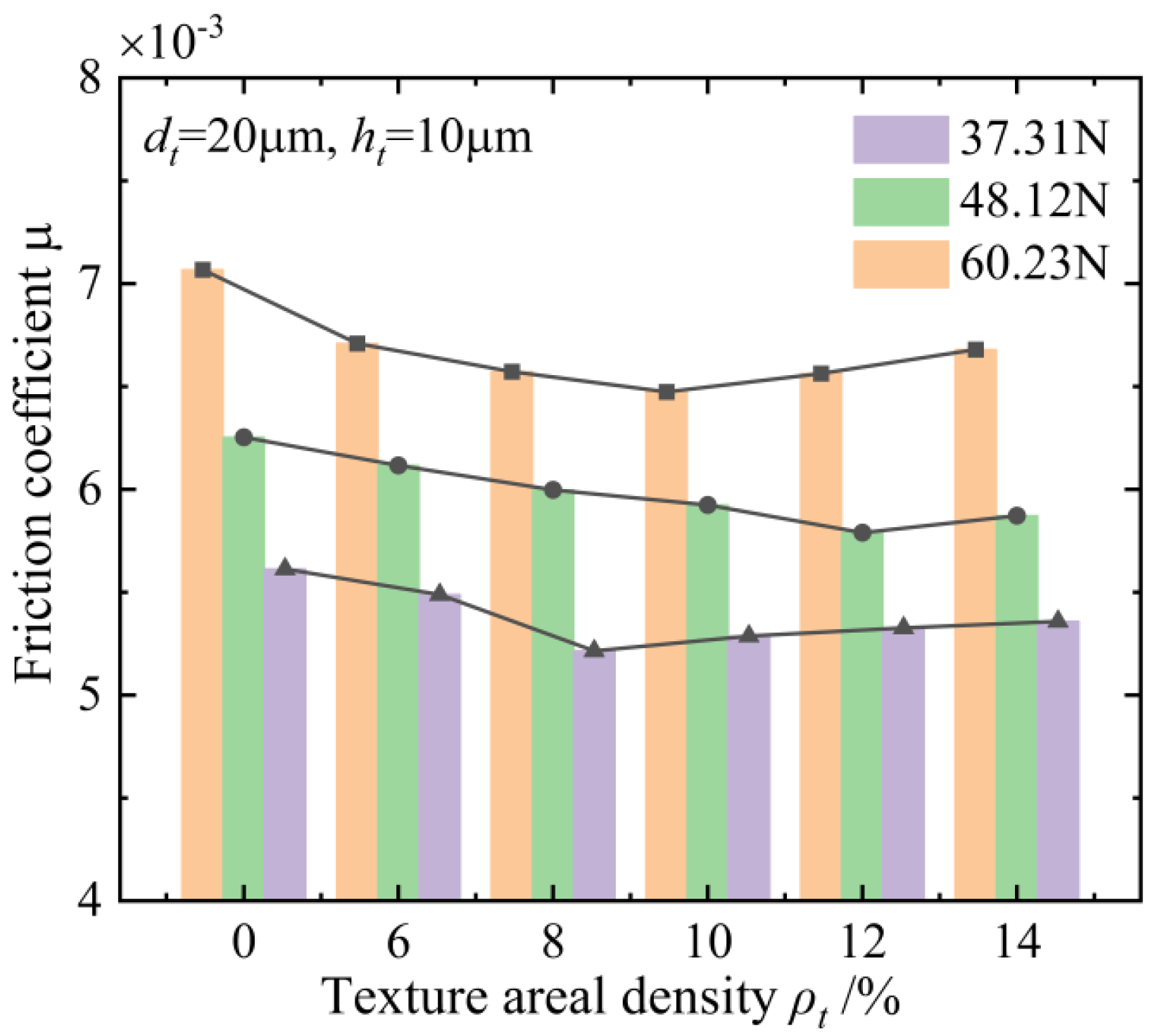
4.3. Influence of the Axial Loads on the Anti-Friction Characteristics of the Textured Raceway of the Ball Screws

The friction coefficient is composed of the contact friction coefficient of the asperity and the shear friction coefficient of the oil film between the ball and the textured raceway. The range of the friction coefficient of the ball screws is 0.003–0.01 in the THK product manuals. The normal contact force between the ball and the textured raceway is determined by the axial loads of the ball screws. To investigate the influence of the axial loads of the ball screws on the EHL characteristics of textured raceways with different geometrical features of the textures. The working conditions of the ball screws are determined as follows: the rotation speed of the ball screws is 100 r/min, that is, the entrainment speed of the oil film us = 167.5 m/s; the preload force of the ball screws is 1500N; the axial loads of the ball screws are 1000N, 2000N, and 3000N, and the corresponding normal contact forces are 37.31N, 48.12N, and 60.23N, respectively.
The variation trend of the friction coefficient with the texture diameter (workpiece#1) is illustrated in Figure 14 under the action of three different axial loads. Figure 14 demonstrates that the variation trend of the friction coefficient between the ball and the textured raceway is the same under three different axial loads, and the friction coefficient initially decreases and then slowly increases with the change in the texture diameter. The friction coefficient of the textured raceway of the ball screws is lower than that of the non-textured raceway, indicating that the textured raceway of the ball screws has an anti-friction effect.
Furthermore, the higher the axial load is subjected to the ball screws, the more obvious the changes in the dynamic pressure effect and the anti-friction effect of the textured raceway of the ball screws with the texture diameter. With the increase in the axial load of the ball screws gradually, the average thickness of the oil film between the ball and the rough surface of the screw raceway gradually decreases, and the bearing area of the asperity gradually increases, resulting in the friction coefficient of the textured raceway of the ball screws increases. The textured raceway of the ball screws provides an anti-friction effect, and the friction coefficient of the contact system of the ball screws is reduced by 15.2% under the axial load of 3000 N, and the texture diameter is 40 μm.
Figure 15 displays the variation trend of the friction coefficient with the texture depth under three axial loads (workpiece#2). It can be seen from Figure 15 that the friction coefficient between the ball and the textured raceway of the ball screws is lower than that of the non-textured raceway of the ball screws under the three axial loads, indicating that the textured raceways have the effect of reducing friction. The ball screw is in a mixed lubrication state, and the oil film thickness is very thin under the condition of the entrainment speed us = 167.5 m/s. The shear friction coefficient of the oil film is a small proportion of the total friction coefficient. The friction coefficient under three axial loads does not change significantly with increasing texture depth. The average thickness of the oil film gradually decreases with increasing normal contact force, the bearing contact area of the asperity gradually increases, and then the friction coefficient of the textured raceway gradually increases. When the axial load of the ball screws is 3000 N, and the texture depth is 10 µm, the textured raceway of the ball screws exhibits optimum friction-reducing effects, and the friction coefficient of the textured raceway is reduced by 7.6%.
The variation trend of the friction coefficient with the areal density of the texture (workpiece#3) is shown in Figure 16. Figure 16 illustrates that the friction coefficient between the ball and the textured raceway decreases initially and subsequently increases with the change in the areal density under the three axial loads. It is interesting to note that the friction coefficient of the textured raceway is lower than that of the non-textured raceway, and the textured raceway of the ball screws provides an anti-friction effect. The higher the axial load of the ball screws, the higher the proportion of the contact area of asperity, and the friction coefficient of the texture raceway of the ball screws is increased. The textured raceway of the ball screws achieves the best friction reduction effect when the axial load of the ball screw is 1000 N, the areal density of the texture is 8%, and the friction coefficient is reduced by 8.3%.

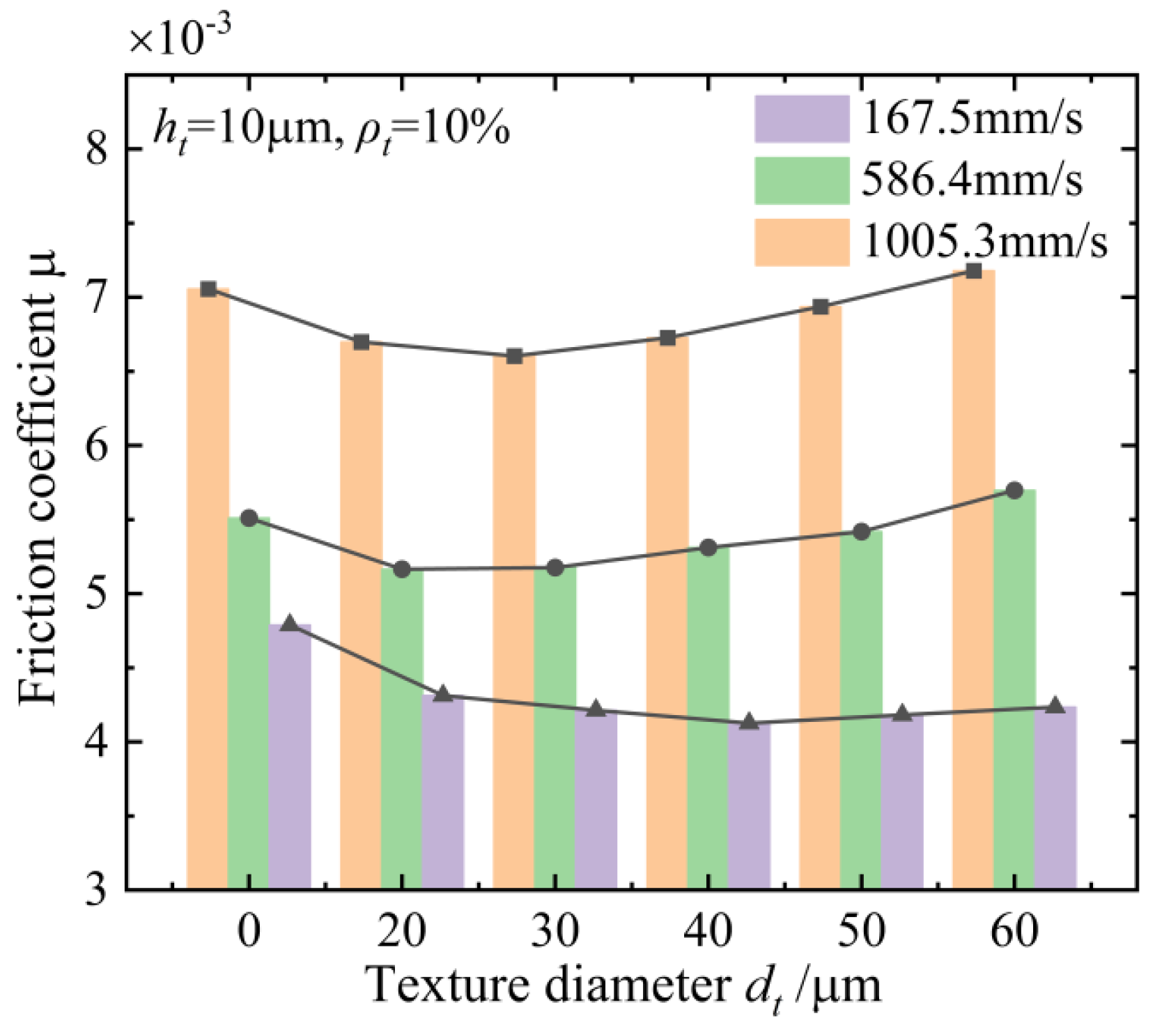
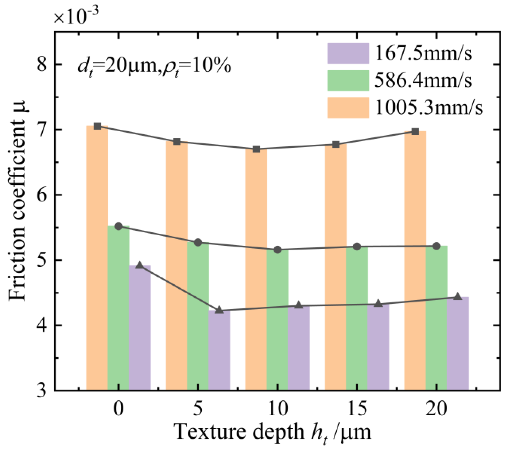
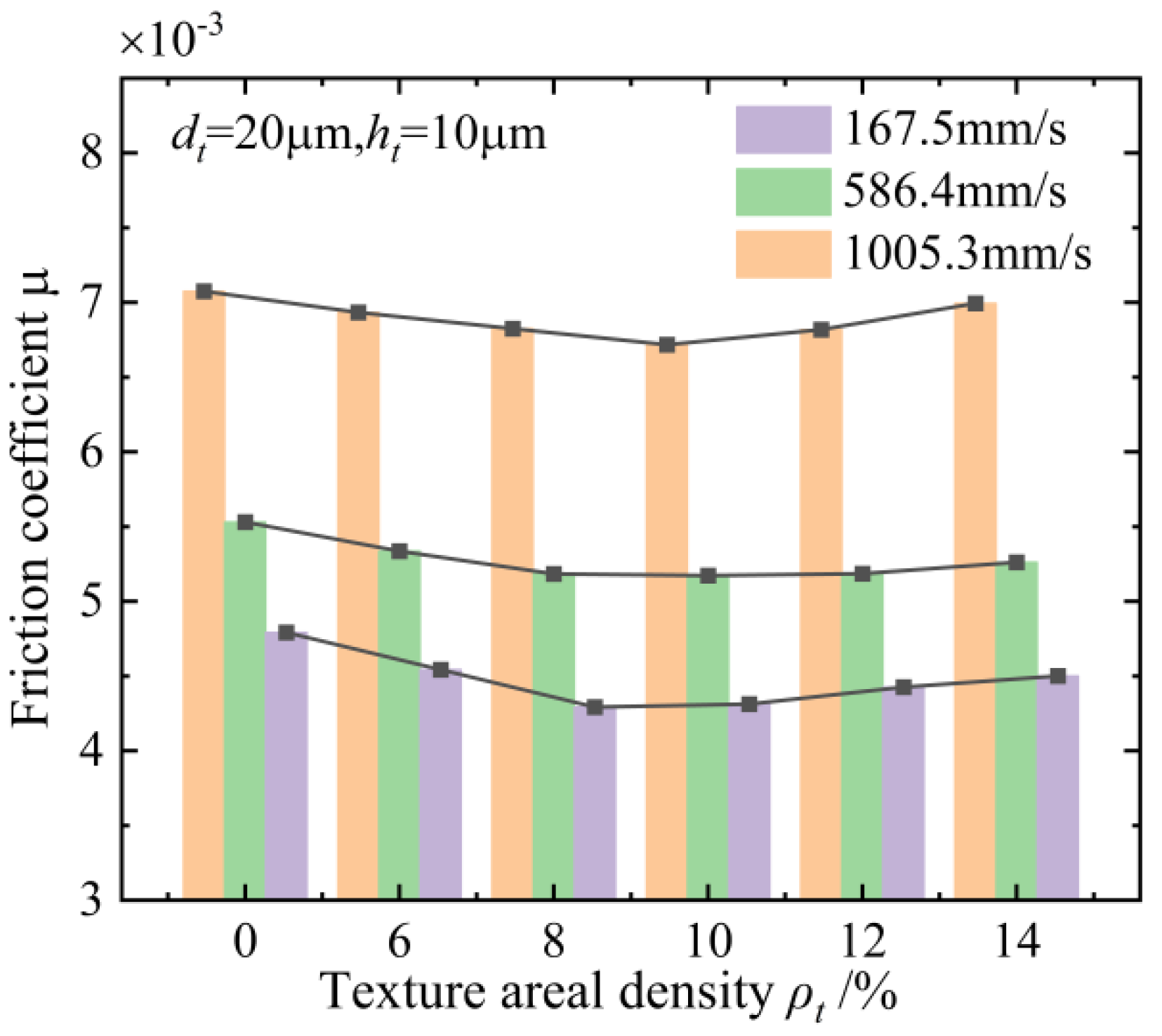
4.4. Influence of the Rotation Speeds on the Anti-Friction Characteristics of the Textured Raceway of the Ball Screws

The rotation speed of the ball screws determines the entrainment speeds of the oil film in the contact area. To investigate the influence of the rotation speeds of the ball screws on the EHL characteristics of textured raceways with different geometrical features of the textures, the ball screw is only subject to the preload force. That is, the normal contact force of the ball is 27.6N. The rotation speeds of the ball screws are 100 r/min, 350 r/min, and 600 r/min, and the corresponding entrainment speeds of the oil film between the ball and textured raceway are 167.5 mm/s, 586.4 mm/s, and 1005.3 mm/s. The variation trends of the friction coefficient between the ball and the textured raceway with geometric features of the texture are investigated under three different rotation speeds of the ball screws.
The relationship between the friction coefficient and the texture diameter is illustrated in Figure 17 under three different rotation speeds (workpiece#1). Figure 17 indicates that the friction coefficient initially decreases and then increases with increasing texture diameter under three different rotation speeds of the ball screws. The friction coefficient of the textured raceway is smaller than that of the non-textured raceway, indicating that the textured raceway has an anti-friction effect. The ball screw is in a mixed lubrication state, the oil film thickness is thin, and the contact friction coefficient of the asperity accounts for a large proportion of the total friction coefficient. The surface texture reduces the contact area of the asperity in the elliptical contact area, thereby reducing the contact friction coefficient of the asperity.
The friction coefficient of the textured raceway of the ball screw is higher than that of the non-textured raceway when the texture diameter is 60 μm, and the rotation speeds of the screw are 350 r/min, and 600 r/min, suggesting that the inappropriate geometric feature parameters of the texture increase the friction of the ball screws. The lubrication condition of the ball screw is good at medium and high rotation speeds, and the friction force is mainly the shear friction force of the oil film. The ball screw is in the EHL state, the oil film thickness between the ball and the raceway is thick, and the asperity on the rough raceway surface is completely covered. The friction coefficient is mainly composed of the shear friction coefficient of the oil film, and the textured raceway of the ball screws further increases the oil film thickness, resulting in a higher friction coefficient. The friction-reducing effect of the textured raceway is optimum when the rotation speed of the screw is 100r/min, and the textured diameter is 40 µm, and the friction coefficient is reduced by 13.8%.
The variation trend between the friction coefficient of the textured raceway of the ball screws and the texture depth is shown in Figure 18 under three different rotation speeds (workpiece#2). The friction coefficient reaches the minimum when the rotation speed is 100 r/min, the texture depth is 5 μm, and the friction coefficient increases slightly as the texture depth increases. The proportion of direct contact with the asperity is relatively large when the rotation speed of the ball screws is low, and the proportion of direct contact with the asperity decreases after the screw raceway is textured.
The friction coefficient of the textured raceway achieves the minimum at an entrainment speed of 586.4 mm/s and a texture depth of 10 µm, the proportion of direct contact with the asperity is relatively low, and the dynamic pressure effect in the contact area is enhanced after the screw raceway is textured. With the further increase in the texture depth, the lubricating oil in the surface texture produces a serious backflow phenomenon, and the friction coefficient of the textured raceway increases. The optimal friction reduction effect is obtained at an entrainment speed of 167.5 mm/s and a texture depth of 5 μm, and the friction coefficient is decreased by 13.9%.
The changing trend of the friction coefficient with the areal density of the texture is presented in Figure 19 under three different rotation speeds of the screw (workpiece#3). The thickness of the lubricating oil film is thin, and the proportion of direct contact with the asperity is higher when the rotation speed of the screw is 100 r/min. The proportion of direct contact with the asperity is reduced, and the friction coefficient decreases after the surface texture is applied to the raceway surface of the ball screw. The entrainment speeds of the oil film are 586.4 mm/s and 1005.3 mm/s, and the friction coefficient of the textured raceway increases with the increase in the areal density of the texture. The ball screw is in good lubrication condition at the medium and high rotation speeds of the ball screw. The friction force mainly comes from the shearing force of the oil film, and the surface texture increases the thickness of the oil film in the contact area, increasing the friction coefficient. The optimum friction reduction is achieved when the entrainment speed is 167.5 mm/s, the areal density of the texture is 8%, and the friction coefficient is reduced by 10.2%.
The micro-hydrodynamic pressure perturbations effect is caused by the textured surface of ball screws with appropriate geometric parameters according to the analysis of the anti-friction characteristics of the textured surface. The micro-hydrodynamic pressure perturbations effect of the ball screws enhances the thickness of the oil film and reduces the contact friction between the ball and the raceway of the contact area under different working conditions. The surface texture with different geometric parameters and distributions optimize the lubrication state of the ball screws, thereby reducing the friction coefficient.

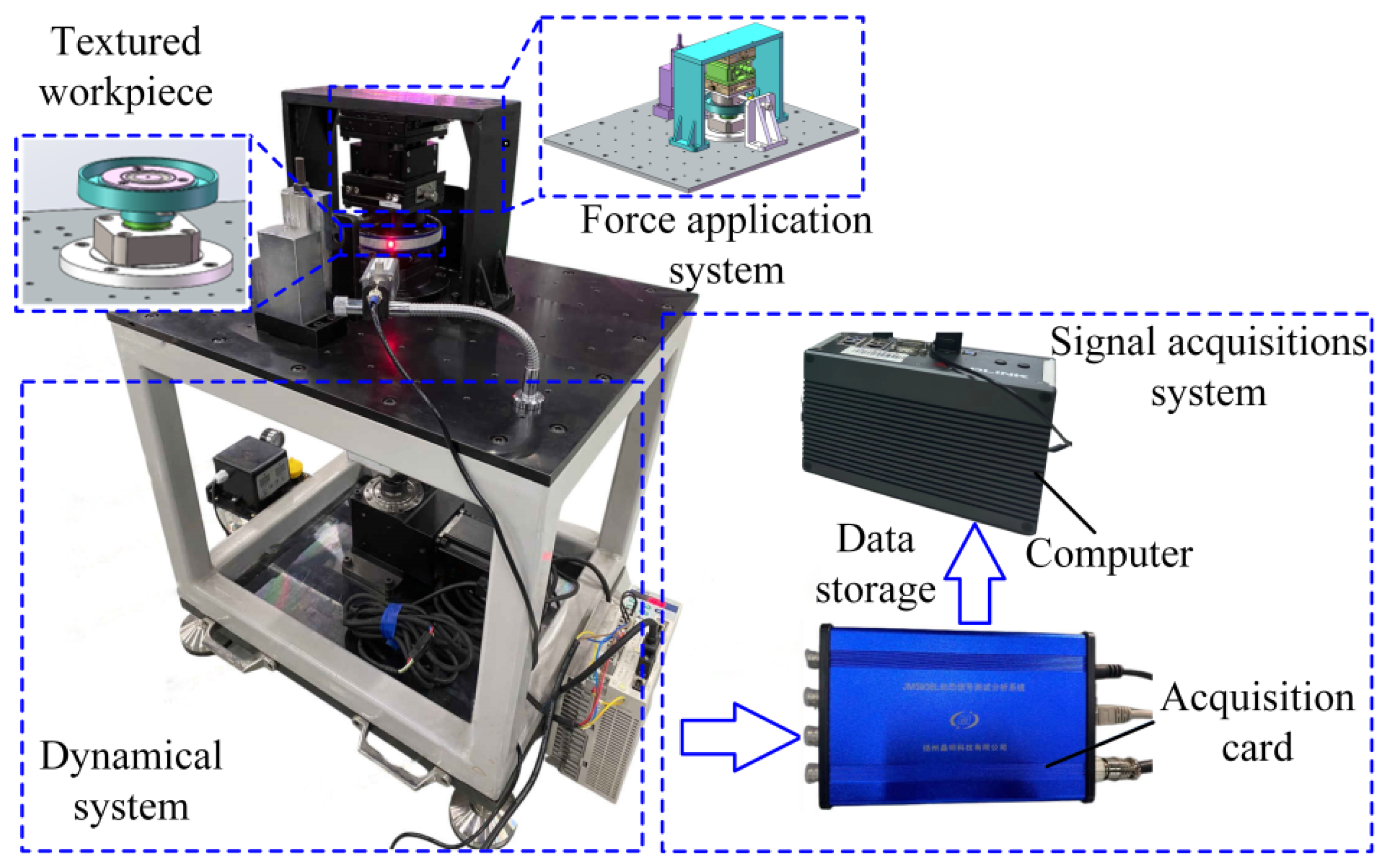
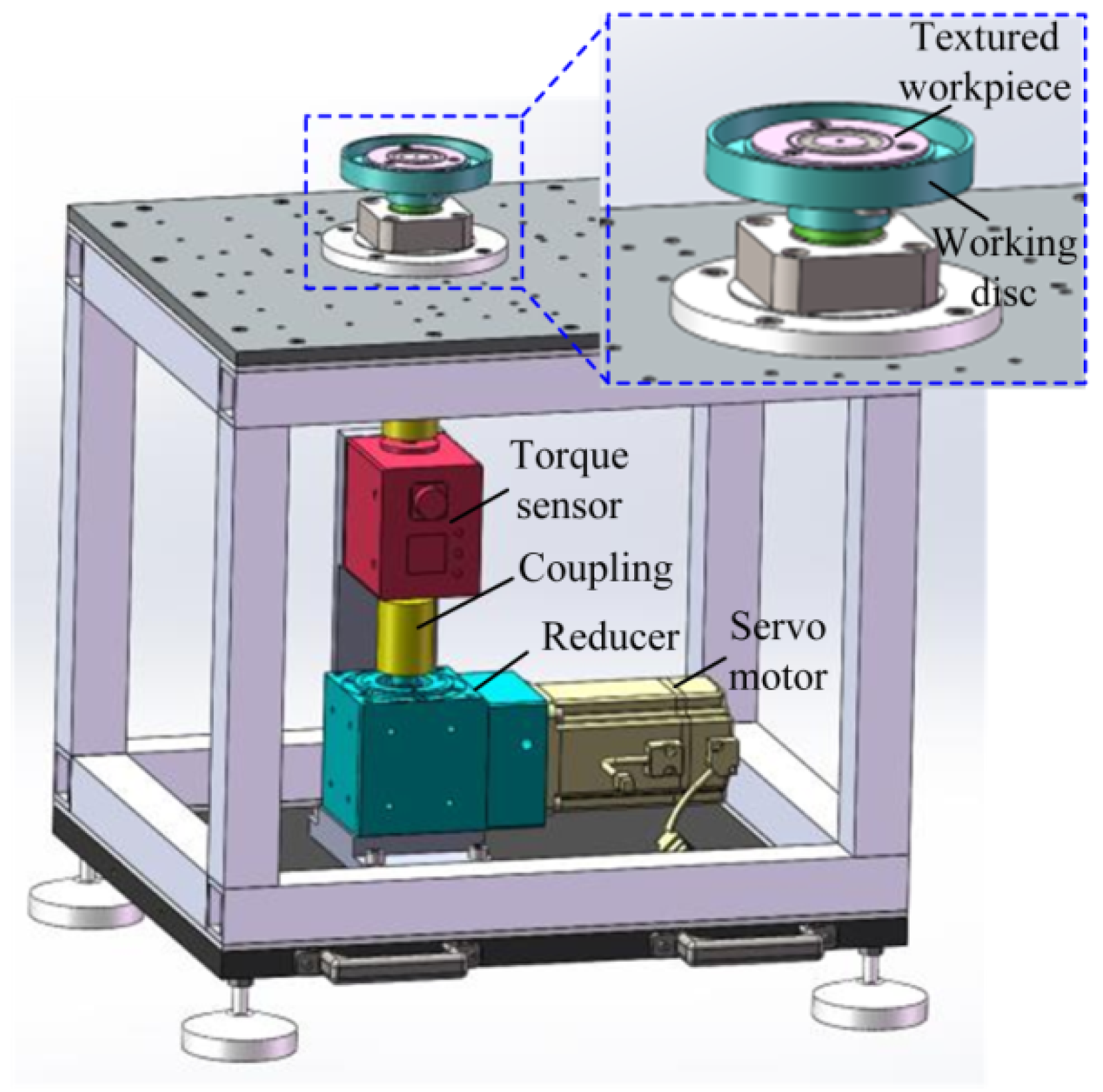
5. The Proof-of-Principle Experiments of the Textured Raceway of the Ball Screws

To quickly reflect the friction-reducing properties of the EHL of the textured raceway of the ball screws with different geometric features under different axial loads and rotation speeds of the ball screws, the proof-of-principle experiments of the friction reduction performance of the textured raceway of the ball screws are conducted based on the equivalent substitution method. The equivalent substitution method ensures that the principal curvature of the spiral raceway and circular raceways are the same, guaranteeing the contact characteristics of the ball screws in the oil-rich state. The ball/raceway friction and wear test bench is designed and constructed to simulate the actual contact state between the ball screw and the raceway of the ball screws and verify the effectiveness of the textured raceway of the ball screws. The ball/raceway friction and wear test bench mainly includes the textured workpieces, the force application system, the dynamical system, and the signal acquisition system, as shown in Figure 20.

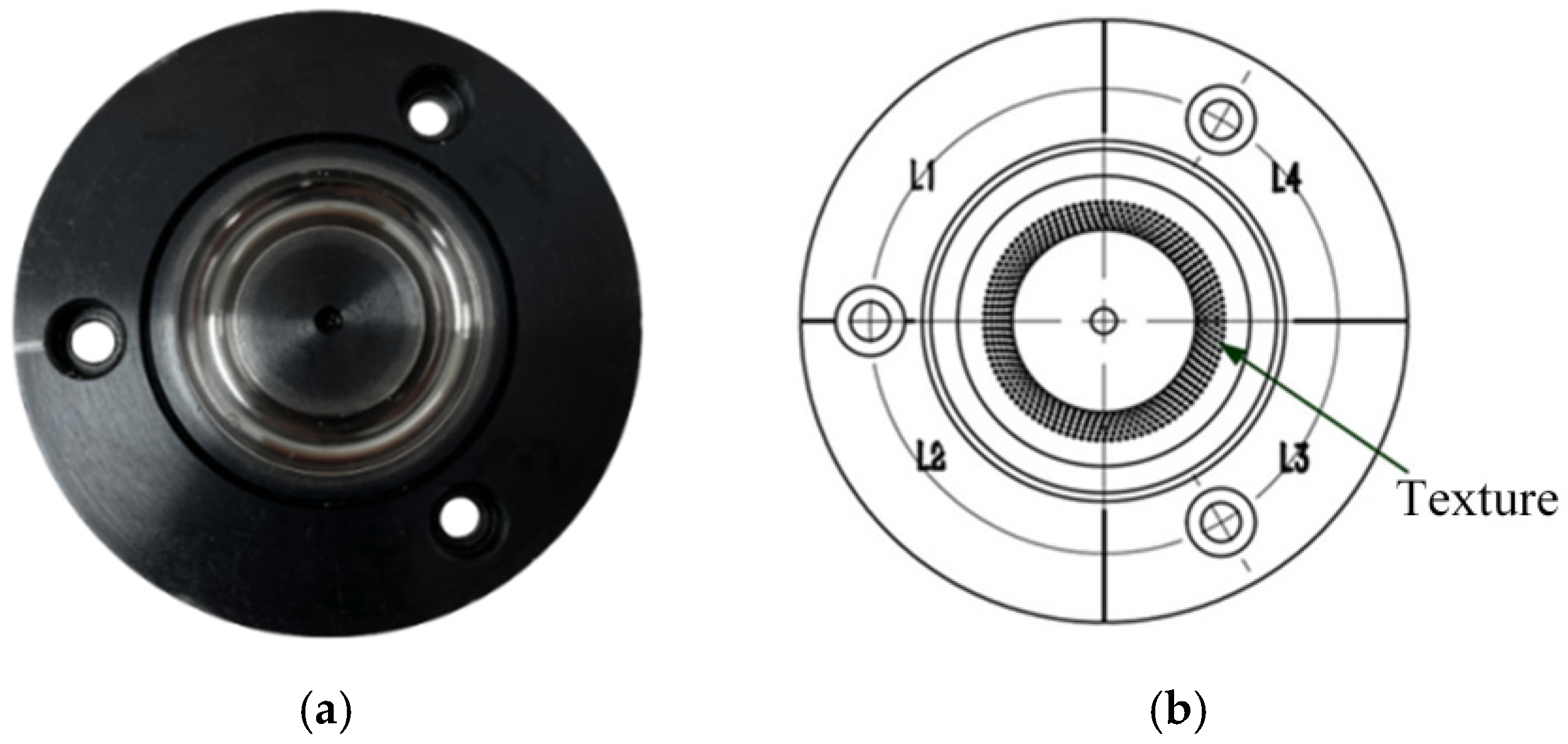
5.1. Design and Manufacture the Textured Workpieces

The spiral raceway of the ball screw has been replaced with the planar circular raceway to simulate the contact state and mechanical properties between the ball and the textured raceway of the ball screws, as shown in Figure 21a. The material of the textured workpiece is consistent with that of the ball screw. The material of the textured workpiece is alloy steel 40Cr, and the hardness of the material is 255HB. The surface roughness of the textured workpiece is the same as that of the ball screw raceway, with Ra = 0.21 μm. The surface textures with four geometric features (as shown in Table 2) are designed and manufactured in four regions (L1, L2, L3, and L4) on the raceway surface of the textured workpiece, as shown in Figure 21b. The design and manufacture of surface textures with different geometric features on the circular raceway surface are beneficial for simulating different axial loads and rotation speeds of the ball screws, reducing the difficulty of manufacturing surface textures on the raceway surface and improving the experimental efficiency. The geometric model of the circular raceway is created to match the contact state and mechanical properties between the ball and the textured raceway of the ball screws, as shown in Figure 21c.
The O0X0Y0Z0 is set as an inertial coordinate system, and the Z0 axis coincides with the central axis of the screw. The OXYZ is the rotating coordinate system of the circular raceway. The coordinate directions of the X-axis and the Y-axis are determined by the base angle θ1, and the origin O and the Z-axis correspond to the origin O0 and the Z0 axis of the O0X0Y0Z0 coordinate system, respectively. The cross-section of the circular raceway is located in the YOZ coordinate system. r1 is the nominal radius of the circular raceway. rs is the section radius of the circular raceway; rs is the same as the section radius of the screw raceway, rs = 3.215 mm. φ1 is the included angle between the positive direction of the Y-axis and the raceway surface. β is the contact angle between the ball and the circular raceway. According to the established geometric model of the circular raceway, the circular raceway equation is written in vector form as follows:
r = r 1 + r S cos φ 1 cos θ 1 , r 1 + r S cos φ 1 sin θ 1 , r S sin φ 1
The partial derivatives of φ1 and θ1 in Equation (43) are obtained as follows:
r φ 1 = r s sin φ 1 cos θ 1 , r s sin φ 1 sin θ 1 , r s cos φ 1
r θ 1 = r 1 + r s cos φ 1 sin θ 1 , r 1 + r s cos φ 1 cos θ 1 , 0
The partial derivatives of φ1 and θ1 in Equations (44) and (45) are obtained as follows:
r φ 1 , φ 1 = r s cos φ 1 cos θ 1 , r s cos φ 1 sin θ 1 , r s sin φ 1
r θ 1 , θ 1 = ( r 1 + r s cos φ 1 ) cos θ 1 , ( r 1 + r s cos φ 1 ) sin θ 1 , 0
r φ 1 , θ 1 = r s sin φ 1 sin θ 1 , r s sin φ 1 cos θ 1 , 0
The first basis vector is expressed according to the principle of differential geometry as follows:
E = r φ 1 · r φ 1 = r S 2 , F = r φ 1 · r θ 1 = 0 , G = r θ 1 · r θ 1 = r 1 + r S cos φ 1 2
The second base vector is denoted as follows:
L = r φ 1 φ 1 · n = r S , M = r φ 1 θ 1 · n = 0 , N = r θ 1 θ 1 · n = r 1 + r S cos φ 1 cos φ 1
Substitute Equations (40) and (41) into the principal curvature equation as follows:
E G F 2 k 2 ( L G 2 M F + N E ) k + L N M 2 = 0
The principal curvatures of the tangent direction and the normal direction at the contact point of the circular raceway are obtained as follows:
k 1 = 1 / r S , k 2 = cos φ 1 / ( r + r S cos φ 1 )
The principal curvature of the tangential direction and the normal direction between the contact point of the ball and the raceway of the ball screws are substituted into Equation (43), and the contact angle at the contact point is β = 3π/2-φ1. The nominal radius of the circular raceway is calculated, r1 = 13.76 mm. The principal curvatures of the circular raceway and the screw raceway are set to be the same to ensure that the contact state and mechanical properties of the elliptical contact area of the circular raceway and the screw raceway are consistent under different operating conditions.
Laser processing technology has the advantages of high machining precision, controllable machining processes, high surface hardness, and no environmental pollution. It has also been widely used in the machining of surface texture. Laser processing technology is used to machine the texture with different geometric features on the circular raceway surface. The textured workpieces with texture diameters of 20 μm, 40 μm, and 60 μm are selected for measurement. The three-dimensional geometric morphology and two-dimensional profile are shown in Figure 22. The textured raceway workpieces are manufactured according to the geometric feature parameters of the texture in Table 2, and the four machining areas of the workpiece correspond to the different geometric feature parameters of the texture.

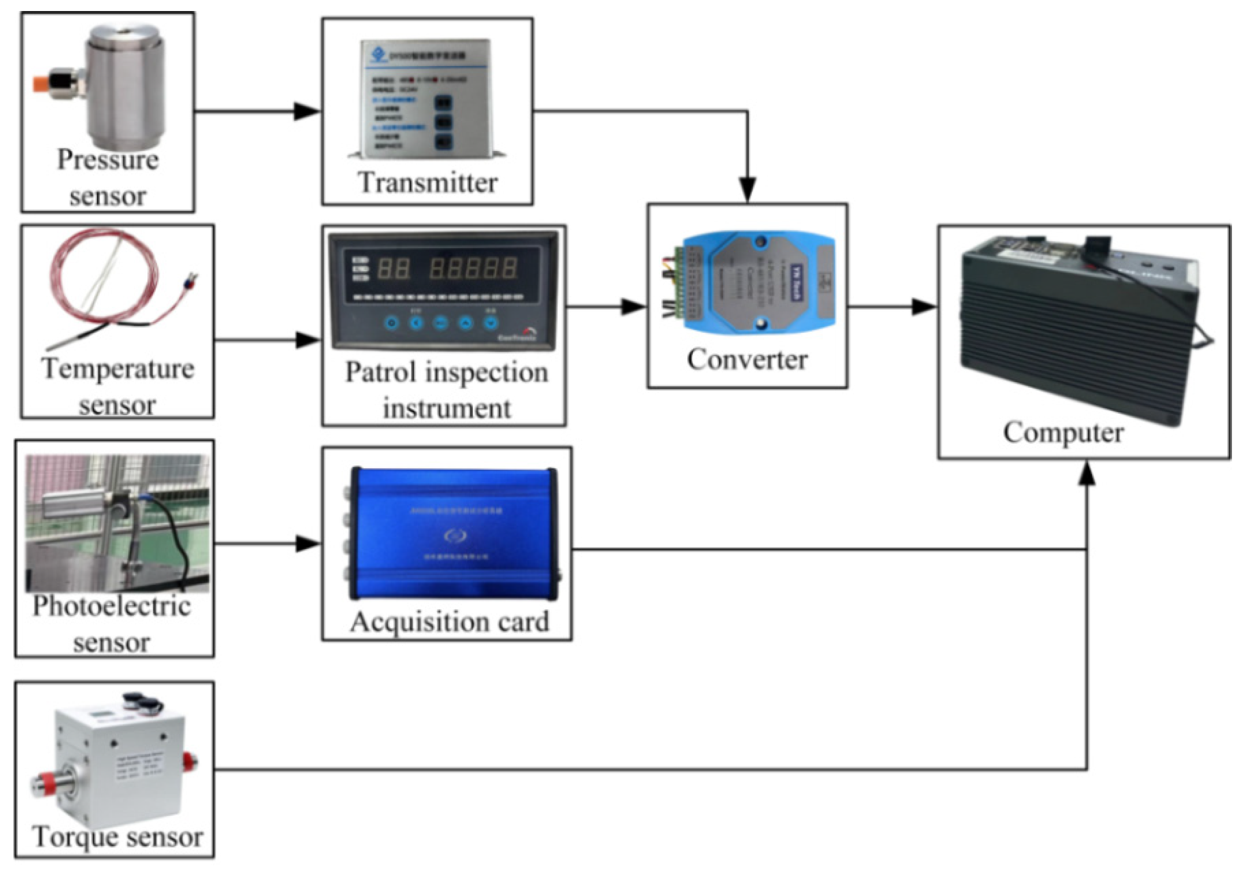
5.2. Experimental Principle and Scheme

The textured workpiece of the ball/raceway friction and wear test bench rotates stably to detect and collect the friction torque between the ball and the textured workpiece. The ball screw is mainly subjected to axial load, and the loading method of the axial load of the ball/raceway friction and wear test bench is shown in Figure 23. The force application mechanism applies a stable and adjustable axial load to the stationary disc, maintaining the consistency of the contact state and mechanical properties of the ball in the textured workpiece and ball screw.
The dynamic system is the core of the ball/raceway friction and wear test bench, as shown in Figure 24. The power of the servo motor is transmitted to the working disc through the reducer, coupling, and torque sensor. The textured workpiece is fixedly installed on the working disc for stable rotation. The signal acquisition system of the ball/raceway friction and wear test bench is shown in Figure 25. The torque sensor is installed between the reducer and the textured workpiece to measure the friction torque between a single working ball and the circular raceway of the textured workpiece. The measured friction torque signal is collected by the acquisition card and stored in the computer.
The servo motor drives the ball/raceway friction and wear test bench, and the speed of the servo motor is controlled by the motor driver. The force sensor measures the axial force of the ball in the textured workpiece in real time. The photoelectric sensor records the phase of the rotation of the textured workpiece in real time to ensure the accuracy of the signals in different regions of the textured raceway. The anti-friction performance experiment of the textured raceway is designed to study the friction reduction performance of the textured raceway of the ball screws under complex operating conditions. The textured workpiece was installed in the ball/raceway friction and wear test bench, as shown in Figure 20. The surface texture with different geometric features was machined on the circular raceway surface of the textured workpieces using laser machining technology, as shown in Figure 22. An oil pump is installed on the experimental device to ensure that the contact surface remains in a lubricated state throughout the experiment.
The circular raceway of the textured workpiece is divided into four regions, and the surface texture corresponding to the geometric features of Table 2 is manufactured in each region. To measure the friction torque between the ball and the textured raceway with different geometric features under different rotation speeds and axial loads of the ball screws in real time, a torque sensor with high sampling frequency and high measurement accuracy is used to collect the friction torque during the operation. The friction torque is measured for 60 s under the steady-state conditions of the ball/raceway friction and wear test bench to reduce the measurement error of the friction torque between the ball and the textured raceway and to accurately investigate the friction reduction characteristics of the textured raceway under various working conditions.

5.3. Analysis of Experimental Results

The torque sensor measures the frictional torque of the ball, and the textured raceway under the condition of entrainment speed us = 167.5 mm/s and normal contact force QA = 37.1 N, and the collected frictional torque is parameterized as follows:
M E = M 1 + M 2 + M 3
M 1 = μ T Q A L A , M 2 = N D μ D Q D L D , M 3 = a 1 sin a 2 x + b 1 cos ( b 2 x ) + c
where ME represents the friction torque measured in the experiment. M1 and M2 are the friction torques of the ball and bearing, respectively. M3 denotes the friction torque due to the coaxial error of the textured workpiece. μT and μD are the friction coefficients at the contact points of the circular raceway and bearing raceway, respectively. QA and QD are the normal contact forces of the balls in the circular raceway and the bearing raceway, respectively. LA is the distance from the contact point between the ball and the circular raceway to the rotation axis of the textured workpiece. LD is the distance between the contact point of the ball and the bearing raceway and the rotation axis of the textured workpiece. ND is the number of balls in the bearing raceway. a1, a2, b1, b2, and c are the coaxial error parameters of the textured workpiece.
The photoelectric sensor collects the optical pulse signal to obtain the friction torque signal of the circular raceway of the textured workpiece in a rotation cycle. The collected friction torque is further analyzed, and the coaxial error of the circular raceway of the textured workpiece under the condition of us = 167.5 mm/s QA = 37.1 N is obtained, as shown in Figure 26a. The collected friction torque signals remove the friction torque caused by the coaxial error of the textured workpiece and the friction torque generated by the bearing rotation to obtain the friction torque between the single working ball and the circular raceway, as shown in Figure 26b. The simulated friction torque of the EHL of the textured raceway of the ball screw is compared with the friction torque measured on the ball/raceway friction and wear test bench under the condition of us = 167.5 mm/s QA = 37.1 N, and the results are shown in Figure 27.
It can be seen from Figure 27 that the friction torque of the textured workpieces with different structural parameters is smaller than that of the untextured workpiece. The circular raceways of the textured workpieces provide anti-friction effects, and the variation trend between the measured friction torque and the geometric features of the texture is in good agreement with the theoretical simulation. The friction torque measured in the experiment is slightly higher than that simulated. The maximum and minimum relative errors of friction torque between the experiment and simulation are 6.2% and 1.3%, respectively, possibly due to raceway machining and workpiece assembly errors. In addition, the actual working conditions of the textured workpiece are more sophisticated than the simulation, and there is a deviation between the geometric feature parameters of the texture with the best friction reduction effect and the simulation results because the machining quality of the textured workpiece is unstable. The friction torque of the experiment is in agreement with the overall trend of the simulation, the correctness of the EHL model, and the effectiveness of the friction reduction of the textured raceway of the ball screws are confirmed.

6. Conclusions

The anti-friction performance of the textured raceway is theoretically analyzed and experimentally studied, considering the impact of the grinding surface of the ball screws on the EHL interaction between the ball and the textured raceway. The main conclusions of the paper are as follows:
  • Theoretical simulation and experimental measurement of the ground surface topography of the screw raceways are conducted based on the formation mechanism of the grinding surface and the geometric model of the screw raceway. The actual measurement and theoretical simulation of the surface roughness of the screw raceway are 0.2128 μm and 0.2072 μm, respectively, and the relative error is only 2.63% to verify the correctness of the forming mechanism of the grinding surface topography of the screw raceway.
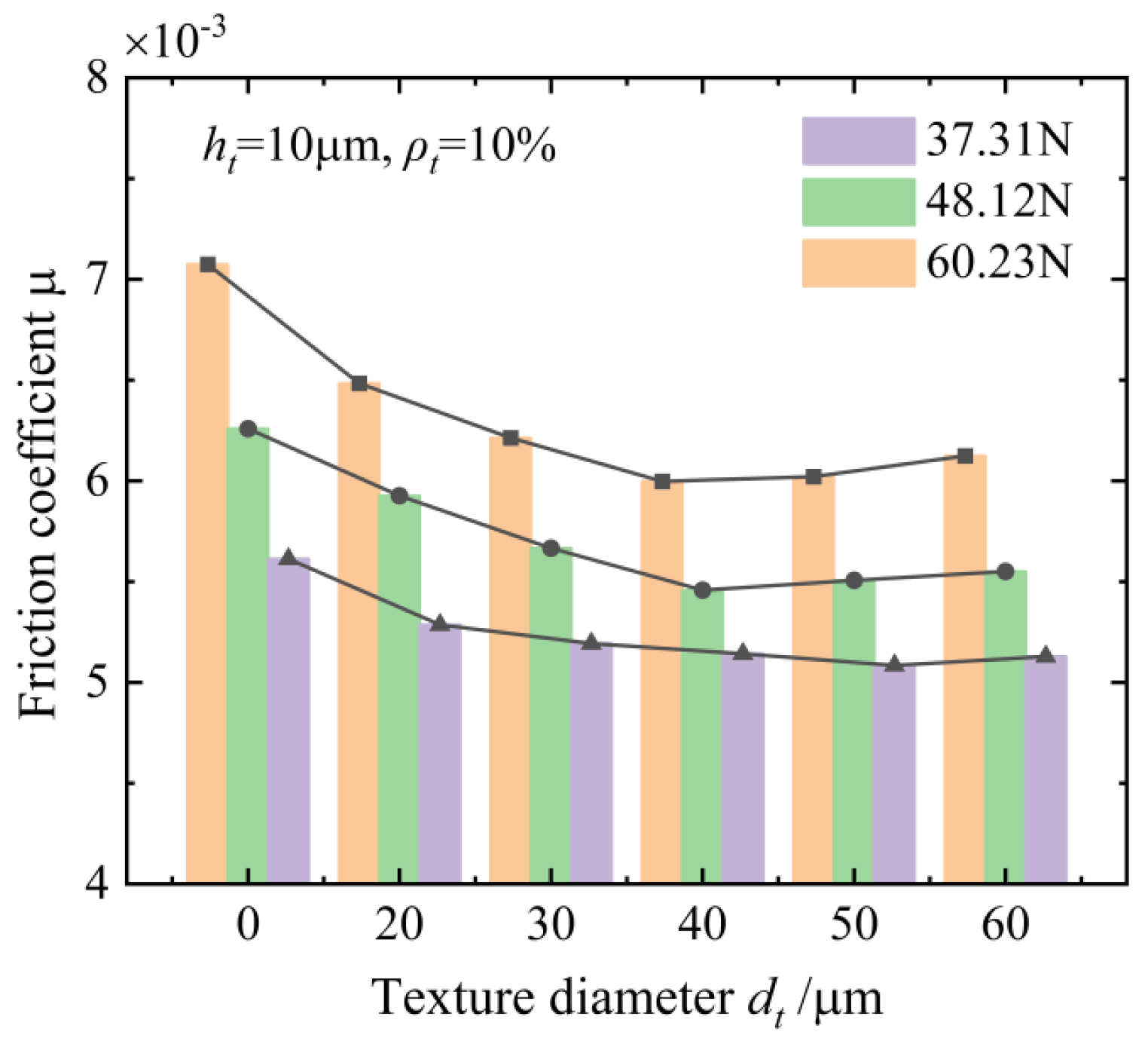
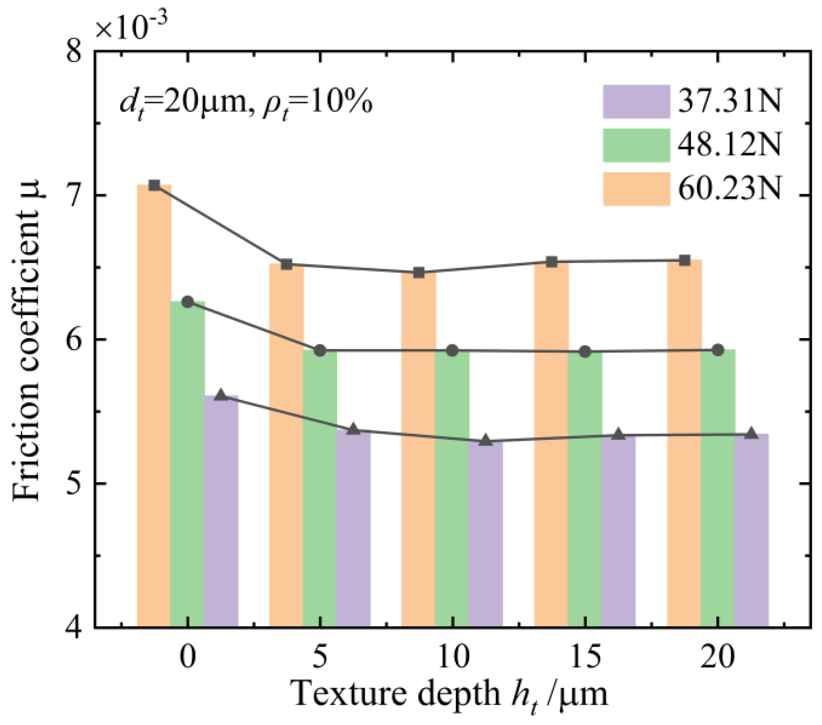
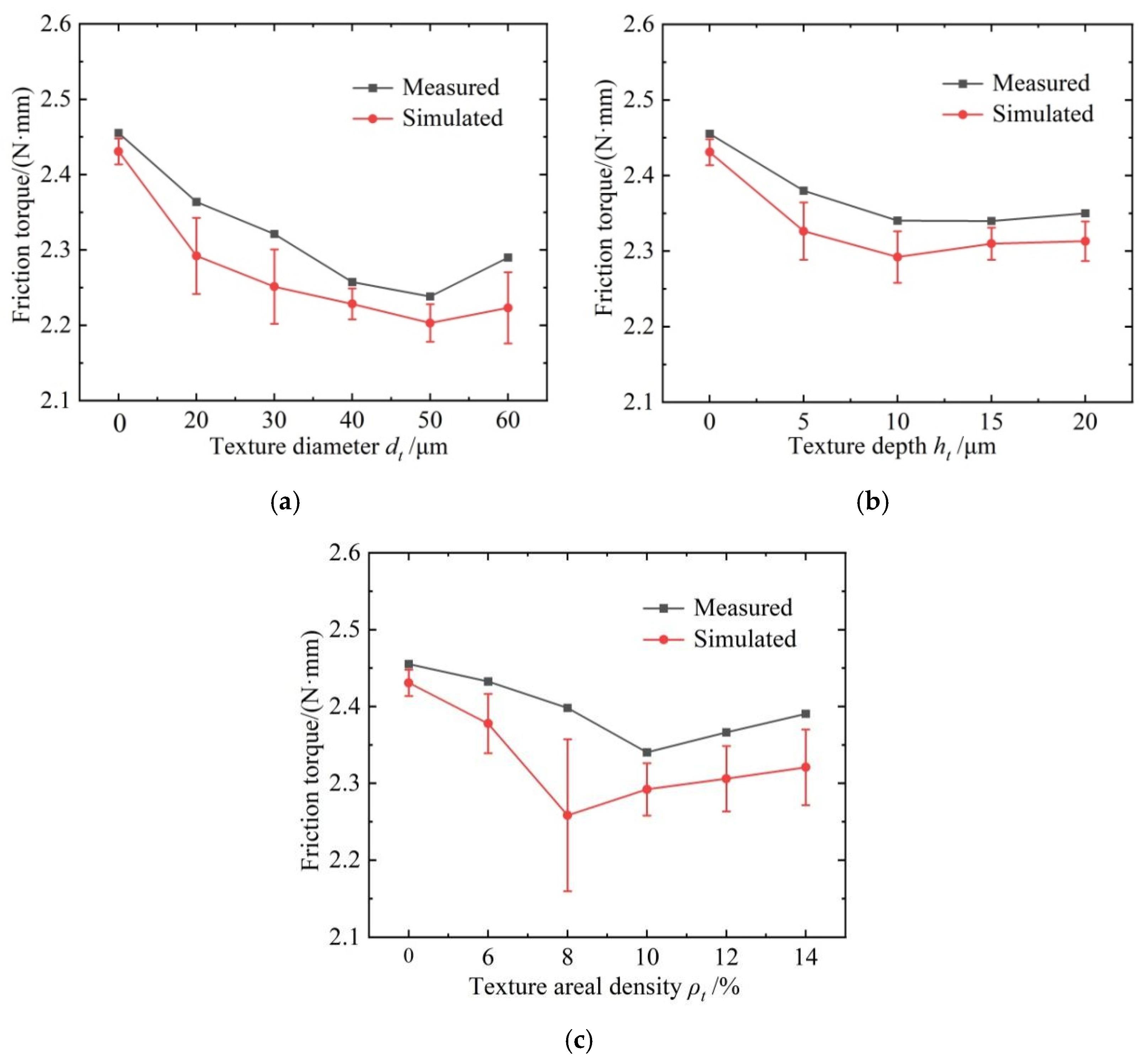
  • The influence of geometric features of the textures on the anti-friction effect under different rotation speeds and axial loads of the ball screws is investigated and discussed. The textured raceway of the ball screws provides a micro-hydrodynamic pressure perturbation effect that reduces the friction coefficient of the contact system of the ball screws by 15.2% at a normal contact force of 60.23 N, an entrainment speed of 167.5 m/s, a texture diameter of 40 μm, a texture depth of 10 μm, and a texture areal density of 10%.
  • The results of the experiments show that the variation trend of the friction-reducing property with the change in the geometric features of the manufactured textures is well in accordance with the theoretical simulation, and the maximum and minimum relative errors are 6.2% and 1.3%, respectively. The correctness of the EHL model of the textured raceway of the ball screws and the effectiveness of the friction reduction effect of the surface texture technology of the ball screws are verified.

Author Contributions

Software, X.G.; Validation, P.G. and X.C.; Data curation, X.Y.; Writing—original draft, Y.Z.; Project administration, M.W. All authors have read and agreed to the published version of the manuscript.

Funding

This study was financially supported by the National Natural Science Foundation of China (Grant Nos. 51975020, 51575014), Beijing Municipal Natural Science Foundation (Grant No. 3202005), Guizhou Provincial Science and Technology Projects (ZK2024-ZD062).

Institutional Review Board Statement

Not applicable.

Informed Consent Statement

Not applicable.

Data Availability Statement

The raw data supporting the conclusions of this article will be made available by the authors on request.

Acknowledgments

I am deeply indebted to Beijing University of Technology for providing an outstanding academic environment.

Conflicts of Interest

The authors declare no conflicts of interest.

Notation

athe grinding depth of the wheel
a1, a2the coaxial error parameters of the textured workpiece
αthe spiral angle of the ball screws
b1, b2the coaxial error parameters of the textured workpiece
ccoaxial error parameters of the textured workpiece
dave the average diameter of the abrasive particles
dethe equivalent diameter of the grinding wheel
ds, dw.the diameters of the grinding wheel and the screw
fothe shear friction coefficient of the oil film
Fprethe preload force
Fsthe friction force between the ball and the raceway
FSA, FSBthe friction force between the ball and the screw raceway and the nut raceway
gm,nthe surface of the workpiece is uniformly discretized into grids, and all grid points form a matrix
g(m, n)the height of the point (m,n) on the surface of the workpiece relative to the global coordinate system
hthe oil film thickness distribution in the contact area
hi,jthe height of the cutting edge of the abrasive grains on the wheel surface
hmaxthe maximum height of the cutting edge of the abrasive grain
hminthe minimum oil film thickness
htthe maximum depth of the texture
h0the oil film thickness in the center of the elliptical contact area.
hi,jall grid points on the surface of the grinding wheel are characterized by a matrix
h(i, j)the height of the cutting edge of the abrasive grain at the point (i, j)
ho, hpthe oil film thickness distribution in the non-textured area and textured area on the raceway surface of the ball screws
i, jthe position of the abrasive grain in the circumferential and radial directions on the surface of the grinding wheel
Lthe lead of the ball screw
LA, LBthe friction arms of the screw and the nut raceway
LDthe distance between the contact point of the ball and the bearing raceway and the rotation axis of the textured workpiece
Li,jthe arc length of the rotational movement of the abrasive cutting edge
Mthe grit number
M1, M2the friction torques of the ball and bearing
M3the friction torque due to the coaxial error of the textured workpiece
MSthe friction torque of the ball screws
MEthe friction torque measured in the experiment
nbthe number of working balls in a nut
nthe rotation speed of the grinding wheel
NDthe number of balls in the bearing raceway
pthe bearing capacity of the oil film
pa, pfthe bearing stress distribution of the asperity and the oil film in the elliptical contact area
pcthe cavitation pressure of the oil film
P A S H the parameter expression of the cross-sectional arc of the screw raceway at contact point A
P A S S the parameter equation of the screw raceway in the coordinate system OXYZ
Qthe total normal contact force of the ball
Qathe normal force of the asperity contact
QAQDthe normal contact forces of the balls in the circular raceway and the bearing raceway
rbthe radius of the ball
rtthe radius of the texture
rsthe radius of gyration of the cutting edge of the abrasive grain
ri,jthe radial distance from the abrasive grain Gi,j to the center of the grinding wheel
Rx, Rythe equivalent curvature radius in the x and y directions of the contact area
R(x, y)the rough surface of the grinding raceway
Rqthe root mean square of the roughness of the screw raceway
tthe time taken for the grain G1 to rotate an angle θ
T S H the coordinate transformation matrix from the coordinate system OXYZ to the Frenet–Serret coordinate system OHtnb of the helical trajectory of the ball center
T H A the coordinate transformation matrix from the Frenet–Serret coordinate system OHtnb to the contact coordinate system AXAYAZA
u1, u2the linear velocities of the ball and raceway along the tangent direction of the spiral trajectory of the ball center
usthe entrainment speed of the oil film
vs, vwthe speeds of the grinding wheel and the screw
vw, vsthe feed speed of the workpiece and the circumferential speed of the grinding wheel
vs,e, vw,ethe equivalent speeds of the grinding wheel and the screw
Vgthe density of the wheel
V(x, y)the elastic contact deformation in the elliptical contact area between the ball and the screw raceway
xin, yinthe coordinates at the entrance of the contact area between the ball and the raceway
xout, youtthe coordinates at the exit of the contact area between the ball and the raceway
Sthe wheel structure number
μthe friction coefficient and friction force between the ball and the raceway
μ1the mean value of the normal distribution
μathe static friction coefficient of the raceway surface
μT, μDthe friction coefficients at the contact points of circular raceway and bearing raceway
θthe rotation angle of the abrasive grain
σthe variance of the normal distribution
βAthe contact angle between the ball and the screw raceway
βASthe central angle corresponding to the cross-sectional arc of the screw raceway
βA0the range of the central angle of the screw raceway
Δx, Δythe grid spacing
Δxs, Δysthe distances between the abrasive grains in the circumferential and axial directions of the grinding wheel
ΔOi,jthe offset distance of the local coordinate system in the x-direction is equal to the movement distance of the workpiece
ΔZi,jthe translation distance of the local coordinate system relative to the global coordinate system in the z-direction
ρ, ηthe density and viscosity of the lubricating oil
ρ0, η0the environmental density and environmental viscosity of lubricating oil
ρtthe areal density of the texture on the screw raceway surface
Ωthe elliptical contact area between the ball and the screw raceway
Ωo, Ωhthe oil film-bearing area of the non-textured and textured in the elliptical contact area
γ ˙ the shear strain rate of the lubricating oil film
τ, τ0the shear stress and the characteristic shear stress of the lubricating oil film
Λthe film thickness ratio
τi,jthe shear force distribution of the oil film

Appendix A. The Expression of the Transformation Matrixes

P A S H = 0 r S cos β A S ( r S r b ) cos β A r S sin β A S ( r S r b ) sin β A 1 , β A β A 0 β A S β A + β A 0
where rs and rb are the cross-sectional arc radius of the screw raceway and the ball radius, respectively. βA is the contact angle between the ball and the screw raceway. βAS is the central angle corresponding to the cross-sectional arc of the screw raceway in the screw raceway area. βA0 is the range of the central angle of the screw raceway. The parameter equation of the screw raceway in the coordinate system OXYZ is expressed as follows:
P A S S = T S H P A S H = r cos θ cos θ [ r S cos β A S ( r S r b ) cos β A ] + sin α sin θ [ r S sin β A S ( r S r b ) sin β A ] r sin θ sin θ [ r S cos β A S ( r S r b ) cos β A ] sin α cos θ [ r S sin β A S ( r S r b ) sin β A ] cos α [ r S sin β A S ( r S r b ) sin β A ] + r θ tan α 1
where T S H denotes the coordinate transformation matrix from the coordinate system OXYZ to the Frenet–Serret coordinate system OHtnb of the helical trajectory of the ball center as follows:
T s H = cos α sin θ cos θ sin α sin θ r cos θ cos α cos θ sin θ sin α cos θ r sin θ sin α 0 cos α r θ tan α 0 0 0 1
The coordinate transformation matrix from the Frenet–Serret coordinate system OHtnb to the contact coordinate system AXAYAZA is expressed as follows:
T H A = 1 0 0 0 0 sin β A cos β A r b cos β A 0 cos β A sin β A r b sin β A 0 0 0 1

References

  1. Zhang, Y.; Zhou, C.; Feng, H. A meticulous friction torque model for a lubricated ball screw considering the surface roughness. Tribol. Int. 2023, 190, 109014. [Google Scholar] [CrossRef]
  2. Li, C.; Xu, M.; Song, W.; Zhang, H. A review of static and dynamic analysis of ball screw feed drives, recirculating linear guideway, and ball screw. Int. J. Mach. Tools Manuf. 2023, 188, 104021. [Google Scholar] [CrossRef]
  3. Li, T.-J.; Zhang, Y.-M.; Su, Y.; Zhang, K.; Wang, Y.-B.; Gao, S.-Z. Dynamic reliability of thermally deduced positioning precision of ball screw systems based on random moving difference method. J. Manuf. Syst. 2021, 61, 171–182. [Google Scholar] [CrossRef]
  4. Xie, Z.; Li, J.; Tian, Y.; Du, P.; Zhao, B.; Xu, F. Theoretical and experimental study on influences of surface texture on lubrication performance of a novel bearing. Tribol. Int. 2024, 193, 109351. [Google Scholar] [CrossRef]
  5. Zhao, J.; Lin, M.; Song, X.; Wei, N. A modeling method for predicting the precision loss of the preload double-nut ball screw induced by raceway wear based on fractal theory. Wear 2021, 486–487, 204065. [Google Scholar] [CrossRef]
  6. Sayfidinov, K.; Cezan, S.D.; Baytekin, B.; Baytekin, H.T. Minimizing friction, wear, and energy losses by eliminating contact charging. Sci. Adv. 2018, 4, eaau3808. [Google Scholar] [CrossRef]
  7. Holmberg, K.; Laukkanen, A.; Hakala, T.; Ronkainen, H.; Suhonen, T.; Wolski, M.; Podsiadlo, P.; Woloszynski, T.; Stachowiak, G.; Gachot, C.; et al. Topography orientation effects on friction and wear in sliding DLC and steel contacts, part 3: Experiments under dry and lubricated conditions. Wear 2021, 486–487, 204093. [Google Scholar] [CrossRef]
  8. Holmberg, K.; Erdemir, A. The impact of tribology on energy use and CO2 emission globally and in combustion engine and electric cars. Tribol. Int. 2019, 135, 389–396. [Google Scholar] [CrossRef]
  9. Kharanzhevskiy, E.V.; Ipatov, A.G.; Makarov, A.V.; Gil’mutdinov, F.Z. Towards eliminating friction and wear in plain bearings operating without lubrication. Sci. Rep. 2023, 13, 17362. [Google Scholar] [CrossRef]
  10. Woydt, M. The importance of tribology for reducing CO2 emissions and for sustainability. Wear 2021, 474–475, 203768. [Google Scholar] [CrossRef]
  11. Rosenkranz, A.; Costa, H.L.; Baykara, M.Z.; Martini, A. Synergetic effects of surface texturing and solid lubricants to tailor friction and wear—A review. Tribol. Int. 2021, 155, 106792. [Google Scholar] [CrossRef]
  12. Shah, R.; Gashi, B.; Hoque, S.; Marian, M.; Rosenkranz, A. Enhancing mechanical and biomedical properties of protheses—Surface and material design. Surfaces Interfaces 2021, 27, 101498. [Google Scholar] [CrossRef]
  13. Boidi, G.; Grützmacher, P.G.; Kadiric, A.; Profito, F.J.; Machado, I.F.; Gachot, C.; Dini, D. Fast laser surface texturing of spherical samples to improve the frictional performance of elasto-hydrodynamic lubricated contacts. Friction 2021, 9, 1227–1241. [Google Scholar] [CrossRef]
  14. Han, D.; Wang, L.; Zhang, S.; Zhang, Q.; Wang, C.; Li, W. The impact of synergistic action of methacrylic acid/zinc oxide/carbon nanotubes on metal Friction and wear. Wear 2024, 546–547, 205342. [Google Scholar] [CrossRef]
  15. Wang, B.; Lai, W.; Li, S.; Huang, S.; Zhao, X.; You, D.; Tong, X.; Li, W.; Wang, X. Self-lubricating coating design strategy for titanium alloy by additive manufacturing. Appl. Surf. Sci. 2022, 602, 154333. [Google Scholar] [CrossRef]
  16. Zheng, Y.; Wang, S. Effect of moderately high temperature heat treatment on surface morphology and structure of quartz fibers. Appl. Surf. Sci. 2012, 258, 4698–4701. [Google Scholar] [CrossRef]
  17. Cai, S.; Chen, G.; Zhou, C. Research and application of surface heat treatment for multipulse laser ablation of materials. Appl. Surf. Sci. 2015, 355, 461–472. [Google Scholar] [CrossRef]
  18. Oláh, A.; Croitoru, C.; Tierean, M.H. Surface properties tuning of welding electrode-deposited hardfacings by laser heat treatment. Appl. Surf. Sci. 2018, 438, 41–50. [Google Scholar] [CrossRef]
  19. Amanov, A.; Karimbaev, R. Improvement in frictional and fatigue performances of AISI 4150H steel by dual ultrasonic nanocrystal surface modification for ball screw applications. Tribol. Int. 2021, 161, 107092. [Google Scholar] [CrossRef]
  20. Tang, W.; Zhou, Y.; Zhu, H.; Yang, H. The effect of surface texturing on reducing the friction and wear of steel under lubricated sliding contact. Appl. Surf. Sci. 2013, 273, 199–204. [Google Scholar] [CrossRef]
  21. Niu, Y.; Hao, X.; Xia, A.; Wang, L.; Liu, Q.; Li, L.; He, N. Effects of textured surfaces on the properties of hydrodynamic bearing. Int. J. Adv. Manuf. Technol. 2022, 118, 1589–1596. [Google Scholar] [CrossRef]
  22. Scaraggi, M.; Mezzapesa, F.P.; Carbone, G.; Ancona, A.; Tricarico, L. Friction properties of lubricated laser-microtextured-surfaces: An experimental study from boundary-to hydrodynamic-lubrication. Tribol. Lett. 2013, 49, 117–125. [Google Scholar] [CrossRef]
  23. Shinde, A.; Pawar, P.; Gaikwad, S.; Kapurkar, R.; Parkhe, A. Numerical Analysis of Deterministic Micro-Textures on the Performance of Hydrodynamic Journal Bearing. Mater. Today Proc. 2018, 5, 5999–6008. [Google Scholar] [CrossRef]
  24. Ye, Q.; Chang, Q.; Shen, Z. The Influence of Surface Texture Depth on the Load Bearing Capacity of Oil Film. Lubr. Eng. 2012, 5, 39–42. [Google Scholar]
  25. Convert, L.; Bourillot, E.; François, M.; Pocholle, N.; Baras, F.; Politano, O.; Costil, S. Laser textured titanium surface characterization. Appl. Surf. Sci. 2022, 586, 152807. [Google Scholar] [CrossRef]
  26. Zhang, D.; Zhao, F.; Li, Y.; Li, P.; Zeng, Q.; Dong, G. Study on tribological properties of multi-layer surface texture on Babbitt alloys surface. Appl. Surf. Sci. 2016, 390, 540–549. [Google Scholar] [CrossRef]
  27. Brizmer, V.; Kligerman, Y.; Etsion, I. A laser surface textured parallel thrust bearing. Tribol. Trans. 2003, 46, 397–403. [Google Scholar] [CrossRef]
  28. Wang, X.; Adachi, K.; Otsuka, K.; Kato, K. Optimization of the surface texture for silicon carbide sliding in water. Appl. Surf. Sci. 2006, 253, 1282–1286. [Google Scholar] [CrossRef]
  29. Fu, Y.; Ji, J.; Bi, Q. The Influence of Partially Textured Slider with Oriented Parabolic Grooves on the Behavior of Hydrodynamic Lubrication. Tribol. Trans. 2012, 55, 210–217. [Google Scholar] [CrossRef]
  30. Ryk, G.; Kligerman, Y.; Etsion, I. Experimental Investigation of Laser Surface Texturing for Reciprocating Automotive Components. Tribol. Trans. 2002, 45, 444–449. [Google Scholar] [CrossRef]
  31. Wang, X.; Liu, W.; Zhou, F.; Zhu, D. Preliminary investigation of the effect of dimple size on friction in line contacts. Tribol. Int. 2009, 42, 1118–1123. [Google Scholar] [CrossRef]
  32. Costa, H.; Hutchings, I. Hydrodynamic lubrication of textured steel surfaces under reciprocating sliding conditions. Tribol. Int. 2007, 40, 1227–1238. [Google Scholar] [CrossRef]
  33. Morris, N.; Leighton, M.; De la Cruz, M.; Rahmani, R.; Rahnejat, H.; Howell-Smith, S. Combined numerical and experimental investigation of the micro-hydrodynamics of chevron-based textured patterns influencing conjunctional friction of sliding contacts. Proc. Inst. Mech. Eng. Part J J. Eng. Tribol. 2015, 229, 316–335. [Google Scholar] [CrossRef]
  34. Etsion, I. Surface texturing for in-cylinder friction reduction. In Tribology and Dynamics of Engine and Powertrain; Woodhead Publishing: New Delhi, India, 2010; pp. 458–469+470e. [Google Scholar]
  35. Overby, A. CNC Machining Handbook: Building, Programming, and Implementation; McGraw-Hill: New York, NY, USA, 2010. [Google Scholar]
  36. Roeland, C.J. Correlation Aspect of the Viscosity-Temperature-Pressure Relation of Lubrication Oils. Ph.D. Thesis, Delft University of Technology, Delft, The Netherlands, 1966. [Google Scholar]
  37. Dowson, D.; Higginson, G.R. A Numerical Solution to the Elasto-Hydrodynamic Problem. J. Mech. Eng. Sci. 1959, 1, 6–15. [Google Scholar] [CrossRef]
Figure 1. The trajectory of an abrasive grain.
Applsci 15 03343 g001
Figure 2. Mapping of the grain trajectories to the workpiece surface.
Applsci 15 03343 g002
Figure 3. Schematic diagram of the grinding of the screw raceway.
Applsci 15 03343 g003
Figure 4. The coordinate system of the ball screws.
Applsci 15 03343 g004
Figure 5. Contact coordinate system of the ball screws.
Applsci 15 03343 g005
Figure 6. The simulated surface topography of the screw raceway: (a) Interpolation results of the geometric morphology of the screw raceway; (b) Surface topography of the grinding raceway; (c) Local enlargement of the surface topography of the grinding raceway; (d) The simulated surface topography profile with the radius removal.
Applsci 15 03343 g006
Figure 7. The measured surface topography of the screw raceway; (a) The measurement steps of the surface topography of the screw raceway; (b) The measured surface topography of the screw raceway; (c) Comparison of measured and standard surface topography profiles; (d) The measured surface topography profiles with the radius removal.
Applsci 15 03343 g007
Figure 8. Schematic diagram of textured raceway of ball screws.
Applsci 15 03343 g008
Figure 9. Calculation flowchart of EHL characteristics of the textured raceway.
Applsci 15 03343 g009
Figure 10. Stribeck friction characteristic curve.
Applsci 15 03343 g010
Figure 11. Contact area of the asperity and oil film.
Applsci 15 03343 g011
Figure 12. The EHL characteristics of the textured raceway of the ball screws; (a) Bearing stress distribution; (b) Film thickness distribution.
Applsci 15 03343 g012
Figure 13. The EHL characteristics of the textured raceway under different texture positions; (a) 2D curve of the EHL characteristic: inlet; (b) Contour map of the bearing stress: inlet; (c) 2D curve of the EHL characteristic: center; (d) Contour map of the bearing stress: center; (e) 2D curve of the EHL characteristic: outlet; (f) Contour map of the bearing stress: outlet.
Applsci 15 03343 g013
Figure 14. Trend of friction coefficient with texture diameter (workpiece#1).
Applsci 15 03343 g014
Figure 15. Trend of friction coefficient with texture depth (workpiece#2).
Applsci 15 03343 g015
Figure 16. Trend of friction coefficient with areal density of the texture (workpiece#3).
Applsci 15 03343 g016
Figure 17. Trend of friction coefficient with texture diameter (workpiece#1).
Applsci 15 03343 g017
Figure 18. Trend of friction coefficient with texture depth (workpiece#2).
Applsci 15 03343 g018
Figure 19. Trend of friction coefficient with areal density of the texture (workpiece#3).
Applsci 15 03343 g019
Figure 20. The ball/raceway friction and wear test bench.
Applsci 15 03343 g020
Figure 21. Structure and geometric model of the circular raceway of the textured workpiece; (a) Textured workpiece; (b) The surface texture on the circular raceway; (c) Geometric model of the circular raceway.
Applsci 15 03343 g021aApplsci 15 03343 g021b
Figure 22. The three-dimensional geometric topography and two-dimensional profile of textured raceway; (a)Texture topography dt = 60 μm, ht = 10 μm, ρt = 10%; (b) Texture topography dt = 40 μm, ht = 10 μm, ρt = 10%; (c) Texture topography dt = 20 μm, ht = 5 μm, ρt = 10%; (d) Texture topography dt = 60 μm, ht = 10 μm, ρt = 10%; (e) Texture topography dt = 40 μm, ht = 10 μm, ρt = 10%; (f) Texture topography dt = 20 μm, ht = 5 μm, ρt = 10%.
Applsci 15 03343 g022
Figure 23. The force application system of the ball/raceway friction and wear test bench; (a) The loading mode of the axial loads; (b) The force application mechanism.
Applsci 15 03343 g023
Figure 24. Dynamical system of the ball/raceway friction and wear test bench.
Applsci 15 03343 g024
Figure 25. Signal acquisition system of the ball/raceway friction and wear test bench.
Applsci 15 03343 g025
Figure 26. Analysis of friction torque between the ball and textured workpiece; (a) Friction torque including coaxial error; (b) Friction torque of the single working ball.
Applsci 15 03343 g026
Figure 27. Comparison of experimentally measured and simulated friction torques; (a) Change texture diameter; (b) Change texture depth; (c) Change areal density of the texture.
Applsci 15 03343 g027
Table 1. The parameters of the ball screws.
The Parameter NamesThe Parameter Value
Workpiece feed speed vw (m/s)0.1
Ball diameter 2rb (mm)5.953
The nominal radius r (mm)16
Wheel diameter ds (mm)310
Grinding depth a (µm)5
The preload force Fpre (N)1500
Lead of ball screw L (mm)10
The rotation speed of the grinding wheel n (r/min)3000
Table 2. The geometric feature parameters of the textures.
Workpiece#1Areal density ρtDepth ht/μmDiameter dt/μm
10%1030405060
Workpiece #2Areal density ρtDiameter dt/μmDepth ht/μm
10%205101520
Workpiece #3Depth ht/μmDiameter dt/μmAreal density ρt
10206%8%12%14%
Disclaimer/Publisher’s Note: The statements, opinions and data contained in all publications are solely those of the individual author(s) and contributor(s) and not of MDPI and/or the editor(s). MDPI and/or the editor(s) disclaim responsibility for any injury to people or property resulting from any ideas, methods, instructions or products referred to in the content.

