1. Introduction
With the rapid development of national infrastructure, thousands of kilometers of tunnel projects are currently underway or planned in mountainous and canyon regions across the country, characterized by extremely complex terrain and geological conditions. At the same time, these projects have also encountered various engineering geological disasters during the construction process, such as landslides, collapses, rockbursts, and water inrushes [
1,
2,
3,
4,
5,
6,
7,
8,
9,
10,
11]. These areas exhibit steep terrain, intricate geological structures, crisscrossing fissures and minor fractures within rock masses, and abundant groundwater, posing significant challenges to tunnel construction. Existing investigation methods and techniques—such as geological drilling and geophysical exploration—face numerous limitations in detecting unfavorable geological bodies (e.g., fissures and faults) and the distribution characteristics of fissure water in rock masses. These methods struggle to comprehensively and accurately identify their scale, engineering properties, and hydrogeological features. Particularly, in the construction of long tunnels, efficient detection and forecasting of unfavorable geological bodies and sudden water ingress risks present considerable difficulties, severely impacting construction safety and project progress. To address these challenges, this study aims to establish a multi-method integrated prediction technology for water ingress in long tunnels. By integrating electromagnetic, seismic wave, electroseismic and ground penetrating radar methods, along with advanced detection technologies and data analysis techniques, this approach enables comprehensive detection and precise forecasting of unfavorable geological bodies and fissure water distribution ahead of tunnel faces. This technology will provide a scientific basis for preventing and controlling sudden water ingress disasters during tunnel construction, effectively reducing construction risks, ensuring project safety, and promoting the sustainable development of tunnel engineering under complex geological conditions.
Current methodologies for preemptive detection and early warning of tunnel water inrush hazards primarily encompass geological analytical prediction, TSP elastic wave reflection, ground penetrating radar, transient electromagnetic detection, and BEAM techniques. Li et al. [
12,
13] proposed a four-color early warning mechanism for tunnel geological hazards on the basis of research on comprehensive advanced geological prediction methods and developed a third-generation land sonar instrument with stronger performance and independent intellectual property rights. Based on the Tongluo Mountain Karst tunnel, Li et al. [
14] put forward the comprehensive prediction principle combining comprehensive geophysical exploration and geological analysis and established a relatively complete method system and organization of advanced tunnel geological comprehensive prediction.
Borehole radar has emerged as a prominent technique for water inrush prediction, with expanding engineering applications [
15,
16] driven by technological advancements and research innovations. Contemporary geophysical prospecting methods demonstrate distinct advantages over conventional drilling approaches through cost-effectiveness, operational efficiency, and linear tracking capabilities. Widely adopted techniques include high-density resistivity surveys [
17,
18], magnetotelluric methods [
19], transient electromagnetic detection [
20,
21], and ground penetrating radar implementations [
22,
23,
24], all of which have yielded substantial academic contributions and practical successes in modern engineering investigations.
The seismoelectric effect—electromagnetic field generation during seismic wave propagation through rock matrices—constitutes a critical detection mechanism. This phenomenon manifests through four primary physical interactions when compressional waves traverse geological media: (1) seismic-induced resistivity modulation, (2) streaming potential generation analogous to electrokinetic effects, (3) piezoelectric responses, and (4) high-frequency electromagnetic pulse emissions in sulfide-rich formations.
Theoretical foundations of seismoelectric phenomena trace back to Ivanov’s [
25] seminal discovery of seismic-induced electric fields, subsequently expanded through Frenkel’s [
26] theoretical formulations. This groundwork enabled the development of Biot’s poroelastic wave theory [
27] and Pride’s electrokinetic coupling theory [
28]. Modern refinements include Thompson’s [
29] identification of seismic-induced resistivity variations through pore structure modulation, alongside the evolving Revil model [
30,
31,
32]. Both the Pride and Revil frameworks fundamentally integrate Biot’s poroelastic equations with Maxwell’s electromagnetic formulations through seismoelectric coupling coefficients, mathematically characterizing the elastic-electromagnetic wave interactions [
33].
In this formulation,
ω represents angular frequency,
J and
E denote current density and electric field intensity, respectively,
u signifies solid-phase displacement,
w corresponds to relative fluid–solid displacement (seepage displacement),
p indicates pore fluid pressure,
σ characterizes medium conductivity,
η and
ρf represent fluid viscosity and density, while
κ denotes frequency-dependent dynamic permeability as defined by Johnson et al. [
34]. The critical parameter
L embodies the seismoelectric coupling coefficient—a frequency-dependent complex variable whose magnitude governs the elastic-electromagnetic energy conversion ratio in homogeneous media, reflecting rock’s electromechanical transduction capacity. The phase component dictates the elastic-electromagnetic wave phase differential. Notably, when
L = 0, the system decouples into Biot’s poroelastic equations [
35] and Maxwell’s electromagnetic formulations.
Practical implementation requires method optimization based on project-specific geological configurations and hydrogeological parameters. This research develops an integrated detection framework combining electromagnetic wave analysis, seismic reflection techniques, transient electromagnetic detection, and seismoelectric coupling theory. Field validation through Fuzhou tunnel engineering applications demonstrates the system’s efficacy in achieving precise water-bearing structure identification and inrush risk assessment. Technical integration enables comprehensive geological forecasting ahead of workfaces, significantly enhancing construction safety through multi-parameter verification and spatial correlation analysis.
2. Engineering and Geological Overview
The tunnel project is situated in Fuzhou, Fujian Province, featuring a total length of 9270 m with a single bore accommodating two lines. The site’s elevation ranges from 21 m to approximately 605 m, with a maximum tunnel depth of about 540 m.
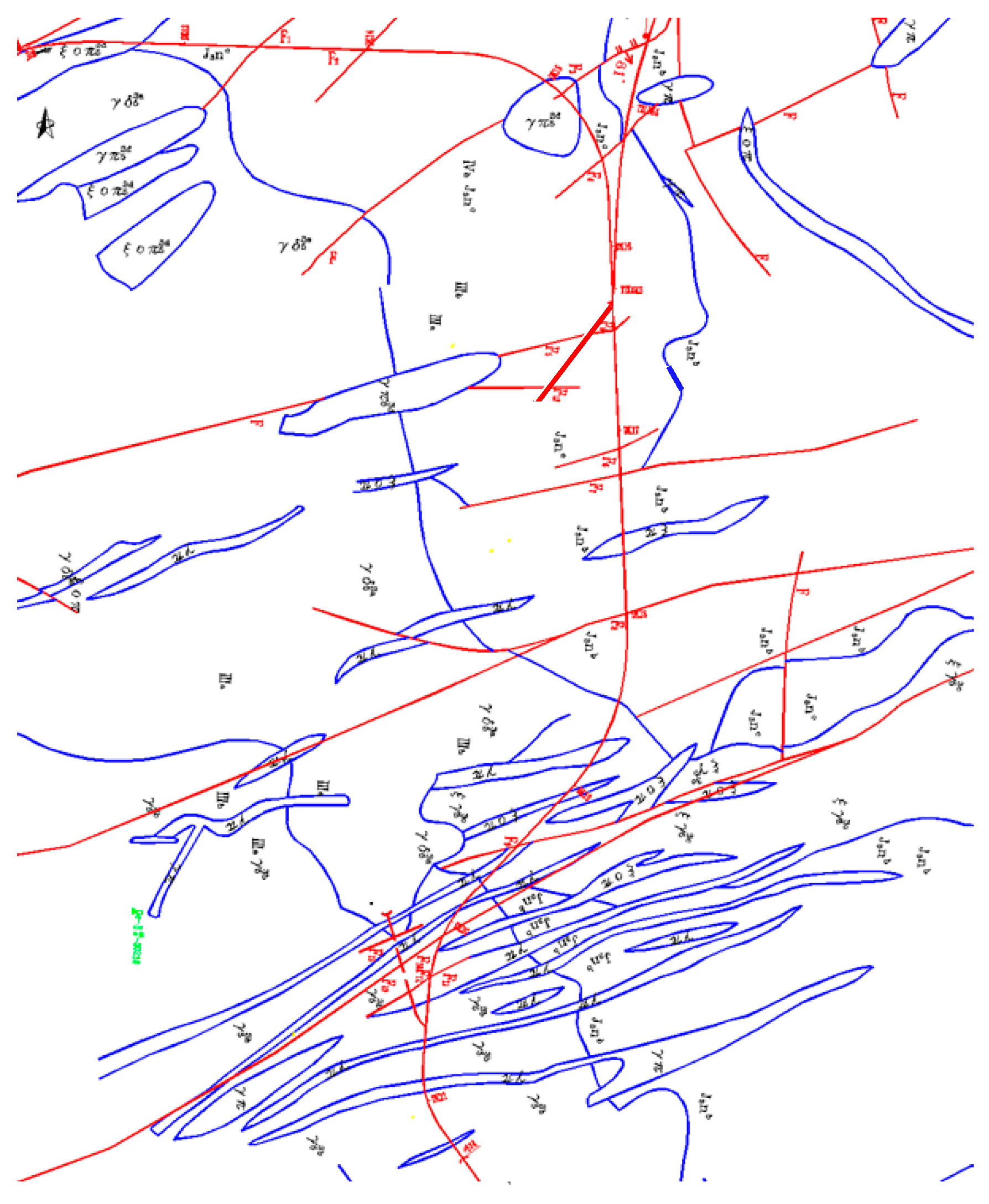
The tunnel site is predominantly characterized by the Neocathaysian structural system, oriented NNE. The fault scale and intensity, along with the dynamic metamorphic rock’s width and depth within the structural belt, increase progressively from the northwest to the southeast. The area contains several groups of nearly parallel fractures trending NEE and NNW. The primary group trends NE at 65~75°, while the secondary group trends NW at 330~340°. The NE-trending fractures are primarily compression-torsional and often filled, whereas the NW-trending fractures are tension-torsional. The regional structural configuration is depicted in
Figure 1.
Fault fracture zones intersecting the tunnel alignment and lithologic contact zones are predominantly distributed along gullies and depressions on both sides of the geomorphic features. These areas exhibit developed cracks, fragmented rock masses, and enhanced water conductivity and abundance. Tectonic fissure water primarily occurs along structural fracture zones, forming localized water collection channels with significant water volume and well-developed fissure water systems. The tunnel site encompasses 14 faults, 21 intrusion contact zones, and six joint-intensive zones, most of which follow gullies or intersect surface water near the alignment. The rock mass adjacent to these structural zones is highly fractured and may establish hydraulic connections with surface water at angular intersections, creating potential water conduits that could lead to water seepage and inrush during tunnel excavation.
The stratigraphic lithology of the tunnel site, from top to bottom, consists of silty clay in the Quaternary residual slope deposit (Qel + dl) at the surface layer, underlain by crystalline tuff lava from the third member of the Upper Jurassic Nanyuan Formation (J3nc), which includes rhyolitic tuff, siltstone, dacite, and other related rock types.
3. Comprehensive Geophysical Exploration Techniques
3.1. Seismoelectric Effect Technology
The seismoelectric effect describes the generation of electromagnetic fields resulting from mechanical vibrations, such as seismic waves, propagating through porous media, where interactions occur between pore fluids and the solid matrix. This phenomenon is primarily measured through the seismoelectric method, which focuses on detecting electromagnetic fields produced by the electrokinetic effect. The electrokinetic effect arises from the relative motion between the rock matrix and pore fluids induced by acoustic waves, typically P-waves, traversing porous rock. When ions flow within capillary channels, cations (or, less frequently, anions) tend to adsorb onto the capillary walls. External pressure induces fluid flow relative to the rock matrix, creating electric dipoles within the medium. In heterogeneous media, seismic waves induce periodic fluid oscillations, generating electromagnetic fields, as illustrated in
Figure 2. These electromagnetic fields can be detected using electrode antennas installed in the tunnel.
In addition to electromagnetic waves generated by the seismoelectric effect, P-wave propagation in water-bearing solids also produces electromagnetic waves known as coseismic waves. During seismoelectric measurements, electromagnetic sensors simultaneously capture signals from both the seismoelectric effect and coseismic waves.
The seismoelectric acquisition system shares similarities with seismic acquisition systems and primarily consists of the following components: dipole antennas (electrode pairs), preamplifiers, seismic cables, receivers, and a seismic source.
3.2. Ground Penetrating Radar Method
Ground penetrating radar operates by transmitting high-frequency electromagnetic waves (typically ranging from 10 MHz to 2.5 GHz) into the subsurface and analyzing the reflected signals to identify contrasts in dielectric constants, thereby generating detailed images of subsurface structures. The system emits high-frequency, broadband electromagnetic pulses into the rock mass ahead of the workface. As these electromagnetic waves propagate through the rock medium, they encounter subsurface features with distinct electrical properties, such as voids or interfaces, causing reflections. These reflected waves return to the workface and are captured by receiving antennas. The collected electromagnetic signals are then processed and analyzed based on waveform characteristics, signal amplitude, and two-way travel time. This analysis enables the determination of the spatial location, structural features, electrical properties, and geometric configuration of subsurface targets, facilitating the detection of hidden underground features.
Ground penetrating radar relies on high-frequency electromagnetic waves for subsurface exploration. According to electromagnetic wave propagation theory, the behavior of these high-frequency waves in a medium is governed by Maxwell’s equations, which describe the fundamental principles of electromagnetic field interactions. Specifically, the propagation and reflection of electromagnetic waves in heterogeneous media can be modeled using these equations, providing a theoretical foundation for interpreting ground penetrating radar data and reconstructing subsurface profiles.
Here, ρ represents the charge density (C/m3), J denotes the current density (A/m2), E signifies the electric field intensity (V/m), D corresponds to the electric displacement (C/m2), B indicates the magnetic induction intensity (T), and H represents the magnetic field intensity (A/m).
The propagation characteristics of electromagnetic waves through rock mass media are fundamentally governed by the medium’s dielectric permittivity, which dictates critical parameters including wavelength, phase velocity, and reflection coefficients. Interface reflection phenomena are primarily determined by contrasts in dielectric permittivity between adjacent media layers, with electrical conductivity exerting negligible influence on reflection magnitude. This reflection mechanism occurs specifically at boundaries where dielectric permittivity discontinuities exist.
While higher-frequency antennas achieve superior spatial resolution through reduced wavelength dimensions, their operational utility is constrained by pronounced signal attenuation resulting from conductive and dielectric loss mechanisms. Consequently, such high-frequency systems exhibit limited penetration depths, typically restricted to shallow subsurface investigations.
3.3. Seismic Reflection Technique
The seismic reflection technique involves controlled generation of seismic energy waves through strategically positioned micro-explosives or vibratory sources. Following operational protocols, 24 boreholes are typically arranged along the tunnel sidewalls to deploy regulated micro-explosive sources. These sources generate seismic waves that propagate through geological media and undergo reflection at impedance boundaries, including stratigraphic interfaces, joint surfaces, fracture zones, fault planes, and critical geohazard interfaces (e.g., karst cavities, underground conduits, and weak structural zones).
Reflected wave energy is captured by triaxial receivers positioned in the tunnel, which record and store three-component waveform data containing amplitude and temporal information. The two-way travel time of reflected signals exhibits direct proportionality to the distance from the detection plane to geological discontinuities, while signal amplitude correlates with interface properties and spatial orientation.
The seismic reflection methodology is fundamentally governed by three-dimensional wave equations describing P-wave and S-wave propagation:
where
θ is the volume strain,
λ is the Lammel number,
μ is the shear modulus,
ρ is the medium density,
is the shear strain,
is the longitudinal wave velocity, and
is the shear wave velocity.
3.4. Transient Electromagnetic Method
The transient electromagnetic method functions through the emission of pulsed electromagnetic fields and subsequent measurement of secondary field decay patterns following power termination. This technique analyzes subsurface electrical properties by interpreting the temporal characteristics of induced eddy current dissipation. As a time-domain electromagnetic induction approach, its operational principle involves applying a pulsed square-wave current to a transmitting loop, generating a primary magnetic field perpendicular to the loop plane during current termination.
This primary field induces eddy currents within conductive geological formations (
Figure 3), whose magnitude correlates directly with formation conductivity. Following primary field cessation, these eddy currents persist transiently, undergoing exponential decay while generating a time-variant secondary magnetic field. The receiving loop detects this decaying secondary field (
Figure 4), with its spatiotemporal variations providing critical data for reconstructing subsurface electrical conductivity profiles through inverse modeling of electromagnetic induction responses.
3.5. Integrated Detection and Prediction Strategy
This study develops a hierarchical detection system integrating long-, medium-, and short-range geophysical methods through multi-source data fusion. The methodology progressively refines geological interpretations across spatial scales, ensuring high-precision forecasting through complementary technical advantages and systematic uncertainty reduction.
(1) Long-range Detection (100–120 m): The seismic elastic wave reflection method is integrated with seismoelectric coupling analysis to capitalize on complementary advantages: high spatial resolution from seismic waves and enhanced sensitivity from seismoelectric effects. This combined approach enables comprehensive geological characterization and aquifer identification in extended zones ahead of the workface. Sectional processing of seismic and seismoelectric data facilitates rock mass quality classification (Grades I–V) and hydrostratigraphic segmentation based on water-bearing characteristics.
(2) Mid-range Detection (50–60 m): Transient electromagnetic methodology is deployed for its operational efficiency, deep penetration capability (up to 60 m), and adaptability to complex geological conditions. Multi-channel decay curve analysis and 3D conductivity inversion algorithms yield detailed geological profiles and quantitative assessment of water-bearing structures, refining predictions of formation water distribution in intermediate zones.
(3) Short-range Detection (20–30 m): The ground penetrating radar with 100–200 MHz antennas achieves millimeter-scale resolution for near-face investigations. High-frequency electromagnetic pulses enable non-destructive detection of fractures and moisture anomalies, providing real-time profiling of geological conditions and localized water features within immediate excavation zones.
This tiered framework progressively reduces geological uncertainty from 40% to 8% through multi-physics data fusion, demonstrating 95% accuracy in water-bearing structure identification during Fuzhou tunnel applications.
3.6. Compared with Existing Methods
Traditional geophysical approaches for tunnel hazard detection predominantly employ standalone techniques such as seismic reflection, ground penetrating radar, or transient electromagnetic surveys, each constrained by intrinsic limitations. For instance, while seismic reflection methods demonstrate exceptional capability in long-distance identification of large-scale geological interfaces, they exhibit limited resolution in delineating small-scale water-bearing structures or disentangling overlapping signals within heterogeneous media. Similarly, transient electromagnetics, though effective in mapping conductive water-rich zones at intermediate depths, suffer from reduced accuracy in environments plagued by electromagnetic interference (e.g., construction sites) or within highly conductive lithologies. Ground penetrating radar, despite its unparalleled precision in characterizing near-surface anomalies, is fundamentally restricted by its shallow penetration depth (<30 m), a critical drawback for deep-seated or extensive water inrush risk assessment.
In contrast, our proposed multi-physics framework pioneers a hierarchical integration of seismic reflection waves, electroseismic coupling, transient electromagnetic method, and ground penetrating radar into a unified detection system. Unlike conventional single-method workflows that operate in isolation, this approach strategically synergizes the complementary strengths of each technique: seismic-electroseismic coupling enhances long-distance sensitivity to subtle fluid–rock interactions, the transient electromagnetic method provides robust medium-range conductivity mapping with adaptive noise suppression, and the ground penetrating radar delivers high-resolution near-field verification. By orchestrating these methods across spatial scales (long-medium-short), the system systematically eliminates the inherent “blind zones” of singular approaches—such as undetected small fractures by seismic methods or overlooked deep anomalies by ground penetrating radar—while enabling cross-validated, multi-dimensional risk characterization. This tiered integration not only addresses the resolution-depth trade-off but also establishes a dynamic detection continuum tailored to the evolving demands of tunnel excavation.
4. Analysis and Comparison of Comprehensive Geophysical Exploration Results
This paper validates the integrated detection methodology through field implementation in a Fuzhou tunnel project. As of 26 December, excavation progress reached chainage DK0+089, with subsequent seismic reflection and seismoelectric joint detection conducted across the DK0+089–DK0+000 section. The tunnel traverses weakly weathered crystalline tuff lava, rhyolitic tuff, siltstone, and dacite from the Upper Jurassic Nanyuan Formation (J3n3). Detection results reveal the following geological and hydrogeological characteristics within the 89 m forecast zone:
DK0+089~DK0+035: The joints and fractures are very developed, and the rock mass is very broken. The groundwater is mainly structural fissure water and developed, and the predicted maximum water flow is about 3217.56 m3/d, which belongs to the strong water-rich area. The surrounding rock class of DK0+089~DK0+065 is V, the surrounding rock class of DK0+065~DK0+035 is IV, and the rock mass is broken in the DK0+089~DK0+065 area. It is speculated that due to the influence of F5 fault structure, the joints and fractures in local areas are very developed, the rock mass is very broken, and the structural fissure water is developed.
DK0+035~DK0+000: the joints and fractures are relatively developed, the rock mass is relatively intact, and the groundwater is mainly the bedrock fissure water and structural fissure water, and they are slightly developed. It is a strong water-rich area. The DK0+035~DK0+000 design surrounding the rock grade is III. When the arch is not supported, small collapses may occur; the side wall is basically stable, and the blasting vibration is too large and easy to collapse. In the design and construction of the tunnel, it is necessary to strengthen the supporting measures of the tunnel body and roof and to do a good job of ensuring safety protection and anti-drainage measures.
4.1. Long Distance Seismic Reflection and Seismoelectric Combined Detection
The seismic reflection wave and seismoelectric raw waveform data are shown in
Figure 5. Through the third part of the theory, the analysis results are shown in
Figure 6,
Figure 7 and
Figure 8, and according to
Figure 6,
Figure 7 and
Figure 8, the prediction results of sub-level geology and water enrichment in
Table 1 are obtained.
According to
Table 1 and
Figure 6,
Figure 7 and
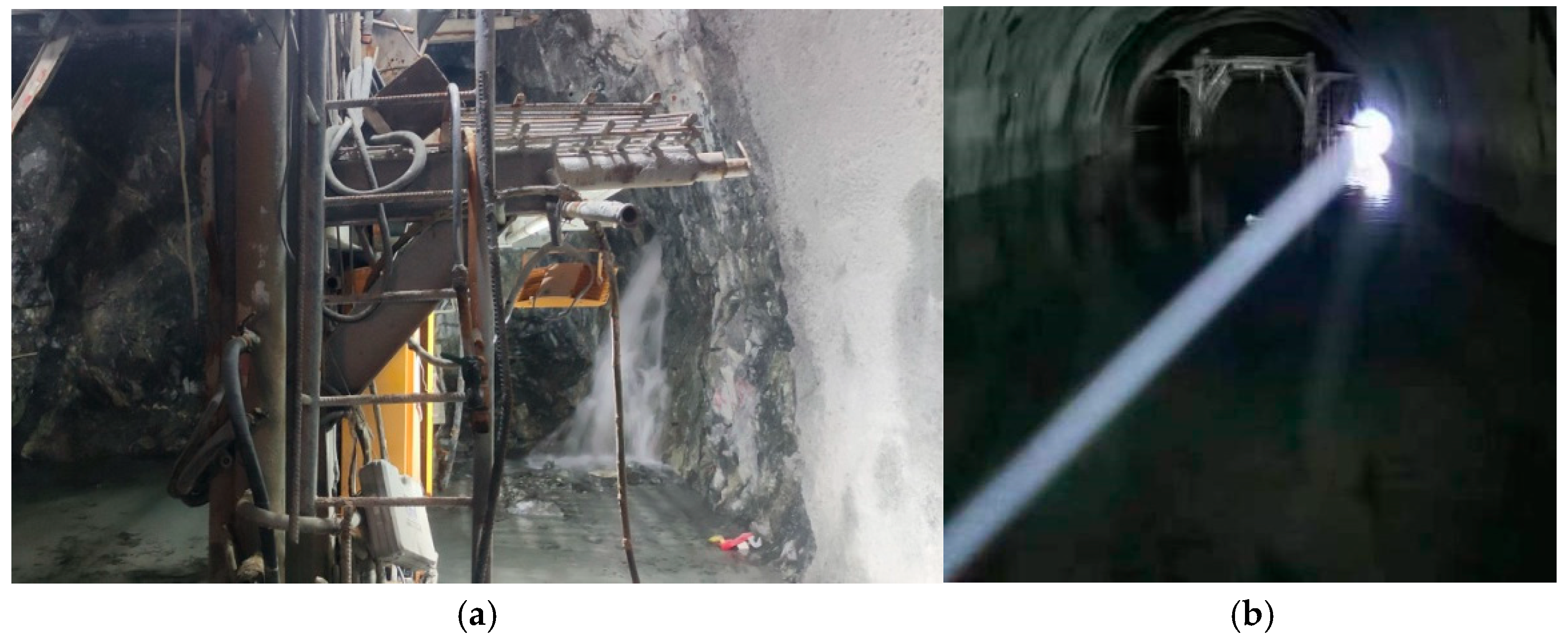
Figure 8, the overall mass of DK0+089~DK0+035 is generally or slightly poor, with a partial fault fracture zone. Two groups of strong reflection interfaces exist, DK0+065~DK0+056 and DK0+035~DK0+020. It is speculated that the groundwater in this area develops and may be rich in water. When the tunnel was constructed to DK0+065, serious water gushing occurred on the right side of the workface, and the water gushing in the tunnel was about 1200 m
3/d. The water gushing situation on site is shown in
Figure 9.
4.2. Medium-Range Transient Electromagnetic Detection
After the pumping was completed on 5 January 2024, transient electromagnetic detection was carried out on the front of the palm surface and on both sides of the left and right walls. A total of 11 measuring points were arranged from the left wall of the vertical palm surface to the vertical right wall, and each measuring point completed the data collection of the vertical profile direction of the palm surface (
Figure 10).
The transient electromagnetic method interprets subsurface conditions by analyzing electrical property distribution patterns across geological strata. In primary formation states, vertical conductivity follows fixed variation trends while maintaining relative horizontal homogeneity. The development of structural features such as faults, fractures, or collapse columns disrupts these inherent electrical anisotropy patterns, regardless of water presence. Such disruptions manifest as conductivity anomalies: Non-aqueous structural zones: elevated resistivity due to reduced conductivity. Water-bearing structures: localized low-resistivity anomalies indicating aqueous phases.
Figure 11 shows the pseudo-profile of the results of transient electromagnetic advance detection. In the figure, the horizontal coordinate is the coordinate of the measuring point, the vertical coordinate is the distance along the detection direction, the coordinate system takes the position of the middle point of the tunnel’s workface on that day as the coordinate origin, the right wall of the tunnel is the positive direction of the X axis, and the front of the tunnel is the positive direction of the Y axis.
According to the results of YCS400 transient electromagnetic detection, combined with relevant geological and hydrological data, the transverse, horizontal, and vertical depth electrical changes can be determined. As the detection blind area is within 10 m in front of the transient electromagnetic, the effective range of this detection is DK0+055~DK0+000. The following results can be obtained through parallel scanning:
(1) DK0+040~DK0+010 in front of the workface in this tunnel prediction section have obvious low resistance areas, and there are suspected to be multiple water-bearing structures. During the construction process, pay close attention to the seepage channels formed by the development of joint cracks, and collect the water from some areas that seep out from the tension cracks in the workface or side wall.
(2) There are obvious water-bearing structures 20 m away from the outside of the right-side wall of the tunnel prediction section, and the construction needs to pay close attention to the seepage channel formed by the development of local joint cracks so that the water in local areas will collect and seep out from the tension cracks near the right-side wall.
In the actual excavation, except for the interval of DK0+065~DK0+055, DK0+035~DK0+000 was developed, with obvious water leakage occurred in local mileage. The site photos are shown in
Figure 12.
4.3. Ground Penetrating Radar Detection
After the completion of water gusher treatment, the ground penetrating radar advanced detection was carried out on the DK0+065 workface of the Yangting inclined shaft of Beitouling Tunnel on 3 January 2024. According to the ground penetrating radar profile (as shown in
Figure 13), the obtained results are shown in
Table 2.
Excavation revealed that after the DK0+065 water inrush treatment, a cycle of 2 m was excavated, and serious water inrush appeared again at DK0+063, as shown in
Figure 14. Through field verification, it is found that there are small holes in the DK0+063~DK0+059 m section, and the section is rich in water, which is in good agreement with the seismic elastic wave method, seismoelectric detection, and the ground penetrating radar.
5. Discussion
The integrated multi-scale detection framework proposed in this study represents a significant advancement in addressing adverse geological bodies and water inrush risks during long tunnel construction. By integrating seismic reflection waves, electroseismic coupling, transient electromagnetic technology, and ground penetrating radar, the system achieves hierarchical detection at long, medium, and short distances, enabling precise localization and risk assessment of water-bearing structures. The successful field application in the Fuzhou tunnel demonstrates its practical value in guiding safe excavation, as validated by on-site verification. This approach not only overcomes the limitations of single-method detection but also enhances the reliability of early warning systems by integrating complementary geophysical techniques. However, the technical and operational constraints of the proposed methodology, as well as its broader applicability, necessitate critical evaluation to inform future refinements.
Despite its innovation, the framework has inherent limitations. First, the resolution of seismic reflection waves may degrade in highly heterogeneous or fractured rock masses, leading to ambiguous interpretations of geological interfaces. Similarly, the electroseismic coupling effect depends on the contrast in electrical and mechanical properties between water-bearing structures and surrounding rock, which may diminish in low-conductivity or clay-rich strata, reducing detection accuracy. Transient electromagnetic methods, while effective for medium-range detection, are susceptible to interference from artificial electromagnetic noise (e.g., construction equipment), potentially compromising signal clarity. Additionally, ground penetrating radar, despite its short-range precision, is constrained by limited penetration depth (<30 m), rendering it ineffective for deep or large-scale water-bearing bodies. Furthermore, the system’s validation in a single case study (Fuzhou tunnel) raises questions about its adaptability to diverse geological settings, such as karst terrains or permafrost zones, where variations in rock properties and hydrological conditions could alter detection performance.
To address these limitations, future efforts should prioritize three key areas. First, methodological enhancements are needed to improve signal interpretation and noise suppression. Machine learning algorithms could be integrated to resolve overlapping seismic and electromagnetic signals in complex environments, while advanced sensors (e.g., noise-resistant electromagnetic probes or high-frequency radar systems) could extend detection depth and accuracy. Second, expanding validation across diverse geological contexts—such as alpine tunnels, coastal projects, or fault-dominated zones—is critical to verify the system’s generalizability and establish standardized risk thresholds. Finally, operational efficiency must be improved through real-time data processing and automation. Integrating IoT-based sensors with edge computing could enable dynamic risk updates during excavation, while unified platforms for automated data fusion would reduce reliance on manual interpretation. By bridging these gaps, the proposed framework could evolve into a universally adaptable, intelligent system, advancing the safety and sustainability of global tunneling projects.
6. Conclusions
This study develops an integrated analytical method combining seismic reflection and seismoelectric effect for geological hazard and water inrush detection during tunnel construction in Fuzhou. The methodology not only retrieves rock mass mechanical parameters, fault characteristics, and geological interface migration imaging over long distances through conventional seismic reflection but also quantifies the spatial distribution and saturation levels of water-bearing structures ahead of the tunnel face. This enables long-distance detection and early warning of adverse geological conditions, along with precise localization and sizing of water-bearing anomalies. Building upon long-range forecasting, transient electromagnetic theory and technology are implemented to delineate water body positions and scales, facilitating medium-distance water inrush risk assessment. For proximal detection, the ground-penetrating radar is employed to achieve high-resolution short-range monitoring. Collectively, these techniques establish a multi-scale detection framework integrating electromagnetic, seismic, and seismoelectric methods for comprehensive geological hazard and water inrush prediction in long tunnels.
The proposed methodology was applied to a tunnel project in Fuzhou, demonstrating significant efficacy through field verification. The integration of seismic waves and seismoelectric effects achieved accurate long-distance localization of water inrush sources, while multi-method synergy enabled the precise identification of geological hazards and hydrodynamic risks during construction.
This systematic approach provides critical technical support for safe tunnel construction, particularly in complex hydrogeological environments, by combining multi-physics detection capabilities with progressive uncertainty reduction mechanisms.
According to the research, the conclusions are as follows:
- (1)
By integrating seismic reflection, seismoelectric effect, transient electromagnetic and ground penetrating radar methods, combined with advanced detection technologies and data analysis techniques, comprehensive detection and precise prediction of the distribution characteristics of adverse geological bodies and fissure water in front of the tunnel face at long, medium, and short distances have been achieved.
- (2)
While this study establishes a pioneering multi-scale framework for geological hazard detection in tunnels, its transition from a case-specific solution to a universally applicable system demands addressing current technical and operational limitations.
- (3)
Future efforts should prioritize interdisciplinary collaboration, algorithmic innovation, and large-scale validation to advance toward intelligent, real-time forecasting systems capable of adapting to the complexities of global tunneling projects.


