Article

Nonlinear Stability Analysis of Shallow-Buried Bias Tunnel Based on Failure Mode Improvement

1
School of Civil Engineering and Architecture, East China Jiaotong University, Nanchang 330013, China
2
Engineering Research & Development Center for Underground Technology of Jiangxi Province, Nanchang 330013, China
*
Author to whom correspondence should be addressed.
Appl. Sci. 2025, 15(6), 3153; https://doi.org/10.3390/app15063153
Submission received: 16 January 2025 / Revised: 20 February 2025 / Accepted: 24 February 2025 / Published: 14 March 2025

Abstract

:
Based on the improvement of the Karl Terzaghi failure mode for calculating the surrounding rock pressure of loose rock mass, combined with the upper bound theorem of limit analysis, the formula for calculating the surrounding rock pressure of shallow-buried tunnel in a slope area under a nonlinear failure criterion is derived. The SQP algorithm in MATLAB (R2022a) software was used to optimize the solution, and the influence of slope top load, buried depth ratio, cohesion, and axial tensile stress on the surrounding rock pressure and the failure mode of shallow-buried tunnel was analyzed through examples. The results show that the surrounding rock pressure increases with the increase in the nonlinear coefficient, while it decreases with the increase in cohesion. When the ratio of horizontal support reaction force to vertical support reaction force (K) decreases, the surrounding rock pressure increases. The increase in slope top load, buried depth ratio, and axial tensile stress will reduce the pressure stability of shallow-buried tunnel-surrounding rock. With the increase in slope top load and buried depth ratio, shallow-buried tunnel failure tends to deviate toward the shallow-buried side of the slope. When the axial tensile stress increases or the cohesion decreases, the failure plane will extend outward, leading to an enlarged shear zone area and a higher propensity for the formation of a larger plastic zone in the surrounding rock of the tunnel. The research results can effectively overcome some limitations of the standard method, exhibiting a certain reference value for the formulation of the actual engineering scheme and the reasonable reduction in the cost of the project.

1. Introduction

By the end of 2023, China had a total of 27,297 highway tunnels, with a cumulative length of 30,231 km. Under the promotion of a new round of transportation infrastructure construction, China’s tunnel engineering construction is advancing to the mountainous areas [1,2,3,4,5]. Zhang, K. et al. [6] addressed the risk of surface subsidence during tunnel construction in karst terrain and improved the surface subsidence risk assessment method along the tunnel alignment by combining dimensionless processing with a fuzzy analytic hierarchy process and correlation analysis. Wu, B. et al. [7] proposed a non-intrusive stochastic finite element method to address the prominent issue of tunnel collapse and instability in shallow-buried soft soil foundations, using ABAQUS6.14 finite element software to analyze the excavation mechanics and parameter sensitivity of the tunnel. Due to the complex geological conditions or topographic asymmetry, the uneven load of the tunnel structure causes tunnel bias [8,9,10]. The entrance and exit of the tunnel often need to pass through a section with shallow-buried depth, a high degree of weathering, and bias [11,12,13]. Therefore, the stability of the surrounding rock in shallow-buried biased tunnel has always been the focus and difficulty of tunnel structure design and engineering construction [14,15,16].
At present, for the design of shallow-buried bias tunnels, surrounding rock pressure calculation, mainly based on Specifications for Design of Highway Tunnels [17], is the recommended method. This method is mainly used to limit the balance deduction in order to obtain the surrounding rock pressure, which can effectively guide the tunnel engineering design and construction. However, the calculation result is relatively large, and its usage in tunnel engineering practice is too conservative [18,19,20,21,22].
The upper bound method of limit analysis has been widely questioned by scholars at home and abroad because only the stable limit state of the surrounding rock is computed, and the intermediate elastoplastic process is not considered, which avoids the complex constitutive relationship. Atkinson, J. H. et al. [23] studied the stability of a low-limit tunnel of uncohesive soil using the model test and the upper limit method. Soubra, A. H. et al. [24,25] constructed the destruction modes of multiple rigid cone slide systems, which improved the computational accuracy of the cone slide destruction mechanism. Zhao, L. H. et al. [26] introduced the nonlinear damage criterion, based on the upper limit method, through the “initial tangent method” to obtain a better upper limit solution of the surrounding rock pressure. Luo, W. et al. [27] used the upper limit analysis method to focus on the influence of typical factors on the stability of surrounding rock in shallow-buried tunnel. Xiang, Y. et al. [28] used a complex variable displacement field to analyze the upper limit of stability for shield tunnels in undrained clay, extending the upper limit analysis to more complex tunnel boundary conditions. Khezri, N. et al. [29] evaluated the stability of tunnel palm faces located in layered soils based on the limit analysis upper bound theorem, which improves the three-dimensional kinematics to allow for failure mechanisms to simulate layered soils. Senent, S. et al. [20] developed a two-dimensional failure mechanism to calculate the collapse pressure of a tunnel palisade in Mohr–Coulomb material by considering free span in the context of limit analysis. Li, D. J. et al. [30] used limit ceiling analysis to consider the passive damage of a three-dimensional shallow-tunnel palm face under the action of bi-directional tilted ground, verifying that the influence of lateral tilt angle in the tunnel entrance and exit zones should not be neglected.
Çelik, S. et al. [31] compared the maximum surface settlement due to tunnel excavation obtained from the Mohr–Coulomb model with the results of the hardened soil model and showed that as the depth of the tunnel increases, the settlements on the ground surface decrease, according to Mohr–Coulomb model, and approach the real values. Sheng, Y. et al. [32] proposed a generalized perturbation solution for elastic brittle plastic rocks around deeply buried non-circular tunnels, based on the Mohr–Coulomb criterion. Li, W. et al. [33] derived the solution procedure for the radius of the plastic zone and the elastic–plastic stress expression for a given liner internal pressure based on the Mohr–Coulomb criterion. A large amount of experimental data and engineering practice show that most geotechnical materials follow the nonlinear damage criterion [34,35,36,37,38,39,40,41,42]. However, the research on the arc failure mode of shallow-buried biased tunnel under the comprehensive action of surface inclination and slope top load needs to be further improved [13,43,44,45]. Therefore, in this paper, the circular arc failure mode of shallow-buried tunnel is constructed, considering the surface tilt and slope top load, combined with the nonlinear failure criterion of the tangent method, using the SQP algorithm in MATLAB (R2022a) software, to obtain the upper limit solution of the surrounding rock pressure limit of the circular arc failure mode under surface tilt and slope top load. Combined with the example analysis, the influence of slope top load, buried depth ratio, cohesion, and axial tensile stress on the surrounding rock pressure and damage mode is studied, which will provide useful guidance for tunnel engineering practice.

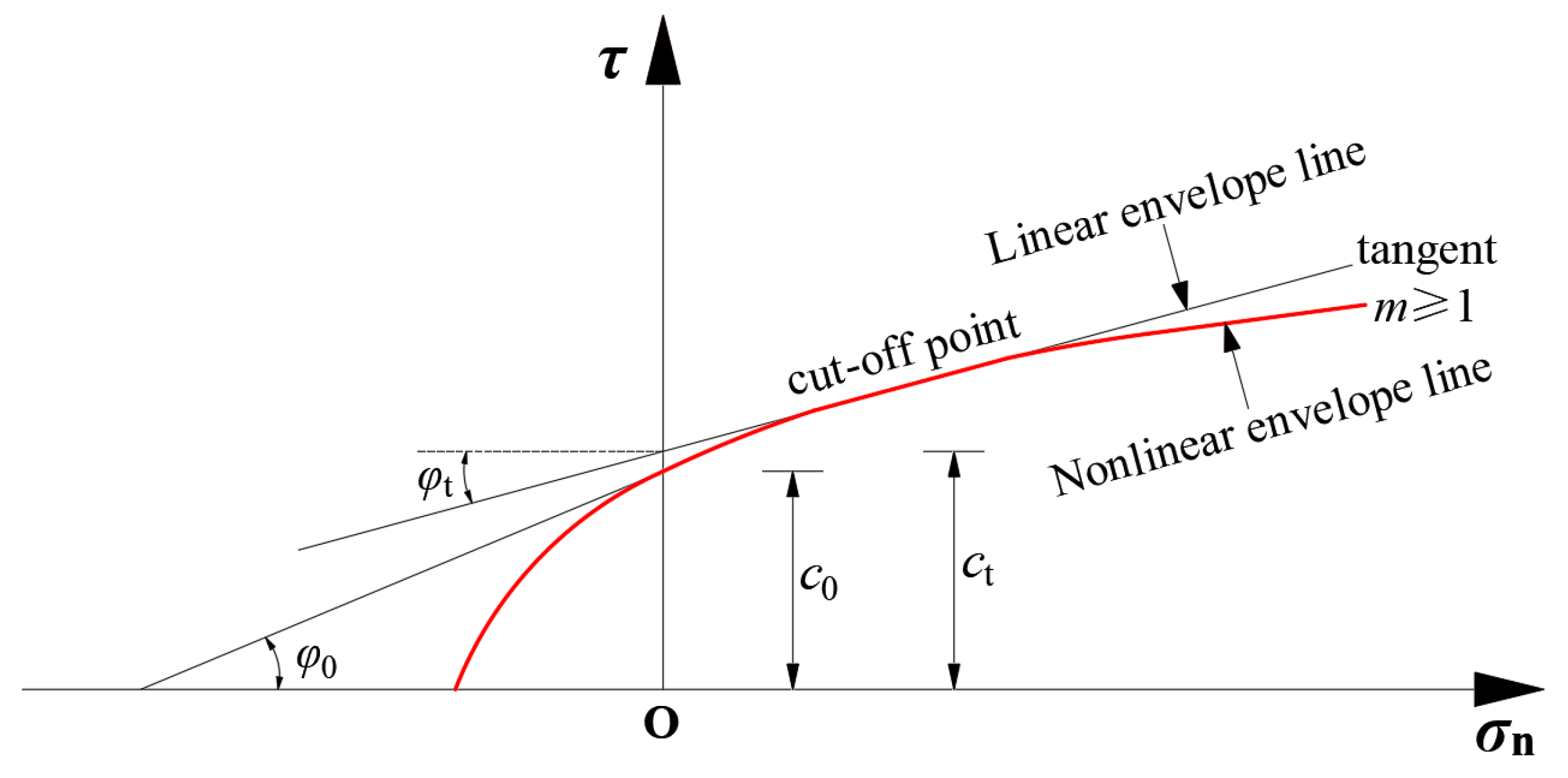
2. Nonlinear Damage Criterion

The nonlinear Mohr–Coulomb damage criteria for geotechnical materials can be expressed with reference to reference [46]:
τ = c 0 ( 1 + σ n / σ t ) 1 / m
where τ is the shear stress on the rupture surface, c0 is the initial cohesion, σn is the positive stress on the rupture surface, σt is the axial tensile stress, and m is the nonlinear coefficient, which determines the bending degree of the curve.
The curve corresponding to Equation (1) is depicted in Figure 1.
When m ≠ 1, differentiate σn as follows:
d τ d σ n = c 0 1 m 1 + σ n σ t 1 m 1 1 σ t
Simplify to obtain
d τ d σ n = c 0 m σ t 1 + σ n σ t 1 m 1
Assuming the coordinates of the point of tangency are (σn0, τ0), the equation of the tangent line is
τ τ 0 = d τ d σ n σ n = σ n 0 σ n σ n 0
where τ 0 = c 0 1 + σ n 0 σ t 1 / m .
Substitute the derivative into the equation of the tangent line, as follows:
τ c 0 1 + σ n 0 σ t 1 m = c 0 m σ t 1 + σ n 0 σ t 1 m 1 σ n σ n 0
Simplify to obtain
τ = c 0 m σ t 1 + σ n 0 σ t 1 m 1 σ n + c 0 1 + σ n 0 σ t 1 m c 0 m σ t 1 + σ n 0 σ t 1 m 1 σ n 0
Further simplification yields the equation of the tangent line for Equation (6), as follows:
τ = tan φ t σ n + c t
where ct is the intercept of tangent Equation (7), and tanφt is the slope of tangent Equation (7), which can be obtained from the slope calculation formula.
tan φ t = d τ d σ n = c 0 m σ t ( 1 + σ n σ t ) 1 m m
Join (6), (7), and (8), as follows:
c t = m 1 m c 0 m σ t tan φ t c 0 1 1 m + σ t tan φ t
According to the principle of the tangent method [47], the upper limit solution obtained by Equations (8) and (9) must be the upper limit solution of Equation (1).

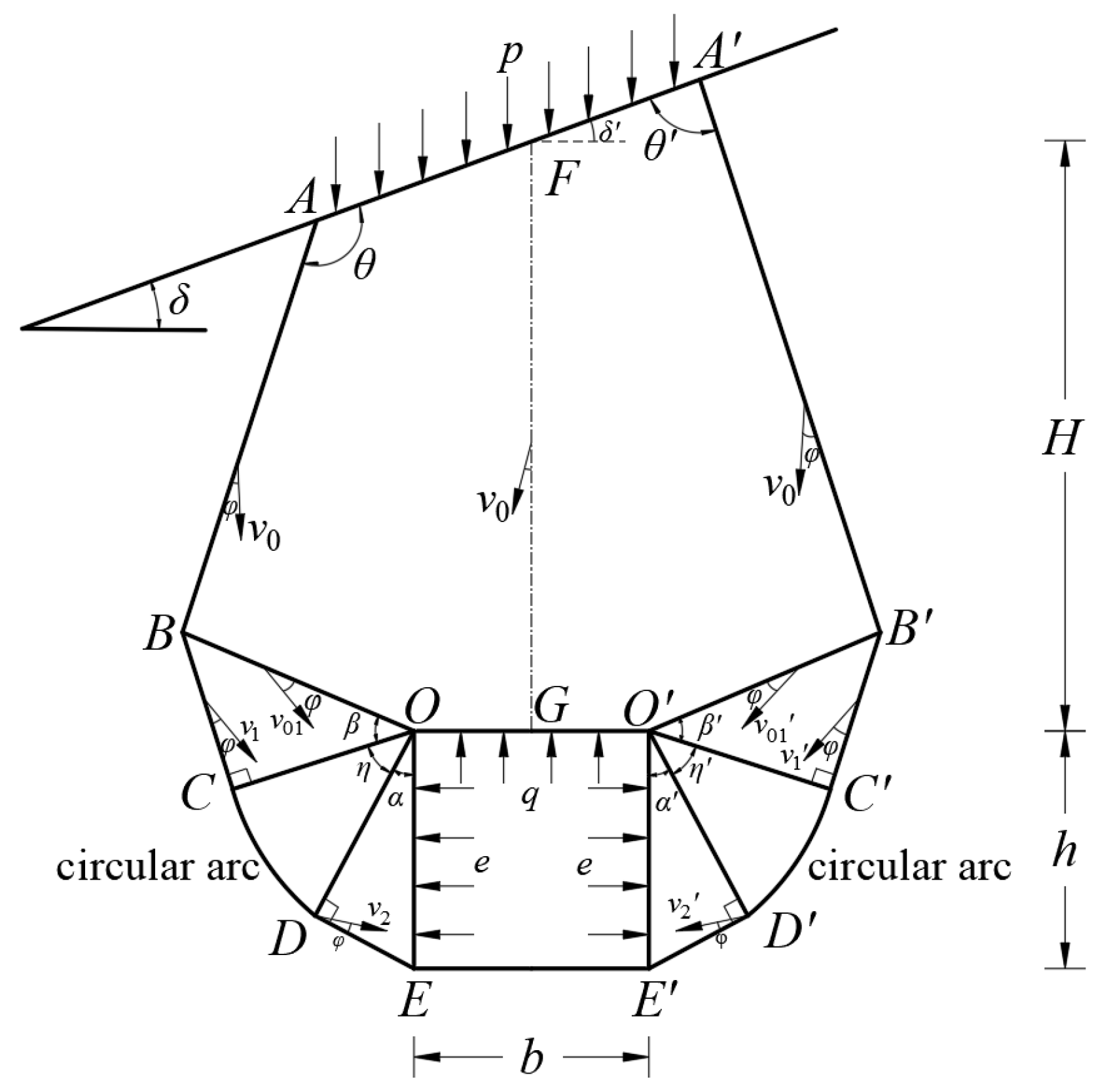
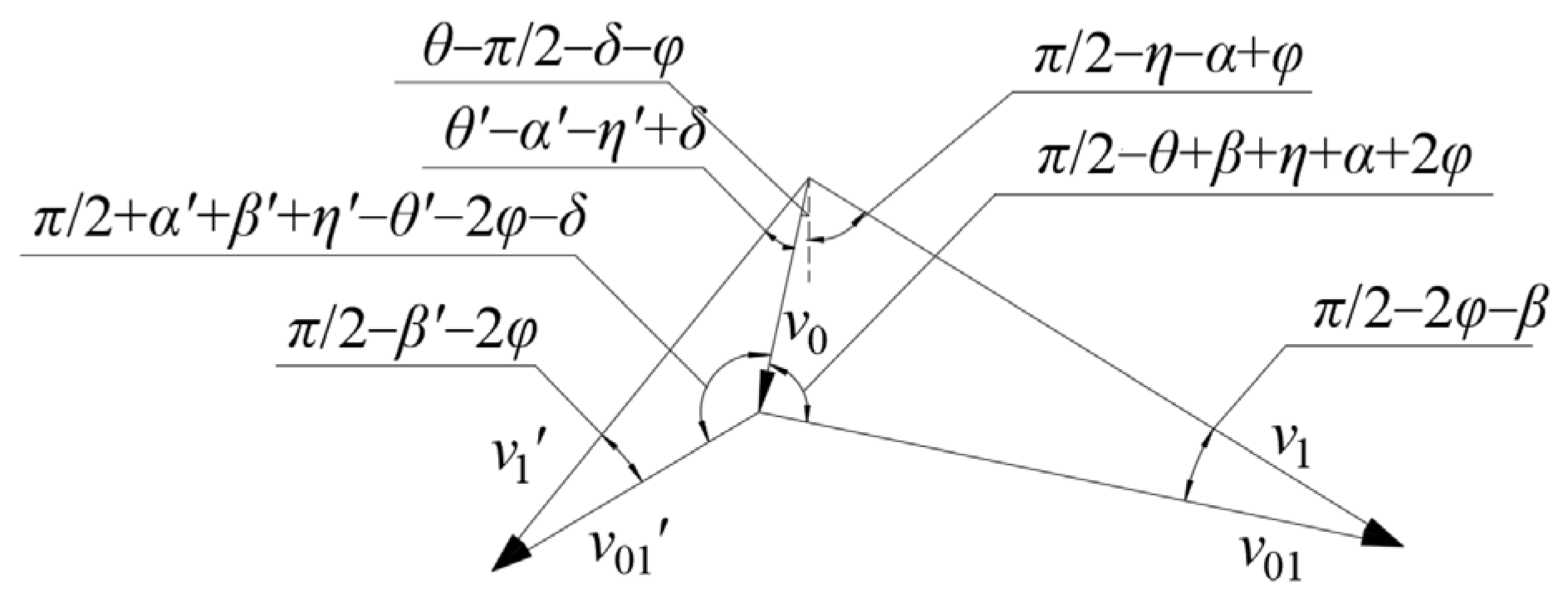
3. Destructive Mode and Velocity Field

Yang, X.L. [47] conducted a detailed derivation and demonstration of the translational failure mechanisms and velocity mechanisms for single and multiple rigid blocks under a nonlinear failure criterion, based on the upper bound limit analysis. Meanwhile, this paper makes use of the damage hypothesis, used by the Taisha base theory (Terzaghi), to calculate the surrounding rock pressure of the loose rock mass. By simplifing the tunnel section shape to a rectangle, considering the surface tilt and slope top load and ignoring the shear and expansion effect of the geotechnical materials, the arc failure mode and velocity vector diagram of shallow-buried bias tunnel is constructed (Figure 2 and Figure 3).
Assuming that the motion speed of the rigid body ABOGOBAFA (Figure 2) is v0 (v0 = 1.0), based on the velocity field closure condition and the trigonometric relationships, in the triangle formed by v0, v1, and v01, the sine theorem can be applied to obtain the following:
v 1 sin ( π / 2 + 2 φ + δ + α + β + η θ ) = v 0 sin ( π / 2 2 φ β )
Simplify to obtain
v 1 = v 0 sin ( π / 2 2 φ β ) sin ( π / 2 + 2 φ + δ + α + β + η θ )
Similarly,
v 01 = v 0 sin ( π / 2 2 φ β ) sin ( θ α η δ )
v 1 = v 0 sin π / 2 β 2 φ sin π / 2 + α + β + η θ + 2 φ δ
v 01 = v 0 sin π / 2 β 2 φ sin θ α η + δ

4. Surrounding Rock Pressure Calculation

4.1. External Force Power

The external force power is calculated as follows:
W ˙ 1 = γ v 0 cos θ π / 2 δ φ S A B O G O B A F A
W ˙ 2 = γ v 1 cos π / 2 η α + φ S B O C
W ˙ 3 = γ h 2 v 1 2 1 + tan 2 2 φ { cos ( π / 2 α + φ ) [ tan 2 φ + ( tan 2 φ cos η + sin η ) exp ( η tan 2 φ ) ] + sin ( π / 2 α + φ ) [ 1 + ( tan 2 φ sin η cos η ) exp ( η tan 2 φ ) }
W ˙ 4 = γ v 1 S D O E exp ( η tan 2 φ ) sin ( α φ )
W ˙ 5 = γ v 1 cos θ + θ α η φ π / 2 S B O C
W ˙ 6 = γ h 2 v 1 2 1 + tan 2 2 φ cos π / 2 α + φ tan 2 φ + tan 2 φ cos η + sin η exp η tan 2 φ + sin ( π / 2 α + φ ) 1 + tan 2 φ sin η cos η exp η tan 2 φ
W ˙ 7 = γ v 1 S D O E exp η tan 2 φ sin α φ
W ˙ 8 = p v 0 cos θ π / 2 δ φ l A A
W ˙ 9 = q v 0 cos θ π / 2 δ φ h
W ˙ 10 = e v 1 exp ( η tan 2 φ ) cos ( α φ ) h e v 1 exp η tan 2 φ cos α φ h
The external power W ˙ 1 , W ˙ 2 , W ˙ 5 , W ˙ 8 , W ˙ 9 for SABOGOBAFA, SBOC, SBOC, PlAA, and qh, respectively, can be calculated based on the principles described in Reference [46]. W ˙ 3 , W ˙ 4 , W ˙ 6 , W ˙ 7 are the external force power of SCOD, SDOE, SCOD, SDOE, respectively, and its calculation formula can be found in Reference [48]. W ˙ 10 is the external force power of the horizontal support force.
Where exp is an exponential function with the natural constant “e” base, for e = Kq, e is the horizontal support, q is the vertical support, and K is the ratio of horizontal and vertical support.

4.2. Internal Energy Consumption

The internal energy consumption is calculated as follows:
W ˙ A B = c t v 0 cos φ l A B
W ˙ B O = c t v 01 cos φ l B O
W ˙ B C = c t v 1 cos φ l B C
W ˙ A B = c t v 0 cos φ l A B
W ˙ B O = c t v 01 cos φ l B O
W ˙ B C = c t v 1 cos φ l B C
W ˙ C D = c t v 1 cos φ l O C sin 2 φ exp ( η tan 2 φ ) 1
W ˙ O C D = c t v 1 cos φ l O C tan 2 φ exp ( η tan 2 φ ) 1
W ˙ D E = c t v 1 cos φ exp ( η tan 2 φ ) l D E
W ˙ C D = c t v 1 cos φ l O C sin 2 φ exp η tan 2 φ 1
W ˙ O C D = c t v 1 cos φ l O C tan 2 φ exp η tan 2 φ 1
W ˙ D E = c t v 1 cos φ exp η tan 2 φ l D E
The internal energy consumption W ˙ A B , W ˙ O B , W ˙ B C , W ˙ A B , W ˙ O B , W ˙ B C for lAB, lOB, lBC, lAB, lOB, lBC, respectively, can be calculated based on the principles described in Reference [46]. W ˙ C D , W ˙ O C D , W ˙ D E , W ˙ C D , W ˙ O C D , W ˙ D E are the internal energy consumption of l C D , l O C + l O D , l D E , l C D , l O C + l O D , l D E , respectively, and its calculation formula can be found in Reference [48].

4.3. Surrounding Rock Pressure

According to the principle of virtual power, the internal energy dissipation is equal to external force work, thus obtaining the formula in this paper for calculating the perimeter rock pressure, as follows:
q = W ˙ A B + W ˙ O B + W ˙ B C + W ˙ C D + W ˙ O C D + W ˙ D E + W ˙ A B + W ˙ O B + W ˙ B C + W ˙ C D + W ˙ O C D + W ˙ D E W ˙ 1 + W ˙ 2 + W ˙ 3 + W ˙ 4 + W ˙ 5 + W ˙ 6 + W ˙ 7 W ˙ 8 v 0 cos ( θ π / 2 δ φ ) h + K v 1 exp ( η tan 2 φ ) cos ( α φ ) + v 1 exp η tan 2 φ cos α φ h

4.4. Optimum Calculation

Because the limit value of Equation (37) needs to be adjusted (α, β, η, θ, α′, β′, η′, θ′), and the value (α, β, η, θ, α′, β′, η′, θ′) must meet the requirements between the velocity vectors in the (0, π) interval. (α, β, η, θ, α′, β′, θ′) must meet certain constraints, and this can be obtained as follows:
β < π 2 2 φ , θ α β η < π 2 + 2 φ + δ , α + η θ < δ β < π 2 2 φ , θ α β η < π 2 + 2 φ δ , α + η θ < δ
Under the constraints of Equation (38), Equation (37) sets an initial vector in the program and then constantly changes the value of the initial vector (α, β, η, θ, α′, β′, η′, θ′), calculating the maximum q value as the upper solution of the surrounding rock pressure in the stable limit state of the surrounding rock in the circular arc failure mode. The above process can be implemented through the built-in optimization toolbox in MATLAB (R2022a) software. The detailed steps can be found in the Fmincon function chapter in Reference [49], which will not be repeated in this paper.

5. Comparative Analysis with Existing Results

To verify the reliability of the calculation method of the arc failure mode mentioned above, take the shallow tunnel burial depth of the slope section H = 20 m, rectangular tunnel height h = 10 m, span b = 10 m, bulk density of surrounding rock γ = 20 kN/m3, uniaxial tensile strength σt = 30 kPa, cohesion of surrounding rock c0 = 10 kPa, angle of internal friction in the surrounding rock φ = 18°, and slope surface inclination δ = 18°, the slope top load isp = 0 kPa, the ratio of horizontal support force to vertical support force of surrounding rock K = 0.4, 0.5, 0.6, 0.8, 1.0, and 1.2, and the nonlinear coefficients m = 1.0, 1.1, 1.2, and 1.4. To facilitate comparative analysis, the calculated angle of internal friction of the surrounding rock φc and friction angle θ on both sides of the soil column at the top plate refer to the physical and mechanical indexes of the surrounding rock in Reference [17], i.e., grade VI surrounding rock φc = 30°~40° and θ = 0.5 φc; the calculation results obtained by different methods are demonstrated in Table 1.

6. Example Analysis

The study focuses on a shallow-buried, eccentrically loaded tunnel with a relatively long alignment. The terrain along the tunnel route exhibits significant undulations, with an overall topography that is lower in the north and higher in the south. The influence of groundwater is not considered in this analysis. The geotechnical parameters and measured values of the surrounding rock pressure for the shallow-buried, eccentrically loaded tunnel are obtained from Reference [27].
Charles, J. A. et al. [52] and Jiang, J. C. et al. [53] have theoretically and experimentally demonstrated that the non-linear coefficient m for classic geotechnical materials ranges from 1.0 to 2.0. Luo, W. et al. [46] conducted theoretical calculations to investigate the effects of surface surcharge loads ranging from 0 to 200 kPa and burial depth ratios from 1.0 to 2.0 on the surrounding rock pressure and failure modes of shallow-buried tunnels. Fu, H. L. et al. [54] theoretically analyzed the influence of different axial tensile stresses and initial cohesive force values ranging from 6 to 24 kPa on the surrounding rock pressure. Based on practical applications and existing research findings, the parameter ranges for the analysis in this study are presented in Table 2.

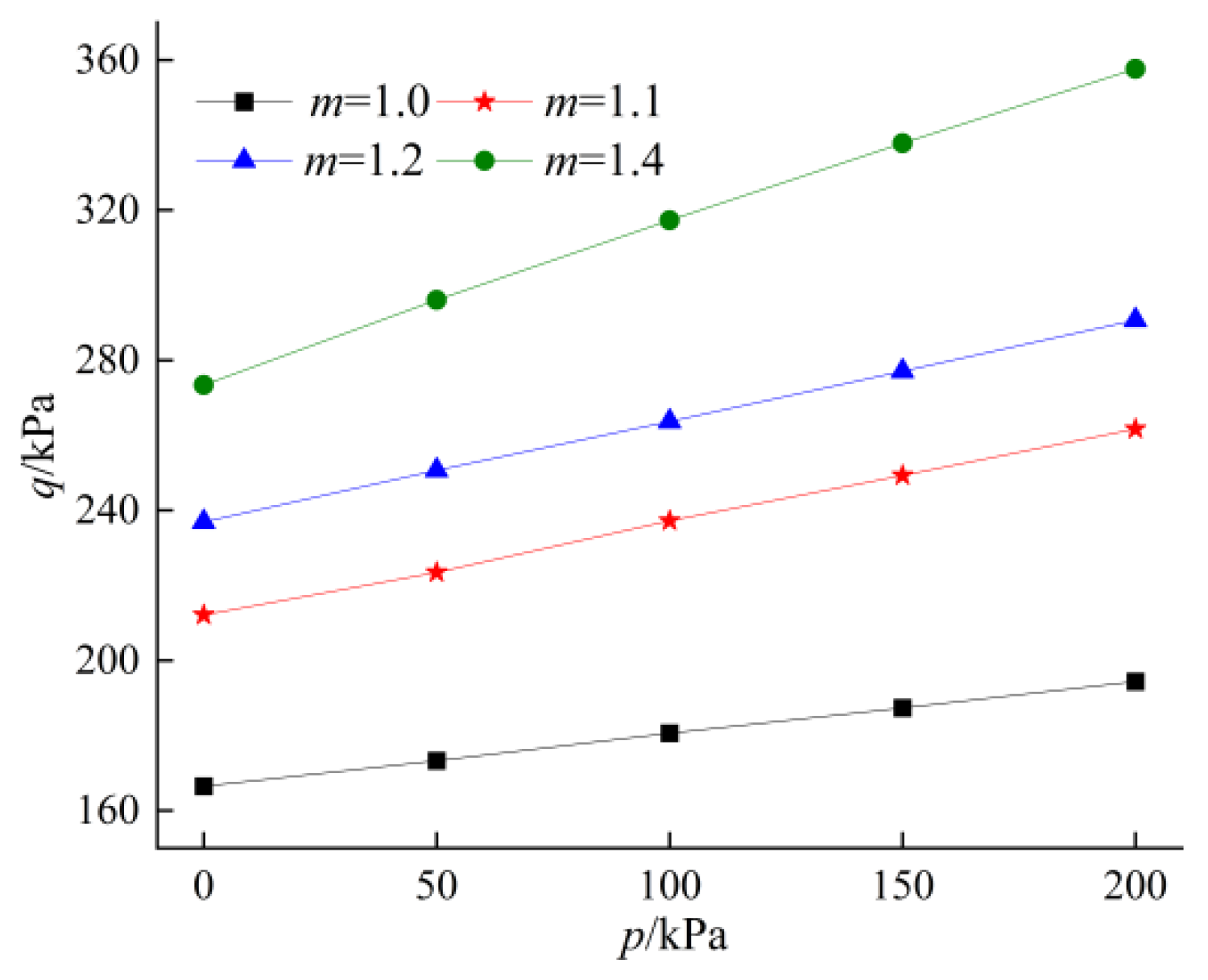
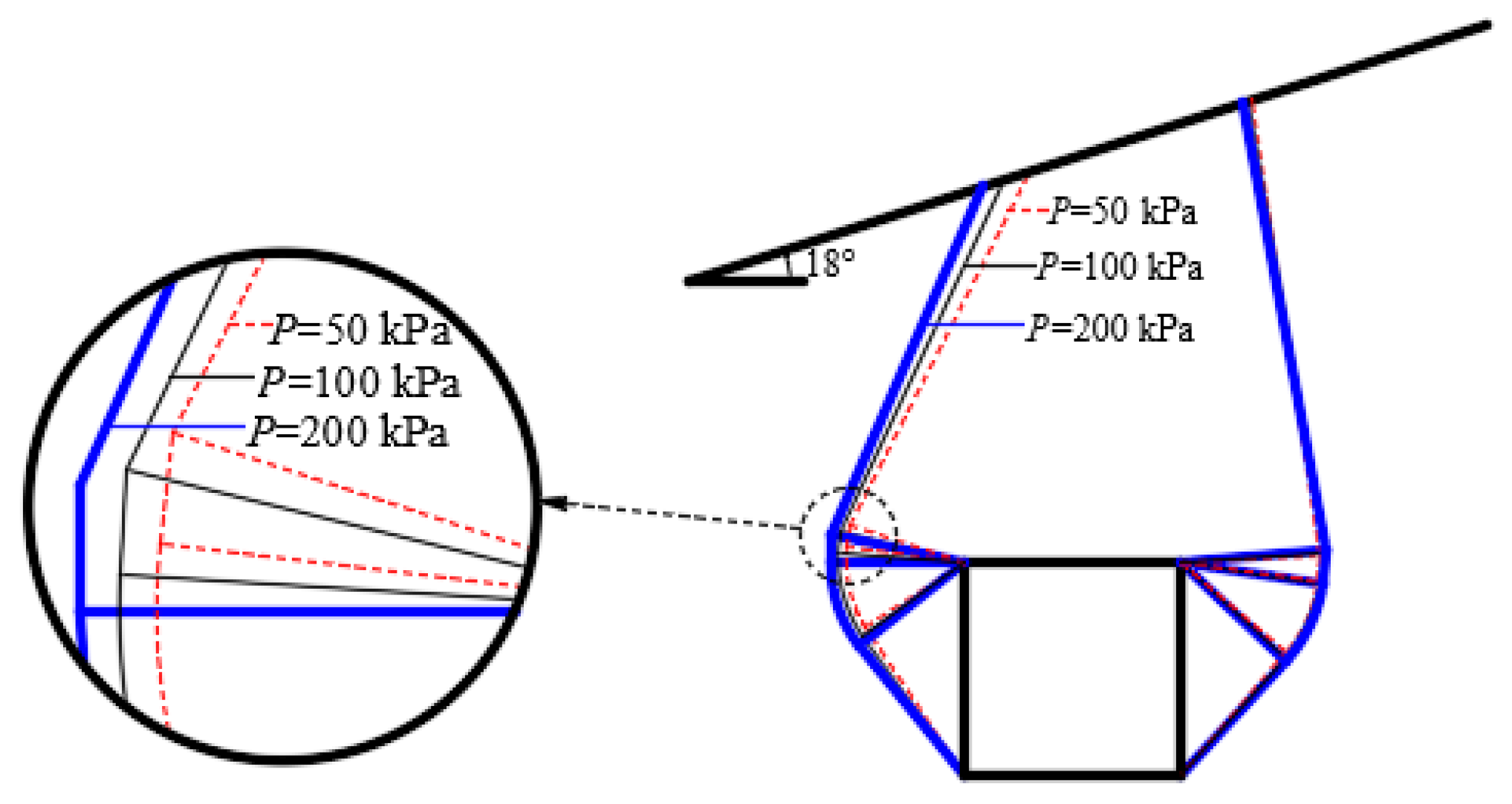
6.1. Influence of Slope Top Load

When the shallow-tunnel burial depth of the slope section H = 20 m, rectangular tunnel height h = 10 m, span b = 10 m, bulk density of surrounding rock γ = 20 kN/m3, uniaxial tensile strength σt = 30 kPa, cohesion of surrounding rock c0 = 10 kPa, angle of internal friction in the surrounding rock φ = 18°, slope surface inclination δ = 18°, ratio of horizontal support force to vertical support force of surrounding rock K = 1.0, nonlinear coefficients m = 1.0, 1.1, 1.2, 1.4, so that the slope top load p = 0~200 kPa, the changes in surrounding rock pressure and failure mode of the shallow-buried tunnel are illustrated in Figure 4 and Figure 5.
From Figure 4, it can be seen that with the increase in the load on the top of the slope, the perimeter rock pressure increases significantly. p varies from 0 kPa to 200 kPa, and when m = 1.0, the increased value of the perimeter rock pressure reaches a minimum of 28 kPa; when m = 1.4, the increased value of the perimeter rock pressure reaches a maximum of 84 kPa, and m varies from 1.0 to 1.4; when p = 0 kPa, the increased value of the perimeter rock pressure reaches a minimum of 107 kPa; when p = 200 kPa, the increased value of the perimeter rock pressure reaches a maximum of 163 kPa, which indicates that the larger the load at the top of the slope is affected by the nonlinear coefficient more significantly. It can be inferred that, in actual construction, especially in loess sedimentation areas, the unique geological conditions make the surrounding rock more susceptible to instability and deformation under the external loads from traffic, equipment, and structures on the tunnel roof. These factors adversely affect the stability of the surrounding rock. Therefore, in such regions, it is imperative to strictly control engineering activities within the tunnel roof area to prevent the occurrence of tunnel collapse and other disasters. As can be seen from Figure 5, when the load on the top of the slope increases, the tunnel damage is shifted towards the shallower side of the slope. Consequently, the engineering protection of the shallower side should be emphasized.

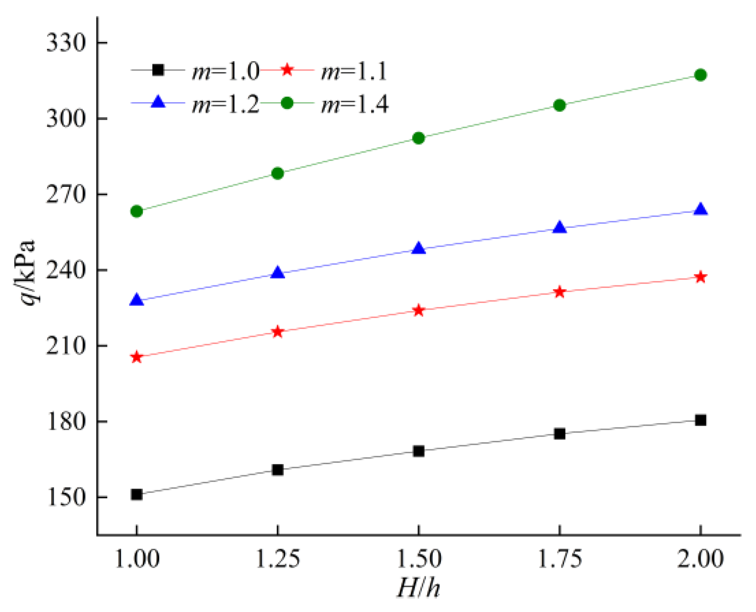
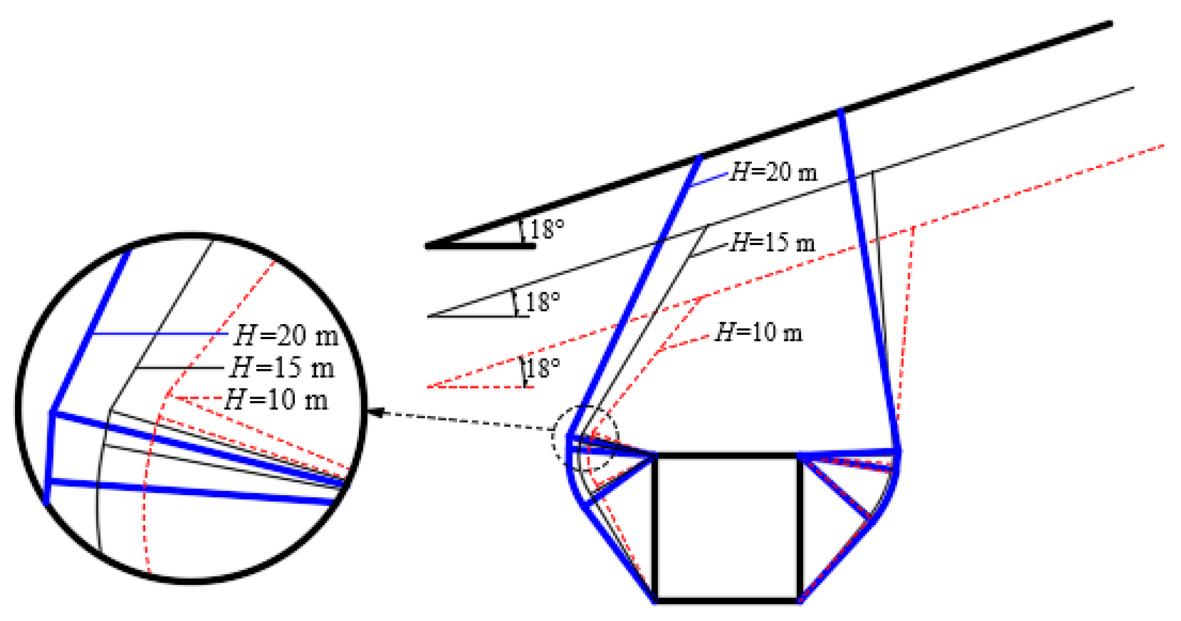
6.2. Effect of Buried Depth Ratio

When the shallow-tunnel burial depth of the slope section H = 20 m, rectangular tunnel height h = 10 m, span b = 10 m, bulk density of surrounding rock γ = 20 kN/m3, uniaxial tensile strength σt = 30 kPa, cohesion of surrounding rock c0 = 10 kPa, angle of internal friction in the surrounding rock φ = 18°, slope surface inclination δ = 18°, ratio of horizontal support force to vertical support force of surrounding rock K = 1.0, nonlinear coefficients m = 1.0, 1.1, 1.2, 1.4, the slope top load is p = 100 kPa, so that the buried depth ratio (the ratio of the buried depth of a shallow tunnel to the height of the tunnel) H/h = 1.0~2.0, and the variations in the peripheral rock pressures and damage modes of the shallow tunnel are shown in Figure 6 and Figure 7.
As is shown in Figure 6, with the increase in the depth of burial ratio, the perimeter rock pressure increases significantly. H/h changes from 1.0 to 2.0 when m = 1.0, and the perimeter rock pressure increases to a minimum of 29 kPa; when m = 1.4, the perimeter rock pressure increases to a maximum of 54 kPa; when m changes from 1.0 to 1.4 and H/h = 1.0, the perimeter rock pressure increases to a minimum of 112 kPa; and when H/h = 2.0, the perimeter rock pressure increases to a maximum of 136 kPa, which indicates that the larger the burial depth ratio, the more significantly it is affected by the nonlinear coefficient. It can be seen that, on the basis of the determined tunnel cross-section size, adjustment of the geotechnical nonlinear coefficient and other methods of increasing the stability of the tunnel surrounding rock can be used to reduce the shallow-tunnel depth or grouting reinforcement. It is shown from Figure 7 that when the burial depth ratio increases, the damage of the shallow-buried tunnel is shifted toward the shallower side of the slope. Therefore, in engineering practice, reinforcement measures can be taken in advance for the geotechnical body on the shallower side of the burial depth to prevent the potential danger caused by the offset.

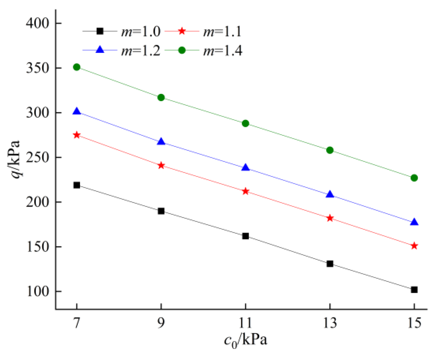
6.3. Effect of Cohesion

When the shallow-tunnel burial depth of the slope section H = 20 m, rectangular tunnel height h = 10 m, span b = 10 m, bulk density of surrounding rock γ = 20 kN/m3, uniaxial tensile strength σt = 30 kPa, cohesion of surrounding rock c0 = 7~15 kPa, angle of internal friction in the surrounding rock φ = 18°, slope surface inclination δ = 18°, ratio of horizontal support force to vertical support force of surrounding rock K = 1.0, nonlinear coefficients m = 1.0, 1.1, 1.2, 1.4, and slope top load p = 100 kPa, the variations in the pressure and damage patterns of the surrounding rock in shallow-buried tunnels are presented in Figure 8 and Figure 9.
Figure 8 indicates that when the nonlinear coefficient m is certain, the surrounding rock pressure shows a significant decreasing trend with the increase in cohesion. When the cohesion c 0 is certain, the surrounding rock pressure increases significantly with the increase in the nonlinear coefficient. It can be seen that the surrounding rock pressure calculated by the nonlinear criterion is very sensitive to the change in the cohesive force. Analyzed from the perspective of the principle of virtual work, the cohesive force increases, the internal energy consumption also increases, and the support reaction force required by the surrounding rock will decrease. As can be seen from Figure 9, with the decrease in cohesive force, the damage surface has an obvious tendency to extend outward, and the area of the shear zone increases. Therefore, in the case of poor surrounding rock conditions, the tunnel cross-section construction is prone to forming a large plastic zone. Based on the monitoring data obtained during the construction stage and the characteristics of the surrounding rock, measures such as the use of spraying anchors and grouting reinforcement can be employed to protect shallow-buried, eccentrically loaded tunnels, thereby enhancing the stability of the surrounding rock.

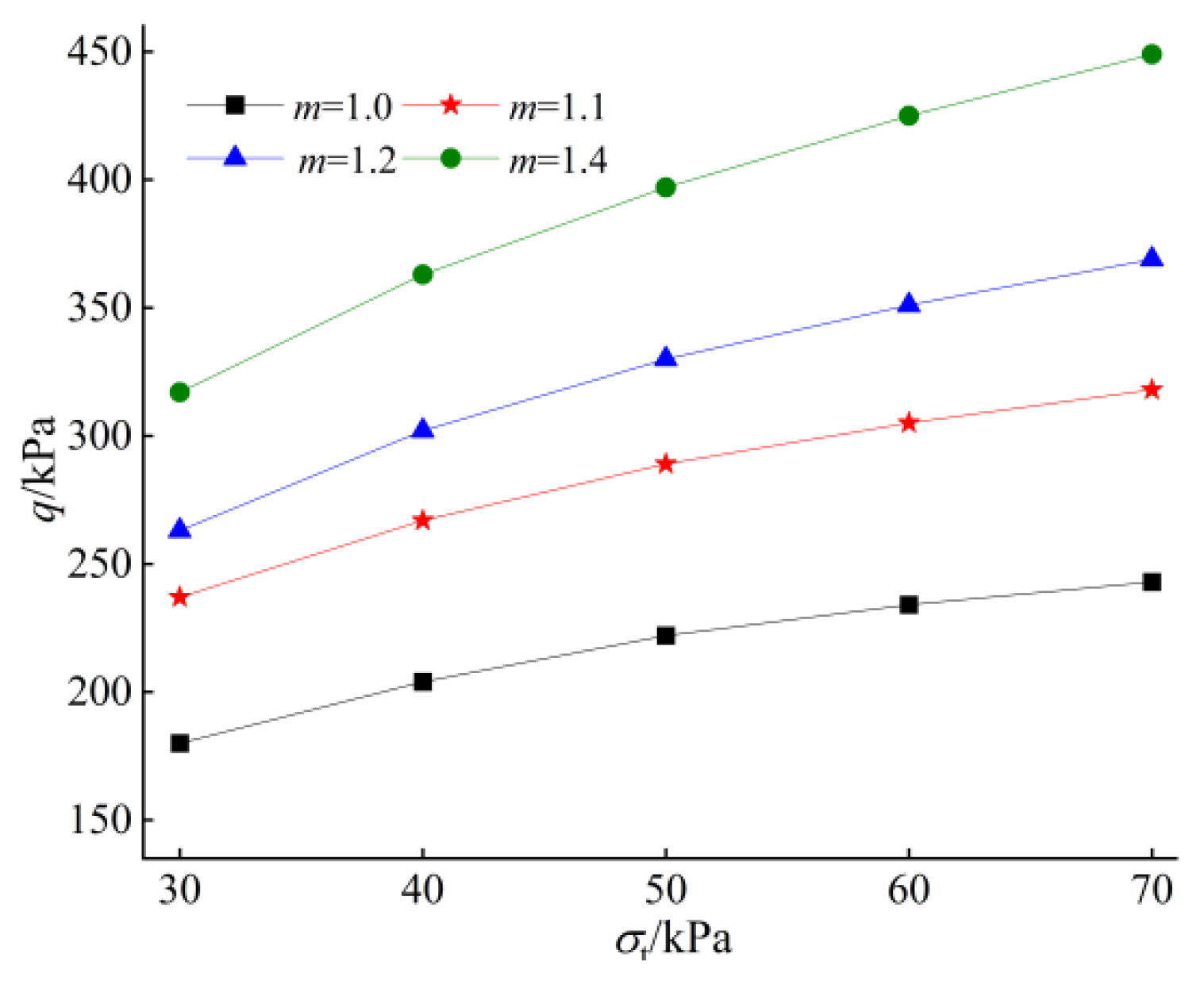
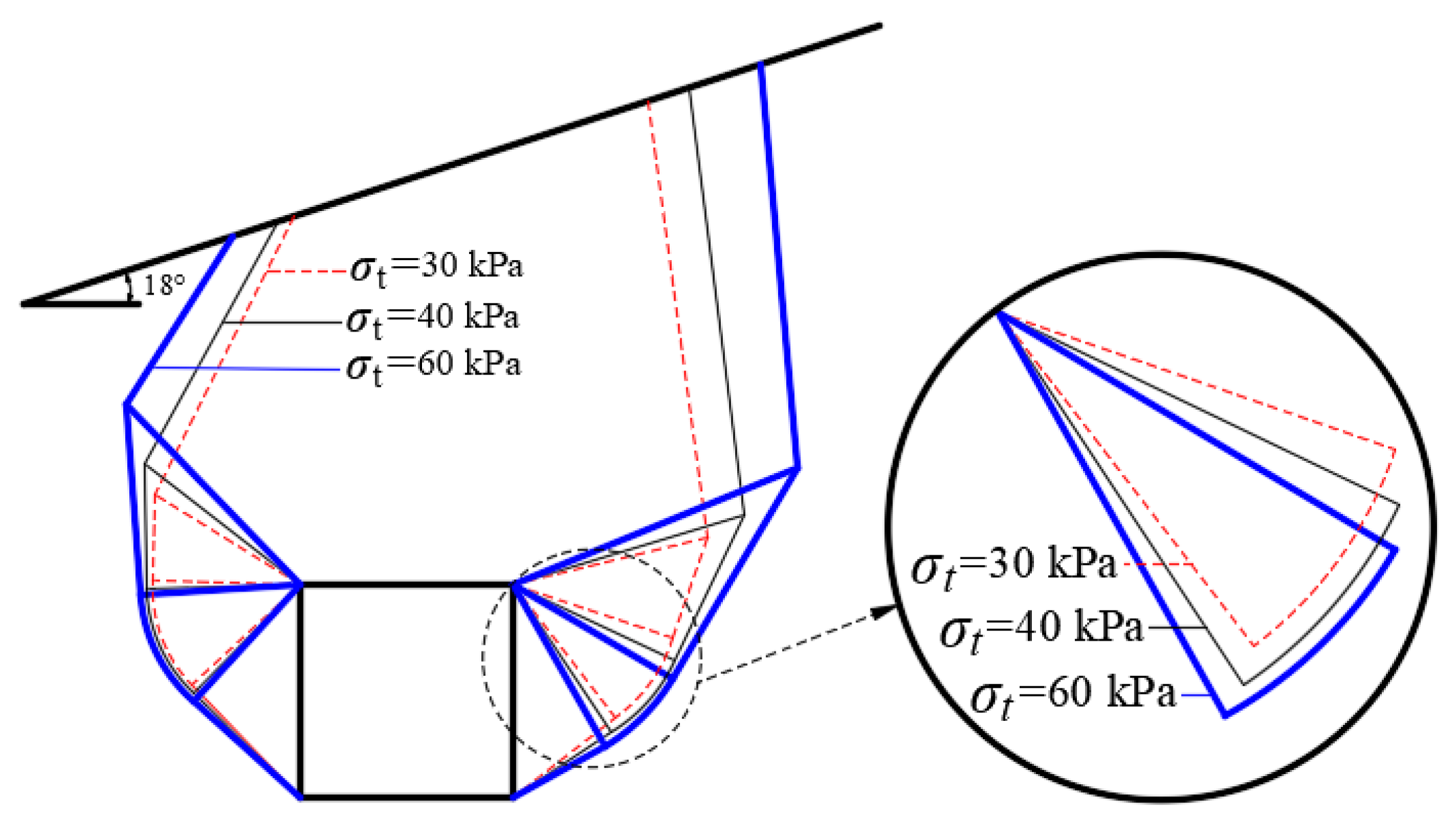
6.4. Influence of Axial Tensile Stress

When the shallow-tunnel burial depth of the slope section H = 20 m, rectangular tunnel height h = 10 m, span b = 10 m, bulk density of surrounding rock γ = 20 kN/m3, cohesion of surrounding rock c0 = 30 kPa, axial tensile stress σt = 30~70 kPa, internal friction angle of surrounding rock φ = 18°, slope surface inclination angle δ = 18°, ratio of horizontal support force to vertical support force of surrounding rock K = 1.0, nonlinear coefficients m = 1.0, 1.1, 1.2, 1.4, and order slope top load p = 100 kPa, the variations in pressure and damage patterns of the surrounding rock in shallow-buried tunnels are shown in Figure 10 and Figure 11.
As illustrated in Figure 10, with the increase in axial tensile stress, the surrounding rock pressure increases significantly. σt changes from 30 kPa to 70 kPa when m = 1.0, and the value of the increase in the surrounding rock pressure reaches a minimum of 53 kPa; when m = 1.4, the value of the increase in the surrounding rock pressure reaches a maximum of 132 kPa. When m changes from 1.0 to 1.4, when σt = 30 kPa, the value of the increase in the surrounding rock pressure reaches a minimum of 137 kPa; and when σt = 70 kPa, indicating that the larger the axial tensile stress is affected by the nonlinear coefficient more significantly. As evidenced by Figure 11, it can be observed that with the increase in axial tensile stress, the damage surface has an obvious tendency to extend outward, and the area of the shear zone increases, which indicates that the plastic zone caused by the bias pressure will increase in the excavation process. It can be inferred that the axial tensile stress significantly affects both the magnitude of the surrounding rock pressure and the location of the failure surface. Therefore, numerical simulation methods can be employed to analyze the distribution patterns of stress and displacement within the surrounding rock. For weak surrounding rock, it is essential to implement engineering support measures in advance and to optimize the support scheme and construction sequence in a timely manner to prevent collapse caused by insufficient support force.

7. Conclusions

(1)
When conducting the support design calculations for the surrounding rock in the circular arc failure mode of shallow-buried tunnels in slope sections, the upper-bound limit analysis method demonstrates significant advantages. Compared with the code-based method and the limit equilibrium method, the upper-bound limit analysis method yields the smallest value of surrounding rock pressure. Additionally, it effectively reduces the design requirements and engineering costs of the support structure, thereby achieving higher economic benefits.
(2)
The enclosed rock pressure under the circular damage mode of shallow-buried tunnel in the sloping section increases with the increasing value of the geotechnical nonlinear coefficient m. When the value of m is larger, the effect on the enclosing rock pressure is more significant; the nonlinear damage criterion cannot be crudely simplified to a linear criterion; otherwise, it will underestimate the upper limit value of the enclosing rock pressure, and decreasing the ratio of the horizontal support force to the vertical support force K will cause a significant increase in the enclosing rock pressure.
(3)
The increase in slope crest load and the enlargement of the burial depth ratio have a significantly greater impact on the soil on the shallow-buried side than on the deep-buried side. This can easily cause the circular arc failure mode of the shallow-buried tunnel to shift towards the shallow-buried side, while also increasing the stress concentration in the surrounding rock on the shallow-buried side and reducing the overall stability of the tunnel. In the actual project, for special geological conditions such as loess sedimentation areas, reinforcement measures can be taken in advance for the rock and soil body on the shallow side to prevent engineering accidents caused by the offset.
(4)
An increase in axial tensile stress and a decrease in cohesion will cause the damage surface to extend outward and the area of shear zone to increase. The increase in axial tensile stress will cause the surrounding rock pressure to increase, while the increase in cohesive force will lead the surrounding rock pressure to decrease. When the surrounding rock conditions are poor, the surrounding rock of the tunnel is prone to forming a large plastic zone, which may pose safety hazards. By employing numerical simulation and based on the surrounding rock conditions and the monitoring of data obtained during the construction phase, measures such as shotcrete-anchorage support and grouting reinforcement can be implemented to enhance the stability of shallow-buried, eccentrically loaded tunnels.
(5)
The current study on the nonlinear stability analysis of shallow-buried, eccentrically loaded tunnels in circular arc failure mode is limited to the scenario of simple eccentric loading. Future research will extend to the stability analysis of tunnels under coupled hydrological actions and the reinforcement of tunnel stability under the influence of multiple complex factors. Additionally, in-depth explorations will be conducted in conjunction with practical engineering cases.

Author Contributions

Conceptualization, W.L.; methodology, W.L. and G.X.; software, Z.T.; validation, W.L. and G.X.; formal analysis, G.X. and Z.T.; investigation, X.L. and H.W.; resources, W.L. and J.C.; data curation, X.L. and H.W.; writing—original draft preparation, G.X. and Z.T.; writing—review and editing, G.X.; visualization, Z.T.; supervision, W.L. and X.L.; project administration, J.C.; funding acquisition, W.L. and J.C. All authors have read and agreed to the published version of the manuscript.

Funding

Funding for this research was provided by Project (52268063, 52108320), supported by the National Natural Science Foundation of China; Project (20224BAB204063), supported by the Natural Science Foundation of Jiangxi Province; Project (2021H0042), supported by the Science and Technology Project of the Jiangxi Provincial Transportation Department; and Project (YC2024-S393, YC2023-S461), supported by the Special Funding Program for Graduate Student Innovation in Jiangxi Province.

Institutional Review Board Statement

This study does not involve research on human subjects or animals.

Informed Consent Statement

This study does not involve human research.

Data Availability Statement

Data is unavailable due to privacy.

Conflicts of Interest

The authors declare no conflicts of interest.

References

  1. Zhao, J.; Tan, Z.; Zhang, B.; Wang, F. Stress-Release Technology and Engineering Application of Advanced Center Drifts in a Super-Deep Soft-Rock Tunnel: A Case Study of the Haba Snow Mountain Tunnel. Rock Mech. Rock Eng. 2024, 57, 7103–7124. [Google Scholar] [CrossRef]
  2. Zhao, Y.; Du, Y.; Yan, Q. Challenges of, Progress in, and Prospects of Ultra-Long Deep Tunnels in the Extremely Complex Environment of the Qinghai–Tibet Plateau. Engineering 2024, 44, 162–183. [Google Scholar] [CrossRef]
  3. Zhou, X.; He, Y.; Zhang, W.; Liu, D. Multifractal Characteristics and Displacement Prediction of Deformation on Tunnel Portal Slope of Shallow Buried Tunnel Adjacent to Important Structures. Buildings 2024, 14, 1662. [Google Scholar] [CrossRef]
  4. Wang, Y.; Li, J.; Wang, Z.F.; Chang, H. Structural failures and geohazards caused by mountain tunnel construction in fault zone and its treatment measures: A case study in Shaanxi. Eng. Fail. Anal. 2022, 138, 106386. [Google Scholar] [CrossRef]
  5. Wang, M.; Zhang, Z.; Ren, L.; Zhang, R.; Zheng, L.; Zhang, L.; Zhang, Z.; Xie, J.; Liu, X. Analysis of Rock Mass Parameters and Plastic Zone of a Tunnel in Southwest Mountainous Area. KSCE J. Civ. Eng. 2023, 27, 5448–5459. [Google Scholar] [CrossRef]
  6. Zhang, K.; Zheng, W.; Liao, Z.; Xie, H.; Zhou, C.; Chen, S.; Zhu, J. Risk assessment of ground collapse along tunnels in karst terrain by using an improved extension evaluation method. Tunn. Undergr. Space Technol. 2022, 129, 104669. [Google Scholar] [CrossRef]
  7. Wu, B.; Zhu, R.; Wang, W.; Zeng, J.; Liu, C. Quantitative analysis of construction risks in shallowly buried biased tunnel portal section. Sci. Rep. 2024, 14, 23246. [Google Scholar] [CrossRef]
  8. Li, J.; Xu, F.; Zheng, X.; Liu, B.; Bai, T.; Tang, Q. Study on the Fracture Evolution Characteristics of Existing Defect Lining under Unsymmetrical Load. Sustainability 2023, 15, 9531. [Google Scholar] [CrossRef]
  9. Wu, H.; Fan, F.; Yang, X.; Wang, Z.; Lai, J.; Xie, Y. Large deformation characteristics and treatment effect for deep bias tunnel in broken phyllite: A case study. Eng. Fail. Anal. 2022, 135, 106045. [Google Scholar] [CrossRef]
  10. Kong, F.; Lu, D.; Ma, Y.; Li, J.; Tian, T. Analysis and intelligent prediction for displacement of stratum and tunnel lining by shield tunnel excavation in complex geological conditions: A case study. IEEE Trans. Intell. Transp. Syst. 2022, 23, 22206–22216. [Google Scholar] [CrossRef]
  11. Gao, J.; Guo, W.; Ma, M.; Hou, Y.; Zhang, R.; Zeng, L.; Zhang, C.; Xu, Y.; Wei, X.; Cao, C. Study on Temperature Distribution along the Ultra-Long Underwater Tunnel: Based on the Long-Term Measured Results of the Shanghai Yangtze River Tunnel. Buildings 2023, 13, 1804. [Google Scholar] [CrossRef]
  12. Zhou, Z.; Ma, J.; Lu, T.; Li, G.; Fang, S.; Tan, T. An evaluation method for visual search stability in urban tunnel entrance and exit sections based on markov chain. IEEE Access 2020, 8, 68559–68569. [Google Scholar] [CrossRef]
  13. He, Z.; Li, C.; He, Q.; Liu, Y.; Chen, J. Numerical parametric study of countermeasures to alleviate the tunnel excavation effects on an existing tunnel in a shallow-buried environment near a slope. Appl. Sci. 2020, 10, 608. [Google Scholar] [CrossRef]
  14. Mao, Z.; An, N.; Li, R.; Xu, L.; Wu, H. Treatment Effect Analysis on Shallow Buried Bias Slope Section of Tunnel Based on Fuzzy Comprehensive Evaluation. Geotech. Geol. Eng. 2020, 38, 4463–4477. [Google Scholar] [CrossRef]
  15. Li, G.J.; Qu, Y.; Lu, G.S.; Liu, J.S. Surrounding Rock Pressure of Tunnel with Small Clear Distance under Complex Unsymmetrical Loading: Calculation and Parameter Impacts. J. Chang. River Sci. Res. Inst. 2020, 37, 133–138. [Google Scholar]
  16. Chen, H.J.; Liu, X.R.; Du, L.B.; Liu, K. Sliding Failure Mechanism and Its Criterion of Unsymmetrical Loading Shallow Buried Tunnel in Layered Rock Mass. Chin. J. Undergr. Space Eng. 2021, 17, 1733–1741. [Google Scholar]
  17. JTG 3370.1-2018; Specifications for Design of Highway Tunnels Section 1 Civil Engineering. Ministry of Transport of the People’s Republic of China: Beijing, China, 2018.
  18. Man, J.; Zhou, M.; Zhang, D.; Huang, H.; Chen, J. Face stability analysis of circular tunnels in layered rock masses using the upper bound theorem. J. Rock Mech. Geotech. Eng. 2022, 14, 1836–1848. [Google Scholar] [CrossRef]
  19. Wu, W.; Liu, X.; Guo, J.; Sun, F.; Huang, X.; Zhu, Z. Upper limit analysis of stability of the water-resistant rock mass of a Karst tunnel face considering the seepage force. Bull. Eng. Geol. Environ. 2021, 80, 5813–5830. [Google Scholar] [CrossRef]
  20. Senent, S.; Yi, C.; Jimenez, R. An upper bound solution for tunnel face stability analysis considering the free span. Tunn. Undergr. Space Technol. 2020, 103, 103515. [Google Scholar] [CrossRef]
  21. Wang, C.; Hou, J.; Ye, X.W.; Chen, Y.M.; Chu, W.J.; Xie, T.Y. A 3D torus-slice model for limit equilibrium analysis of shield tunnel face under soil arching effect. Eng. Fail. Anal. 2023, 146, 107148. [Google Scholar] [CrossRef]
  22. Goh AT, C.; Zhang, W.; Zhang, Y.; Xiao, Y.; Xiang, Y. Determination of earth pressure balance tunnel-related maximum surface settlement: A multivariate adaptive regression splines approach. Bull. Eng. Geol. Environ. 2018, 77, 489–500. [Google Scholar] [CrossRef]
  23. Atkinson, J.H.; Potts, D.M. Stability of Shallow Tunnel in Cohesionless Soil. Géotechnique 1977, 27, 203–215. [Google Scholar] [CrossRef]
  24. Soubra, A.H.; Dias, D.; Emeriault, F. Three-dimensional face stability analysis of circular tunnels by a kinematical approach. Geotechqiuue 2008, 30, 894–901. [Google Scholar]
  25. Mollon, G.; Dias, D.; Soubra, A.H. Probabilistic analysis and design of circular tunnels against face stability. Int. J. Geomech. 2009, 9, 237–249. [Google Scholar] [CrossRef]
  26. Zhao, L.H.; Li, L.; Dan, H.C.; Luo, S.P.; Ren, D.Y. Discussion on Generalized Tangential Method Led in Nonlinear Failure Criterion in Upper Boundary Limit Analysis. J. Chang. River Sci. Res. Inst. 2010, 27, 34–39. [Google Scholar]
  27. Luo, W. Stability Analysis and Reliability Research on the Shallow Tunnel under Unsymmetrical Pressure. Ph.D. Thesis, Central South University, Changsha, China, 2014. [Google Scholar]
  28. Xiang, Y.; Song, W. Upper-bound limit analysis of shield tunnel stability in undrained clays using complex variable solutions for different ground-loss scenarios. Int. J. Geomech. 2017, 17, 04017057. [Google Scholar] [CrossRef]
  29. Khezri, N.; Mohamad, H.; Fatahi, B. Stability assessment of tunnel face in a layered soil using upper bound theorem of limit analysis. Geomech. Eng. 2016, 11, 471–492. [Google Scholar] [CrossRef]
  30. Li, D.J.; Zhao, L.H.; Cheng, X.; Zuo, S.; Jiao, K.F. Upper-bound limit analysis of passive failure of a 3D shallow tunnel face under the bidirectional inclined ground surfaces. Comput. Geotech. 2020, 118, 103310. [Google Scholar] [CrossRef]
  31. Çelik, S. Comparison of Mohr-Coulomb and Hardening Soil Models’ Numerical Estimation of Ground Surface Settlement Caused by Tunneling. J. Inst. Sci. Technol. Fen Bilim. Estitüsü Derg. 2017, 7, 95–102. [Google Scholar] [CrossRef]
  32. Sheng, Y.; Zou, J.; Dong, Y.; Chen, G. Novel perturbation solutions for deep-buried non-circular tunnels under biaxial in situ stress field based on Mohr-Coulomb criterion. Appl. Math. Model. 2022, 110, 408–440. [Google Scholar] [CrossRef]
  33. Li, W.; He, P.; Wang, G.; Zheng, W.; Fan, K.; Wang, L.; Zheng, C. Elastoplastic Solution for Tunnel Composite Support Structures Based on Mohr–Coulomb Criterion. Buildings 2024, 14, 3657. [Google Scholar] [CrossRef]
  34. Huang, F.; Wang, Y.; Xu, J.; Pan, Q.; Wang, D. Three-dimensional stability analysis of slurry trench based on Mohr-Coulomb nonlinear failure criterion. KSCE J. Civ. Eng. 2022, 26, 5038–5048. [Google Scholar] [CrossRef]
  35. Li, D.J.; Zhao, L.H.; Yang, F.; Xiao, C. Three-dimensional stability analysis of passive failure on shallow tunnel facebased on the nonlinear failure criterion. Chin. J. Rock Mech. Eng. 2016, 35, 743–752. [Google Scholar]
  36. Xu, J.; Yang, X. Seismic stability of 3D soil slope reinforced by geosynthetic with nonlinear failure criterion. Soil Dyn. Earthq. Eng. 2019, 118, 86–97. [Google Scholar] [CrossRef]
  37. Zhang, D.B.; Ma, Z.Y.; Yu, B.; Yin, H.D. Upper bound solution of surrounding rock pressure of shallow tunnel under nonlinear failure criterion. J. Cent. South Univ. 2019, 26, 1696–1705. [Google Scholar] [CrossRef]
  38. Cabezas, R.; Vallejos, J. Nonlinear criterion for strength mobilization in brittle failure of rock and its extension to the tunnel scale. Int. J. Min. Sci. Technol. 2022, 32, 685–705. [Google Scholar] [CrossRef]
  39. Cattari, S.; Calderoni, B.; Caliò, I.; Camata, G.; Miranda, S.; Magenes, G.; Milani, G.; Saetta, A. Nonlinear modeling of the seismic response of masonry structures: Critical review and open issues towards engineering practice. Bull. Earthq. Eng. 2022, 20, 1939–1997. [Google Scholar] [CrossRef]
  40. Cai, W.; Zhu, H.; Liang, W.; Vu, B.; Wu, W. Physical and numerical investigation on nonlinear mechanical properties of deep-buried rock tunnel excavation unloading under complicated ground stresses. Tunn. Undergr. Space Technol. 2023, 138, 105197. [Google Scholar] [CrossRef]
  41. Yang, Z.; Li, Y.; Xu, J. Upper Bound Limit Analysis of Deep Tunnel Face Support Pressure with Nonlinear Failure Criterion under Pore Water Conditions. Buildings 2024, 14, 2677. [Google Scholar] [CrossRef]
  42. Li, Y.X.; Yang, Z.H.; Zhong, J.H.; Sun, Z.B.; Hou, C.Q. Revisiting the face stability of circular tunnels driven in strength nonlinearity soils. Comput. Geotech. 2024, 165, 105856. [Google Scholar] [CrossRef]
  43. Chen, H.; Lai, H.; Huang, M.; Wang, G.; Tang, Q. Failure mechanism and treatment measures of supporting structures at the portal for a shallow buried and asymmetrically loaded tunnel with small clear-distance. Nat. Hazards 2022, 114, 2283–2310. [Google Scholar] [CrossRef]
  44. Cheng, X.; Liu, Y.; Liu, G.; Bu, Y. Study on Disturbance Characteristics of Surrounding Rock During Construction of Shallow Buried Bias Loess Tunnel with Small Clear Distance. Indian Geotech. J. 2024, 54, 2421–2422. [Google Scholar] [CrossRef]
  45. Liu, J.; Zhang, T.; Li, Q.; Wang, H.; Shen, S. Research on the determination and influencing factors of topographic unsymmetrical-loaded tunnels based on the unsymmetrical coefficient. Discov. Appl. Sci. 2024, 6, 594. [Google Scholar] [CrossRef]
  46. Luo, W.; Zeng, R.Z.; Rong, Y.; Geng, D.X.; Shi, Y.F. Stability Analysis of the Surrounding Rock of Shallow Bias Tunnels under aSlope Crest Load. Mod. Tunn. Technol. 2016, 53, 56–62. [Google Scholar]
  47. Yang, X.L. Limit Analysis Method and Its Application to Geotechnical Engineering with Linear and nonlinear Failure Criteria. Ph.D. Thesis, Central South University, Changsha, China, 2002. [Google Scholar]
  48. Chen, W.F. Limit Analysis and Soil Plasticity, 3rd ed.; J. Ross Publishing, Inc.: Fort Lauderdale, FL, USA, 2007. [Google Scholar]
  49. Xue, S. MATLAB Basic Tutorial; Tsinghua University Press: Beijing, China, 2015. [Google Scholar]
  50. Yang, F.; Yang, J.S. Limit Analysis Method for Determination of Earth Pressure on Shallow Tunnel. Eng. Mech. 2008, 25, 179–184. [Google Scholar]
  51. Yang, X.L.; Wang, Z.W. Limit analysis of earth pressure on shallow tunnel using nonlinear failure criterion. J. Cent. South Univ. Sci. Technol. 2010, 41, 299–302. [Google Scholar]
  52. Charles, J.A.; Soares, M.M. The Stability of Slopes in Soils with Nonlinear Failure Envelopes. Can. Geotech. J. 1984, 21, 397–406. [Google Scholar] [CrossRef]
  53. Jiang, J.C.; Baker, R.; Yamagami, T. The Effect of Strength Envelope Nonlinearity on Slope Stability Computations. Can. Geotech. J. 2003, 40, 308–325. [Google Scholar] [CrossRef]
  54. Fu, H.L.; Chang, X.B.; Hu, K.X. Stability Analysis of Shallow Buried Tunnel Under Nonlinear Failure Criterion. J. S. China Univ. Technol. Nat. Sci. Ed. 2024, 52, 107–118. [Google Scholar]
Figure 1. Stress state under nonlinear failure criterion using the tangent method.
Applsci 15 03153 g001
Figure 2. Failure mode of shallow-buried tunnel in slope area.
Applsci 15 03153 g002
Figure 3. Velocity field vector diagram of shallow-buried tunnel in slope section.
Applsci 15 03153 g003
Figure 4. Influence of slope top load on tunnel surrounding rock pressure.
Applsci 15 03153 g004
Figure 5. Influence of slope top load on failure mode of surrounding rock (m = 1.2).
Applsci 15 03153 g005
Figure 6. Influence of burial depth ratio on surrounding rock pressure.
Applsci 15 03153 g006
Figure 7. Influence of burial depth ratio on failure mode of surrounding rock (m = 1.2).
Applsci 15 03153 g007
Figure 8. Influence of cohesive force on surrounding rock pressure.
Applsci 15 03153 g008
Figure 9. Influence of cohesive force on failure mode of surrounding rock (m = 1.2).
Applsci 15 03153 g009
Figure 10. Influence of axial tensile stress on surrounding rock pressure.
Applsci 15 03153 g010
Figure 11. Influence of axial tensile stress on failure mode of surrounding rock (m = 1.2).
Applsci 15 03153 g011
Table 1. Comparison of calculation results of surrounding rock pressure of shallow-buried tunnel using different methods.
Horizontal Surface (δ = 0°)Slope Surface Dip Angle (δ = 18°)
Reference [50]Reference [51]Reference [17]Limit Analysis Upper Bound Method in This Paper
Limit Equilibrium MethodLimit Analysis Upper Bound MethodLimit Analysis Upper Bound MethodNormative Recommendation Method
Mode AMode B m = 1.0m = 1.1m = 1.2m = 1.4
K0q0/kPaKq/kPaq/kPaq/kPaφc/(°)q/kPaKq/kPaq/kPaq/kPaq/kPa
1.5264.71.2148.9147.7158.530307.11.2144.3172.7188.9218.1
1.4270.91.0169.6169.3175.732308.51.0166.5192.4225.7257.2
1.3277.30.8197.8199.1201.134310.30.8193.3231.0268.4293.9
1.2283.90.6238.8243.2243.036312.50.6235.2280.3329.1365.7
1.1290.80.538315.20.5272.9315.2361.7414.6
1.0297.90.440318.20.4301.3344.7401.9466.2
Note: K0 is the lateral pressure coefficient of the tunnel top rock and soil layer. Referring to the relevant research results for the Taisha base theory, the recommended value interval is 1.0~1.5. As shown in Table 1, when the ground surface is horizontal, the surrounding rock pressure calculated using the upper-bound limit analysis method is smaller than that obtained by the Terzaghi ultimate equilibrium method. When the ground surface is inclined, the surrounding rock pressure calculated using the upper-bound limit analysis method is also smaller than that obtained by the code-recommended method. The order of magnitude of the surrounding rock pressure obtained by different calculation methods is as follows: code-recommended method > Terzaghi ultimate equilibrium method > upper-bound limit analysis method. In contrast, the standard recommendation method is more conservative, and the upper limit method of limit analysis is more economical. Taking m = 1.0, that is, the degradation to the linear Mohr–Coulomb damage criterion, the q value of the surrounding rock pressure calculated by this method agrees well with the results of References [50,51]; thus, the rationality and validity of this method are proved. Considering the property that the value of the surrounding rock pressure q increases with the value of the nonlinear coefficient m, if the nonlinearity of the strength criterion for geotechnical materials is simplified to linearity in the practice of shallow-tunnel engineering, the support force required to maintain the stability of the surrounding rock in shallow tunnels may often be underestimated, which may lead to potential safety hazards in the project. The results of both the limit analysis upper limit method and the Tyshaki limit equilibrium method show that the value of the surrounding rock pressure decreases with the increase in the value of K(K0); thus, weakening of the side wall support force will cause the increase in the surrounding rock pressure when carrying out the construction of shallow-buried tunnels, which will reduce their overall stability.
Table 2. Parameter analysis value range.
mp/kPaH/hc0/kPaσt/kPa
1.0~1.40~2001.0~2.07~1530~70
Disclaimer/Publisher’s Note: The statements, opinions and data contained in all publications are solely those of the individual author(s) and contributor(s) and not of MDPI and/or the editor(s). MDPI and/or the editor(s) disclaim responsibility for any injury to people or property resulting from any ideas, methods, instructions or products referred to in the content.

