1. Introduction
Faced with increasing demands for precision and reliability in both the mechanical and energy industries, engineers and scientists strive to develop measuring and production methods that enable the achievement of these standards. Mechanical and energy products, such as turbines, pumps, and compressors, require strict adherence to geometric specifications to ensure their energy efficiency and reliable operation [
1]. In the functional requirements of modern energy products, increasing complexity is noticeable, which implies the necessity of adhering to strict criteria regarding the deviation of the actual geometry from the nominal [
2]. The efficiency of these products depends on the precise matching of surfaces, where the partition surfaces enable the controlled flow of the working medium through the machine, and non-contact seals, such as sliding rings, minimize energy losses. Therefore, the selection of an appropriate production process to maintain the high quality of the final product is also essential [
3,
4,
5].
The dividing and sealing surfaces in flow energy machines such as turbines, pumps, and compressors play key roles in maintaining energy efficiency as well as ensuring the reliability and safety of these devices’ operation. This means that decisions regarding the production process, from the choice of tools and materials to measurement sampling strategies, are crucial for achieving optimal results [
6].
Partition surfaces divide the machine into different sections or stages, allowing for controlled flow of the working medium (e.g., steam, gas) through the machine. They enable the optimal use of the energy contained in the working medium at each stage of the process. In turbines and other flow machines, the direction of the flow of the working medium is crucial for efficiency [
7,
8]. Dividing surfaces are used to direct this flow in a way that maximizes energy efficiency by reducing losses caused by turbulence; for instance, by maintaining tightness between different parts of the machine, dividing and sealing surfaces also help in maintaining the appropriate working pressure in each section [
9,
10].
To ensure the continuity of the flow of a medium (liquids or gases) while maintaining physical separation between the moving parts of a machine, slip rings are used. This solution is for non-contact seals, which find application in many areas of industry. Slip rings for non-contact seals are used in various types of pumps (such as vacuum pumps and water pumps) and compressors, where they provide the necessary sealing with minimal impact on performance. They are also used in the chemical industry in reactors and pumps for aggressive chemical substances, as well as in mixing systems. Thanks to the use of materials with high resistance to corrosion and chemicals, slip rings withstand difficult operating conditions, ensuring the continuity of production processes. Due to their unique construction and the materials that they are made of, slip rings minimize friction and wear, which translates into long life and reliability of the sealing system. Precise dimensions of the slip rings are essential to ensure optimal fitting and sealing [
8,
9,
11].
Measurements of shape errors are a crucial element of machine part inspection, complementing linear and angular dimensions with a geometric specification of the product. Traditional measurement methods, using universal measuring equipment such as dial indicators or interferential plates, have a limited application. Among modern methods, we can distinguish between measurements using devices with a rotary measuring table, the use of profilometers, interferometric studies, or examinations using 3D machines [
1,
12,
13,
14]. Among all industrial inspection methods, tactile measurement using coordinate measuring machines or tool control numerical machines is the fundamental technique due to its high accuracy, reliability, and versatility [
15].
In the case of quality control of components with elevated working parameters such as sliding rings for non-contact seals, the measurement of flatness deviation is particularly complex. It is extremely important for the functionality of the product and essential to perform. The use of special measuring equipment is a key element of the production process.
Measurements of surface shape errors are used, among others, in the process of examining the fit of the surfaces that close injection molds. Measurements can be carried out using numerically controlled measuring machines, equipped with contact measuring probes. Thanks to such acquired data—measurement points—it is possible to modify the nominal CAD model by adding local deviations with the opposite sign to the measured value.
The use, fully or partially automated, of 3D measuring techniques significantly accelerates the performance of such an examination. It is known that the use of equipment with various technical and metrological parameters significantly affects the final result. Interesting research issues include the impact of the technical and metrological parameters of equipment construction on the final result of the examination, and what impact the use of CNC control in the measuring device will have.
In contact measurements, there is direct contact between the measuring probe and the element being measured. Two basic methods of contact measurements can be distinguished. The first method involves the use of a rigid measuring tip, and the second method utilizes a trigger probe. Rigid measuring tips require the participation of the operator because, after the probe comes into contact with the element being measured, they must send a signal to the device about the contact with the object. The measurement can be performed in a point-by-point manner or continuously (continuous scanning). During continuous measurement, the operator signals the start of the measurement with a switch, then moves the probe across the surface being examined, and the conclusion of the examination is signaled by pressing the switch again. Currently, the rigid measuring tip is rarely used in measuring machines. It is most often found in the equipment of measuring arms.
Trigger probes are currently the basic equipment of stationary 3D measuring machines. In their case, the contact of the probe with the measured surface generates an impulse in the form of a discrete signal to the control devices. The use of these probes enables the automation of the measurement process. An undeniable advantage of contact probes is the accuracy of measurement. Unfortunately, the necessity of multiple contacts between the measuring probe and the measured element makes the measurement process slow, and in the case of measuring flexible elements, inaccurate or even impossible.
Flatness, as defined in the PN-EN ISO 1101 standard [
16], means the requirement that the plane being assessed is located between two parallel planes, where the flatness error is the distance between them. Determination of flatness consists of determining the mean plane and then identifying two parallel planes passing through the most distant points of the surface. The flatness deviation is the distance between these planes, taking into account the tolerances [
17]. The study used two 3D measuring machines (one manual, one automatic) and a measuring arm. The measuring arm, although less accurate, is mobile and suitable for measuring large objects directly in production.
The paper presents the problem of tolerance; in industrial sectors, tolerances do not have to be too strict, and less precise devices may be sufficient. In such cases, these devices enable a significant reduction in the cost, time and resources required to carry out measurements. The authors examined the issue of whether less precise devices can be accepted in industrial conditions. It was pointed out that many companies do not analyze in practice the risk resulting from the use of less precise devices, which makes these studies valuable. The paper makes a significant contribution to the area of measurements for industrial applications. The developed method is a novelty that is simple and easy to use on the object. It is worth noting that the author’s research methodology was selected in a way that best suited the purpose of the study.
The aim of the article is to determine the optimal number of measurement points at which a specified measurement error is achieved. The article uses the least squares method to find the optimal number of points. The aim of the study is to compare the results of flatness measurements using modern 3D contact measurement techniques. The accuracy of the study is influenced by many factors. One of them is the length of the measuring stylus used during the process of collecting points using measuring machines. An important element of the study is also the time needed to perform it.
2. Materials and Methods
The object of study is a plate made of 1.7225 steel, without heat treatment. It was subjected to stress relieving at a temperature of 540 °C, followed by milling and grinding.
Technical parameters are as follows:
To measure the overall dimensions of the plate (
Figure 1), a TESA MICRO-HITE 600 (Renens, Switzerland) (
Figure 1c) height gauge was used, obtaining results of 17.827 mm, 209.827 mm, and 89.791 mm. The device’s elementary division is 0.0001 mm. The uncertainty of this system is (2 + 3∙L) µm, where the measured value L is expressed in meters, and the repeatability of the measured values is ±2 s ≤ 2 µm (standard mounting arm No. 07.60143 and standard tungsten carbide ball tip No. 07.60062).
The hardness measurement was performed using a BAQ alphaDur II device (Braunschweig, Germany), achieving a result of 201.3 HB, while the roughness measurement was carried out using a DIAVITE DH-7 device (Wollerau, Switzerland), obtaining an actual parameter value of RA 0.162 µm. The result of the flatness measurement using selected devices and various data analysis methods is presented below.
Measurement using an automatic measuring machine. For the initial measurement, the Sheffield Discovery II (Fond du Lac, WI, USA) (
Figure 1a) measuring machine was utilized. It is a CMM (coordinate measuring machine-the general name of measuring machines refers to Mitutoyo and discovery II) that employs linear bearings. It is equipped with an MH20i (Gloucestershire, UK) measuring head with a TP20 STD FORCE probe (Gloucestershire, UK). The probe type is discrete. The measuring element is a ruby ball with a diameter of 3 mm. The axial inaccuracy of the machine’s indication is U95 = (3.5 + L/1000) µm. The device is operated with the PC-DMIS PRO software, version 2013.
Measurement using a measuring arm. In the second measurement, the Faro FUSION 2.4 m (
Figure 1b) measuring arm was used. The measuring arm is a relatively new design used in 3D measurement technology. It is a mobile device controlled manually, which allows it to also be used in small- and medium-sized workplaces. The arm can work with both rigid and trigger probes [
19].
The scale interval of the digital height gauge (
Figure 1c) “TESA MICRO-HITE 600” is 0.0001 mm. The uncertainty of this system is (2 + 3 ∙ L) µm where the measured value L is expressed in [m], and the repeatability of the measured values is ±2 s ≤ 2 µm. A class 00 granite measuring plate was used for the measurement. This is a result obtained using traditional methods. Traditional measurement methods used plates and surface rulers and dial gauges. Such a method is the measurement of flatness using the digital height gauge “TESA MICRO-HITE 600” and a measuring plate. Such a measurement, burdened with an error in the methodology of traditional measurements, was taken as a reference point. Since the order was commercial, the publication of the measurement results is reserved by the Client.
The obtained results were calculated after the measurement was completed. The obtained result was confirmed in three measurements with a range of 7.6 µm. After obtaining such a result, the device was subjected to a check of the indications using standard blocks, and the obtained results were consistent with the metrological characteristics of the device.
The device used for the study has seven degrees of freedom and is equipped with a rigid measuring tip and a ball made of zirconium with a diameter of Ø 3 mm. The measuring arm is equipped with a rigid straight Renishaw probe for Faro. The device’s indication inaccuracy is ±0.071 mm throughout the entire measuring range. The FARO Cam2 MEASURE 10.4 software is used to operate the device.
Operating a measuring arm requires the continuous involvement of a trained operator. The rigid measuring probe necessitates manually sending a pulse to confirm its contact with the measured element. The measuring arm is a device with a significant measurement error, but it allows for the rapid movement of the probe over the measured element, which significantly speeds up the measurement process. The measuring process involves manually moving the arm, which can be quite exhausting during long measurements and may negatively affect the measurement result.
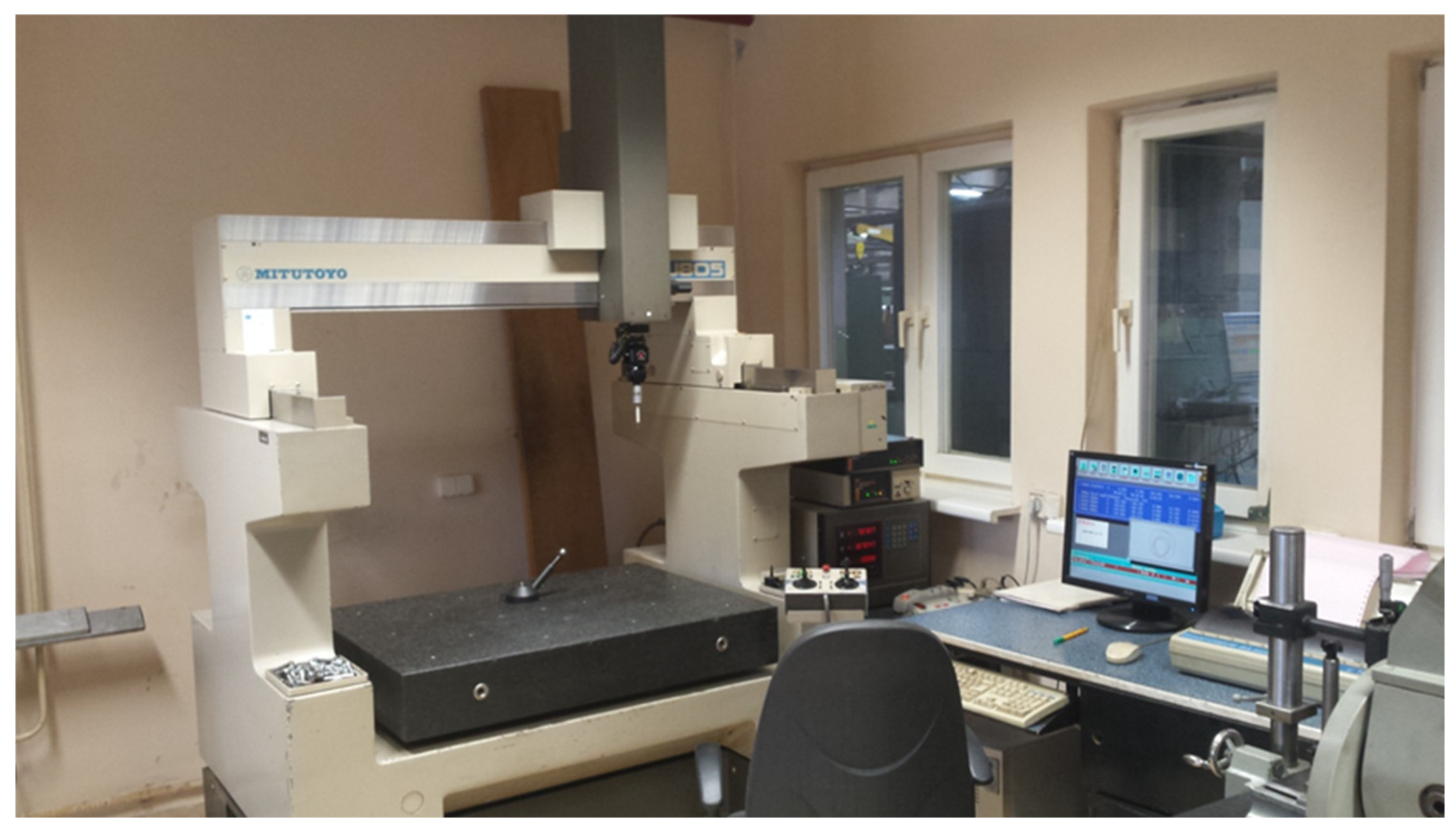
The third measurement was conducted using the manual measuring machine MITUYOYO FJ-805 (Nakatsugawa, Japan)—
Figure 2.
This is a bridge-type machine. Its mode of operation requires the involvement of an operator who moves the machine using a control panel. The direction of the joystick levers’ displacement corresponds to the direction of the machine’s support movement. Two joysticks are used for control—one for moving on the X and Y axes, the other in the direction of the Z-axis [
20]. This machine is equipped with a RENISHAW PH 10 M (Gloucestershire, UK) measuring head and a PT7M measuring probe (Gloucestershire, UK). The probe type is discrete. The measuring element is a ruby ball with a diameter of 3 mm. The axial inaccuracy of the machine’s indication is U95 = (4 + 0.5 L/100) µm, the value L is the measured length expressed in millimeters, and 0.5 L is half of this value. The Geopak-3 software, version 5.34 (PL), is used to operate the device.
Measurement with a manual machine is time-consuming and requires the participation of moderately skilled personnel. Approaching the measurement points is performed manually, with the operator deciding the point of contact between the probe and the element. The movement to the respective measurement points of the element occurs at a low speed. The advantage of this machine is its design. Air bearings do not cause wear on the machine’s moving parts. The measuring head used in it is a precise device, and the transmission of the signal to the machine’s controllers occurs automatically upon the probe’s contact with the surface being processed.
In order to standardize the results, the plate was initially based. A grid was also applied to facilitate the approach to selected points during measurements with the arm. The approach in the manual machine was based on the display of the measuring probe position.
The data obtained using the CMM machine are subject to a small measurement error; hence, the measurement using this machine was chosen as the reference. By comparing the time needed to conduct the study with the obtained result, a comparison of the achieved examination accuracy to the time required for its execution was made for the three evaluated methods. As the final result of the study time, we consider the time of preparing the measurement station, including writing a program for the CMM machine, and the time needed to collect the designated number of points from the studied surface. The least squares method was used to determine the parameters describing the plane based on the data from the obtained point cloud.
The article presents examples of tests in real conditions that we often encounter during repairs and maintenance of industrial equipment. Results for industrial conditions were achieved, which was crucial for this study, and an anomaly was indicated for the error detected by the measuring arm.
Figure 3 illustrates the process of surface flatness testing, organized in a hierarchical and logical manner. It begins with problem analysis, including the definition of flatness and its significance in construction. Next, the appropriate measurement method is selected, along with the consideration of using contact devices such as automatic machines, semi-automatic machines, or a measuring arm.
The following step involves selecting the measuring device and analyzing measurement technologies, as well as determining the number of control points. After conducting measurements using the chosen tool, the data are processed to determine flatness and the study time. Finally, the results are presented, and the process concludes with planning further research. The diagram demonstrates a methodical and systematic approach in eight steps to analyzing surface parameters.
In order to standardize the results obtained, each measurement began with the description of the coordinate system. This is a basic procedure that starts the measurement using coordinate measuring machines. It allows for the unambiguous determination of the position of an element in the working space of the machine, by performing measurements that take away all its degrees [
21].
To determine the position of an element in 3D space, three elements were used: a plane and two lines. The plane describes the position of the measurement base of the object in 3D space and removes three degrees of freedom from it. The first of the collected lines sets the X-axis, removing another two degrees of freedom. The last stage is the adoption of the starting point of the coordinate system of the examined element. We create it from the intersection of both measured lines. In this way, we take away the last degree of freedom.
The novelty of the study is based on the analysis of the possibility of replacing precise devices with less accurate ones by determining/examining at what number of measurement points such an approach is feasible. The application of an analytical method, typically used for point cloud analysis collected via scanners, contributes to measurements gathered using contact methods.
The aim is to evaluate in which applications fast and less precise devices can be sufficient, which is of great importance in the industry.
If a mobile device is used to measure in a hard-to-reach location, can we approximate the results obtained with stationary automatic and manual machines?
How does increasing the number of collected measurement points affect the measurement result, and how does it impact the time required to conduct the measurement?
3. Results and Discussions
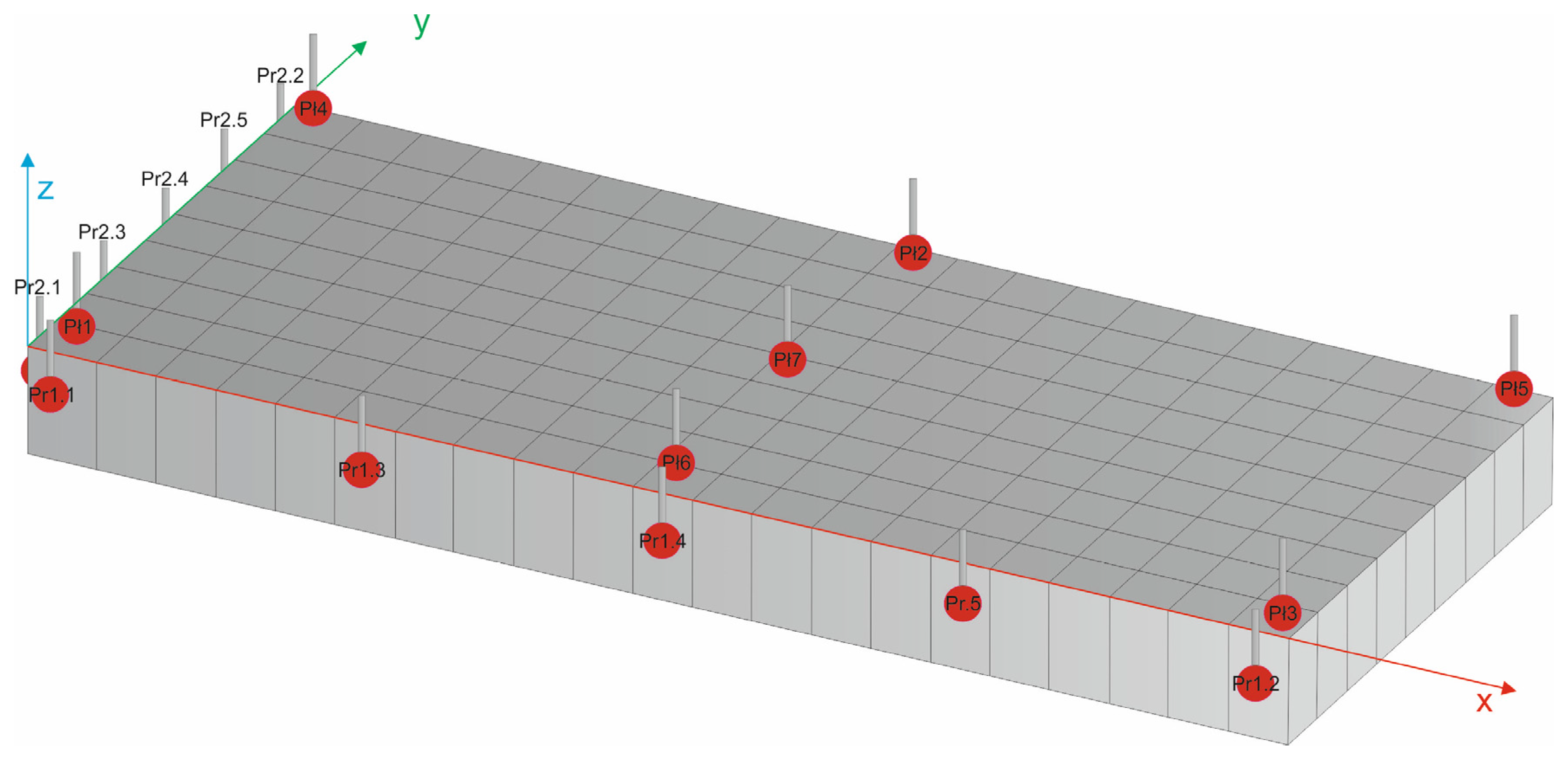
To unambiguously and mathematically determine the position of the studied plane in space, it is necessary to collect a specific number of points. For a plane, three points are needed, while for a line, two are needed. To increase the accuracy of the measurement, a larger number of points were collected. Faro’s training materials recommend collecting seven points for a plane and five points for a line [
22]. The distribution of points collected during the examination of the element is shown in the figure below (
Figure 4).
In order to conduct a comparison of the three selected measuring devices, a measurement of the surface of the element was performed at regularly spaced points. To increase the accuracy of the obtained results, 189 evenly distributed measuring points were collected from the tested surface for each of the examined methods.
Since the parameters of the measuring probes, the diameters of their balls, and especially the length are important factors affecting the accuracy of the measurement, a system with the same parameters was used for all studies [
19].
Automatic measuring machine. Both automatic and manual measuring machines are equipped with contact, trigger probe heads. These are heads commonly used in coordinate-measuring machines. Thanks to their high precision and sensitivity of the probes, as well as the use of modern algorithms for correcting the radius of the measuring tip, they demonstrate high reliability of the positioning of the obtained results in the measuring space [
23].
Preparing an automatic measuring machine requires not only startup and calibration but also writing a measurement program. Due to the weight of the part and the low pressure of the measuring probe, as well as the automatic operation that eliminates the accidental displacement of the element, there is no need to mount it. The measurement program required determining the position of the examined element in the measuring space of the device each time. After completing the measurement, an automatic file with the obtained measurement data was created—
Figure 5a.
Characteristic parameters:
Time needed to prepare the device: 4 min;
Time to write the measurement program: 16 min;
Measurement time of the plate: 12 min;
Total research time amounted to 32 min.
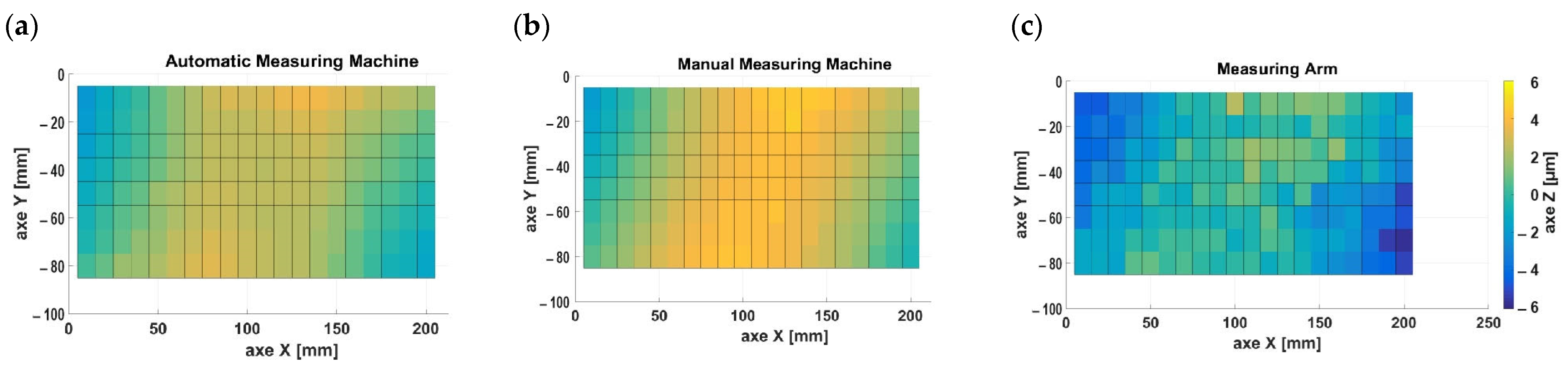
The measurement data presented in
Figure 5a indicate the bulging of the central part of the tested sample along the X-axis. Furthermore, there is visible twisting of the transverse section of the tested element. The surface of the chart is gently deformed and is contained between the Z-axis values of −20 µm and 30 µm.
Manual measuring machine. After starting the manual measuring machine and conducting the calibration of the measuring probe, a coordinate system was described on the part mounted on the machine. The next step was to perform four measurements at designated points on the surface of the element. An auxiliary grid applied to the plane was used to determine the examined point on the surface of the plate. After conducting the study, the obtained results were saved as a file with data containing three coordinates of the measured points—
Figure 5b.
Characteristic parameters:
Time needed to prepare the device: 6 min;
Measurement time of the plate: 13.5 min;
Total research time amounted to 19.5 min.
The values plotted in
Figure 5b indicate bulging and twisting of the tested sample. The mapped surface is more gentle and falls within the range for the
Z-axis from −20 µm to 40 µm.
Measuring arm. Measuring arms are characterized as portable devices, which is why they are equipped with additional battery power built into the base. The counterweight system used in the construction of the device allows for easy maneuvering with the device, including performing measurements with one hand [
13,
24].
Unlike measuring machines equipped with impulse measuring heads, the arm has a rigid head. Performing a measurement in this case requires the operator to exercise carefulness and skill during the testing process [
12].
Setting up the measuring arm for operation requires mounting it on a measuring plate and calibrating the measuring probe. Due to the rigid measuring probe, it is necessary to securely mount the element onto the measuring plate. The next step involves defining the coordinate system on the element being tested. In the measurements, an auxiliary grid was also used to determine the position of the point being examined. The results, in the form of XYZ coordinates in
Figure 5c, were exported as text files.
Characteristic parameters:
Assembly and disassembly of the measuring arm: 6 min;
Time required to prepare the measurement setup: 6 min;
Measurement time of the plate: 7 min;
Total research time amounted to 19 min.
The compiled results in
Figure 5c show significant differences in the
Z-axis between adjacent points. There are clear shape errors of the investigated plate visible. Values for the
Z-axis range from 0.00 µm to 60 µm. The characteristic parameters for the three measurement methods are shown in
Table 1.
Measurements of manual and automatic machines largely overlap both in shape and in error values. The chart obtained from the results of the measuring arm shows smaller values for the Z-axis as well as significant variation for adjacent points.
To determine the flatness deviation in coordinate measuring machines (CMMs), we use the least squares method of deviations. In this method, we determine a reference plane from the collected points, and then we define the distances between it and the individual measurement points. This distance is the deviation for the partial area of the tested surface. Points located above the surface are called positive locations, and those below are called negative locations. The surface flatness error is taken as the sum of the absolute values of the positive and negative locations [
25].
To determine the average plane from an n-element set of real points, it is necessary to establish the formula defining this plane. Here, we can use the formula for the plane given below (1):
In the least squares method, defining the plane requires calculating the parameters
a,
b, and
c. To obtain them, it is necessary to perform calculations of three equations, which in matrix form are expressed by Formula (2) given below:
Through this, we obtain an equation with which we can describe the plane. The next step is to calculate the distance of all points from the plane described by the equation, that is, the location of each point, constituting the partial flatness deviation of the surface under examination
di. We use Formula (3):
From the obtained partial flatness deviations, we determine the maximum and minimum value, and the sum between their absolute values defines the flatness error (
f) of the actual element in accordance with Formula (4):
The value
f (
Table 2) is thus a flatness parameter defined by the distance of the extreme points (minimum and maximum) from the reference surface.
The analysis of the accuracy and time required for measuring flatness deviations depends on several factors. The key factors include the number of measurement points, the repeatability of results, and the characteristics of individual measurement methods, such as the coordinate measuring machine (CMM), a manual machine, and a measuring arm. The choice of the appropriate method and the determination of the optimal number of measurement points have a significant impact on the reliability of results and the efficiency of the measurement process. The following section discusses how these elements influence the differences between the methods.
CMM (coordinate measuring machine): The most accurate method (flatness error f = 61.9 µm) with the highest measurement repeatability. However, a disadvantage is the long measurement time as the number of points increases (e.g., 60 points require 23 min). This method allows for process automation and only requires basic operator training.
Manual Machine: Good accuracy (flatness error f = 63.6 µm), but weaker measurement repeatability. The measurement time is shorter compared to the CMM machine but requires a skilled operator. At 100 points, it achieves a similar accuracy to the CMM within the range of 60–65 µm.
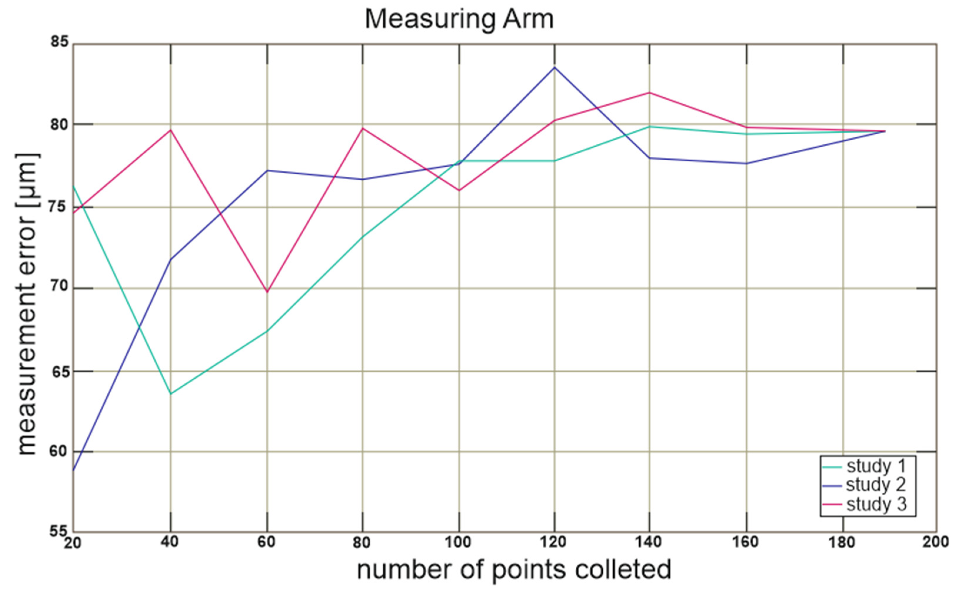
Measuring Arm: The least accurate method (flatness error f = 79.7 µm) with greater variability in results for a small number of measurement points. At 130 points, it achieves an acceptable repeatability range (77.5–82.5 µm). It is a fast method in practical use but demands physical effort and operator training.
In summary, the difference in results between the most precise method (CMM) and the least precise method (measuring arm) is 17.8 µm. The value of 17.8 µm is the difference between the “Obtained Flatness Error f, mm” for the measuring arm (79.7 µm) and the automatic measuring machine (61.9 µm) from
Table 2. The results show that the greater the number of measurement points, the closer the results become.
For devices with lower accuracy, systematic collection of a greater number of measurement points positively impacts the results, reduces the dispersion of the obtained values, and brings the results obtained using different methods closer together. Consequently, a properly planned collection of measurement points allows the use of a mobile device to achieve approximate results. However, achieving more accurate results requires the use of stationary machines.
Because in the case of measuring shape deviations of elements, the commonly used strategy of even distribution and the quantity of collected points do not always yield the desired results, an analysis of the obtained results for random and systematic sampling was performed [
21].
In two devices (manual machine and automatic machine), the same measuring tip was used, while in the measuring arm, a ball of the same diameter was used.
3.1. Random Distribution of Measurement Points
The next stage of the research involved obtaining results (
Figure 6,
Figure 7 and
Figure 8) based on a smaller number of measurement points.
In the first part of the study 20, 40, 60, 80, 100, 120, 140, and 160 measurement points were selected randomly from the obtained results. In the study, “random selection” refers to the random selection of measurement points on the surface, without favoring specific areas. These points were chosen using appropriate random sampling techniques with a uniform distribution to avoid introducing biases stemming from prior knowledge of the surface structure. Such a methodology allows for the collection of representative data, enabling an objective assessment of flatness. Due to the expected lack of repeatability of the flatness result obtained in this manner, each test was performed three times. This means that each time, points were selected from different data sets, and the measurement was also performed three times.
Random selection of measurement points on the deformed surface of the plate shows underestimated flatness error values for 20–40 points, which is evident in
Figure 6. For measurements above 80 points, the change in the obtained results is minimal and is less than 10 µm.
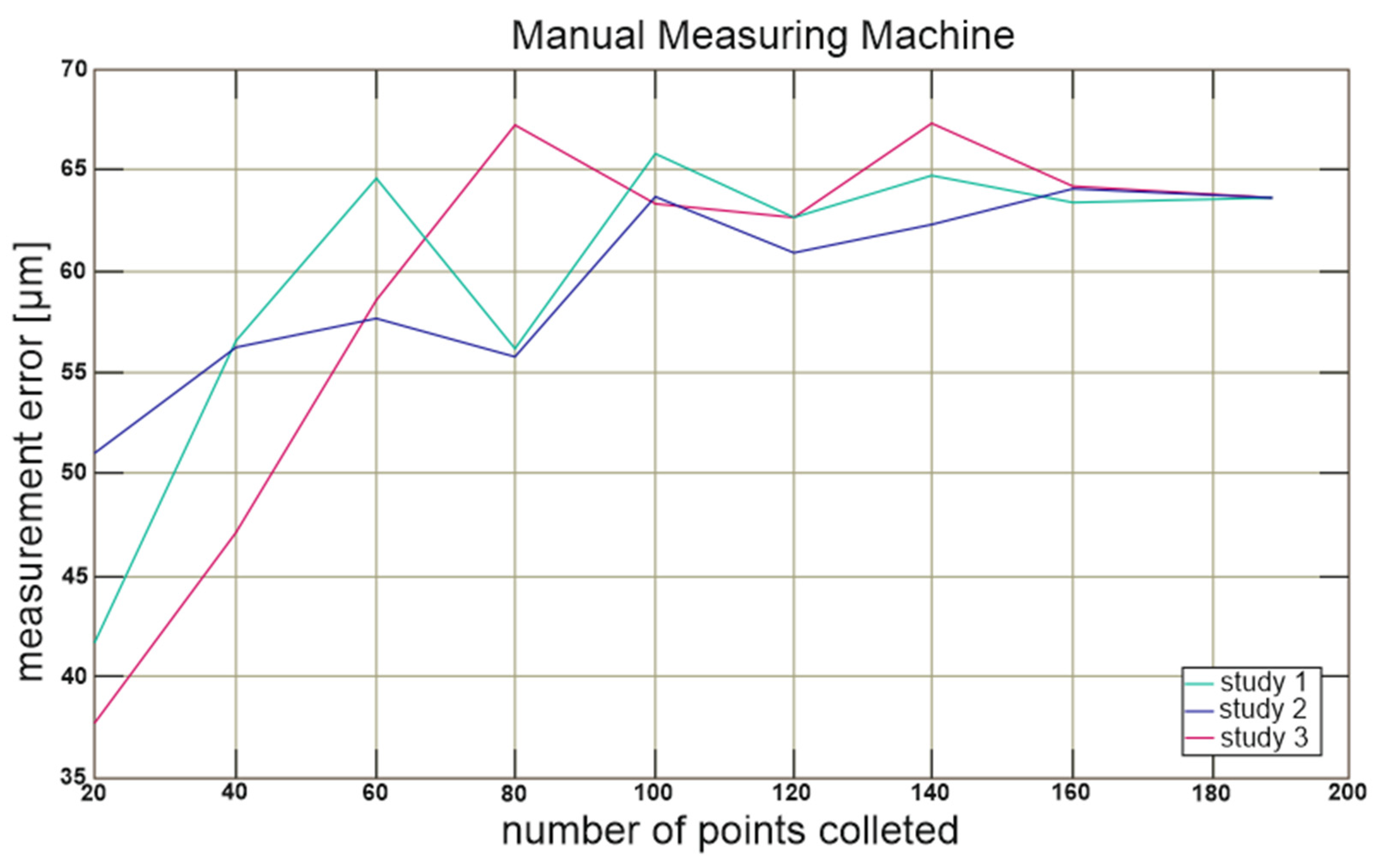
In the case of results from a manual machine,
Figure 7 presents the recorded difference in the obtained results even for 80 points. When measuring above 100 points, the discrepancy of the obtained results falls below 10 µm and is close to the values obtained from an automatic machine.
Measurements obtained in the range up to 100 points show both a large diversity and a deviation from the average value of the total number of measurements, which can be observed in
Figure 8. For a greater number of measurement points, the deviation also stabilizes within an error margin of ±10 µm; however, the average value is about 10 µm higher.
Based on the obtained results, a summary was prepared of the time needed to conduct the study and the observed deviation, as the average result from the three quantities of collected points obtained in the study—
Figure 9.
The time it takes to perform measurements for an automatic machine is significantly longer than for the other two devices. This especially pertains to the time needed to prepare the device before starting the measurements. The measurements can be started fastest on a manual machine; however, in the case of measuring a larger number of points (according to the chart, about 180 points), the total measurement time for an articulating measuring arm is shorter.
The flatness error obtained from the articulating measuring arm is larger than in the manual machine, but the error range for the obtained results is smaller. In the case of the automatic machine, the measurement results for both the average value of the error and the error range are the smallest.
3.2. Systematic Distribution of Measurement Points
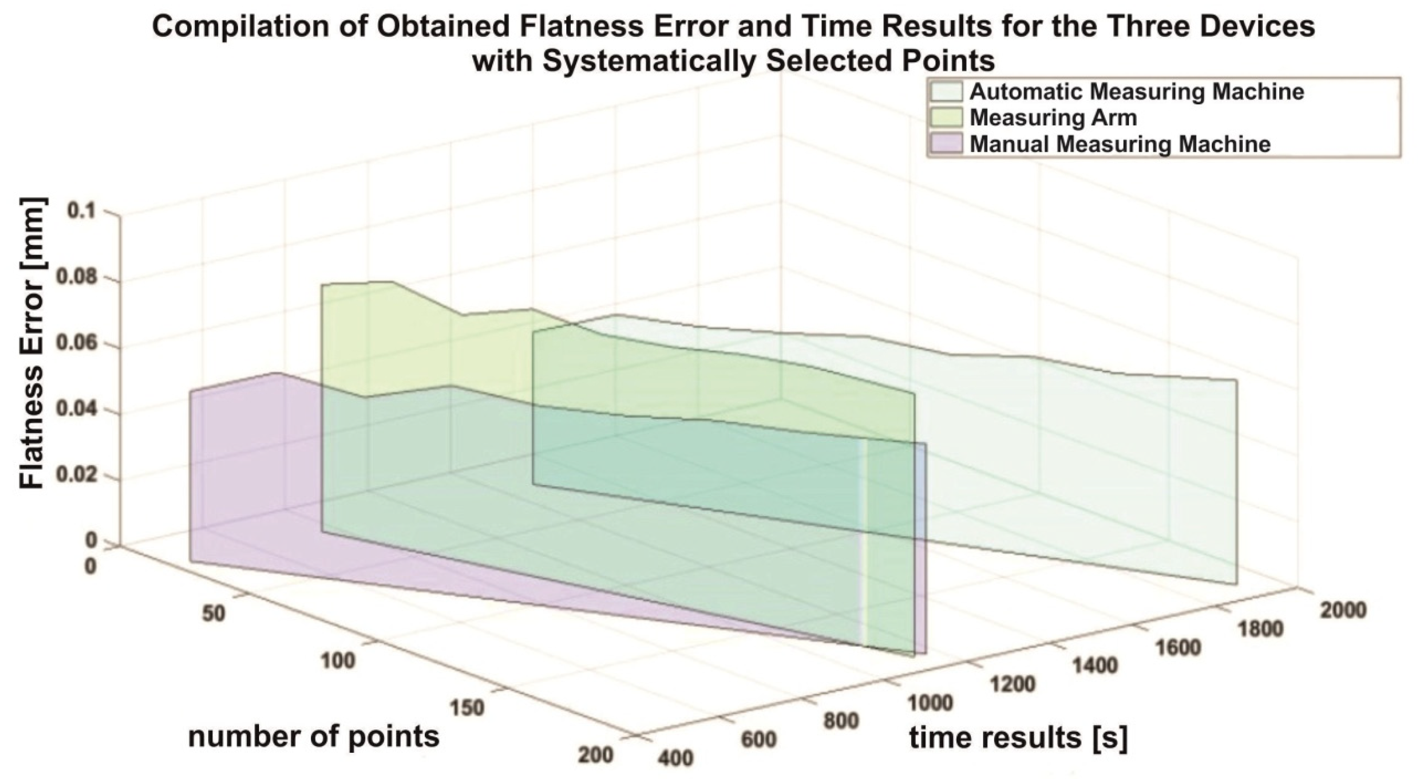
In contrast to the randomly selected points, this study used specific measurement points of the examined surface. The assumption was to achieve the same number of point sets as with the random method. A selection of evenly distributed points from a matrix containing data on all 189 points collected during the study was used. The obtained results are presented in the summary below—
Figure 10.
Figure 10 confirms the results presented in
Figure 9. Preparing an automatic machine takes more time; however, the results obtained with its help have the smallest flatness error. We can start the results fastest on a manual machine, but with a large number of points, the total measurement time for the measuring arm will be less. The measuring arm requires more time to prepare before starting measurements, but the measurement is shorter, so with a large number of collected points, the measurement will take less time. The flatness error range of the results obtained for both devices is at a similar level; however, the average value of the flatness error for the arm is greater.
Plane measurement accuracy—the central point of our article is the analysis of the accuracy of plane flatness measurements made using different methods: CNC machine, manual machine and measuring arm. This study sheds light on the unique properties of the CNC machine, which is characterized by the smallest flatness error with a value of (f) = 61.9 µm, emphasizing its superiority in terms of accuracy over other methods.
The inaccuracies of the machine readings along with their resolution are in
Table 3. Each machine has the same elementary unit, which is 1 µm (micrometer). Measurement repeatability—the second key area of our interest is the analysis of the repeatability of results obtained using the above-mentioned techniques. We have shown that the CNC machine shows the highest repeatability, which is important when taking into account the efficiency of measurements in various production and repair scenarios.
Repair and production application—the focus is also on the discussion of the practical application of different measurement methods in the context of individual, small-scale production and repair work of large power machines. We indicate how the choice of measurement method affects the efficiency and time consumption of the process, as well as the possible benefits of measurement automation.
Table 4 and
Table 5 present both the advantages (e.g., the possibility of replacing precise devices under certain conditions) and limitations (e.g., low repeatability of results in the case of a measuring arm for a small number of points) of the tested methods, with reference to our own concept presented in this article.
Application scenarios:
- (1)
Manual method.
Restoration of monuments and conservation work: Where precision and gentle handling are essential and modern methods may be too invasive for delicate materials.
Small craft workshops: In the case of low-volume production, where the costs of introducing automated measuring systems are not economically justified.
Education and training: As a basic method for teaching the foundations of measurement techniques, allowing the understanding of basic principles without the need for advanced technology.
- (2)
Semi-automatic method.
Small- and medium-sized manufacturing companies: Where greater efficiency is required than with manual methods, but full automation is not justified due to production variability or costs.
Prototyping and testing: Where rapid adaptation to different types of measurements is necessary, and at the same time, greater precision is needed than with fully manual methods.
Quality control in series production: As a compromise between speed and cost, allowing for quick switching between different product batches.
- (3)
Fully automatic method.
High-quality mass production: Where consistency and speed of measurement are key to maintaining quality standards at high production volumes.
Automotive and aerospace: In areas where very high precision and repeatability of measurements are critical to safety and efficiency.
Advanced technology research and development: Where innovative designs require precise, repeatable measurements in complex conditions or on small, delicate components.
The objective was to identify the differences between these three devices and determine to what extent a device with a higher measurement error can replace a more precise device. Increasing the number of measurement points makes the results obtained on these devices more similar. The use of random distribution of measurement points aimed to determine the impact of uneven point distribution on the final result. This work demonstrates that in some industries, where tolerances do not need to be too stringent, less precise instruments may prove to be sufficient. In such cases, these instruments allow for cost, time, and resource reduction required for measurements. The authors explored whether less precise devices could be accepted under industrial conditions. It is also worth noting that many companies do not practically analyze the risk of using less accurate devices, which makes this research valuable and a significant contribution to the field of measurements for industrial applications. The measurement method can be applied to objects where heavy, large measurement machines cannot be transported, as they often require specific environmental conditions to perform measurements, and disassembly of the element is either impossible or uneconomical. In future work, the following is planned:
Use the developed methods to measure spatial surfaces such as cylinders.
Develop new methods for analyzing several cooperating planes and their relative positions based on collected contact points.
Investigate the influence of environmental conditions (e.g., temperature, humidity) on measurement accuracy.
Extend the analysis to other flatness measurement techniques and use other devices.
Develop methods to increase the accuracy of fast measurements using devices with larger basic errors, such as a measuring arm, so that they can more effectively replace precision machines.


 ,
, 


