Article

Mechanical Damage Characteristics and Energy Evolution Laws of Primary Coal–Rock Combinations with Different Coal–Rock Ratios

1
Emergency Science Research Academy, Chinese Institute of Coal Science, Beijing 100013, China
2
Joint National-Local Engineering Research Centre for Safe and Precise Coal Mining, Anhui University of Science and Technology, Huainan 232002, China
3
China Coal Research Institute, Beijing 100013, China
4
School of Emergency Management and Safety Engineering, China University of Mining & Technology (Beijing), Beijing 100083, China
*
Author to whom correspondence should be addressed.
Appl. Sci. 2025, 15(6), 3091; https://doi.org/10.3390/app15063091
Submission received: 23 November 2024 / Revised: 3 March 2025 / Accepted: 11 March 2025 / Published: 12 March 2025

Abstract

:
To investigate the mechanical damage characteristics and energy evolution laws of primary coal–rock combinations with different coal–rock ratios, uniaxial compression tests were conducted. Combined with acoustic emission monitoring results, a comparative analysis was performed on the yield strength, elastic modulus, acoustic emission signal characteristics, failure characteristics, and energy accumulation–dissipation characteristics of five different coal–rock ratio specimens. The study reveals the following: (1) Defect structures and dimensions of coal bodies influence the strength of specimens, with the peak stress and elastic modulus of specimens showing a decreasing trend with an increasing coal–rock ratio. (2) The transitional zone of primary coal–rock composite exhibits distinct interface effects on coal and rock components. Coal-derived stresses manifest as horizontal tensile stresses, promoting deformation at the interface between coal and rock, whereas rock-derived stresses at the interface manifest as horizontal compressive stresses, restricting deformation at the coal–rock interface. Moreover, positions closer to the interface experience stronger limitations due to the interface effects. (3) Coal–rock interface cracks are more developed in the primary coal–rock composite, with multipoint cracking occurring at the interface during failure, and a feedback mechanism between coal and rock failure exacerbates the damage and dynamic manifestation intensity of coal bodies. (4) The acoustic emission signals from single-rock samples indicate shear failure of the specimens. Conversely, the acoustic emission signals from single-coal samples and combinations suggest that tensile failure is the primary destabilizing factor. Moreover, with an increase in the proportion of coal, specimens transition from tensile failure to tensile–shear composite failure.

1. Introduction

Coal is the mainstay of China’s energy consumption structure and plays a crucial role as one of the primary foundational energy sources for the country’s economic development [1,2,3,4,5]. With shallow coal resources gradually depleting, coal mining is gradually transitioning to deeper levels, where the environmental stress becomes complex and variable, leading to frequent dynamic hazards, such as rock bursts and gas outbursts. The overall instability and failure of the “coal–rock” combination structure under mining influence are among the primary causes of dynamic hazards [6,7,8,9,10,11]. Primary coal–rock combination specimens, taken from natural strata, represent the fundamental units of the strata structure and better characterize the actual strata morphology [12,13,14]. Therefore, it is necessary to conduct uniaxial compression experiments on primary coal–rock combinations to study the mechanical damage characteristics and energy evolution laws of different coal–rock ratios, aiming to provide a research basis for the prevention and control of dynamic hazards in deep coal mining.
Scholars have conducted extensive research on coal–rock combination specimens, yielding numerous achievements. Firstly, in terms of mechanical properties and influencing factors, Peng et al. [15] conducted uniaxial compression experiments and analyzed the strength, failure mode, and crack distribution of coal–rock specimens under different bedding dip angles using CT scanning technology. Guo et al. [16] comparatively studied the mechanical characteristics and acoustic emission response patterns of five different height-to-diameter ratio coal samples under uniaxial compression conditions, concluding that the uniaxial compressive strength of the specimens decrease with the increase in the height-to-diameter ratio, and proposed an empirical equation for calculating compressive strength. Zhao et al. [17] conducted uniaxial compression tests on coal–rock composite specimens consisting of six different lithologies, coupled with an acoustic emission system, to investigate the evolutionary laws of mechanical properties of the samples. Lei et al. [18] used five groups of coal samples with different heights but the same diameter as research objects and conducted Brazilian splitting tests with synchronous acoustic emission monitoring systems, exploring the mechanical properties, fracture patterns, and acoustic emission response characteristics of coal samples with different height-to-diameter ratios. Nazarova LA et al. [19], through conducting axial compression tests on coal, used the empirical relationship between elastic wave velocity and stress as a starting point to analyze the relationship between P-wave velocity, axial stress, and confining pressure.
The energy transfer and damage accumulation mechanisms during failure have been systematically investigated. Chen et al. [20] conducted axial compression experiments on coal–rock combinations with different coal–rock ratios and combination modes, analyzed the mechanical properties of the combinations, established a combination interaction model, and revealed the instability failure mechanism and energy transfer mechanism of the combinations. Fan et al. [21] conducted uniaxial compression tests on coal–rock combinations and clarified the strength, elastic modulus, failure characteristics, and energy accumulation evolution laws of combinations under different coal thickness conditions, and proposed a method for determining the impact tendency. Zhang et al. [22], based on the development of cracks and energy evolution, combined experimental and simulation methods to explore the evolution laws of the quantity, length, and macroscopic area of cracks during the failure process of different coal–rock combinations, and found that the damage stress threshold of the specimens increases with the increase in the coal–rock ratio. Tahmasebinia et al. [23] proposed a damage model for the thermodynamic continuity constitutive model of the coal–rock interface, and conducted a systematic study on the energy conversion laws between the coal body and rock.
The above-mentioned research mainly focuses on the strength, energy evolution, progressive failure, and acoustic emission characteristics of different lithologies and different height-to-diameter ratio composite specimens. The research objects are mostly single-coal samples, single-rock samples, or artificially made coal–rock composite specimens with smooth interfaces. Coal, as a structurally complex porous medium, contains a large number of original pore and fracture structures. Compared with artificially made coal–rock composite specimens, primary coal–rock combinations retain the complex defect structures inside the coal body, which can better reflect the real coal seam structure. Previous studies have shown that coal thickness has a significant impact on the mechanical properties of combinations. Therefore, it is of great significance to conduct research on the mechanical damage characteristics and energy evolution laws of primary coal–rock combinations with different coal–rock ratios.

2. Specimen Preparation and Testing Process

2.1. Specimen Preparation

The experimental samples in this study were collected from Baode Coal Mine in Hedong Coalfield. The coal seam contains numerous layers of gangue, with stable occurrence, and the lithology is mudstone, which exhibits high strength and low permeability. Samples were taken from the working face of the No. 8 coal seam, which shares similar characteristics with the No. 11 coal seam in terms of occurrence conditions and coal–rock parameters. Due to the susceptibility of interface damage in composite specimens, to ensure the integrity of the samples, large coal–rock composite specimens were sawed into smaller pieces on-site, then processed through steps including wire cutting, trimming, and grinding to obtain samples suitable for experimentation. Sample processing followed the testing methods recommended by the International Society for Rock Mechanics, with the flatness and perpendicularity of the sample ends and sides after grinding both being less than 0.02 mm.
Samples of dimensions d50 mm × h100 mm were prepared, including single-coal samples; single-rock samples; and primary coal–rock combinations with coal–rock ratios of 3:7, 5:5, and 9:1 (referred to as primary coal–rock combinations in this study). Additionally, artificial coal–rock composite specimens were created by naturally joining d50 mm × h50 mm coal and rock samples to form d50 mm × h100 mm composite bodies (referred to as artificial coal–rock composite specimens in this study). Figure 1 illustrates a schematic diagram of the specimens.

2.2. Testing Process

Rock mechanics experiments are fundamental methods for determining the basic mechanical properties of rock materials and are important means of revealing the strength and deformation characteristics of rock-like materials [1]. In order to obtain the basic mechanical parameters of coal–rock masses, this section employs a uniaxial loading method to load coal samples, rock samples, primary coal–rock combinations, and artificial coal–rock combinations separately, with a loading rate of 100 N/s, until the samples are fractured and the loading is stopped. During the experiment, acoustic emission signals generated during the sample’s damage and fracture process are synchronously collected. Strain gauges are used to measure the axial and radial strains of the samples. For primary coal–rock combinations and artificial coal–rock combinations, the measured axial deformation value represents the sum of the axial deformations of the coal body and rock body, while the measured radial deformation value represents the radial deformation of the coal body proportion. See Table 1 for detailed sample information.
This study utilized the RLW-500G coal–rock triaxial testing system to conduct uniaxial loading tests on samples. The maximum axial loading pressure of the equipment is 500 KN. The acoustic emission testing equipment used was the PCI-2 acoustic emission test analysis system manufactured by Physical Acoustics Corporation of the United States, with a sampling frequency of 5000 KHz and a threshold of 46 dB (Figure 2). Six groups of samples were prepared. Combined with the acoustic emission system, uniaxial compression tests on samples were conducted to reveal the deformation and failure characteristics, as well as the response laws, of coal–rock composite samples with different coal–rock ratios. This is aimed at providing a certain research basis for the prevention and control of dynamic disasters in deep coal mining. The samples (raw coal–C, rock–R, artificial coal–rock combination–CR, primary coal–rock combination–CSR) were set with five different coal–rock ratios, namely, 10:0, 0:10, 5:5, 3:7, and 9:1.

3. Results

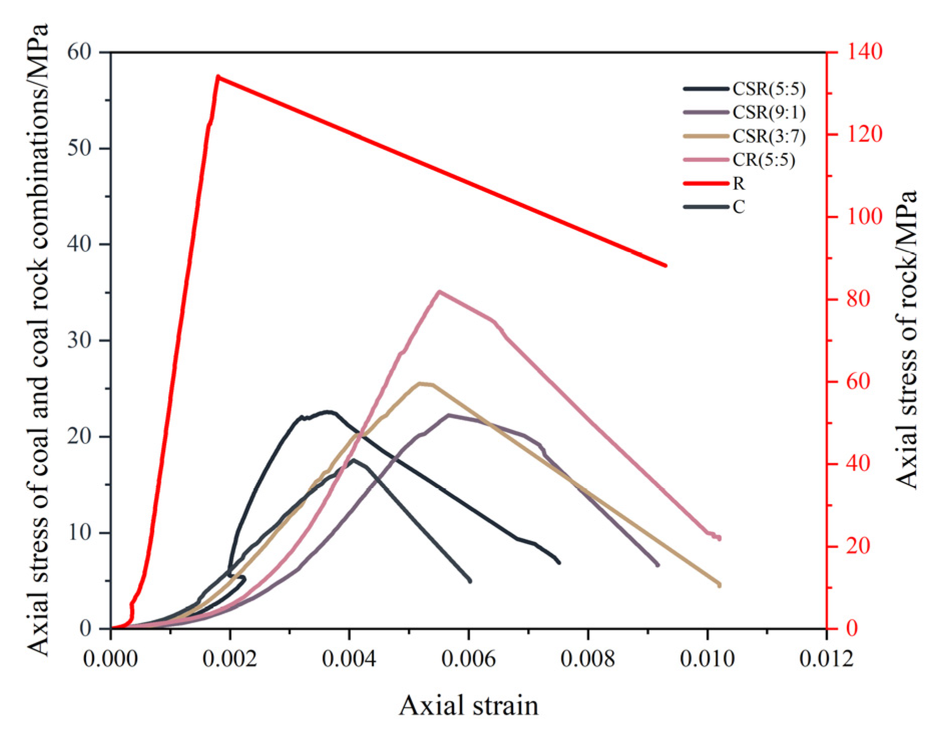
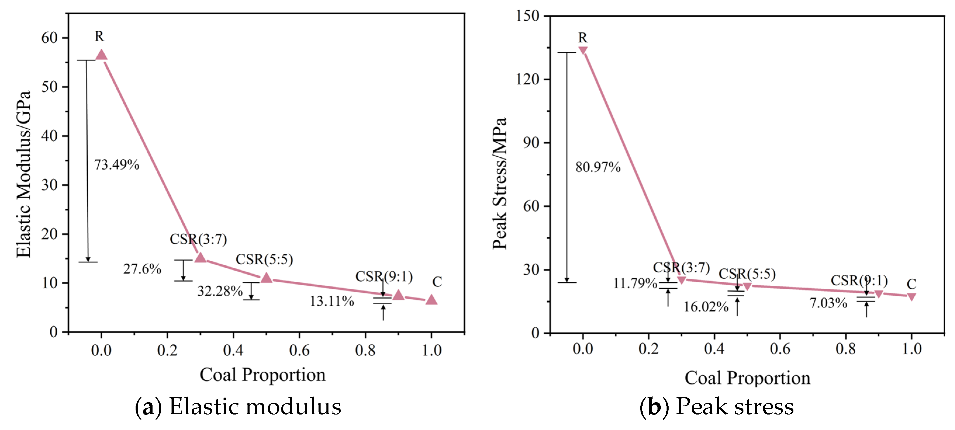
3.1. Deformation and Strength Characteristics

From the stress–strain curves (Figure 3), it can be observed that the damage and failure behavior of the six types of samples, C, CSR (9:1), CSR (5:5), CSR (3:7), R, and CR (5:5), under uniaxial compression are broadly similar. They all undergo compaction, elastic, yielding, and post-peak failure stages. As the axial stress gradually increases to the peak stress, the load-bearing capacity of the samples gradually diminishes, and the axial stress rapidly decreases.
Typically, either the secant or the tangent slope of the stress–strain curve near 50% of the peak strength is used. In this study, we adopt the tangent slope. For the detailed formula, please refer to Equation (6).
In this experiment, the peak stress of a single-rock sample is 134.18 MPa, with an elastic modulus of 56.31 GPa. When the coal–rock ratio is 3:7, the peak stress of the sample is 25.53 MPa, with an elastic modulus of 14.93 GPa. When the coal–rock ratio is 5:5, the peak stress is 22.52 MPa, with an elastic modulus of 10.81 GPa. When the coal–rock ratio is 9:1, the peak stress is 18.92 MPa, with an elastic modulus of 7.32 GPa. The peak stress of a single-coal sample is 17.59 MPa, with an elastic modulus of 6.36 GPa. Compared with the sample with a coal–rock ratio of 0:10, the uniaxial compression strength of the composite samples with coal–rock ratios of 3:7, 5:5, 9:1, and 10:0 decreased by 80.97%, 83.22%, 85.9%, and 86.89%, respectively, while the elastic modulus decreased by 73.49%, 80.8%, 87%, and 88.71%, respectively. Therefore, with the increase in coal–rock ratio, both the uniaxial compression strength and elastic modulus (E) of the composite samples show a decreasing trend (Figure 4).
The varying strengths of the samples indicate that the failure primarily occurs within the coal component. As the coal–rock ratio decreases, the overall strength and deformation resistance of the samples gradually increase. This phenomenon stems from coal being a unique type of rock characterized by numerous inherent defects, such as microcracks and micropores. These defects inherently influence the strength of coal. However, as the coal proportion diminishes within the coal–rock composite samples, the prevalence of defects decreases accordingly. Consequently, this leads to an enhancement in the composite coal–rock sample’s strength and deformation resistance capabilities.
Comparing the primary coal–rock composite CSR (5:5) with the artificial coal–rock composite CR (5:5), the peak stress of the artificial composite is 35.13 MPa with an elastic modulus of 11.9 GPa, both exceeding those of the primary coal–rock composite CSR (5:5), which measures 22.52 MPa for peak stress and 10.81 GPa for elastic modulus. This disparity arises from the presence of distinct coal–rock transition zones at the interface of the natural coal–rock composite, contrasting with the smooth interfaces of the artificial coal–rock composite. Due to differences in the Poisson’s ratio between coal and rock, these transition zones in the natural composite generate varying interfacial effects on different parts of the composite, restraining coal deformation and promoting rock deformation. Consequently, this alteration in deformation mechanisms leads to variations in the strength and elastic modulus of the composite.

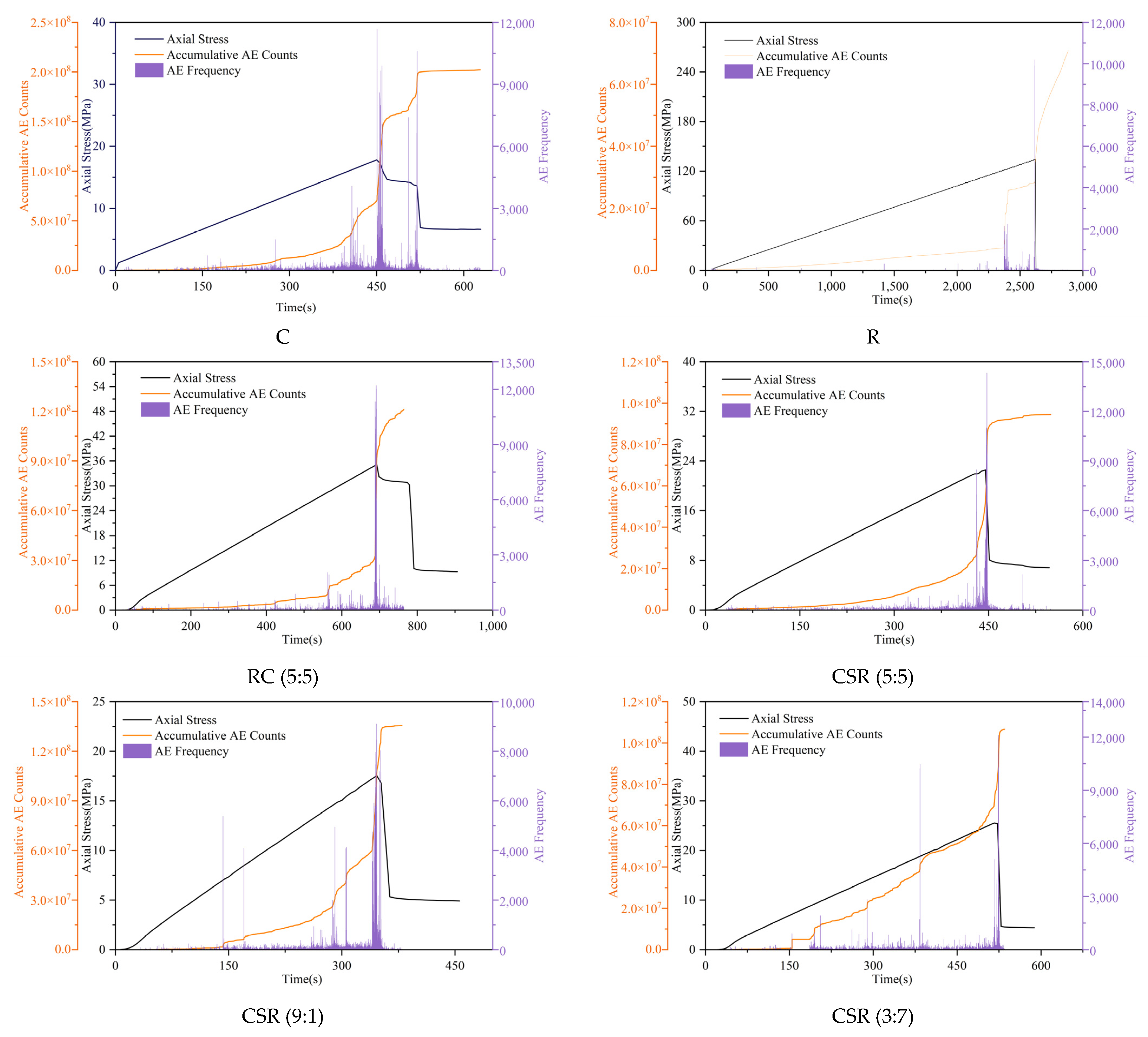
3.2. Damage Characteristics

Acoustic Emission (AE) refers to the transient elastic wave phenomenon generated by the rapid release of energy in a medium. It can be used to evaluate the rate of crack propagation and the process of damage development in specimens. AE monitoring was conducted during uniaxial compression of specimens, yielding characteristics of AE variation with stress in the form of a curve [3].
The relationship between axial stress, AE event frequency, and cumulative AE counts is illustrated in Figure 5. Different coal–rock ratio specimens exhibit similar AE characteristics, which can be divided into four stages. In the initial loading stage, both AE event frequency and cumulative AE counts are relatively low. This is attributed to the presence of inherent cracks and pore structures within the coal body, leading to compaction of the specimen. During this stage, inherent cracks within the coal body continuously close, and concurrently, with the decrease in coal content, the cumulative AE counts for samples C, CSR (9:1), CSR (5:5), CSR (3:7), and R are 17,698; 17,105; 14,703; 11,759; and 8821, respectively, accounting for 0.8%, 1.26%, 1.56%, 1.22%, and 1.24% of the total cumulative AE counts, respectively. This indicates that a higher coal–rock ratio corresponds to more initial microcracks within the coal sample, resulting in a greater number of AE signals released during compaction. As axial stress increases, the specimen enters the stage of elastic deformation, during which AE activity relatively intensifies, and cumulative AE counts exhibit an approximately linear growth trend. In this stage, initial microcracks within the coal sample are further compacted, and a small amount of cracking occurs. When the axial stress reaches around 75% of the peak strength of the specimen, the specimen gradually enters the yielding stage of progressive failure. During this stage, AE events become active, the AE count curve shows a “sudden change” fluctuation, AE counts become denser, several peaks appear, and cumulative AE counts almost vertically rise and reach their maximum near the peak stress. Numerous new cracks develop within the specimen, indicating the onset of macroscopic cracking and failure characteristics, accompanied by brittle sounds. After reaching the peak failure stage, axial stress rapidly decreases, causing the specimen to lose its bearing capacity. Cracks within the specimen gradually expand, forming macroscopic larger cracks, leading to continuous surface damage.
With an increase in the coal–rock ratio, the final cumulative AE counts of the specimens also increase continuously, and the AE characteristics of the specimens undergo corresponding changes. For specimens with relatively high coal content, such as C and CSR (9:1), multiple peaks in the AE event frequency occur near the peak stress, and cumulative AE counts show a stepwise increase. Overall, for specimens with coal–rock ratios of 0:10 (R), 3:7, 5:5, 9:1, and 10:0 (C), the cumulative AE counts are 7.09 × 10⁵, 1.07 × 10⁶, 1.31 × 10⁶, 1.35 × 10⁶, and 2.02 × 10⁶, respectively. Compared to the 0:10 (R) ratio, they increase by 50.92%, 84.77%, 90.41%, and 184.91%, respectively. This is because coal, as a special type of rock containing microcracks and micropores, generally has a much greater number of inherent cracks within its structure compared to rocks. The closure and sliding activity of internal cracks within coal are more frequent, leading to frequent AE activity. Therefore, with an increase in the coal component of the specimen, the number of AE count peaks increases, and cumulative AE counts also increase accordingly.
Comparing the time-varying patterns of AE counts between the primary coal–rock combination CSR (5:5) and the artificial coal–rock combination CR (5:5), the cumulative AE counts for the primary coal–rock combination and the artificial coal–rock combination are 1.31 × 10⁶ and 1.21 × 10⁶, respectively, with the former being 8.26% higher than the latter, indicating relatively active damage activity at the coal–rock interface of the primary coal–rock combination.

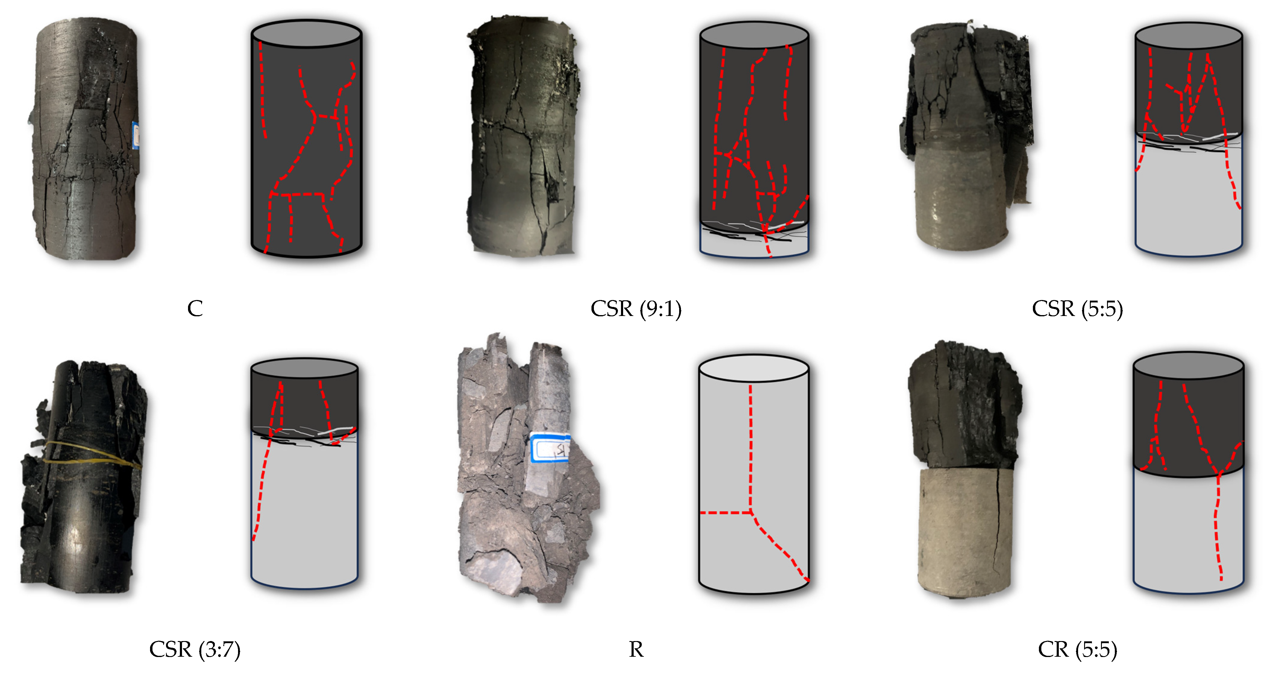
3.3. Failure Characteristics

As shown in Figure 6, under uniaxial loading conditions, the single-coal specimen (C) exhibits significant tensile failure, with evenly distributed cracks on the coal surface, a fractured zone at the top edge, and a relatively intact overall morphology. When the proportion of coal in the combination is 90% (CSR (9:1)), the number of cracks on the coal surface increases; some cracks extend from the coal part to the rock part through the interface; and the number of cracks in the coal component decreases with the generation of interface effects, with no overall failure in the rock part. When the proportion of rock in the combination is 50% (CSR (5:5)), shear failure occurs in the primary coal–rock composite specimen, with the main crack penetrating the entire specimen through the coal–rock interface, and multiple cracks appearing in the rock part at the interface; the artificial coal–rock composite specimen exhibits clear tensile failure characteristics in both the coal and rock parts. When the proportion of rock in the combination is 30% (CSR (3:7)), the main cracks are distributed between the coal and rock; the integrity of the specimen is poor; and both the coal and rock parts of the combination exhibit fractured zones, with tensile failure occurring in the rock part, forming a macroscopic fracture zone. A single-rock specimen (R) exhibits only two main cracks with a large inclination angle, and the specimen undergoes overall shear failure.
Comparing the failure characteristics of the primary coal–rock combination CSR (5:5) with the artificial coal–rock combination CR (5:5), it is found that the primary coal–rock combination has a larger number of cracks extending into the rock part, with the main crack penetrating the coal–rock interface and extending multiple cracks at the interface, resulting in a more complex failure morphology. The artificial coal–rock combination exhibits obvious tensile failure characteristics, with the main crack in the coal part extending into the rock, but not penetrating the combination. Furthermore, the primary coal–rock combination experiences more severe damage. This is because the interface effect at the coal–rock interface of the primary coal–rock combination causes irregular stress concentration due to the unevenness and interlocking of the interface, leading to more developed coal–rock fractures at the interface, resulting in multiple-point initiation of failure at the interface of the primary coal–rock combination. When cracks in the rock part begin to extend and propagate, the failure of the coal induces the failure of the rock, releasing a large amount of energy into the coal, exacerbating the damage and failure intensity of the coal, thus forming a feedback mechanism of failure between the coal and the rock.
In summary, the failure modes of the specimens can be divided into two types: tensile failure and shear failure. Tensile failure is characterized by nearly vertical main crack morphology penetrating the entire specimen axis, with parallel tensile stresses densely distributed along the coal specimen’s side surface. This is because of the presence of inherent cracks and pore structures in the coal specimen, causing stress concentration near these defects, leading to tensile failure when the stress reaches the tensile strength of the material horizontally. On the other hand, shear failure is characterized by typical “X”-shaped shear failure surfaces formed by the main cracks, which occurs when the coal specimen undergoes shear displacement due to the failure of the coal, and the cohesive force of the rock part cannot prevent the overall displacement of the specimen, resulting in shear failure along the coal fractures, eventually leading to shear failure.
The following is an inversion of the sample’s failure characteristics based on the characteristics of the acoustic emission response. As mentioned earlier, when a uniaxial compressed specimen undergoes damage and instability, its failure modes mainly include tension failure and shear failure. Different failure modes exhibit different acoustic emission signal characteristics, thus allowing for the inversion of the failure mode of the loaded specimen through acoustic emission signals. Commonly used methods for acoustic emission inversion require parameters such as rise time, amplitude, ringing count, and duration [4]. RA represents the ratio of rise time to amplitude, while AF represents the ratio of ringing count to duration. RA and AF values constitute important parameters for crack model recognition. Tension failure generally exhibits high AF values and low RA values, while shear failure exhibits the opposite characteristics [24]. Therefore, through the characteristics of the acoustic emission signals, it is relatively simple to discriminate the failure mechanism of the specimen under stress loading, as shown in Figure 7.
Among them, K is the ratio of the maximum AF value to the maximum RA value, and the value of K depends on the properties of the material. The K value for the analysis of the failure mode of the specimen is determined based on the reference of the maximum measured values of RA and AF in the acoustic emission signals during the experiment, which ranges from 1 to 4.
As shown in Figure 8, RA values mainly range from 0 to approximately 50 ms/v, while AF values mainly range from 0 to approximately 150 kHz, with the most data points near the origin. For a single-rock specimen, the proportion of RA values reaches 90.78%, showing low AF and high RA characteristics, indicating that during uniaxial compression, the main failure mechanism is the formation, development, and extension of shear cracks, corresponding to the macroscopic crack failure characteristics of the rock specimen described earlier, with two cracks appearing on the surface of the rock specimen exhibiting a large inclination angle, and the specimen undergoing shear failure overall. The acoustic emission signals of the single-coal specimen and the composite specimen mainly concentrate near the AF axis, showing clear high AF and low RA characteristics, indicating that tensile failure is the main factor leading to instability and failure. Moreover, as the proportion of coal increases, the proportion of RA values gradually increases, while the proportion of AF values decreases, indicating that shear cracks begin to form, develop, and extend inside the specimen, interconnecting with tensile cracks, eventually transitioning from tensile failure to tensile–shear composite failure.

3.4. Analysis of Energy Evolution Law

The essence of specimen deformation and failure lies in the development of microscopic cracks within the specimen under the action of external loads, progressing from disorder to order and eventually forming macroscopic cracks along a certain direction, leading to overall instability and failure of the specimen. From an energy perspective, this can be explained as the sudden release of energy. Therefore, in order to delve into the deformation and failure characteristics of specimens, it is necessary to study their energy conversion mechanisms [6].
The damage and failure of coal–rock mass represent a state instability phenomenon driven by energy. Investigating the energy variation patterns during the failure process of primary coal–rock combinations with varying coal–rock ratios and their correlation with strength and overall failure is advantageous for elucidating the fundamental characteristics of strength evolution and overall failure of primary coal–rock combinations under loading conditions. Throughout the uniaxial compression process, internal fissures within the coal–rock mass undergo compaction, microcrack initiation, expansion, and eventual penetration. This entire deformation and failure process is accompanied by the accumulation, storage, and vigorous release of energy. As axial stress is applied, continual work is performed on the specimen, transferring energy to the coal–rock primary coal–rock combination. With the progression of loading, the energy of the specimen ultimately transforms into two distinct components: (1) Irreversible dissipative energy dissipated in the form of crack development due to the loss of particle restraint in the specimen material. (2) Reversible elastic strain energy stored internally in the specimen as work carried out by external forces, manifesting as reversible deformation.
According to the first law of thermodynamics, assuming no heat exchange with the surroundings during external force loading, the total energy input from the surroundings is as follows:
U = U e + U d
where U represents the total energy exerted on the coal–rock composite specimen by external forces; U e denotes the reversible elastic strain energy; and U d signifies the irreversible dissipative energy.
As shown in Figure 9, the input total energy U during the stress loading process is the enveloped area under the stress–strain curve of the specimen, while the shaded area under the stress–strain curve represents the reversible elastic strain energy U e . The dissipated energy during the uniaxial compression process of the specimen is the area under the stress–strain curve, excluding the shaded region.
Thus, the formula for calculating the total energy of the uniaxial compression specimen is as shown in Equation (2):
U = 0 ε c σ i d ε
In the triaxial stress state, the elastic strain energy U e can be expressed as:
U e = 1 2 E t σ 1 2 + 2 σ 3 2 u t 2 σ 1 σ 3 + σ 3 2
Under uniaxial compression conditions, this simplifies to:
U e = σ c 2 2 E t
where σ i is the stress at any point; σ c is the peak stress; ε c is the peak strain; and E t is the unloading modulus, which for convenience in calculation is generally replaced by the elastic modulus E 0 .
According to the law of energy conservation, the dissipated energy U d is:
U d = U U e = 0 ε c σ i d ε σ c 2 2 E 0
Usually, the slope of the tangent line or the secant line of the stress–strain data near 50% of the peak strength is taken as the dissipated energy. In this paper, the slope of the tangent line is taken. The relationship between the elastic modulus E 0 of the specimen and the stress σ and strain ε is:
E 0 = d σ d ε
Based on this, a study was conducted on the energy storage and dissipation during uniaxial compression of different coal–rock ratio specimens, and the changes in total energy, elastic strain energy, and dissipated energy were calculated, as shown in Figure 10.
When the total accumulated energy of the specimen reaches the energy storage limit, the specimen exhibits failure. Therefore, the R specimen has the highest strength, corresponding to the highest total accumulated energy of 195.6 KJ/m3; the C specimen has the lowest strength, corresponding to the lowest total accumulated energy of 28.44 KJ/m3, which verifies the accuracy of the experimental results. The decrease in total accumulated energy with increasing coal content indicates that the critical failure energy of the specimen decreases linearly, and the increase in coal content reduces the energy absorption capacity of the specimen.
The dissipated energy also exhibits a similar evolution pattern to the total accumulated energy. During the early stage of compression, the original pores and fractures inside the coal–rock body are gradually compacted, with only a small amount of fracture development. Plastic deformation during this stage is minimal, resulting in less dissipated energy. However, when instability failure occurs, macroscopic cracks propagate completely, and the coal–rock body loses its bearing capacity completely, leading to a significant increase in dissipated energy. The greater the strength of the specimen, the more dissipated energy is produced when instability failure occurs.
Comparing the energy storage and dissipation patterns of the primary coal–rock combination CSR (5:5) and the artificial coal–rock combination CR (5:5), the total accumulated energy of the primary coal–rock combination is less than that of the artificial one. As mentioned above, the greater the strength of the specimen, the more total accumulated energy it has. However, in terms of dissipated energy, the artificial coal–rock combination exhibits the opposite pattern to the primary coal–rock combination. This may be because the interface of the primary coal–rock combination is uneven, with mutual embedding between coal and rock. When the coal body fails, it induces the rock to fail, releasing a large amount of energy transferred to the coal body, exacerbating the damage and fracture of the coal body, resulting in a large amount of dissipated energy. In contrast, the interface between coal and rock in the artificial coal–rock combination is relatively smooth, and the feedback mechanism of coal and rock failure is weaker. From the perspective of failure characteristics, the rock part is relatively intact, resulting in less dissipated energy.

4. Strength Theory of Primary Coal–Rock Combination

To facilitate understanding of the changes in composite strength, we further analyze the interface effects in the primary coal–rock combination. Due to the disparity in Poisson’s ratios between coal and rock, there exists a radial force at the coal–rock interface. In the coal–rock combination, the radial force follows a relationship of action and reaction, with the radial force in coal samples directed radially towards the center of the interface, exerting a restraining effect on the deformation and failure of the coal proportion at the interface. Therefore, within a certain range of the coal–rock interface, the coal proportion experiences a “triaxial” stress state [2].
By conducting a micro-element analysis of the interface in the primary coal–rock combination, considering deformation continuity and static equilibrium, we derive the following equations [8]:
σ r R = σ r C = E R μ C E C μ R E R 1 + μ C E C 1 + μ R σ θ
where σ r R and σ r C , respectively, denote the radial stresses experienced by the rock and coal bodies; σ θ represents the axial stress; E R and E C denote the elastic moduli of the rock and coal bodies, respectively; and μ R and μ C represent the Poisson’s ratios of the rock and coal, respectively. The schematic diagram illustrating the force distribution in the composite is shown in Figure 11.
According to the Drucker–Prager plasticity criterion, it can be derived that:
f = α I 1 + J 2 K = 0
where I 1 = σ 1 + σ 2 + σ 3 represents the first invariant of stress; J 2 = σ 1 σ 2 2 + σ 2 σ 3 2 + σ 3 σ 1 2 / 6 denotes the second invariant of stress deviation; and α , K stands for the experimental constant, α = 2 sin φ 3 3 sin φ , K = 6 cos φ 3 3 sin φ .
When σ 2 = σ 3 , Equation (8) can be simplified to:
σ 1 = 3 5 sin φ 3 + sin φ σ 3 + 6 cos φ 3 + sin φ
When σ 2 = σ 3 = 0 , the strength of the coal–rock mass away from the coal–rock interface can be obtained as:
σ u c s = 6 cos φ 3 + sin φ
Derived from Equations (7) and (9), the strength of the coal body at the interface can be obtained as:
σ C S R = σ u c s 1 α λ
where 0 < α < 1 , 0 < λ < 1 ; and α = 3 5 sin φ 3 + 5 sin φ , λ = E R μ C E C μ R E R 1 + μ C E C 1 + μ R .
In summary, during uniaxial compression, with the axial stress loading, the coal and rock components of the primary coal–rock composite undergo radial deformation. However, due to the different Poisson ratios, a trend of relative deformation arises, thus generating interface effects acting on the coal–rock mass. Influenced by the interface effects, the coal body at the interface generates horizontal tensile stress, promoting deformation of the rock and coal at the interface. Meanwhile, the rock body at the interface generates horizontal compressive stress, restricting the deformation of the rock and coal at the interface. Moreover, positions closer to the interface experience stronger limitations due to the interface effects.

5. Conclusions

Through conducting uniaxial compression tests, combined with acoustic emission monitoring, a comparative analysis was made on the yield strength, elastic modulus, acoustic emission characteristic signals, failure characteristics, and energy evolution laws of five different coal–rock ratio samples. The main conclusions are as follows:
(1)
The damage and failure behavior of the six types of samples under uniaxial compression conditions are basically consistent, all experiencing the stages of compaction, elasticity, yield, and post-peak failure. The failure of the composite samples mainly occurred in the coal body part, with the strength of the sample being influenced by coal body defect structures and sizes. With the increase in the coal–rock ratio, the peak strength and elastic modulus of the samples show a gradually decreasing trend.
(2)
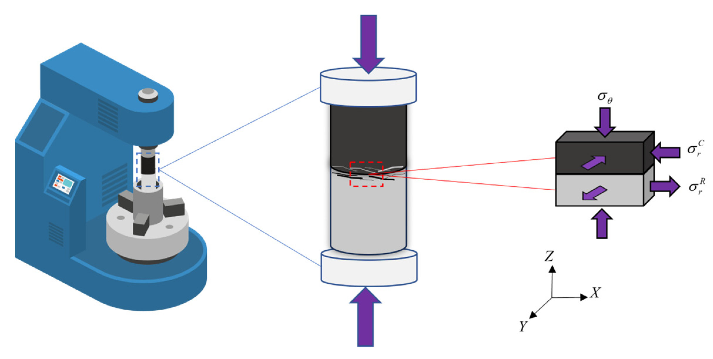
In the transition zone of the primary coal–rock composite, different interface effects will occur on the coal–rock body part. The derived stress of the coal body is horizontal tensile stress, which promotes the deformation of the rock and coal at the interface. The derived stress of the rock at the interface is horizontal compressive stress, which restricts the deformation of the rock and coal at the interface. The closer the coal sample is to the interface, the stronger the restrictive effect of the interface effect.
(3)
The coal–rock combination interface has more developed cracks, leading to more initiation points at the interface. When cracks in the rock part begin to propagate, the failure of the coal body induces the failure of the rock. After the rock fails, a large amount of energy is released and transferred to the coal body, exacerbating the degree of damage and the dynamic manifestation strength of the coal body, forming a feedback mechanism of mutual damage between the coal body and the rock body.
(4)
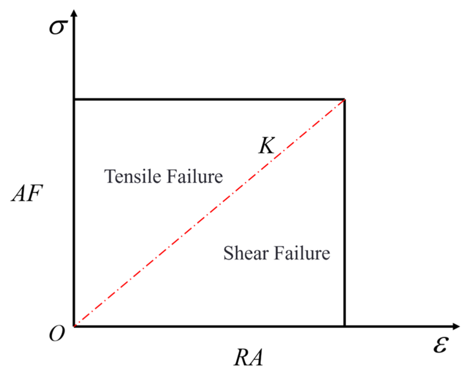
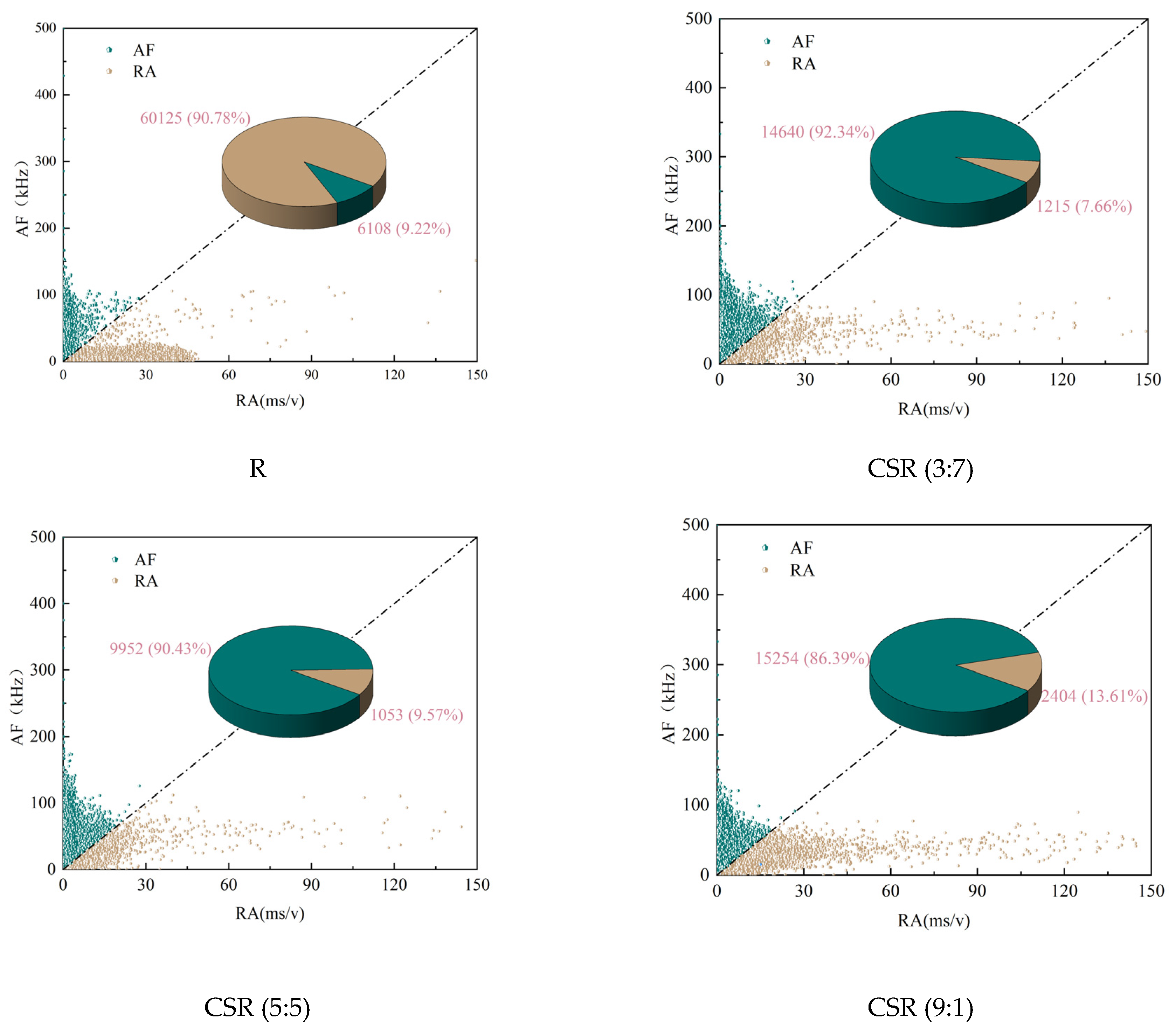
The acoustic emission signals of single-rock samples exhibit low AF and high RA characteristics, indicating shear failure. In contrast, the acoustic emission signals of single-coal samples and composite samples exhibit significant high AF and low RA characteristics, with tensile failure being the main destabilizing factor. Moreover, with the increase in the coal proportion, the proportion of RA values gradually increases, while the proportion of AF values decreases, indicating a transition from tensile failure to tensile–shear composite failure in the samples.

Author Contributions

Y.C.: Conceptualization, Methodology, Writing—original draft. X.Z.: Methodology, Validation. L.W.: Validation. Q.F.: Resources, Supervision. Q.L.: Formal analysis. All authors have read and agreed to the published version of the manuscript.

Funding

This work is supported by the National Key Research and Development Program of China (No. 2023YFC3009002), the Open Research Grant of Joint National-Local Engineering Research Centre for Safe and Precise Coal Mining (Anhui university of Science and Technology) (Grant No. EC2022021), and the National Natural Science Foundation of China (No. 52204220).

Institutional Review Board Statement

Not applicable.

Informed Consent Statement

Not applicable.

Data Availability Statement

The original contributions presented in the study are included in the article, further inquiries can be directed to the corresponding author.

Conflicts of Interest

The authors declare no conflicts of interest.

References

  1. Ding, T.; Wu, Y.; Wang, L.; Nie, Z.; Zhang, L. A Case Study Comparing Methods for Coal Thickness Identification in Complex Geological Conditions. Appl. Sci. 2024, 14, 10381. [Google Scholar] [CrossRef]
  2. Wu, R.; Wu, Y.; Sun, B.; Zhou, G.; Zheng, L. Monitoring of Overburden Failure with a Large Fractured-Height Working Face in a Deep Jurassic Coal Seam Based on the Electric Method. Appl. Sci. 2024, 14, 10293. [Google Scholar] [CrossRef]
  3. Song, H.; Zuo, J.; Liu, H.; Zuo, S. The strength characteristics and progressive failure mechanism of soft rock-coal combination samples with consideration given to interface effects. Int. J. Rock. Mech. Min. Sci. 2021, 138, 104593. [Google Scholar] [CrossRef]
  4. Yin, S.; Li, Z.; Wang, E.; Niu, Y.; Tian, H.; Li, X.; Li, H.; Yang, C. The infrared thermal effect of coal failure with different impact types and its relationship with bursting liability. Infrared Phys. Technol. 2024, 138, 105263. [Google Scholar] [CrossRef]
  5. Yin, S.; Wang, E.; Li, Z.; Zang, Z.; Liu, X.; Zhang, C.; Ding, X.; Aihemaiti, A. Multifractal and b-value nonlinear time-varying characteristics of acoustic emission for coal with different impact tendency. Measurement 2025, 248, 116896. [Google Scholar] [CrossRef]
  6. Du, F.; Wang, K.; Zhang, G.; Zhang, Y.; Zhang, G.; Wang, G. Damage characteristics of coal under different loading modes based on CT three-dimensional reconstruction. Fuel 2022, 310, 122304. [Google Scholar] [CrossRef]
  7. Liu, H.D.; Liu, S.; Xia, Z.G.; Liu, J.J.; Guo, H.; Yuan, Y.T. Study on mechanical properties and damage features of Rock-Coal-Rock combination models with defects and fillings. Geomech. Eng. 2021, 27, 239–251. [Google Scholar] [CrossRef]
  8. Yang, K.; Liu, W.J.; Ma, Y.K.; Xu, R.J.; Chi, X.L. Experimental study on impact failure characteristics of true triaxial single-side free coal-rock composite. Rock. Soil. Mech. 2022, 43, 15–27. [Google Scholar] [CrossRef]
  9. Qian, Y.; Li, Q.; Hu, Q.; Jiang, Z.; Liu, R.; Li, J.; Li, W.; Yu, C. Extraction and identification of spectrum characteristics of coal and rock hydraulic fracturing and uniaxial compression signals. Int. J. Coal Sci. Technol. 2023, 10, 53. [Google Scholar] [CrossRef]
  10. Bai, X.; Wang, Y.; He, G.; Zhou, Z.; Wang, D.; Zhang, D. Research on a permeability model of coal damaged under triaxial loading and unloading. Fuel 2023, 354, 129375. [Google Scholar] [CrossRef]
  11. Sunkpal, M.; Sherizadeh, T. Exploring the Deformation Mechanics of Coal Ribs Using the Distinct Element Modeling Approach. Rock. Mech. Rock. Eng. 2022, 55, 2879–2898. [Google Scholar] [CrossRef]
  12. Wang, K.; Fu, Q.; Xu, C.; Ai, Z.; Li, D.; Shu, L. The strength characteristics and competitive failure mechanism of primary coal-rock combination considering interface damage quantity. Fuel 2023, 352, 129057. [Google Scholar] [CrossRef]
  13. Cai, Y.B.; Wang, K.; Xu, C. Comparative Experimental Study on Deformation and Damage Characteristics of Coal-Rock Monomer and Protogenic Composite. J. Min. Sci. Technol. 2020, 5, 278–283. [Google Scholar] [CrossRef]
  14. Santiago, V.; Zabala, F.G.; Sanchez-Barra, A.J.; Deisman, N.; Chalaturnyk, R.J.; Zhong, R.; Hurter, S. Experimental investigation of the flow properties of layered coal-rock analogues. Chem. Eng. Res. Des. 2022, 186, 685–700. [Google Scholar] [CrossRef]
  15. Peng, Y.; Gao, Y.T.; Wang, W.L.; Puerkat, W.J.M.; Zhou, Y. Study on fracture mechanism of single-sided confined compression coal-rock composite. Rock. Soil. Mech. 2023, 44, 387–398. [Google Scholar] [CrossRef]
  16. Guo, Y.; Zhao, Y.; Wang, S.; Feng, G.; Zhang, Y.; Ran, H. Stress-strain-acoustic responses in failure process of coal rock with different height to diameter ratios under uniaxial compression. J. Cent. South. Univ. 2021, 28, 1724–1736. [Google Scholar] [CrossRef]
  17. Zhao, T.; Gu, X.; Guo, W.; Gong, X.; Xiao, Y.; Kong, B.; Zhang, C.-G. Influence of rock strength on the mechanical behavior and P-velocity evolution of coal-rock combination specimen. J. Mater. Res. Technol. 2021, 12, 1113–1124. [Google Scholar] [CrossRef]
  18. Lei, R.D.; Su, L.; He, P.; Hu, C.; Li, J.; Zhou, L.S. Study on acoustic emission characteristics and energy evolution of Brazilian splitting tests of coal samples with different height-diameter ratio. Coal Sci. Technol. 2024, 52, 63–77. [Google Scholar] [CrossRef]
  19. Nazarova, L.A.; Zakharov, V.N.; Shkuratnik, V.L.; Nazarov, L.A.; Protasov, M.I.; Nikolenko, P.V. Use of Tomography in Stress-Strain Analysis of Coal-Rock Mass by Solving Boundary Inverse Problems. In ISRM European Rock Mechanics Symposium Eurock; Konicek, P., Soucek, K., Konecny, P., Eds.; Elsevier Science Bv: Amsterdam, The Netherlands, 2017; pp. 1048–1055. [Google Scholar]
  20. Chen, G.B.; Li, T.; Yang, L.; Zhang, G.H.; Li, J.W.; Dong, H.J. Mechanical properties and failure mechanisms of composite bodies with different coal-rock ratios and combinations. J. Min. Ground Control Eng. 2021, 3, 84–94. [Google Scholar] [CrossRef]
  21. Fan, Y.F.; Xiao, X.C.; Xu, J.; Wu, D.; Ding, X.; Wang, L.; Lv, X.F. Influence of Coal Height on Mechanical Properties and Impact Tendency of Combined Rock-Coal. J. China Coal Soc. 2020, 45, 649–659. [Google Scholar] [CrossRef]
  22. Zhang, H.; Lu, C.P.; Liu, B.; Liu, Y.; Zhang, N.; Wang, H.Y. Numerical investigation on crack development and energy evolution of stressed coal-rock combination. Int. J. Rock. Mech. Min. Sci. 2020, 133, 104417. [Google Scholar] [CrossRef]
  23. Tahmasebinia, F.; Zhang, C.; Canbulat, I.; Sepasgozar, S.; Saydam, S. A Novel Damage Model for Strata Layers and Coal Mass. Energies 2020, 13, 1928. [Google Scholar] [CrossRef]
  24. Hu, Q.T.; Liu, R.H.; Li, Q.G.; Qian, Y.N.; Ling, F.P. Acoustic Emission Characteristics Stucty of Typical Coal Rock Failure under Uniaxial Compression. Chin. J. Undergr. Space Eng. 2023, 19, 1769–1781. [Google Scholar]
Figure 1. Schematic diagram of the specimens.
Applsci 15 03091 g001
Figure 2. Schematic diagram of experimental system.
Applsci 15 03091 g002
Figure 3. Stress–strain curves of single-rock sample, single-coal sample, and combinations.
Applsci 15 03091 g003
Figure 4. Peak stress and elastic modulus of single-rock sample, single-coal sample, and combinations.
Applsci 15 03091 g004
Figure 5. Accumulative AE counts.
Applsci 15 03091 g005
Figure 6. Damage characteristics and sketches.
Applsci 15 03091 g006
Figure 7. Schematic diagram of rock fracture mechanism based on RA and AF values.
Applsci 15 03091 g007
Figure 8. RA–AF of single-coal, single-rock, and combinations.
Applsci 15 03091 g008aApplsci 15 03091 g008b
Figure 9. Elastic strain energy and dissipation energy relationship curve.
Applsci 15 03091 g009
Figure 10. Energy evolution diagram of the sample.
Applsci 15 03091 g010
Figure 11. Schematic diagram of force on the combination.
Applsci 15 03091 g011
Table 1. Sample information.
SampleNumberHeight (d × h)/mmCoal–Rock Ratio
Raw coalC (10:0)49.58 (coal) × 100.3410:0
MudstoneR (0:10)49.74 (coal) × 100.110:10
Artificial coal–rock combinationCR (5:5)50.22 (coal) × 100.235:5
Primary coal–rock combinationCSR (5:5)49.86 (coal) × 100.175:5
Primary coal–rock combinationCSR (3:7)49.96 (coal) × 100.163:7
Primary coal–rock combinationCSR (9:1)50.11 (coal) × 100.379:1
Disclaimer/Publisher’s Note: The statements, opinions and data contained in all publications are solely those of the individual author(s) and contributor(s) and not of MDPI and/or the editor(s). MDPI and/or the editor(s) disclaim responsibility for any injury to people or property resulting from any ideas, methods, instructions or products referred to in the content.

