Article

Challenge–Response Pair Mechanisms and Multi-Factor Authentication Schemes to Protect Private Keys

by
Bertrand Francis Cambou
* and
Mahafujul Alam
School of Informatics, Computing and Cyber Systems, Northern Arizona University, Flagstaff, AZ 86011, USA
*
Author to whom correspondence should be addressed.
Appl. Sci. 2025, 15(6), 3089; https://doi.org/10.3390/app15063089
Submission received: 20 January 2025 / Revised: 7 March 2025 / Accepted: 10 March 2025 / Published: 12 March 2025
(This article belongs to the Section Computing and Artificial Intelligence)

Abstract

:

Featured Application

Protection of private keys for signing transactions in public key infrastructures for crypto wallets and terminal devices.

Abstract

Crypto wallets store and protect the private keys needed to sign transactions for crypto currencies; they are secured by multi-factor authentication schemes. However, the loss of a wallet, or a dysfunctional factor of authentication, can be catastrophic, as the keys are then lost as well as the crypto currencies. Such difficult tradeoffs between the protection of the private keys and factors of authentication that are easy to use are also present in public key infrastructures, banking cards, smartphones and smartcards. In this paper, we present protocols based on novel challenge–response pair mechanisms that protect private keys, while using factors of authentication that can be lost or misplaced without negative consequences. Examples of factors that are analyzed include passwords, tokens, wearable devices, biometry, and blockchain-based non-fungible tokens. In normal operations, the terminal device uses all factors of authentication to retrieve an ephemeral key, decrypt the private key, and finally sign a transaction. With our solution, users can download the software stack into multiple terminal devices, turning all of them into backups. We present a zero-knowledge multi-factor authentication scheme allowing the secure recovery of private keys when one of the factors is lost, such as the token. The challenge–response pair mechanisms also enable a novel key pair generation protocol in which private keys can be kept secret by the user, while a Keystore can securely authenticate the user and transmit the public key to a distributed network. The standardized LWE post-quantum cryptographic CRYSTALS Dilithium protocol was selected in the experimental section.

1. Introduction

Developing methods to protect private keys for signing or decrypting messages in public key infrastructure (PKI) applications is a vibrant field in the cyber security space. The asymmetrical cryptography underneath PKI enables two essential functions: the secure transfer of digital information through a public network, or the signing of electronic messages [1,2,3,4,5,6]. The early cryptography methods such as RSA and elliptic curve cryptography (ECC) will be replaced over time by post-quantum cryptographic (PQC) algorithms such as CRYSTALS Dilithium and Kyber [7,8,9,10]. These methods are leveraging known mathematical methods such as lattices or code computations [11,12,13,14]. The generation, distribution, and storage of the public–private key pairs needed in asymmetrical cryptographic schemes is a difficult set of tasks, as the private key should remain totally secret. These private keys are used to decrypt the digital information encrypted with the public key, or to sign electronic messages that can be verified with the public key. Traditional applications of PKI are broad; they include securing banking cards, peer-to-peer information sharing, and electronic transactions. When combined with blockchains, PKI-based solutions enable a new class of important applications such as signing transactions with crypto currencies [15,16,17,18,19,20,21,22] and blockchains [23,24,25,26,27,28,29]. One of the main roles of crypto wallets is to protect private keys, without risking losing them [30,31,32,33,34,35]; existing crypto wallets are prone to security breaches [36]. By contrast, our proposed protocols are zero-knowledge and prevent opponents finding the factors sequentially. This allows the implementation of recovery protocols, mitigating the loss of one factor without weakening security. Refs. [37,38,39,40,41,42] present various multi-factor authentication (MFA) schemes to protect private keys in PKI networks, including the use of blockchains. Our implementation integrates blockchains as part of the non-fungible token, creating a reference table that is combined with the tables generated from other factors of authentication. In addition to MFA, solutions include the use of blockchains, fragmenting and encrypting the private keys, and combining hardware with software remedies [43,44,45,46,47,48,49,50,51]. In our implementation, we elected to encrypt the private keys with an ephemeral key that we erase after the encryption cycle and can only recover with the MFAs. Encrypting the private key with a key that we store on a terminal device is not secure enough when the opponent has access to the terminal device.
One method to enhance MFA security is to use Physical Unclonable Functions (PUFs), which can offer reliable authentication, and on-demand key generation [52,53,54,55,56,57]. Rather than storing the key encrypting the private keys in the device, the key is generated with the PUF and a challenge–response pair mechanism. However, storing both the challenges and the PUF in the terminal device offers limited security, as the opponent can generate the responses, and use them to decrypt the private keys. We propose mounting the PUF on a removable token that is kept separate from the terminal device, while only the challenges are stored in the terminal device. The users have to plug the token into the device to retrieve the private key, which enhances security. The use of MFA to protect crypto wallets and other terminal devices storing private keys could be risky for users because a loss of these factors could have catastrophic effect [58,59,60]. In this paper, we propose methods to recover the loss of one factor of authentication. Another issue with PKI is the generation of the key pairs, which are currently controlled by service providers such as Keystores, and Hardware Security Module (HSM) providers. Here, we worry about insider attacks, and various other attacks [61,62,63]. An important technology presented in this paper is to allow each user to always keep the private keys secret, and away from the Keystores and HSM, while establishing clear authentication for users during the key pair generation cycles.
The paper is organized as follows:
  • In Section 2, the paper describes secure MFA schemes that are easy to use, combined with methods to generate private keys that truly protect users’ privacy. We describe a challenge–response pair (CRP) mechanism that is zero-knowledge, with N authentication factors such as tokens, biometry, and blockchain-based virtual tokens. During normal operations, the terminal device uses all factors of authentication to retrieve the private keys Sk and sign a document or a financial transaction.
  • In Section 3, we suggest protocols based on a scheme in which the private keys are generated and kept secret by the user, while a service entity, a Keystore corporation, can authenticate the user, and transmit the public keys to the cloud, or a certificate authority (CA). The standardized LWE post-quantum cryptographic CRYSTALS Dilithium is suggested in the implementation of this last feature.
  • In Section 4, we present the experimental work, the generation of reference tables from three important factors of authentication: PUF-based physical tokens, template-less biometry, and blockchain-based virtual tokens.
  • In Section 5, we further analyze and benchmark the protocols and discuss methods to handle the loss of the factors of authentication. This is followed by the conclusion in Section 6 and suggested future work.

2. Description of the Protocol Protecting Private Keys with MFA

2.1. Factors of Authentication for the MFA

In addition to passwords, multiple factors of choice can be selected to protect a private key. Examples include but are not limited to the following:
A physical token with a SRAM-based physical unclonable function (PUF) that can support a CRP mechanism. The challenges are a set of n × n addresses pointing at the SRAM; the responses are the reading of the SRAM at these n × n positions. Each SRAM device is unique when submitted to power-off power-on cycles, each cell awaking either as a consistent “0” or “1”. Small portions of these cells are flaky, awaking randomly as a “0” and a “1”, which we recorded with a third state, “x”.
A biometric scheme supporting a CRP mechanism. For example, the biometric images are described by a set of L landmarks. The challenges are a set of “n” addresses pointing at the image. The responses are the reading of the distances between a position in the image and the L landmark. The distances can be converted into an s-bit data stream; thereby the total size of the responses is n × ( s × L ) . When submitted to repetitive enrollment cycles, the streams of responses are consistent “0”s or “1”s Small portions of the information are flaky, awaking randomly as a “0” and a “1”; they can be recorded with a third state, “x”.
A virtual token can be generated from a digital file resulting from the computation of a chain of information and its blockchain, which supports a CRP mechanism. The challenges are a set of n × n addresses pointing at the digital file; the responses are the reading of the digital file at these n × n positions.

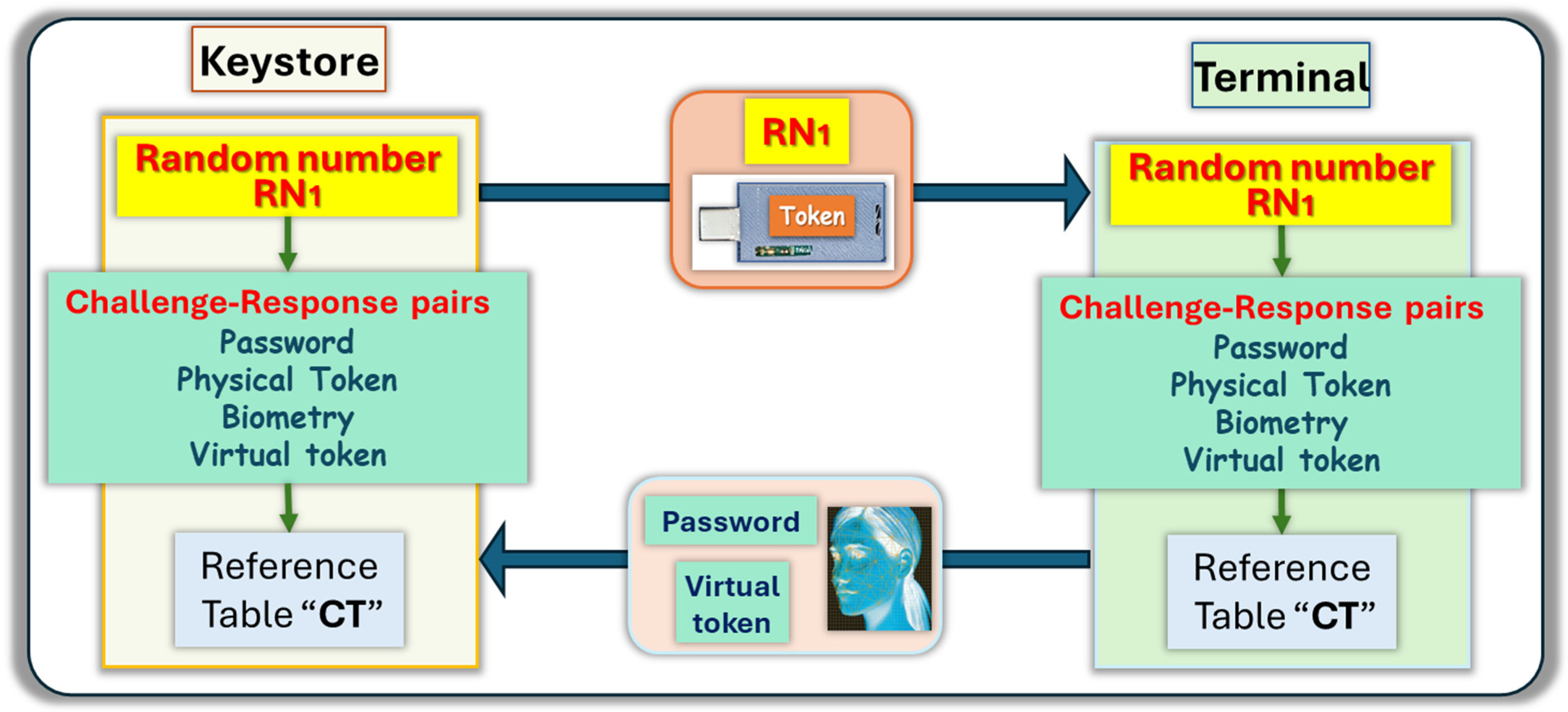
2.2. Description of the Enrollment Cycle

An enrollment cycle is needed to record the reference tables generated from the multiple factors of the MFA. The operation can be solely controlled by a user with a terminal device equipped with physical tokens, biometric schemes, and virtual tokens. The enrollment cycle can also be completed in cooperation with a service company, called a Keystore, which provides the first random number RN1, and the physical token, as shown in Figure 1.
The first random number is concatenated with the password to generate the set of responses used by each of the multiple factors of authentication, for example a physical token, biometric scheme, and virtual token. From each factor, an n × n reference table is generated from the responses: CT-T from the physical token, CT-Bio from the biometric image, CT-VT from the virtual token. A combined n × n reference table CT is computed from the multiple reference tables, for example, CT-T, CT-bio, and CT-VT. Each position of the three tables contains one of the three states, “0”, “1”, or “x”. One way to compute the combined table is to apply an addition modulo 2 as follows:
  • Let a i j be the state contained at each position ( i , j ) of the n × n table CT-T generated from the physical token.
  • Let b i j be the state contained at each position ( i , j ) of the n × n table CT-bio generated from the biometric scheme.
  • Let c i j be the state contained at each position ( i , j ) of the n × n table CT-VT generated from the biometric scheme.
  • Let d i j be the state contained at each position ( i , j ) of the resulting n × n table CT computed from CT-T, CT-Bio, and CT-VT. They are computed as follows:
    If all a i j , b i j , and c i j consist only of “0” or “1” states then:
    d i j = ( a i j + b i j + c i j )   m o d 2 = a i j   b i j c i j  
    Otherwise: d i j = x
For each position, when the information contained in one of the tables is a flaky state “x”, this results in a state of “x” in the combined table CT. The addition mod 2 with three factors can be generalized to compute reference tables with N factors of authentication. We then use the notation a i j ) k for the state contained at position ( i , j ) of the table generated from the factor k , with k { 1 , N } . The computed d i j is given by:
 ○
If all a i j ) k regardless of k are states “0” or “1”, then:
d i j = k = 1 k = N a i j ) k   m o d 2 ;  
 ○
Otherwise: d i j = x
The small example shown in Figure 2 describes the computation of three factors, k = 3 and n = 8 . The reference tables CT-T generated from the token, and CT-Bio from the biometric image contain flaky positions; however, the table CT-VT, which is generated from a blockchain-based virtual token, contains only states “0” and “1”.

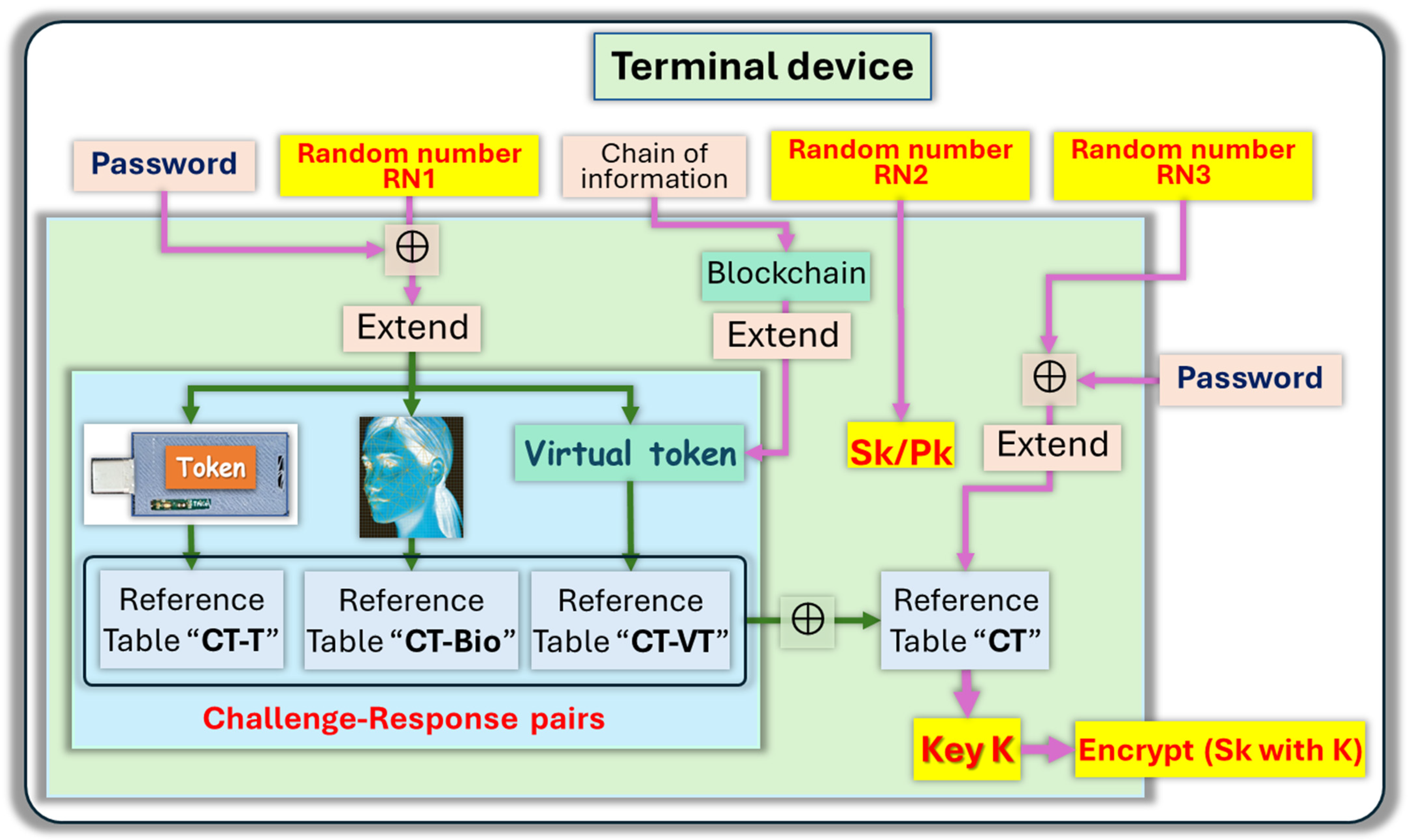
2.3. Generation of Ephemeral Keys

We assume that the public–private key pair Pk/Sk is generated with a second random number RN2 with a protocol such as the one described in Section 3. To protect the private key Sk, the user randomly picks a third number RN3, concatenated with the password to generate a set of challenges pointing at m positions in the combined reference table CT. An m-bit long ephemeral key K is computed from the responses. The resulting key K is used to encrypt the private key Sk needed by the PKI scheme to sign transactions. The terminal device can be a crypto wallet, a smartcard, a token, a smartphone, or a personal computer. After encryption, the terminal device keeps in storage both random numbers RN1, RN3, and the encrypted private key SK. All other information is erased, which includes all reference tables CT-T, CT-Bio, CT-VT, CT, and the ephemeral key K. The user can recover the private key SK with RN1, RN3, and the encrypted key SK, as shown in Figure 3, by plugging in the physical token, presenting their visual image, and computing the virtual token. Liveness tests can be inserted in the protocol to avoid third parties passing the visual test with an image of the user. The protocol based on biometric images is “template-less”, which protects the privacy of the user. The user can prepare backup hardware devices by downloading the same software stack, as well as RN1, RN3, and the encrypted key SK. Such a scheme can, for example, protect a user against the loss of a crypto wallet, without compromising security, as the same MFA is always needed to retrieve the private key Sk. At every cycle, the user can easily pick a new random number RN3 to generate a new ephemeral key K, thereby encrypting the private key Sk with a one-time use key. This prevents attacks such as side channel attacks finding the ephemeral key during decryption cycles.

2.4. Role of the Keystore

One of the problems that has to be comprehended is the potential loss or failure of the token. One possible mitigation can come from a Keystore corporation that can store the reference table CT-T generated during an enrollment cycle from the token. When the token is lost, the user can ask the Keystore to transmit the table CT-T, then use it as part of the full MFA process. Such a recovery operation is still relatively secure, as malicious parties can do very little from the table CT. To intercept the ephemeral key K, the malicious parties still need RN1, RN3, the password, the biometric information, and the virtual token. A new token and a new enrollment cycle will be needed to re-establish the full protection. The Keystore corporation can also provide valuable services to reduce the rates of errors in the key recovery process, and the use of ternary cryptographic schemes. Rather than generating the tables CT-T from the physical token and CT-bio from the biometric scheme by a single operation, multiple cycles allow a better identification of the flaky positions’ “x”. For example, 100 repetitive cycles have been successfully demonstrated to catch 99.99% of the flaky positions. The Keystore corporation can generate a masking table CTMask from CT to capture the flaky positions. For example, the position ( i , j ) of the masking table CTMask can be a “0” when a solid state of “0” or “1” is detected, and a state of “1” when the position is flaky. The Keystore will transmit the masking table CTMask to the user, who can skip the flaky positions when generating the ephemeral key K. The resulting key K will have a lower rate of bad bits during subsequent recovery cycles and can be corrected by ultra-light schemes.

3. Description of a Protocol for PKI Enhancing Privacy with MFA

The MFA protocol with CRP for protecting private keys described in Section 2 can be combined with another key generation scheme for PKI, such as the protocol described in [64]. Here, we wish to generate PQC safe key pairs for a Distributed Network in which the Keystore and the users jointly generate public keys while the private keys are generated and always kept secret by the user.

3.1. Enrollment Cycle with Private Key Generation

After completion of the enrollment cycle described in Section 1, both the Keystore and the user concurrently generate the same combined reference table CT. During this operation, the client is physically present in the office of the Keystore and downloads the “Crypto Wallet” on to their smartphone. An in-person cycle like that described can be carried out through video conferencing. In this case, the visual image of the user is captured during the conference, while the token is shipped to the physical address of the user. A virtual session could, for example, facilitate the replacement of a lost token. A second part of the enrollment cycle to generate the public–private key pair is shown in Figure 4. In this example, the standardized post-quantum cryptographic (PQC) Dilithium was implemented. At the end of the enrollment cycle, the Keystore makes the user ID and the public key Pk of the user “public” by posting it online. The user needs to keep in storage the random numbers RN1 and RN2, as well as C, and indeed the encrypted private key Sk. The step-by-step operations are shown below:
  • Initial operations driven by the Keystore corporation KSC:
    Generation of the reference table CT:
    RN1’   RN1⊕PW: with random number RN1, and password PW
    n challenges  RN1’: with XoF function.
    With CRP mechanisms, they generate 4 n × n reference tables
    (1)
    CT-bio   n challenges: CRP from the facial image
    (2)
    CT-T   n challenges: CRP from a token
    (3)
    CT-VT    n challenges: CRP from a virtual token
    (4)
    CT (CT-bio)⊕(CT-T)⊕(CT-VT): concatenation
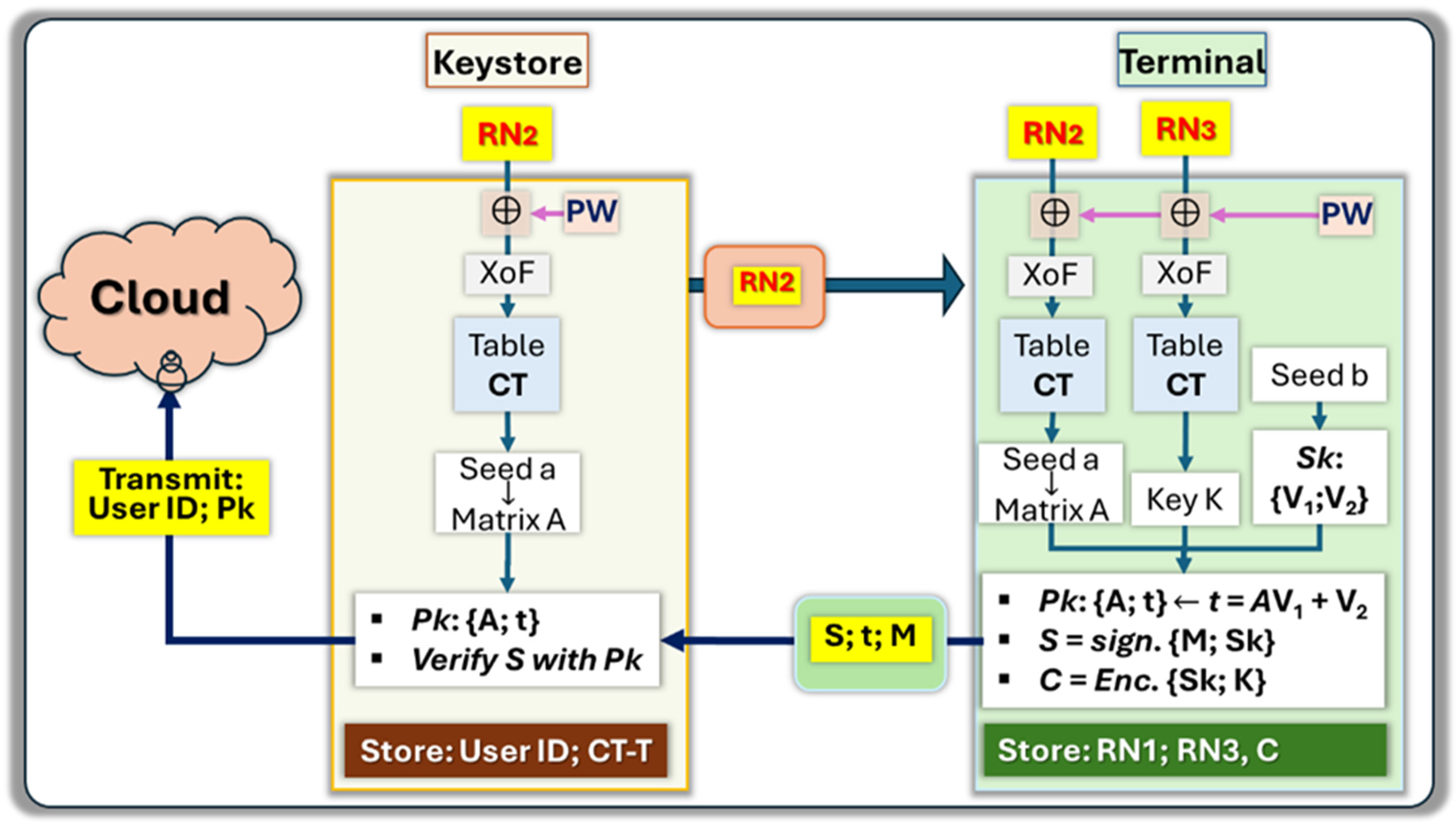
    Generation of Seed-a:
    RN2’   RN2⊕PW: with random number RN2, and password PW
    n challenges RN2’: with XoF function.
    Seed-a    n challenges: CRP mechanism with table CT
    KSC transmit RN1 and RN2 by email to the client’s smartphone
  • Operations driven by the “Crypto Wallet” apps in the client’s phone:
    Generation of Seed-a following the same steps as above:
    Seed-a   RN1, RN2, PW, image, token, and virtual token.
    Generate a public/private key pair with Dilithium and sign M:
    Matrix-A  Seed-a: with XoF function
    Vectors V1 and V2  Seed-b; Private key Sk: {V1; V2}
    Vector t   A V1 + V2; Public key Pk: {Seed-a; t }
    S S i g n ( M ,   S k ) : Sign message M with Sk
    Protect the private key Sk:
    RN3’   RN3⊕PW’: with random number RN3, and PW’
    m challenges RN3’: with XoF function
    Key K    m challenges: with a CRP mechanism and table CT
    C E n c r y p t ( S k ,   K ) : Encrypt Sk with AES and K
    Transmit by email the message M, the signature S and vector t to KSC
    Store RN2; RN3; and C
  • Final verification, and posting of the public keys
    Between seed-a that was generated from the table CT, and t from the user, KSC is in possession of the full public key Pk: {Seed-a; t}
    KSC can verify the signature S of message M with Pk
    KSC transmits to a Certificate Authority, or the cloud, client’s ID and Pk
    KSC only keeps record of the crypto-table of the token CT-T

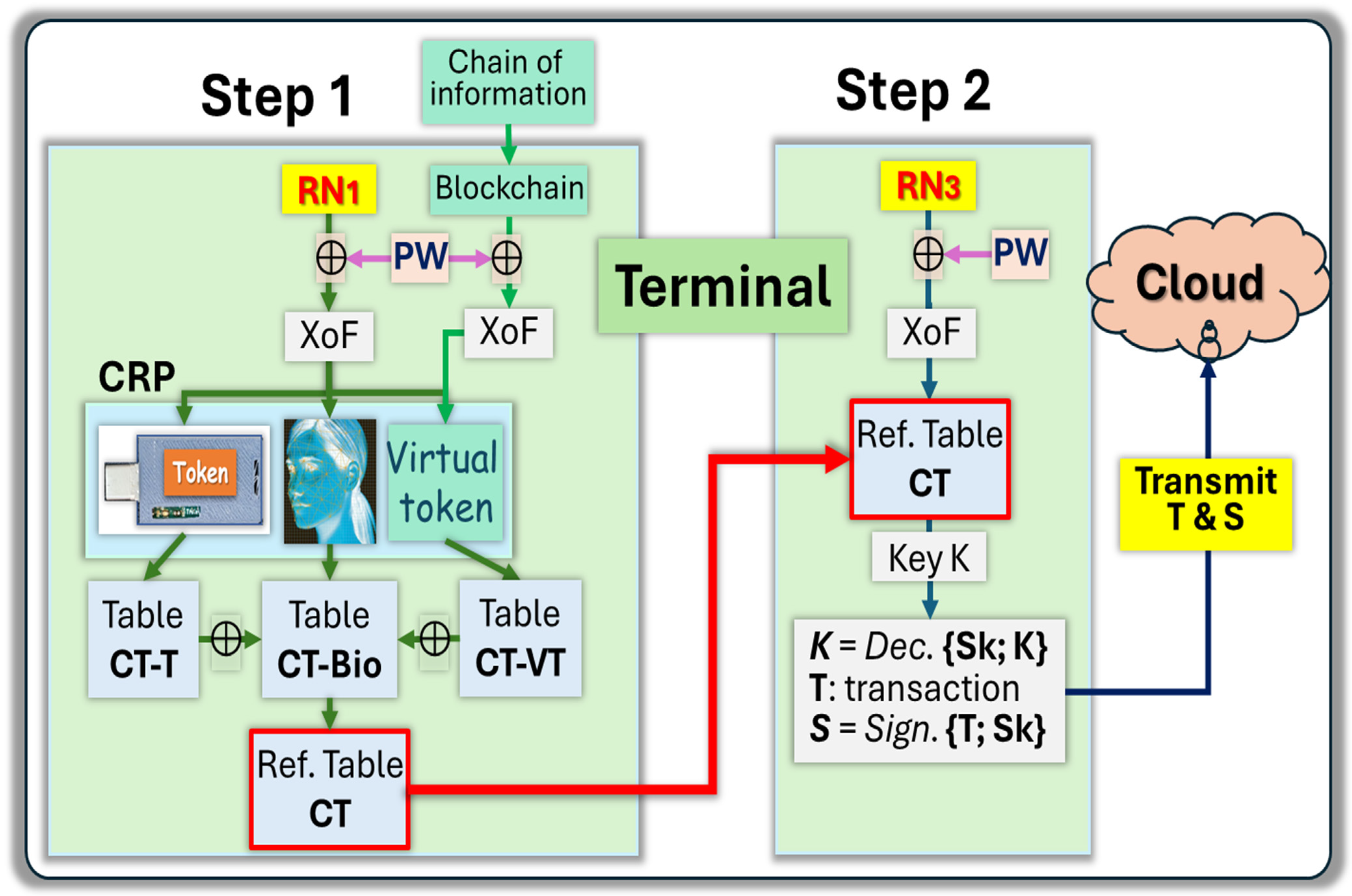
3.2. Signing a Transaction in a PKI Environment

Within a PKI environment, the user needs to retrieve private key Sk, sign a transaction N, and transmit both the transaction and its signature to the cloud. The transaction can then be openly verified by third parties with the public key. The protocol (see block diagram of Figure 5) is the following:
  • The user can recover the reference table CT with RN1 by plugging in the physical token, presenting their visual image, and computing the virtual token. Liveness tests can be inserted into the protocol to avoid third parties passing the visual test with an image of the user. The use of biometric images is “template-less”, which protects the privacy of the user.
  • The user can recover the ephemeral key K from the reference table CT and RN3 with a CRP mechanism.
  • The ephemeral key allows the decryption of Sk the private key.
  • Sk is used to compute S, the signature of transaction T.
  • The user transmits signature S, transaction T, and the public key Pk online.
  • The signature can be openly verified by third parties with access to S, N, and Pk.
As presented at the end of Section 2, the use of a masking table CTmask can reduce the bit error rates. Additional error management schemes and error correcting schemes can be inserted to ensure that the ephemeral key K is exactly the same as the one generated during the enrollment cycle.

4. Experimental Section and Analysis

4.1. Generation of Reference Tables from PUF-Based Physical Tokens

Physically Unclonable Functions (PUFs) are security primitives that extract unique information from a device to generate a distinctive signature [52]. This approach significantly enhances security by enabling the creation of device-specific signatures or true random numbers, which can be directly integrated into cryptographic protocols, thereby strengthening device security. Most existing research explores the use of PUFs for generating cryptographic keys or seeds by challenging various addresses of the device to obtain unique responses for key creation and verification [64]. In this work, the generation of the reference table is tailored differently for the server and client sides. Instead of using a conventional 256-bit address for the PUF, we construct a reference table of dimensions such as 256 × 256. On the server side, the PUF is read multiple times to thoroughly characterize its behavior for enrollment purposes. Specifically, this research employs Static Random Access Memory (SRAM)-based PUFs to capture three possible states: “0”, “1”, and “X”, thereby obtaining comprehensive information about all PUF cells. For experimentation, IS61LV6416 1Mb SRAM chips were utilized, providing 1,048,576 cells, each read hundreds of times. The server can retain this detailed information for the recovery process, safeguarding against token damage or loss. The physical token is then delivered to the user, where it generates the same reference table using a single read.
Experimental section: We conducted an enrollment session comprising 1000 reads for 1970 token table generation cycles using an enrollment file i.e., the comparison of all those 1000 reads on the server side using challenges. Clients use the same challenges to produce the same table using one single read. On the server side, after 1000 reads, we obtain our enrollment file, and, during each cycle, we read states “0” or “1” of each cell of the IS61LV6416 1M SRAM chip and store the binary read; we compare each read to calculate the average state of each cell. Cells consistently producing “1” or “0” were marked as stable “1”s and “0”s, respectively, while cells exhibiting bit flips were labeled as “X”. This process resulted in a ternary mapping (“0”, “1”, “X”) of the entire SRAM-based PUF on the server side. On the client side, a single read of the SRAM PUF yielded a binary state (“0” and “1”) without comparisons to other reads. For the analysis, 65,536 random addresses were generated, shared between the client and the server, and used to create reference tables for both sides. As shown in Figure 6, the Kernel Density Estimation (KDE) highlights the proportions of “0” and “1” for both the client and the server, and the distribution of “X” on the server.

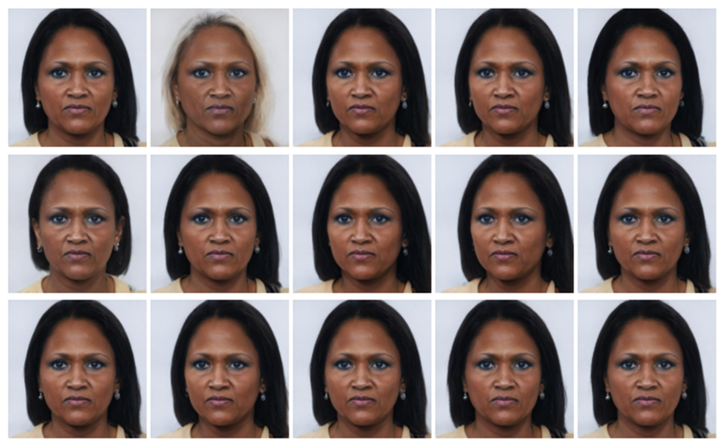
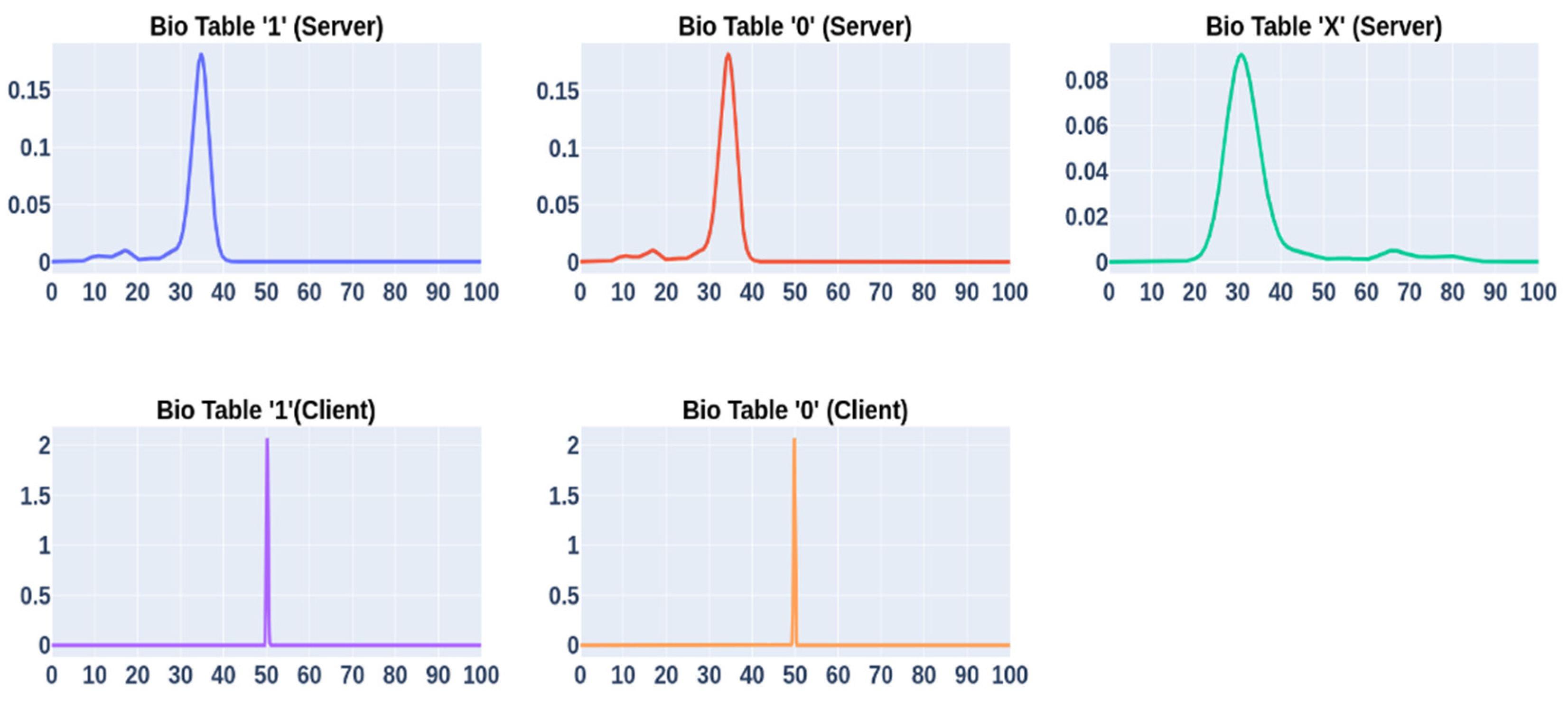
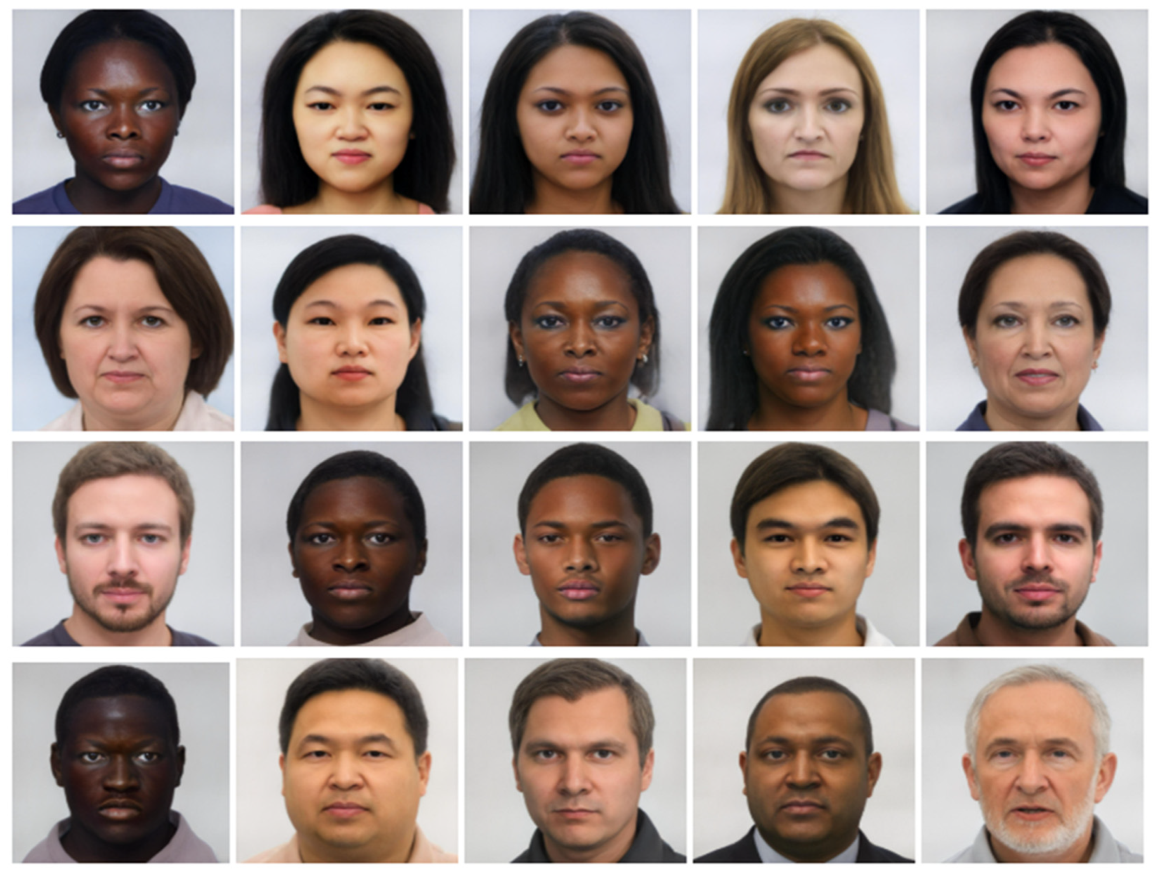
4.2. Generation of Reference Tables from Biometric Images

Using facial images as PUFs is a relatively novel concept, enabling the generation of cryptographically secure keys for authentication. While numerous methods for facial recognition have been researched, the use of facial images for cryptographic key verification offers heightened security and better protection of users’ biometric data. Recent studies have introduced unique techniques, such as placing landmarks on facial images and calculating distances between random points and these landmarks. These distances are unique due to the individuality of facial structures influenced by factors such as age, ethnicity, and other biometric traits, ensuring that the placement of landmarks is specific to each individual. However, challenges such as the “twin problem” persist, as existing facial recognition techniques struggle to differentiate between identical twins [65]. In our proposed technique, the landmark placement relies on unique facial expressions during the enrollment session, ensuring the landmarks’ positions are distinct to the user. Additionally, incorporating a user-defined unique password introduces random positions for calculating landmark distances, providing an extra layer of security and effectively mitigating the twin problem. The generation of a reference table from biometric images represents an innovative approach, with limited research available on this topic. Our work demonstrates promising results regarding the usability and security of reference tables generated using biometric data, following a methodology similar to that used for token-based PUFs.
Experimental section: On the server side, multiple facial images of an individual are processed by applying landmarking techniques to each image and calculating the distances between random challenge points and landmarks. Figure 7 provides an example of the enrollment images. As we can see, there are 15 images where the user changed her angle, hair color, and style. We aimed to capture the natural movement of an individual during the enrollment phase. Although it may seem counterintuitive to change hair color during this phase, we included that image for authentication purposes, considering that the user might change their hair color later. Additionally, we observed that hair color does not impact the landmark placement technology and does not impact the verification of the user.
The results from each image are compared to create a ternary representation, where “0” and “1” denote stable positions across all frames, and “X” represents flaky positions. The generation of ternary states using multiple facial images is an ongoing research endeavor, with results currently in the process of publication. In brief, our methodology calculates distances between 64 landmarks and 256 random challenge points on facial images. Each distance is converted into a 4-bit gray code representation, ultimately producing a 65,536-bit representation of the facial image. These representations are then compared across enrollment images to establish the ternary states. To ensure security, the reference table containing the ternary states is not stored on the server. Furthermore, since the challenge positions are entirely random, reconstructing the original facial image from the reference table is computationally infeasible. For experimentation, we utilized 6000 AI-generated facial images from 400 individuals, with each individual represented by 15 images. On the server side, all 15 images were used to create the reference biometric table, while the client-side used a single image to generate binary states (“0” and “1”). Figure 8 illustrates the comparison between the reference tables generated by the server and the client. The results are clear and effectively demonstrate the feasibility of the approach. Additionally, the percentage of stable “1”s and “0”s and unstable “X”s is around 30%. This is highly dependent on the binary representation of the raw distances as well as the gray code. Increasing the binary representation value of the raw distance as well as gray code size results in a higher number of unstable cells.
For this experiment, we are currently using binary representation of 7 bits, cutting the 3 most significant bits (MSB) and converting the resulting 4 bits with gray code to reduce the error rates due to small changes occurring between subsequent facial images. All raw distances must be normalized in the same range, for example by keeping the eye-to-eye distance constant. All normalized distances are converted to 7-bit binary streams through analog-to-digital (ADC) conversion. Then, we discard the 3 MSB bits and only keep a 4-bit binary representation of the raw distance. This allows us to convert the 4-bit streams into 4-bit gray code. Cutting the MSB does not degrade the precision in distance measurements, as the fewest bits contain the information significantly relevant to this method. However, further increasing the number of bits of the ADC conversion to 8 bits or more leads to a higher percentage of fuzziness, and “X” states.

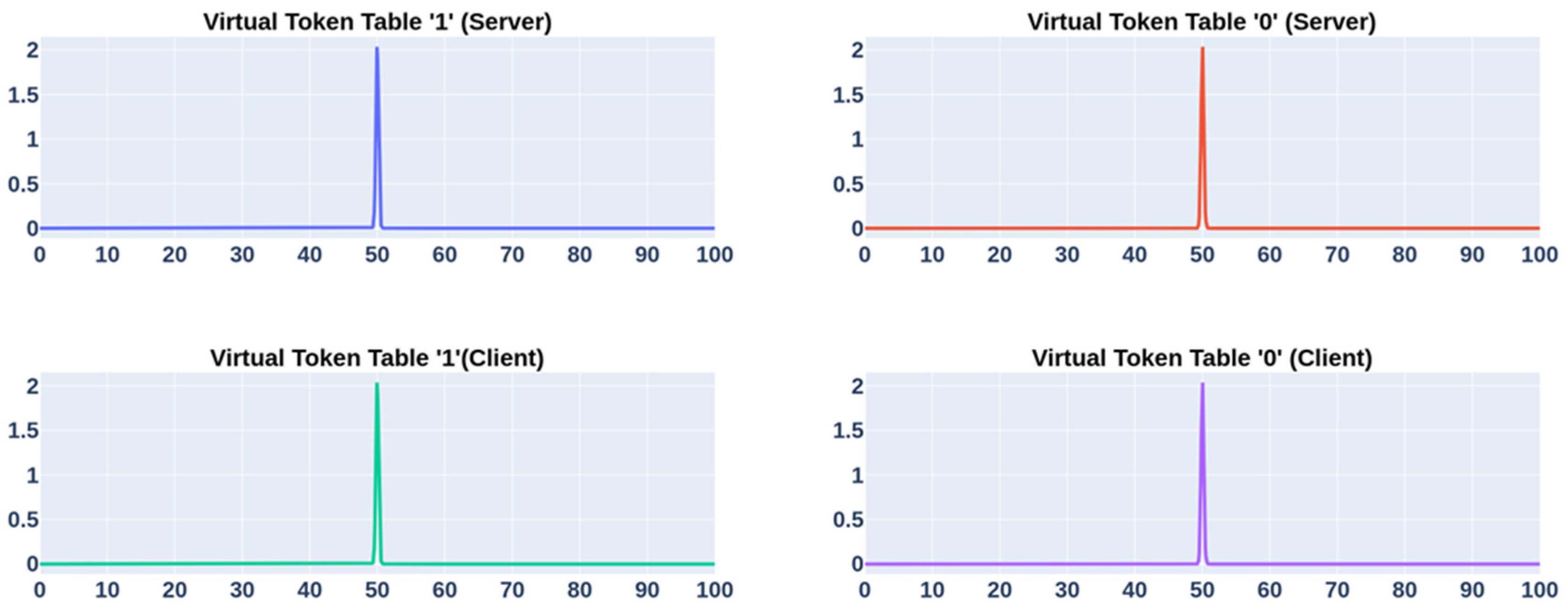
4.3. Generation of Reference Tables from Blockchain-Based Virtual Tokens

The objective is to generate reference tables from virtual tokens that can be merged with the reference tables generated from tokens, biometric images, and other MFAs. This is carried out via the following two-step operation. First, the virtual tokens need to be generated from a range of digital files, blockchains, or non-fungible tokens (NFT). The information used in this first operation could be distributed in a public network, openly verifiable. During the second operation, n × n positions in the virtual tokens are selected to generate the reference table CT-VT. Unlike the tokens generated from real tokens and visual images, CT-VT exclusively contains states of “0”s and “1”s, as the tracking of fuzzy positions is no longer needed. An example of experimentally generated information is shown in Figure 9. In this protocol, an infinite number of CT-VT reference tables can be generated.

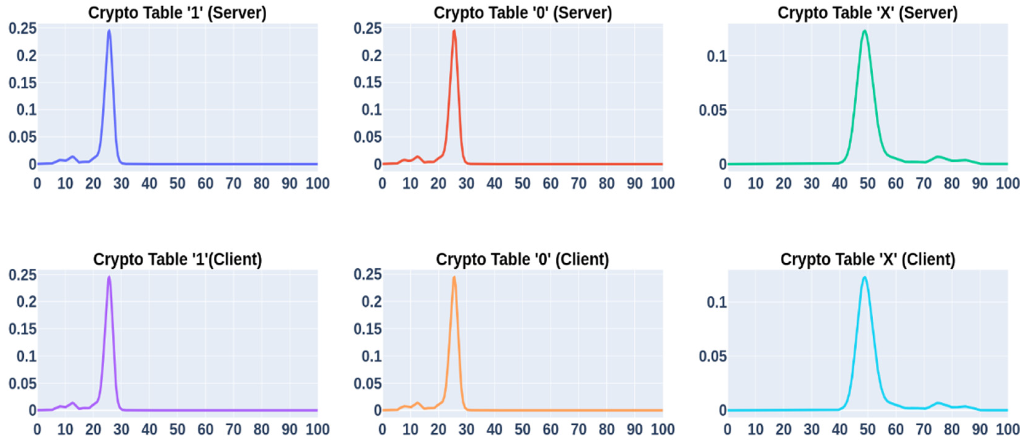
4.4. Combination of Multiple Factors

In the described protocol, the final reference table, or crypto table, is a combination of three components: the token table, the biometric table, and the virtual token table. Since the client side lacks information about ternary positions, the server sends the ternary table to the client. The client then superimposes this table onto its locally generated crypto table to produce a ternary state. Both the server and client utilize the same Random Number 2 (RN2) and password to generate identical challenges, which are used to produce a 256-bit seed for the ML-DSA44 digital signature, ultimately generating the public key.
To ensure a 256-bit key comprising only “0” and “1”, the protocol creates multiple times more challenges than are required for both the server and client crypto tables, which include ternary states. These ternary positions cannot be used directly for post-quantum digital signatures. Afterward, all “X” positions are filtered out, leaving only the stable “0” and “1” positions. Typically, the filtered list contains more than 256 stable cells. To resolve this, a random sampling technique is employed to select 256 elements without duplicates from the filtered list. The user’s password serves as the seed for this sampling process, ensuring consistent selection of positions on both the server and client sides.
Despite these measures, occasional errors may occur. To address this, a Response-Based Cryptography (RBC) error correction scheme is applied. RBC uses an exhaustive search to find the correct key, with a time limit of 5 s to prevent brute force attacks. This time constraint also acts as a security feature. Additionally, a fragmentation level is applied, splitting the 256-bit seed into smaller chunks (e.g., 2, 4, 8, or 16), and padding each chunk to make it 256 bits long (fragmentation level 1 means the whole seed is one chunk). The padding data are derived directly from RN2. For example, at a fragmentation level of 4, the 256-bit seed is divided into four 64-bit chunks, each requiring an additional 192 bits. The first 192 bits of RN2 are extracted and used as padding before being hashed. Figure 10 illustrates the seed error distribution across different fragmentation levels.
These results highlight the robustness of the approach in generating secure keys while maintaining high efficiency. As the figure illustrates, most errors are concentrated around 1, 2, 3, 4 number of errors; therefore, our error correction scheme RBC can be slow to resolve 5- to 6-bit errors.
Statistical analysis: The tests were conducted using an Intel® Core™ i9-9900K CPU @ 3.60 GHz processor. A total of 6000 AI-generated images were utilized, representing 400 individuals equally divided between 200 males and 200 females. The facial dataset was designed to be diverse, encompassing three distinct age ranges (20–34, 35–50, 51–65) and five skin tone levels to reflect various ethnicities; see Figure 11. Initially, 10,000 images were generated using a generative AI model with specific requirements and purchased from Generated Photos [66]. For the enrollment process or the generation of the biometric reference table, 15 images per individual were used. The tokenized PUF was built using an STM32F401RBT microcontroller unit (MCU) and IS61LV6416 SRAM. Each SRAM module consists of 65,536 words, providing access to 1,048,576 unique bits. For Response-Based Cryptography (RBC), we tested five different fragmentation levels. Each fragmentation level underwent 400 authentication cycles, resulting in a total of 2000 authentication cycles. As we have tried to verify both the real and wrong person for a test, our total test count would be 4000. During our experiment, we found that, sometimes, the challenges could not produce a stable key from the crypto table due to high number of flaky “X” cells. As the process is completely random, we could not control the process other than by increasing the number of challenges.
Finally, we gathered 1970 verification test results for the False Reject Test (FRR), which verifies the right person, and 1968 verification test results for the False Acceptance Rate Test (FAR), which tries to verify with the wrong person. Table 1 represents the results of the signing verification for both FRR and FAR tests.
In Table 2, we analyze the verification percentages based on gender, age range, and skin tone enrollment. As shown in Figure 11, different skin tones can represent different ethnicities. We aimed to determine whether there was any bias in our protocol toward various ethnicities. The results indicate that our protocol is highly robust and does not exhibit any bias toward gender or ethnicity. As observed, increasing the fragmentation level leads to achieving 100% fragmentation for FRR. This occurs because the RBC error correction method relies on an exhaustive key search, requiring all possible combinations to be tested. It is easier to detect bit flips in a 16-bit seed than in a 256-bit seed.
Due to the 5 s limit imposed on the RBC for key recovery, it becomes more challenging to find the correct key at higher fragmentation levels with increased error rates. The RBC time cap not only prevents brute-force attacks but also reduces the false acceptance rate. In addition to this, we see that fragmentation level 4 would be perfect for this protocol. If we look at the FRR test, it fails to recognize the right person only 0.76% of the time, and 99.24% of the time it is able to determine the correct person. Looking at the FRR, with the same fragmentation level, we observe that the wrong person is positively detected only 1.01% of the time, while correctly rejected 98.98% of the time. This is extremely promising, as, in this test case scenario, we are assuming that the attacker will have the tokenized PUF, VT token, and password in their possession and that the authentication will solely rely on biometric information.
Figure 12 illustrates the distribution of stable “1” and “0” and unstable “X” values obtained after compiling the results of 1970 verification cycles performed on 6000 images, generating 1970 reference tables across five different fragmentation levels. The number of flaky or unstable cells is around 50%. This indicates that, during the seed generation for digital signing, we need to select more cells to obtain at least 256 stable cells. This does not compromise the security at all, as we are selecting both stable and unstable cells in this process and also utilizing the unstable state as information. Later, we only take 256 bits from the stable cells, and we utilize the password as the seed for the selection process of these 256 bits, as, for verification, the server and the client need to have same password.
Figure 13 shows the latency of the RBC error correction process. When there is no error, fragmentation level 1—treating the entire seed as a single block—is the optimal choice. However, as the error rate increases, the latency rises exponentially. Additionally, for higher error rates, the fragmentation level hits a 5 s cap. This occurs because our test considers a verification attempt failed if it reaches the 5 s limit. As the error rate increases at lower fragmentation levels, the correcting process times out at 5 s. Setting the RBC timeout to 5 s is sufficient; it also mitigates brute-force attack.
As shown in Figure 14, the average RBC time for total verification is 331.64 ms. As we observed from Table 1 that a fragmentation level of 4 would be the optimal choice due to low FRR and high FRR, in addition to that, we can set the RBC cap time as 2 s, as Figure 13 clearly supports the claim. This configuration is user-friendly and effectively prevents brute-force attacks. Figure 14 also illustrates the average latency for various parts of the protocol. Among the three tables, the bio table takes the most time, averaging 2194.90 ms. Generating a bio table involves processing 15 facial images, extracting landmark points, calculating distances, and finally creating the table—this duration is within a normal range. On the client side, the most time-consuming process is the tokenize PUF. Accessing 1,048,576 cell addresses via serial communication takes 2204.51 ms to generate a token table.

5. Discussion: Recovery Protocols in Real-Life Implementation

In most real-life applications, users need a secure recovery process when a factor of authentication is lost. There is a tradeoff, as the levels of protection could be lowered to a non-acceptable level. The one-way-ness of the generation of the reference tables presented in this paper is an important feature that should be exploited, and, when possible, further enhanced.

5.1. Secure Key Recovery When the Token Is Defective or Lost

Above, in Section 2.4, we briefly present how a Keystore corporation can offer a backup service to a user when a token is lost, stolen, or broken. We suggest that the Keystore can keep the reference table CT-T after the enrollment cycle of the token in support of the recovery process. In the event of a loss, the Keystore can transmit CT-T to the user though the unsecure network; the table thereby directly replaces the token to retrieve the ephemeral key K, and therefore the private key Sk. The risks associated with this process are quite low, as discussed below:
  • One possible vector of attack could start with an insider or a side-channel analysis able to intercept the table CT-T, and the password needed during challenge generation. The first line of defense against such an attack is the one-way-ness of the CRP mechanism generating CT-T from the token. The 256 × 256 positions are randomly located in the SRAM, which contains one million cells, so the number of possible combinations to generate the table is staggering: 1 M 256 × 256 . It is highly unlikely that knowledge of the table could result in disclosure of RN1. Without RN1, the opponent cannot find the reference table CT-Bio from the biometric image, or CT-VT from the virtual token, making the uncovering of the combined reference table CT extremely hard. In addition, knowledge of RN2 is also needed in the multi-layered MFA process.
  • Another vector of attack could be taking physical control of the terminal device, and asking the Keystore to transmit CT-T. This could be a formidable attack, if the opponent also had access to all other factors of authentication. It is therefore recommended to incorporate additional protocols between the Keystore and the terminal device to protect the transmission of CT-T, such as the transmission of a code to a separate route such as email or SMS. In this second case, the token does not protect the terminal device; however, all other layers of protection remain in place. The MFA protocols were designed to keep an acceptable protection when only one factor of authentication is compromised; knowledge of CT-T is not enough to disclose CT, or therefore the ephemeral key.
After the recovery cycle, a new enrollment cycle, with a new token, should be scheduled between the Keystore and the user.

5.2. Secure Recovery When the Biometric Image Is Defective or Lost

First of all, “losing” a biometric image only occurs following dramatic events. For example, this could happen when the user faces a grave medical condition that affects their face, or when the user passes away. The CRP mechanism generating CT-Bio tables incorporates liveness tests; therefore, showing a picture of the user to the camera of its terminal device will not work. The method of placing a screen in front of the camera with an AI-generated image of the subject can also be blocked during the CRP mechanism by incorporating additional controls regarding the source of the image. Protecting biometric authentication schemes from pictures and AI-generated images is a broader field of research that is outside the scope of this paper. It is up to the user to take precautions. As with a token, the reference table CT-bio could be stored somewhere, which would support a similar recovery process to that following the loss of a token:
  • The service could be provided by the Keystore; however, storing both CT-T and CT-Bio in the same location is not recommended.
  • The user could ask the financial advisor managing their family trust to store CT-Bio, with written instructions to give back the reference table.
  • Other examples of methods include the encryption of CT-Bio and its storage in the cloud, as well as the involvement of a family member.
To protect privacy, the CRP mechanism generating the reference table CT-bio is a one-way function: it is extremely hard, if not impossible, to obtain a biometric image from a reference table. Such a recovery operation is still relatively secure, as malicious parties can do very little from the table CT-Bio. To intercept the ephemeral key K, the malicious parties still need RN1, RN2, the password, the token, and the virtual token. If needed, a new enrollment cycle should be performed to re-establish full protection.

5.3. Enhancing the One-Way-Ness of the Generation of CT-Bio

Assuming that the user wants to distribute the CT-bio table, as suggested above, it is important to prevent an opponent from exploiting these tables, and uncover the challenges of generating not only CT-Bio, but also the entire set of tables CT-T and CT-VT. The protocol is vulnerable to an attack in which the opponent has access to both CT-bio, and visual images of the subject. Let us assume that each CT-bio consists of a 256 × 256 matrix resulting from the association of 256 columns, each column resulting from the measurement of one randomly selected position in the visual image to a group of 68 landmarks. For example, with a 7-bit analog-to-digital converter, each column is formed by measuring the distances of 37 positions to the landmark and using only 4 bits of the last measurement. Considering that the visual images typically consist of 128 × 128 positions, a brute-force attack would be based on trying 16,384 positions sequentially on the visual image of the subject and comparing the measurements to the 256 columns. With 68 landmarks, this requires 16,384 × 68 measurements, which add up to only 1.1 million measurements/analysis cycles. Therefore, if we assume that each cycle takes 1 ms, the opponent would be able to find the 258 positions in less than 16 min.
One of the interesting mitigations that we implemented in the experimental section was to truncate the 3 MSB of the 7-bit streams resulting from the measurements. For example, 0000111, 0010111, 0100111, 0110111, 1000111, 1010111, 1100111, and 1110111 share the same stream: 0111. Therefore, we will need 64 landmarks rather than 37 to generate a 256-bit-long response. For each 4-bit-long stream, the number of possible positions located at a given distance from each landmark is 8 times higher than the number of positions relative to the same landmark when the full 7-bit streams are used. A brute-force attack will become statistically unlikely to succeed, as the number of possible combinations for each cycle is increased by a factor of 864 = 6 1057. It is also interesting to notice that such a method does degrade FRR and FAR, as the four lowest bits are the ones that are sensitive to small changes, while the three highest bits are mainly stable.

5.4. Secure Recovery When the Terminal Device Is Defective or Lost

In real-life applications of PKI such as crypto wallets protecting a portfolio of cryptocurrencies, the loss of the crypto wallet can have catastrophic consequences when the private keys signing the transactions and blockchains are lost. The protocols presented in this paper enable the use of multiple terminals with the same set of multi-factor authentication schemes. Users can enroll several devices such as smartphone, laptop, and desktop with their password, token, biometric image, and virtual token. Users can decide whether to use the same password, and random numbers RN1 and RN2 in all terminal devices, or to use different passwords and random numbers for each terminal device. With such a setup, users can plug in their MFAs and enter their passwords on any of these terminal devices to sign a new crypto transaction. As long as at least one of the terminal devices is functional, users are able to have access to the private key. The user experience could be similar to that offered by a cold wallet that can operate offline, or a hot wallet directly interacting with the cloud.

5.5. Extreme Case: A Physical Threat

One of the extreme cases feared by users of crypto wallets is a direct physical threat from an opponent. Very few schemes can protect a user against this type of attack besides triggering a warning signal to a service provider connected to the terminal device. The suggested protocols with multiple layers of authentication slow down the recovery process of the private key; the user needs to enter their password, plug in the token, place their face in front of the camera, and retrieve the virtual token. One of the following protocols could automatically generate a warning signal that could be intercepted by a service provider:
  • The password could incorporate the warning signal.
  • A change in facial expression can be detected by the CRP mechanism generating the CT-Bio that is presented in Section 2. The user could, for example, smile during the enrollment cycle in such a way that a recovery process without a smile could trigger an abnormal rate of errors in the CT-bio, and a warning signal.
  • The retrieval of the virtual token could incorporate the warning signal.
  • The MFA factors could be entered out of a pre-arranged sequence, thereby sending the warning signal.
Some of the warning signals described here could be the result of a mistake, triggering a false alarm that could be managed separately.

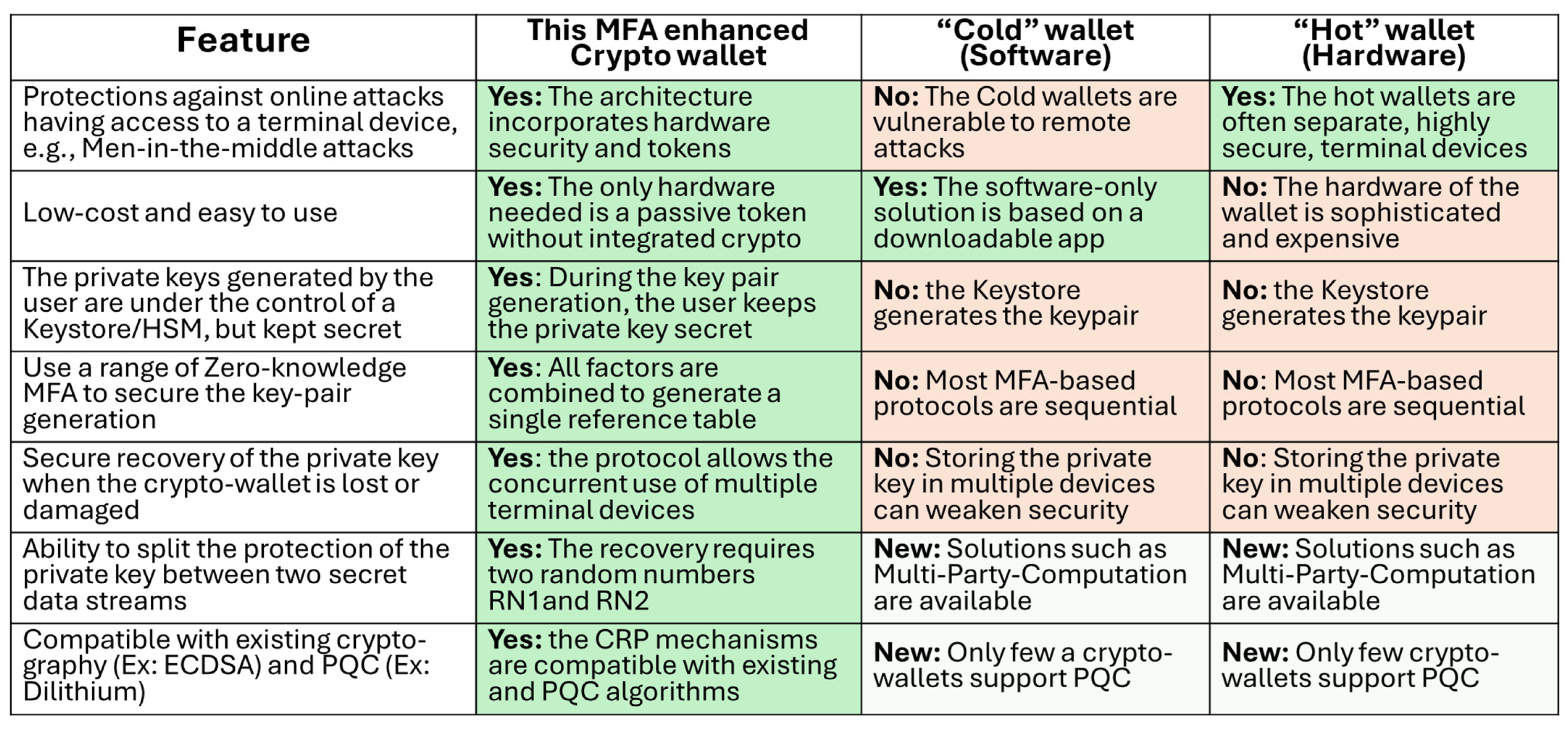
5.6. Comparative Analysis—Crypto Wallets

Figure 15 summarizes the impact of the proposed technology compared with other solutions available on the market, or under development. To capture the broad range of competitive efforts in this field, we have combined them into two categories, the “cold” wallets that are usually apps downloaded to a terminal device, and the “hot” wallets that use separate hardware to store the private keys. Hot wallets are more difficult to attack; however, they can be expensive. Hot wallets can be expensive terminal devices with secure microcontrollers, touch screen displays, and power management. Our solution only uses a small passive USB-C token without a secure microcontroller, battery, and expensive display. The unique role of our tokens is to generate on-demand responses from the embedded SRAMs; the entire software and cryptographic protocols are based on the computing element of the terminal device.

6. Conclusions and Future Work

The new protocols for PKI applications such as crypto wallets leverage three successive layers of security based on the randomly chosen numbers RN1, RN2, and RN3 and the CRP mechanisms processing the MFA. The protocols open up the following features:
The enrollment process, token distribution, and recovery cycles can be managed by an independent Keystore corporation, which only has access to the first random number RN1. Both the user and the Keystore independently generate from RN1 (concatenated with a password) a combined reference table from multiple CRP mechanisms based on multiple factors of authentication.
The novel key pair generating scheme preserves the privacy of users. As the shared RN1 enables verification of the validity of the public key Pk by the Keystore, the private keys are solely generated by the user with RN2, which is never shared and erased after key generation. The method is compatible with current PKI infrastructures, and crypto wallets with NIST’s standardized PQC.
During normal operation, the MFA is directly under the control of each user, and easy to operate. To obtain their private key and sign a crypto-transaction, the user enters the password, RN1, and RN3; inserts the token into one of the terminals pre-loaded with the app; obtains an image from the camera; and retrieves the virtual token.
On demand, the Keystore corporation can transmit to the user the reference table of the token CT-T. This allows the user to retrieve the private key when the token is lost. A new virtual enrollment using a new token is recommended.
The user can use multiple devices, thereby being protected against HW failure or loss of a single crypto wallet. With current technologies, the loss of a crypto wallet is catastrophic, and private keys are lost. The flexibility does not compromise the security, as the public keys are not stored in a single crypto wallet that can be stolen and hacked.
In the experimental section, we demonstrate that an implementation with the standardized CRYSTALS Dilithium algorithm was fast and experienced extremely low error rates. The bulk of the anticipated future work resides in the need to submit the protocols to independent third parties’ security assessments.
We recognize that each factor of authentication has its own well-known vulnerabilities. For example, it is relatively easy to read the fingerprints of the SRAM PUFs used in the tokens when under the control of opponents. The user can mitigate this threat by keeping their computers stored in a safe place. Other nanomaterials such as ReRAM memories should be considered for future work because of their superior tamper resistance. An alternate path that we are considering is the use of arrays of sensors that can be integrated into a wearable device. Each sensor has fingerprints that can be exploited to generate a reference table compatible with other methods. They are more difficult to read than plain SRAM memories and can be used to monitor vital signs.
The overall vulnerabilities of biometric authentication methods are another concern. The method presented in this paper would benefit from stronger liveness tests, and methods to prevent an AI-generated video from being successfully displayed in front of the camera of the terminal devices. The one-way-ness of the CRP mechanism would benefit from mathematical schemes such as Johnson–Lindenstrauss, which randomly projects the measurements extracted from visual images into higher dimensions [67,68]. Our future work includes the investigation of such mathematical schemes, as well as the use of 3D biometric methods with photogrammetry. By enrolling the user in a multi-dimensional space, we can mitigate simplistic attacks by bringing two-dimensional information.
The suggested XORing of the reference tables generated from each factor of authentication to compute the single reference table could be replaced in future work by other methods enhancing the one-way-ness of the protocol. In the schemes presented in this paper, an opponent can find the reference table of one remaining factor, when the two other factors are uncovered, as well as the final reference table. We will study one-way combinational methods such as those using edit distancing [69]. Finally, the new protocols are agnostic on which factors of authentication are integrated. The integration of stronger factors as they become available should be possible, as long as effective CRP mechanisms can be successfully developed.

Author Contributions

Conceptualization, B.F.C.; methodology, B.F.C.; software, M.A.; validation, M.A.; formal analysis, B.F.C. and M.A.; investigation, B.F.C. and M.A.; resources, B.F.C.; data curation, B.F.C. and M.A.; writing—original draft preparation, B.F.C. and M.A.; writing—review and editing, B.F.C. and M.A.; visualization, B.F.C. and M.A.; supervision, B.F.C.; project administration, B.F.C.; funding acquisition, B.F.C. All authors have read and agreed to the published version of the manuscript.

Funding

This research received no external funding.

Institutional Review Board Statement

Not applicable.

Informed Consent Statement

Not applicable.

Data Availability Statement

The original contributions presented in the study are included in the article, further inquiries can be directed to the corresponding author.

Acknowledgments

The authors acknowledge the invaluable support given by the research team and administrative team of the cybersecurity laboratory of Northern Arizona University.

Conflicts of Interest

The authors declare no conflicts of interest.

Abbreviations

The following abbreviations are used in this manuscript:
AIArtificial Intelligence
CACertificate Authority
CRPChallenge–Response Pair
CT-TCrypto Table Token
CT-BioCrypto Table Bio
CT-VTCrypto Table Virtual Token
CT-MaskCrypto Table Mask
ECC Elliptic Curve Cryptography
FRRFalse Reject Rate
FAR False Acceptance Rate
HWHardware
HSMHardware Secure Module
KEphemeral Key
KDEKernel Density Estimation
LWELearning With Errors
MFAMulti-Factor Authentication
MSBMost Significant Bit
PKIPublic Key Infrastructure
PUFPhysical Unclonable Functions
PkPublic Key
PQCPost-Quantum Cryptography
PWPassword
RBCResponse-Based Cryptography
ReRAMResistive Random Access Memory
RSARivest, Shamir, Adleman
SRAMStatic Random Access Memory
SkSecret Key/Private Key
SMSShort Message Service

References

  1. Buchmann, J.A.; Karatsiolis, E.; Wiesmaier, A. Introduction to Public Key Infrastructures; Springer: Berlin/Heidelberg, Germany, 2013. [Google Scholar]
  2. Lozupone, V. Analyze encryption and public key infrastructure (PKI). Int. J. Inf. Manag. 2018, 38, 42–44. [Google Scholar] [CrossRef]
  3. Smailes, J.; Köhler, S.; Birnbach, S.; Strohmeier, M.; Martinovic, I. KeySpace: Public Key Infrastructure Considerations in Interplanetary Networks. arXiv 2024, arXiv:2408.10963v3. [Google Scholar] [CrossRef]
  4. El-Hajj, M.; Beune, P. Lightweight public key infrastructure for the Internet of Things: A systematic literature review. J. Ind. Inf. Integr. 2024, 41, 100670. [Google Scholar] [CrossRef]
  5. Gentry, C.B. Certificate-Based Encryption and Public Key Infrastructure. 2002. Available online: https://patents.google.com/patent/US8074073B2/en?q=(Gentry+certificate)&oq=Gentry+certificate (accessed on 5 January 2025).
  6. Alam, M.; Hoffstein, J.; Cambou, B. Privately Generated Key Pairs for Post Quantum Cryptography in a Distributed Network. Appl. Sci. 2024, 19, 8863. [Google Scholar] [CrossRef]
  7. NIST Status Report of Phase 3 of PQC Program, NISTIR.8309. Available online: https://www.nist.gov/publications/status-report-second-round-nist-post-quantum-cryptography-standardization-process (accessed on 22 July 2020).
  8. Ducas, L.; Kiltz, E.; Lepoint, T.; Lyubashevsky, V.; Schwabe, P.; Seiler, G.; Stehlé, D. CRYSTALS-Dilithium Algorithm Specifications and Supporting Documentation; Part of the Round 3 Submission Package to NIST. Available online: https://pq-crystals.org/dilithium (accessed on 19 February 2021).
  9. Fouque, P.-A.; Hoffstein, J.; Kirchner, P.; Lyubashevsky, V.; Pornin, T.; Prest, T.; Ricosset, T.; Seiler, G.; Whyte, W.; Zhang, Z. Falcon: Fast-Fourier Lattice-Based Compact Signatures over NTRU; NIST PQC Project Round 2, Documentation. Available online: https://falcon-sign.info/falcon.pdf (accessed on 1 October 2020).
  10. Casanova, A.; Faugere, J.-C.; Macario-Rat, G.; Patarin, J.; Perret, L.; Ryckeghem, J. GeMSS: A Great Multivariate Short Signature; NIST PQC Project Round 2, Documentation. Available online: https://csrc.nist.gov/CSRC/media/Presentations/gemss-round-2-presentation/images-media/gemss-perret.pdf (accessed on 3 January 2017).
  11. Peikert, C.; Pepin, Z. Algebraically Structured LWE Revisited. J. Cryptol. 2024, 37, 28. [Google Scholar] [CrossRef]
  12. Regev, O. New Lattice-Based Cryptographic Constructions. J. ACM 2004, 51, 899–942. [Google Scholar] [CrossRef]
  13. McEliece, R.J. A Public-Key Cryptosystem Based on Algebraic Coding Theory; California Institute of Technology: Pasadena, CA, USA, 1978; pp. 114–116. [Google Scholar]
  14. Biswas, B.; Sendrier, N. McEliece Cryptosystem Implementation: Theory and Practice. In Post-Quantum Cryptography; Buchmann, J., Ding, J., Eds.; PQCrypto, Lecture Notes in Computer Science; Springer: Berlin/Heidelberg, Germany, 2008; Volume 5299. [Google Scholar]
  15. Nakamoto, S. Bitcoin: A Peer-to-Peer Electronic Cash System. 2008. Available online: www.biticoin.org (accessed on 5 January 2025).
  16. Aggarwal, S.; Kumar, N. Chapter Twelve–Cryptocurrencies; Aggarwal, S., Kumar, N., Raj, P., Eds.; Advances in Computers; Elsevier: Amsterdam, The Netherlands, 2021; Volume 121, pp. 227–266. [Google Scholar] [CrossRef]
  17. Shahzad, M.; Xu, S.; Lim, W.; Hasnain, M.; Nusrat, S. Cryptocurrency awareness, acceptance, and adoption: The role of trust as a cornerstone. Humanit. Soc. Sci. Commun. 2024, 11, 4. [Google Scholar] [CrossRef]
  18. García-Monleón, F.; Erdmann, A.; Arilla, R. A value-based approach to the adoption of cryptocurrencies. J. Innov. Knowl. 2023, 8, 100342. [Google Scholar] [CrossRef]
  19. Eyal, I.; Gencer, A.E.; Sirer, E.G.; Renesse, R.V. Bitcoin-NG: A Scalable Blockchain Protocol. In Proceedings of the 13th USENIX Symposium on Networked Systems Design and Implementation (NSDI ’16), Santa Clara, CA, USA, 16–18 March 2016. [Google Scholar]
  20. Juels, A.; Rahman, F. Systems and Methods for Securing Cryptocurrency Purchases. U.S. Patent 10,846,663 B2, 24 November 2020. [Google Scholar]
  21. Fan, C.-H.; Shih, M.-C. Cryptocurrency Securing Method and Device Thereof. U.S. Patent 11,386,429 B2, 12 July 2022. [Google Scholar]
  22. Fan, C.-H.; Hsu, C.-Y.; Shih, M.-C. Cryptocurrency securing system and method. U.S. Patent 11,941,610 B2, 26 March 2024. [Google Scholar]
  23. Tripathi, G.; Ahad, M.; Casalino, G. A comprehensive review of blockchain technology: Underlying principles and historical background with future challenges. Decis. Anal. J. 2023, 9, 100344. [Google Scholar] [CrossRef]
  24. Justinia, T. Blockchain Technologies: Opportunities for Solving Real-World Problems in Healthcare and Biomedical Sciences. Acta Inform. Med. 2019, 27, 284–291. [Google Scholar] [CrossRef]
  25. Croman, K.; Decker, C.; Eyal, I.; Gencer, A.E.; Juels, A.; Kosba, A.; Miller, A. On scaling decentralized blockchains. In Financial Cryptography and Data Security; Springer: Berlin/Heidelberg, Germany, 2016. [Google Scholar]
  26. Luu, L.; Narayanan, V.; Zheng, C.; Baweja, K.; Gilbert, S.; Saxena, P. A secure sharing protocol for open blockchains. In Proceedings of the 2016 ACM SIGSAC Conference on Computer and Communications Security, Vienna, Austria, 24–28 October 2016. [Google Scholar]
  27. Dorri, A.; Kanhere, S.S.; Jurdak, R. Blockchain in internet of things: Challenges and solutions. arXiv 2016, arXiv:1608.05187. [Google Scholar]
  28. Gervais, A.; Karame, G.O.; Wüst, K.; Glykantzis, V.; Ritzdorf, H.; Capkun, S. On the security and performance of proof of work blockchains. In Proceedings of the 2016 ACM SIGSAC Conference on Computer and Communications Security, Vienna, Austria, 24–28 October 2016. [Google Scholar]
  29. Zheng, Z.; Xie, S.; Dai, H.-N.; Wang, H. Blockchain challenges and opportunities: A survey. Int. J. Web Grid Serv. 2016, 14, 352. [Google Scholar] [CrossRef]
  30. Yu, Y.; Sharma, T.; Das, S.; Wang, Y. Don’t put all your eggs in one basket: How Cryptocurrency Users Choose and Secure Their Wallets. In Proceedings of the 2024 CHI Conference on Human Factors in Computing Systems, Honolulu, HI, USA, 11–16 May 2024. [Google Scholar] [CrossRef]
  31. Barbereau, T.; Bodó, B. Beyond financial regulation of crypto-asset wallet software: In search of secondary liability. Comput. Law Secur. Rev. 2023, 49, 105829. [Google Scholar] [CrossRef]
  32. Houy, S.; Schmid, P.; Bartel, A. Security Aspects of Cryptocurrency Wallets—A Systematic Literature Review. ACM Comput. Surv. 2024, 56, 1–31. [Google Scholar] [CrossRef]
  33. Pospieszalski, M.; Odom, C. Crypto Currency Hardware Wallet. U.S. Patent 2022/0335422 A1, 20 October 2022. [Google Scholar]
  34. Wright, C.; Savanah, S. Secure Multiparty Loss Resistant Storage and Transfer of Cryptographic Keys for Blockchain Based Systems in Conjunction with a Wallet Management System. European Patent EP3259724B1, 24 March 2021. [Google Scholar]
  35. Nolan, M.; Carboni, D.; Smith, N. Contextual Authentication of an Electronic Wallet. Methods and Systems Are Provided for a Contextual Authentication of an Electronic Wallet (e-Wallet). U.S. Patent 11,386,420 B2, 12 July 2022. [Google Scholar]
  36. Abramova, S.; Böhme, R. Anatomy of a High-Profile Data Breach: Dissecting the Aftermath of a Crypto-Wallet Case. In Proceedings of the 32nd USENIX Security Symposium (USENIX Security 23), Anaheim, CA, USA, 9–11 August 2023; USENIX Association: Berkeley, CA, USA, 2023; pp. 715–732. [Google Scholar]
  37. Almadani, M.; Alotaibi, S.; Alsobhi, H.; Hussain, O.; Hussain, F. Blockchain-based multi-factor authentication: A systematic literature review. Internet Things 2023, 23, 100844. [Google Scholar] [CrossRef]
  38. Kebande, V.; Awaysheh, F.; Ikuesan, R.; Alawadi, S.; Alshehri, M. A Blockchain-Based Multi-Factor Authentication Model for a Cloud-Enabled Internet of Vehicles. Sensors 2021, 21, 6018. [Google Scholar] [CrossRef] [PubMed]
  39. Jose Diaz Rivera, J.; Muhammad, A.; Song, W.-C. Securing Digital Identity in the Zero Trust Architecture: A Blockchain Approach to Privacy-Focused Multi-Factor Authentication. IEEE Open J. Commun. Soc. 2024, 5, 2792–2814. [Google Scholar] [CrossRef]
  40. Islamov, I. Secret Material Exchange and Authentication Cryptography Operations. U.S. Patent 11,637,694 B2, 25 April 2023. [Google Scholar]
  41. Be’ery, T.; Ohayon, O.; Shlomovits, O.; Benattar, G.; Manuskin, A.; Leiba, O. System and Method of Multi-Party Computation Based Multi-Factor Authentication. U.S. Patent 2023/0299942 A1, 21 September 2023. [Google Scholar]
  42. Popp, N. Token Provisioning. 2024. Available online: https://patents.google.com/patent/US8015599B2/en?q=(Token+Provisioning)&inventor=popp&oq=Token+Provisioning++popp (accessed on 5 January 2025).
  43. Shahbazi, Z.; Byun, Y. Analysis of the Security and Reliability of Cryptocurrency Systems Using Knowledge Discovery and Machine Learning Methods. Sensors 2022, 22, 9083. [Google Scholar] [CrossRef]
  44. Fiske, M. Securing Transactions with a Blockchain Network. U.S. Patent 11,824,991 B2, 21 November 2023. [Google Scholar]
  45. Weichbroth, P.; Wereszko, K.; Anacka, H.; Kowal, J. Security of Cryptocurrencies: A View on the State-of-the-Art Research and Current Developments. Sensors 2023, 23, 3155. [Google Scholar] [CrossRef]
  46. Barthelemy, S.; Thieblemont, J. Method for Two Step Digital Signature. U.S. Patent 8,589,693, 22 October 2008. [Google Scholar]
  47. Maximov, A.; Hell, M.; Smeets, B. Methods of Proving Validity and Determining Validity, Electronic Device, Server and Computer Programs. U.S. Patent 10,511,440, 20 February 2015. [Google Scholar]
  48. Herder, C.; Srivastava, T. System and Method for Securing Personal Information via Biometric Public Key. U.S. Patent 11,343,099 B2, 24 May 2022. [Google Scholar]
  49. Yaldin, D.; Riva, B.; Navon, A.; Pachmanov, L.; Katz, J. Techniques for Securing Digital Signatures Using Multi-Party Computation. U.S. Patent 11,689,371 B2, 27 June 2023. [Google Scholar]
  50. Pala, M.; Scriber, B.; Goeringer, S. Systems and Methods for Integrating Crypto-Currency Wallet Identifiers with Digital Certificates. U.S. Patent 2019/0295069 A1, 26 September 2019. [Google Scholar]
  51. Maletsky, K.D.; Seymour, M.J.; Garner, B.P. Generating Keys Using Secure Hardware. 2015. Available online: https://patents.google.com/patent/US9118467B2/en?inventor=Maletsky&oq=Maletsky+ (accessed on 3 September 2024).
  52. Herder, C.; Yu, M.-D.; Koushanfar, F.; Devadas, S. Physical Unclonable Functions and Applications: A Tutorial. Proc. IEEE 2014, 102, 1126–1141. [Google Scholar] [CrossRef]
  53. Schrijen, G.-J.; van der Leest, V. Comparative Analysis of SRAM Memories Used as PUF Primitives. In Proceedings of the 2012 Design, Automation & Test in Europe Conference & Exhibition (DATE), Dresden, Germany, 12–16 March 2012. [Google Scholar]
  54. Liu, R.; Wu, H.; Pang, Y.; Qian, H.; Yu, S. A Highly Reliable and Tamper-Resistant RRAM PUF: Design and Experimental Validation. In Proceedings of the 2016 IEEE International Symposium on Hardware Oriented Security and Trust (HOST), McLean, VA, USA, 3–5 May 2016; Volume 100, pp. 13–18. [Google Scholar]
  55. Cambou, B.; Gowanlock, M.; Yildiz, B.; Ghanaimiandoab, D.; Lee, K.; Nelson, S.; Philabaum, C.; Stenberg, A.; Wright, J. Post Quantum Cryptographic Keys Generated with Physical Unclonable Functions. Appl. Sci. 2021, 11, 2801. [Google Scholar] [CrossRef]
  56. Aguilar Rios, M.; Alam, M.; Cambou, B. MRAM Devices to Design Ternary Addressable Physically Unclonable Functions. Electronics 2023, 12, 3308. [Google Scholar] [CrossRef]
  57. Cambou, B.; Mohammadi, M.; Philabaum, C.; Booher, D. Statistical Analysis to Optimize the Generation of Cryptographic Keys from Physical Unclonable Functions. In Advances in Intelligent Systems and Computing; Springer International Publishing: Cham, Switzerland, 2020; pp. 302–321. [Google Scholar]
  58. Nowroozi, E.; Seyedshoari, S.; Mekdad, Y.; Savas, E.; Conti, M. Cryptocurrency wallets: Assessment and security. arXiv 2023, arXiv:2303.12940. [Google Scholar]
  59. Hinkes, A. Throw away the key or the key holder? Northwestern J. Technol. Intellect. Prop. 2019, 16, 1. [Google Scholar]
  60. Maine, J.; Nguyen, X.-T. Crypto Losses; University of Maine School of Law Digital Commons, Faculty Publications: Partland, OR, USA, 2024. [Google Scholar]
  61. Mallik, A. Man-in-the-Middle-Attack: Understanding in Simple Words. Cyberspace J. Pendidik. Teknol. Inf. 2019, 2, 109. [Google Scholar] [CrossRef]
  62. Chimienti, M.; Kochanska, U.; Pinna, A. Understanding the Crypto-Asset Phenomenon, Its Risks and Measurement Issues; Published as Part of the ECB Economic Bulletin; European Central Bank: Frankfurt, Germany, 2019. [Google Scholar]
  63. Holmes, A.; Buchanan, J. A framework for live host-based Bitcoin wallet forensics and triage. Forensic Sci. Int. Digit. Investig. 2023, 44, 301486. [Google Scholar] [CrossRef]
  64. Cambou, B.; Telesca, D.; Jacinto, H.S. PUF-Protected Methods to Generate Session Keys. In Lecture Notes in Networks and Systems; Springer International Publishing: Cham, Switzerland, 2022; pp. 744–764. [Google Scholar]
  65. Rusia, M.K.; Singh, D.K. A Comprehensive Survey on Techniques to Handle Face Identity Threats: Challenges and Opportunities. Multimed. Tools Appl. 2022, 82, 1669–1748. [Google Scholar] [CrossRef]
  66. Generated Photos. Available online: https://generated.photos/ (accessed on 5 January 2025).
  67. Johnson, W.B.; Lindenstrauss, J. Extensions of Lipschitz Mappings into a Hilbert Space. Contemp. Math. 1984, 6, 189–206. [Google Scholar]
  68. Hinrichs, A.; Vybíral, J. Johnson-Lindenstrauss Lemma for Circulant Matrices. Random Struct. Algorithms 2011, 39, 391–398. [Google Scholar]
  69. Cambou, B. Multi-Factor Authentication Using a Combined Secure Pattern; Part I. U.S. Patent 9,514,292, 6 December 2016. [Google Scholar]
Figure 1. Example of enrollment cycle with multiple factors of authentication completed by a user in cooperation with a Keystore corporation. The Keystore transmits the random number RN1 and the token while the user transmits a visual image, the password, and a virtual token. Both parties independently generate the reference table CT through the CRP mechanism.
Applsci 15 03089 g001
Figure 2. Example of computation to obtain the reference table “CT” from the three reference tables generated from the token “CT-T”, the biometric image “CT-Bio”, and the virtual token “CT-VT”.
Applsci 15 03089 g002
Figure 3. Block diagram showing how the terminal device can recover the reference table “CT” from RN1 and three factors of authentication, then the ephemeral key K from RN3 and CT. In normal operations, the key K encrypts or decrypts the private key Sk.
Applsci 15 03089 g003
Figure 4. Block diagram showing the public–private key generation {Sk; Pk}. The reference table CT is been generated during the enrollment cycle. A second random number RN2 is used concurrently by the Keystore and the terminal to generate seed a and matrix A from the reference table CT. A randomly picked number generates seed b, then the secret key consisting of vectors V1 and V2, which is used to sign the message M. The rest of the protocol is the DSA from CRYSTALS Dilithium.
Applsci 15 03089 g004
Figure 5. Block diagram showing the two-step operation that retrieves the secret key Sk and signs transaction T. During Step 1, the recovery of the reference table CT with RN1 and three factors is the same as that described in Section 2.2 and Section 2.3. In Step 2, the recovery of the ephemeral key K is based on the CRP mechanism using table CT and random number RN3. The key K allows the decryption of the private key K, and the signing of transaction T.
Applsci 15 03089 g005
Figure 6. Kernel Density Estimation of “0”, “1”, and “X” for server and client reference table CT-T generated from tokenized PUF. We observe that the SRAM PUF contains more “1”s than “0”s, which is an asymmetry due to the component. This could eventually be resolved by using a different supplier of SRAM. The rate of “fuzzy” cells is at a perfect level of 28%.
Applsci 15 03089 g006
Figure 7. Example of multiple enrollment images for the same individual to generate a bio-reference table.
Applsci 15 03089 g007
Figure 8. Kernel Density Estimation of “0”, “1”, and “X” for server and client reference table CT-bio generated from facial images. The distribution of “0”s versus “1”s is almost perfect in this protocol, as well as the ratio of fuzzy positions, which is close to 1/3.
Applsci 15 03089 g008
Figure 9. Kernel Density Estimation of “0” and “1” for server and client reference table CT-VT generated from virtual tokens. The 50-50% distribution is perfect, and none of the positions are fuzzy.
Applsci 15 03089 g009
Figure 10. Seed error distribution by fragmentation level, showing little to no impact of the fragmentation process. In this analysis, we want to verify that the error rates are well distributed within the cryptographic keys, and that the key fragmentation process is not negatively impacted by a poor distribution of the erratic bits.
Applsci 15 03089 g010
Figure 11. Diversity based on gender, age, and ethnicity.
Applsci 15 03089 g011
Figure 12. Kernel Density Estimation of “0”, “1”, and “X” for server and client reference/crypto table generated from token, bio, and virtual token table generating the combined reference table CT. The high rate of “1”s observed with tokens (see Figure 6) is no longer an important factor.
Applsci 15 03089 g012
Figure 13. RBC time vs. key error for different fragmentation levels. This graph shows that a fragmentation of 8 is an excellent tradeoff. The recovery times stay well below one second in the range of interest.
Applsci 15 03089 g013
Figure 14. Average latency for key operations. The two longest operations are the generation of the reference table CT-Bio from the server during the enrollment cycle, as well as the generation of the reference table CT-Token from the client device during normal operation. All error correcting and cryptographic schemes are below one second.
Applsci 15 03089 g014
Figure 15. Comparative analysis of a crypto wallet using the suggested technology against both competitive “Cold” and “Hot” crypto wallet solutions.
Applsci 15 03089 g015
Table 1. FRR and FAR verification percentages for different fragmentation levels. With higher fragmentation levels, the protocol can handle higher rates of errors. Therefore, the false rejection rate decreases with higher fragmentation, while the false acceptance rate moves in the opposite direction.
Test TypeFragmentationTrue (%)False (%)
FRR (False Reject Rate)177.6722.33
296.703.30
499.240.76
81000
161000
FAR (False Acceptance Rate)10100
20.2599.75
41.0198.98
87.8992.13
1621.8878.12
Table 2. Verification percentage based on gender, age, and skin tone. The observed variations are not statistically significant and are well within the expected range.
GenderAge RangeSkin ToneTrue (%)False (%)
Female20–34
  • Yellow Level −10
94.285.72
  • Dark Brown Level +15
98.331.67
  • Black Level +25 Yellow Level −15
93.336.67
  • Yellow Level +20
946
  • Light Brown Level +10
95.384.62
35–50
  • Yellow Level −10
1000
  • Dark Brown Level +15
91.678.33
  • Black Level +25 Yellow Level −15
955
  • Yellow Level +20
95.714.29
  • Light Brown Level +10
94.555.45
51–65
  • Yellow Level −10
955
  • Dark Brown Level +15
92.227.78
  • Black Level +25 Yellow Level −15
91.788.22
  • Yellow Level +20
9010
  • Light Brown Level +10
98.571.43
Male20–34
  • Yellow Level −10
93.336.67
  • Dark Brown Level +15
95.384.62
  • Black Level +25 Yellow Level −15
98.611.39
  • Yellow Level +20
96.673.33
  • Light Brown Level +10
964
35–50
  • Yellow Level −10
955
  • Dark Brown Level +15
89.2310.77
  • Black Level +25 Yellow Level −15
96.373.64
  • Yellow Level +20
96.673.33
  • Light Brown Level +10
928
51–65
  • Yellow Level −10
973
  • Dark Brown Level +15
98.181.82
  • Black Level +25 Yellow Level −15
1000
  • Yellow Level +20
89.3310.67
  • Light Brown Level +10
94.555.45
Disclaimer/Publisher’s Note: The statements, opinions and data contained in all publications are solely those of the individual author(s) and contributor(s) and not of MDPI and/or the editor(s). MDPI and/or the editor(s) disclaim responsibility for any injury to people or property resulting from any ideas, methods, instructions or products referred to in the content.

