Article

Stability Analysis of Isolated Roof in Overlapping Goaf Based on Strength Reduction

1
College of Resources and Environmental Engineering, Jiangxi University of Science and Technology, Ganzhou 341000, China
2
Jiangxi Provincial Key Laboratory of Low-Carbon Processing and Utilization of Strategic Metal Mineral Resources, Ganzhou 341000, China
3
Jiangxi Provincial Key Laboratory of Safe and Efficient Mining of Rare Metal Resources, Ganzhou 341000, China
4
Changsha Institute of Mining Research Co., Ltd., Changsha 410012, China
*
Author to whom correspondence should be addressed.
Appl. Sci. 2025, 15(6), 3067; https://doi.org/10.3390/app15063067
Submission received: 16 January 2025 / Revised: 4 March 2025 / Accepted: 5 March 2025 / Published: 12 March 2025
(This article belongs to the Special Issue Novel Research on Rock Mechanics and Geotechnical Engineering)

Abstract

:
An isolated roof is an indispensable component of overlapping goaf. Focusing on the influence of dislocated width and width ratio on the stability of the isolated roof, this study analyzes the change rule of the safety factor of the roof supported by misaligned pillars and reveals the evolution characteristics of it by integrating numerical simulation into the strength reduction method. Firstly, with the increase of the dislocated width, the safety factor experienced three stages of sharp decrease, change from decrease to increase, and rapid increase. Secondly, the width ratio λ = 2 can be determined as the critical value of the safety reserve of the roof. In the interval λ ˂ 2, F decreases sharply with the increase of λ, but when λ ˃ 2, F decreases slowly and tends to 0. Thirdly, the overlap rate of pillars is a determinant of the type of damage but not of the safety factor of the roof. When η = 0, the safety factor is independent of the overlap rate. Furthermore, increasing the dislocated width can make the failure units accumulate continuously and then promote the plastic zone to expand gradually, resulting in roof collapse due to the penetration of the failure units. In this process, the tensile failure zone evolves from a single fold line to a wavy line, and the shear failure zone changes from a diagonal strip to a square strip. The study provides a new method to improve the stability of the roof, which is helpful to significantly reduce the collapse risk of overlapping goaf.

1. Introduction

The goaf formed by ore mining is a major potential hazard, which seriously threatens the safety of mine production [1,2,3]. During the mining process, two or more layers of goaf are formed at different spatial heights, which is called overlapping goaf. The support system of overlapping goaf is composed of upper pillars, isolated roof, and lower pillars. Among them, the isolated roof is located between the upper and lower pillars, which is the weak part of the whole support system and the key to maintaining the stability of overlapping goaf [4].
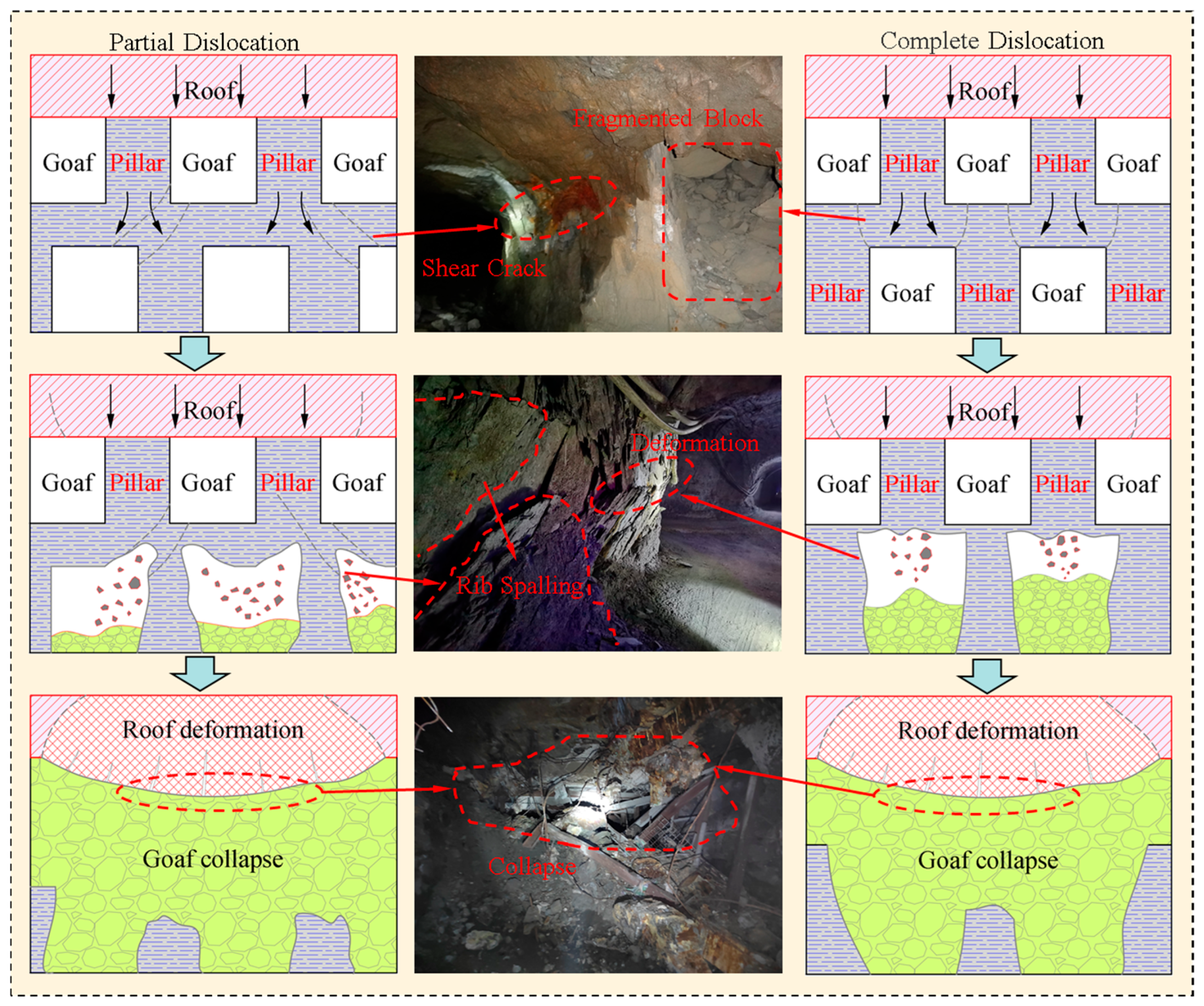
The stability of the roof is closely related to the relative position of the upper and lower pillars. From the point of view of the force relationship, the relative positions of the upper and lower pillars can be divided into three cases: full alignment, partial alignment, and misalignment (Figure 1). In the first case, the upper and lower pillars are perfectly aligned, and the pressure from the overlying strata is directly transmitted to the lower pillars through the upper pillars. In this case, the roof of the partition is almost unloaded, and naturally, the role of the roof of the partition in the support system is almost negligible. In the second case, in the downward transmission process of the overlying pressure, part of the pressure is transferred directly from the upper pillar to the lower pillar, and the other acts on the roof of the isolated roof, causing the roof to bear part of the load. In other words, the isolated roof shares part of the pressure in the support system. In the third case, the upper and lower pillars are completely misaligned, and the pressure of the overlying strata can only be transferred to the lower pillars through the isolated roof. The roof bears the largest load comparatively, and therefore, instability and collapse are most likely to occur.
Regarding the stability of overlapping goaf, scholars have carried out relevant research on the instability prediction of isolated roof with pillar overlap rate as variable [5,6,7,8,9,10,11,12,13,14]. These studies mainly focus on the changes in the stability state of the isolated roof during the process, as shown in Figure 1a–c, when the overlap rate of the top and bottom pillars decreases from 100% to 0% [15,16,17]. However, it can be seen from Figure 1 that the overlap rate cannot truly reflect the relative position relationship between the upper and lower pillars. In fact, when the pillar overlap rate is 0%, it is not only the state shown in Figure 1c. Theoretically, as long as the lower pillar is located at any position below the upper goaf, the overlap rate of the pillar is 0% (Figure 2). Obviously, the different relative positions of pillars will inevitably lead to different stress for the isolated roof, and the stability of the roof will inevitably change as well.
In Figure 3, c is the length between the center lines of the upper and lower pillars, a is the span of the goaf, and b is the width of the pillars, h is the thickness of the isolated roof. When c is 0, the lower pillar is completely aligned without dislocation. with the increase of c, the lower pillar moves to the middle of the goaf. When c = (a + b)/2, the lower pillar is located in the middle of the upper goaf. If c is further increased, the lower pillar moves to the right side of the upper goaf. Therefore, as long as c meets bca, the overlap rate of the pillars is 0%. However, in the process of c changing from b to a, the stress of the roof must also change because the relative positions of the pillars in the upper and lower layers have changed. Obviously, when the upper and lower pillars are not aligned, the stability state of the roof is not invariable. Focusing on the influence of misaligned support and pillar size on the stability of the isolated roof, this study established a stability analysis method for the roof based on strength reduction. Then, the variation law of the safety factor of the roof under misaligned pillar support was analyzed, revealing the evolution characteristics of instability under different misalignment distances and pillar sizes. This study provides a quantitative method for evaluating the stability of the isolated roof, and the research results can be widely applied to the design of multi-level mining and the stability analysis of multi-layer goaf, which can significantly reduce the risk of collapse in overlapping goaf areas.

2. Strength Reduction Method for Stability Analysis of an Isolated Roof

2.1. Calculation Process of the Strength Reduction Method

The basic principle of the strength reduction method is to divide the strength of the rock mass by a certain reduction coefficient to obtain new material parameters and use them for mechanical calculation [18,19,20]. Then, the strength of the rock mass is continuously reduced until it is in a critical instability state. Therefore, the reduction factor at critical instability is calculated, which is the safety factor.
By defining the cohesion of a rock mass as c0, friction as φ0, and the reduction coefficient as Fs, the shear strength reduction formula is as follows:
c = c 0 F s
φ = arctan tan φ 0 F s
With reference to the shear strength reduction method, the formula of tensile strength reduction is proposed:
σ t = σ 0 F t
In Equation (3), σ0 is the tensile strength, Ft is the reduction factor, and σt is the reduced tensile strength.
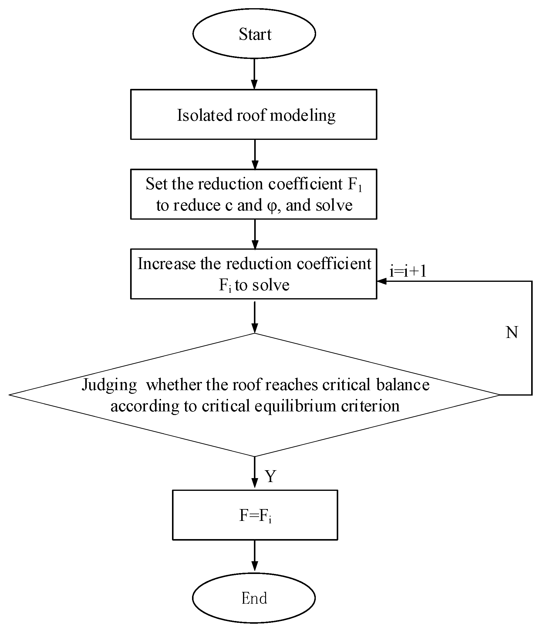
It is not difficult to find that the key to the stability analysis of the strength reduction method of the isolated roof is how to accurately calculate the safety factor. This problem can be solved by combining the strength reduction method with numerical simulation. Taking shear strength reduction as an example, the calculation process is as follows:
(1)
Establish a model of the overlapping goaf, including the upper pillar, the isolated roof, and the lower pillar;
(2)
Calculate the model by using the initial parameters c0 and φ0 of the model until the calculation converges;
(3)
Continuously reduce the cohesion and friction until critical equilibrium is reached;
(4)
Using Equations (1) and (2), the safety coefficient Fs of the isolated roof is obtained;
(5)
Change the relative position of the upper and lower pillars, and calculate the safety factor of the roof by the above steps (1)~(4).
The above steps are shown in Figure 4.
From the analysis of the above calculation process, it can be concluded that strength is the main factor affecting the safety factor of the isolated roof. All other conditions being equal, the higher the strength, the greater the safety factor, and the more stable the roof.

2.2. Calculation Model and Scheme

The spatial relationship between the upper and lower gob is very complicated due to the large differences in the form of the goaf, which causes great obstacles to the study of the goaf. For this reason, scholars have mostly simplified the shape of the goaf reasonably and used the beam model or plate model to study the stability of the goaf [21,22,23,24]. In this paper, taking the regular cuboid overlapping goaf as the object, the strength reduction method is deeply coupled with numerical simulation to calculate the safety factor of the isolated roof in the overlapping goaf and further analyzes the evolution characteristics of the stability state of the roof under the condition of dislocation support.
A mine in Hunan Province used open-stope mining initially, and after a long time of mining, several overlapping goafs formed. The goaf is 20–40 m wide and supported by pillars with a width of 8–10 m. There is a 10 m isolated roof between the upper and lower goaf to ensure mining safety. This research takes the goaf of the mine as the background, and a three-dimensional numerical calculation model is established, in which the width of the mining airspace is 40 m, the height is 40 m, the width of the pillar is 10 m, and the thickness of the isolated roof is 10 m, as shown in Figure 5. As can be seen, the upper and lower pillars are completely aligned, in this case, c = 0. Considering the different position relationship between the pillars, a model is established for every 2 m increase of the c, and thus a series of models are established for simulation calculation. Accordingly, the calculation scheme starts from c = 0, and each additional 2 m is a scheme, making a total of 21 schemes. Furthermore, the boundary conditions of the model are set as follows: the bottom is fixed, the lateral movement is restricted by the side, and the uniform load is applied at the top. The mechanical parameters required for simulation calculation are derived from experiments, as shown in Table 1.

3. Stability Analysis of Isolated Roof Under the Staggered Support

3.1. Relationship Between the Safety Factor and the Relative Position of the Pillars

The relative positions of the upper and lower pillars in the overlapping goaf are random rather than fixed, but the distance between the center lines of the upper and lower pillars will not exceed the width of goaf no matter how it changes. To illustrate the problem, the concept of dislocated width is introduced, and it is defined as the distance between the center lines of the upper and lower pillars, which is c in Figure 3. It is not difficult to determine from the figure that when the upper and lower pillars are perfectly aligned, the dislocated width is the smallest, and cmin = 0. When the lower pillar moves to the position directly below the adjacent upper pillar, the dislocated width is the largest, and cmax = a + b; in this case, the upper and lower pillars are also completely overlapped.
The calculation results of each scheme and the safety factor curve are shown in Figure 6. The safety factor of the isolated roof is closely related to the dislocated width, and the curve shows a clear trend from falling to rising, which looks like a parabola with an upward opening and has remarkable symmetry. Analysis of the curve shows that with the increase of c, the curve can be roughly divided into three stages with c = 12 and c = 28 as the separatrix:
(1)
The first stage (L1) is the rapid decline of the safety factor. The safety factor of the isolated roof decreases rapidly with the increase of the dislocated width, and the safety factor decreases almost in a steep straight line during this stage. The upper and lower pillars are gradually misaligned from complete alignment, which causes the pressure from the overlying strata to transfer from the upper pillar to the isolated roof and then to the lower pillar. The roof begins to bear part of the load, and its safety reserve drops sharply from large to small.
(2)
The second stage is the L2 where the safety factor changes from down to up. When the dislocated width continues to increase, the safety factor no longer shows the rapid decline in the L1 stage but instead enters the interval from decline to rise. In this interval, the curve first slowly drops and reaches the bottom when the dislocated width is 20 m and then begins to enter the rising period. During this stage, although the variation range of the safety factor is not significant, its value is less than 1.5. Obviously, the continuous low movement of the safety factor may threaten the stability of the roof and even easily lead to roof collapse.
(3)
The third stage (L3) is the rapid increase of the safety factor. Due to the symmetry of the upper and lower pillars, if the dislocated width continues to increase, the spacing between the upper and lower pillars will be reduced, which is equivalent to the pillars moving towards each other. The load transfer is basically the same as that in the first stage, mainly between the upper and lower pillars, the stress on the roof is greatly reduced, and the safety factor is rapidly increased.
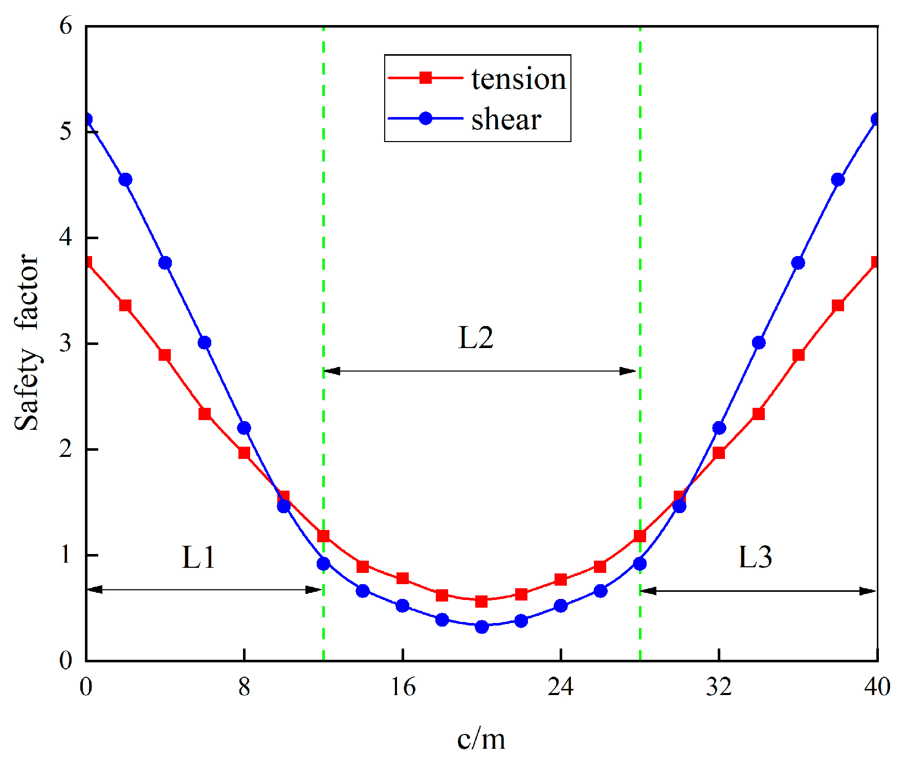
Figure 6. Relationship between the safety factor of the roof and the dislocated width.
Applsci 15 03067 g006

3.2. The Relationship Between the Failure Type of the Isolated Roof and the Overlap Rate of the Pillars

Damage to the rock mass is closely related to its load and strength. When the stress on the isolated roof exceeds its own strength, the roof will be damaged. Obviously, the tensile failure of the roof is due to its strength being less than the tensile, while the shear failure of the roof is due to its strength being less than the shear. This study introduces the safety factor to characterize the ease of failure of the roof. The low tensile safety factor of the roof indicates that it is prone to tensile failure, while the low shear safety factor is more likely to result in shear failure. Therefore, the two safety factors correspond to two different types of damage. In the numerical simulation results, the failure types of the roof can be divided into tensile failure and shear failure, which can be reflected in the safety factor curve as the tensile failure zone and shear failure zone (Figure 7). It is easy to deduce from the above analysis that the tensile safety factor of the former is less than the shear safety factor, while the shear safety factor of the latter is less than the tensile safety factor.
The overlap rate of the pillars determines the failure type of the isolated roof. In the first case, when the overlap rate is η > 0, the upper and lower pillars overlap at least partially, and the load is mainly transferred through the upper and lower pillars, so that the shear mainly acts on the pillars rather than the roof. However, there is still a risk of tensile failure in the area of tensile stress concentration in the middle of the roof. In the other case, when the overlap rate is η = 0, the upper and lower pillars are completely misaligned, and the load from the overlying strata cannot be effectively transferred through the pillars. In this case, as the connecting structure, the roof is the transition carrier bearing all the load. And both the pressure of the upper pillar and the supporting reaction of the lower pillar act on the isolated roof, forming a shear effect, resulting in a significant reduction of the shear safety factor of the roof, and relatively, the roof is more prone to shear failure.

3.3. The Safety Factor of the Isolated Roof When the Overlap Rate Is 0

Generally speaking, most studies believe that the overlap rate of the pillars has a direct impact on the stability of the roof. The smaller the overlap rate, the greater the possibility of the roof collapse. However, from the research that has been carried out, there is a misunderstanding about the stability of the roof when the overlap rate is η = 0. Among them, the most prominent problem is that most studies believe that when the overlap rate is η = 0, the stability state of the roof remains constant, that is, as long as the overlap rate is η = 0, the tensile stress or shear stress of the roof will be a fixed value and will not change inevitably.
But the fact is that the relative position of the upper and lower pillars determines whether the isolated roof is stable. As long as the lower pillar moves between the adjacent upper pillars, the overlap rate of the pillar is 0. In other words, even if the overlap rate is 0, the relative positions of the upper and lower pillars may be different. Therefore, it is not accurate to evaluate the stability of the roof by simply using the overlap rate. In Figure 7, when the overlap rate η is reduced from 1 to 0, the safety factor continues to decline, which is basically consistent with other research results. However, it should be noted that when the overlap rate is η = 0, the safety factor of the roof of the partition is still changing, which is significantly different from other research results. In Figure 7a, the variation range of tensile factor is 1.61~3.96, and the variation range of shear factor is 1.29~3.98. In Figure 7b, the variation range of the tensile factor is 0.56~1.55, and that of the shear factor is 0.32~1.46. In Figure 7c, the variation range of the tensile factor is 0.30~0.95, and the variation range of the shear factor is 0.09~0.94. This series of data all show that as long as the dislocated width changes, regardless of whether the overlap rate η changes, the safety factor will change.
Furthermore, the safety factor is used to evaluate the stability of the roof when the overlap rate is 0. According to the principle of the most unfavorable value, the minimum value of the tensile factor and shear factor is taken as the safety factor of the roof. Referring to relevant research, a safety factor of 1.5 is taken as the critical point. If the safety factor is less than 1.5, the roof is judged to be unstable, otherwise it is stable. According to the above methods, the stability state of the roof shown in Figure 7a,c was evaluated, and the results are shown in Table 2. It can be seen that when the overlap rate is η = 0; due to the change in the dislocated width, the safety factor will also change, which causes the change in the stability state of the isolated roof.

4. Effect of Width Ratio and Dislocated Width on the Stability of the Isolated Roof

4.1. Characterization of the Variation in the Safety Factor for Different Width Ratios

In order to deeply explore the change characteristics of the safety factor of the isolated roof in different sizes of excavation space, the concept of the width ratio is proposed. The ratio of the goaf width to the pillar width is defined as the width ratio, which is used to analyze the stability of the roof.
λ = a b
In the equation, λ is the width ratio, which is a parameter indicating the size of the goaf; a and b are the width of the goaf and the width of the pillar, respectively.
The numerical calculation results are extracted to draw the curve diagram of the relationship between the safety factor and the width ratio, as shown in Figure 8. The safety factor F of the isolated roof has a significant stage change characteristic, with λ = 2 as the dividing line, the safety factor curve can be divided into the safety reserve decreasing stage A and the safety reserve stabilizing stage B. When λ ˂ 2, F is larger in general, and the roof has sufficient safety reserve. However, F decreases sharply with the increase of λ, as shown in the following: the tensile safety factor Ft decreases from 13.28 to 2.72, and the shear safety factor Fs decreases from 7.78 to 1.82. On the contrary, when λ ˃ 2, F is smaller in general, and the curve becomes very smooth, and within this stage, the increase of λ only makes F decrease slowly and tend to 0. Therefore, it is very clear that the width ratio λ is an important factor affecting the stability of the roof in the overlapping goaf.
According to Equation (3), λ is jointly determined by the width of the goaf and the width of the pillar, and its essence is a characteristic parameter indicating the size of the overlapping goaf. The greater λ means that the goaf is relatively larger, or the pillar is relatively smaller. But in either case, the isolated roof is bound to bear greater loads. On the other hand, the strength of the roof does not change due to λ. Therefore, the increased load naturally causes a decrease in the safety factor F, which further leads to the evolution of the roof from stability to instability. This is the basic law of the influence of λ on the stability of the roof. Obviously, a reasonable width ratio is crucial to guarantee the stability of the roof. The smaller λ is, the larger F is, and the better the stability of the roof is. From Figure 7, it is not difficult to determine that when λ ˂ 2, F is greater than 1.5, and when λ ˃ 2, F tends to 0. Accordingly, in order to make the roof be in a stable state, the width ratio should not be greater than 2.

4.2. Characteristics of the Destabilization Evolution of the Isolated Roof Under Different Dislocated Widths

The plastic zone is the most direct reflection of rock mass failure. Extracting numerical simulation calculation results and analyzing the changes in the plastic zone of the isolated roof (Figure 9 and Figure 10) with dislocated width, the following characteristics were found:
(1)
The distribution of the plastic zone of the isolated roof is closely related to the dislocated width, and it has extremely significant symmetry. The smaller the dislocated width, the more obvious the bearing characteristics of the pillar, and the more sparse the failure units in the roof of the interlayer. On the contrary, the greater the dislocated width, the more obvious the bearing characteristics of the roof, and the denser the failure units. In addition, the distribution of the plastic zone shows very clear characteristics. If the center line of the upper and lower pillars is set as the axis, the failure units are concentrated on both sides of the axis and basically symmetrically distributed.
(2)
When the upper and lower ore pillars are completely aligned, the strength of the roof is continuously reduced until it is damaged, then it can be found that the roof has tensile damage in the process of reduction, and the plastic zone is shaped like an I-beam. This phenomenon of course has a reasonable explanation: when the dislocated width is 0, the upper and lower pillars can be regarded as a whole structure, and the pressure from the overlying strata can be smoothly transmitted to the floor through this whole structure. The roof is not subjected to shear, so there are few shear failure units in the roof. However, due to its own gravity, when the tensile strength is constantly reduced, a large number of tensile damage units will eventually be generated, resulting in damage to the roof.
(3)
When the upper and lower pillars are misaligned, the pressure from the overlying strata must be transmitted downwards through the partition roof, which plays a “connecting link” role in the support system. At this point, the top plate of the interlayer is subjected to both tensile stress and shear, resulting in tensile and shear zones. But the two occur at different locations, with tensile failure mainly occurring in the opposite area where the interlayer roof contacts the pillars, and shear failure mainly occurring in the area between the upper and lower pillars.
(4)
The evolution of the failure scope and the failure form of the isolated roof show different laws respectively. The evolution law of the failure scope is that the plastic zone is initially born around the pillar, and with the increase of the dislocation, the failure unit gradually expands outwards and finally penetrates through the roof. Furthermore, the evolution of plastic zone morphology is as follows: the initial failure zone is limited to the periphery of the pillar, the tensile zone is like a folded line, and the shear zone is a diagonal strip. With the increase of the dislocation, the damage units continue to gather, and the plastic zone begins to expand outward, which leads to the continuous expansion of the boundaries of the plastic zone. Ultimately, the tensile zone evolves from a single folded line into a large wave, and the shear zone, which looks like a diagonal strip, evolves into a square strip.
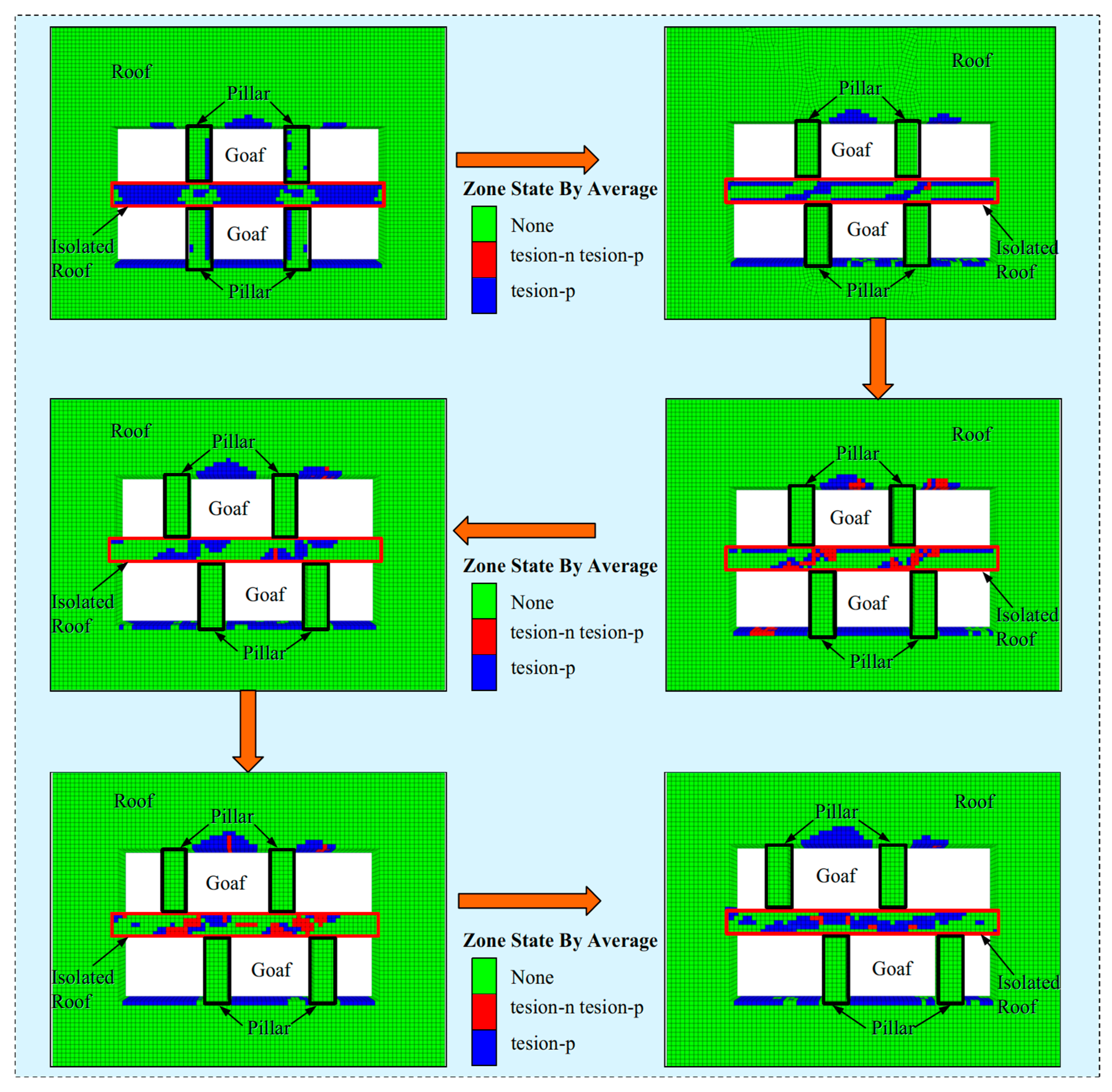
Figure 9. Evolution of failure units in the roof with increasing dislocated width by reducing tensile strength.
Applsci 15 03067 g009
Figure 10. Evolution of failure units in the roof with increasing dislocated width by reducing shear strength.
Applsci 15 03067 g010

5. Discussion

5.1. Criteria for Judging the Critical Equilibrium State of the Isolated Roof

The key to analyzing the stability of the isolated roof using the strength reduction method lies in how to determine the critical equilibrium state. From related research of geotechnical mechanics, the criteria for determining the instability of the rock mass can be divided into three categories: plastic zone penetration criteria, critical point displacement mutation criteria, and calculation non-convergence criteria. These three standards have different judgments on the critical equilibrium state of the rock mass.
The plastic zone penetration criterion considers that when the plastic zone penetrates through the rock mass, it can be judged that the rock mass has entered the critical equilibrium state [25,26,27,28,29]. The critical point displacement criterion is to determine the point of displacement mutation by monitoring the displacement change at the critical point, which is regarded as the critical equilibrium point of the rock mass stability state. The judgment method of the non-convergence criterion is more direct. By continuously reducing the strength of the rock mass until the numerical calculation does not converge, the non-convergence state is determined as the critical equilibrium state.
Each of the above three criteria has its own focus, and the plastic zone penetration criterion is the most clear explanation for rock mass instability, which is the criterion used in this study. However, it is not clear whether the critical point displacement criterion and the non-convergence criterion are applicable to the strength reduction analysis of the isolated roof. For this reason, it is necessary to discuss the applicability of different criteria separately.
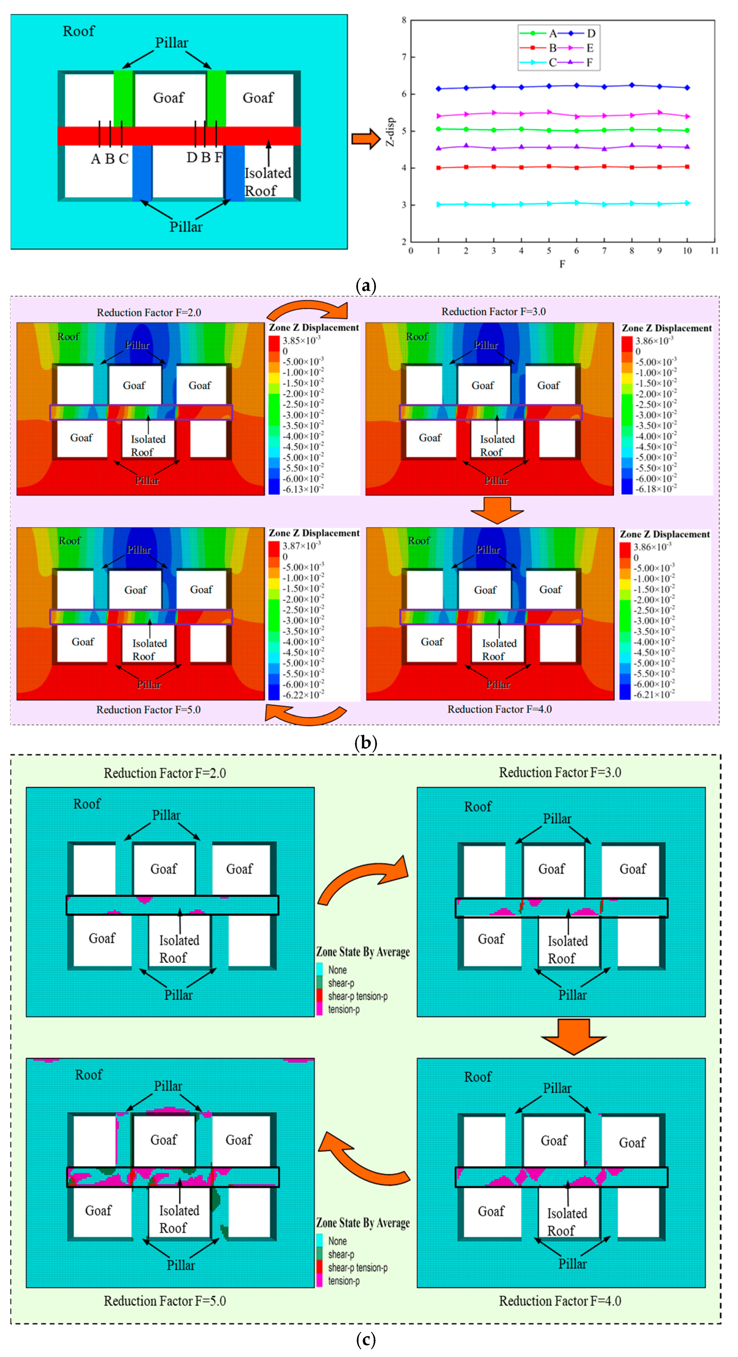
During the numerical calculation process, six monitoring lines A, B, C, D, E, and F were set up to monitor the displacement changes in key areas of the isolated roof, as shown in Figure 11a. The calculation results indicate that the displacement change of the roof is stable, without significant fluctuations, and there are no sudden changes. Taking monitoring line F as an example, regardless of how the strength is reduced, the displacement remains around 61.5 mm. Therefore, the displacement curve is basically a horizontal straight line, and the displacement cloud diagrams with different reduction factors are also roughly the same (Figure 11b).
It should be noted that the lack of significant change in displacement does not mean that the rock mass is in a stable state [30,31,32]. Due to the continuous reduction of strength, the roof continues to weaken its ability to resist damage, leading to its stability deterioration, which is evidenced by the distribution of the plastic zone (Figure 11c); the range of the plastic zone continues to expand in the process of the increase of the strength reduction factor. According to the plastic zone penetration criterion, when the reduction factor increases to 4.0, the roof has already been damaged, and it has experienced the critical equilibrium state before that. However, since the displacement has never undergone a sudden change, the critical point displacement criterion considers that the roof has still not reached critical equilibrium. Obviously, the critical point displacement criterion is not applicable to the analysis of the stability strength reduction method of the roof.
In numerical simulation analysis, the phenomenon of non-convergence of the calculation process is often regarded as a distinctive feature of the rock mass in critical equilibrium [33]. In this study, it was found that no matter what the dislocation of the upper and lower pillars is, non-convergence occurs when the destruction rate of the units reaches 80% to 85%. Such a high destruction rate makes most of the units become plastic units, and the roof has been penetrated by the plastic zone.
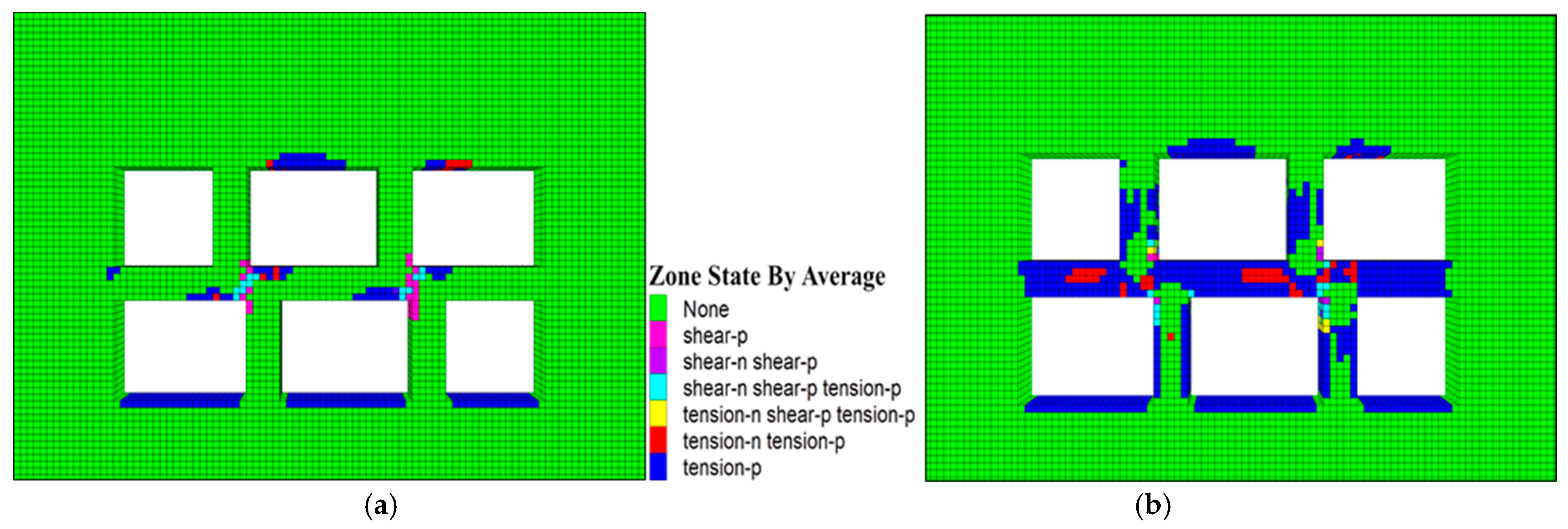
Figure 11c shows the evolution of the plastic zone of the roof. When the reduction factor is increased to 4.0, the failure rate of units is only 21.3%, but the roof has been penetrated by the plastic zone, which is the critical equilibrium state identified by the plastic zone penetration criterion, but far from reaching the calculation of the non-convergence criterion. If the strength continues to be reduced, the calculation process will not converge until the failure rate reaches 84.3% (Figure 12). At this point, the roof has been covered with failure units, and the roof must have been damaged, rather than being considered to be in critical equilibrium (Figure 13). Therefore, the non-convergence criterion is also not suitable for determining the critical equilibrium state.
Based on the above analysis, the plastic zone penetration criterion is relatively objective and accurate in determining the critical equilibrium state of the roof. Nevertheless, for the numerical simulation study of rock mechanics, scholars still have different understanding of the critical equilibrium state, and it is still controversial whether the criterion of plastic zone penetration is the best criterion. From the perspective of numerical simulation analysis, the plastic zone refers to the area where the rock mass undergoes irreversible deformation after being subjected to forces exceeding its strength limit. The larger the plastic zone, the more significant the rock mass failure. But this is not enough to directly indicate that when the plastic zone penetrates the roof, it is in a critical equilibrium state. In fact, when the plastic zone extends to a specific range, the roof may shift from a stable state to instability. So far, there is still no clear understanding of the extent of this plastic zone and the relationship between the plastic zone and the failure of the interlayer roof. To address this issue, further research will be carried out in order to propose a more appropriate criterion.

5.2. The Complexity of Overlapping Goafs

It should be noted that all the above analyses are based on the simplified regular goaf. In the established model, the pillar and the roof in the overlapping goaf are regular rectangles, which is a relatively simple morphology. Unlike this, the morphology of the actual goaf is very complex [34], and the pillar and the roof are not simple rectangles (Figure 14), which is a big difference between the simplified model. Therefore, the simulation analysis using the simplified model cannot accurately reflect the complexity of the overlapping goaf.
In addition, there are a series of distortion points in the safety factor curves of the roof supported by shaped pillars, and it is not known how these distortion points are related to the shape of the pillars. The Figure 13 illustrates the relationship between the dislocated width and the safety factor of the roof supported by hourglass and funnel pillars. For the hourglass pillar-supported roof, the safety coefficient curve produces a distortion zone on each flank of the valley, and for the funnel pillar-supported roof, the safety factor curve produces a distortion zone on the valley, which is significantly different from that of the roof supported by regular-shaped pillars. The questions of how such a distortion zone is generated, whether there is a relationship between it and the shape of the pillars, and how to establish such a relationship by mathematical modeling have not been well solved so far. As a next step, more in-depth studies will be carried out with a view to finding out the answers to these questions.

6. Conclusions

(1)
It is proposed to adopt the dislocated width to express the relative position relationship between the upper and lower pillars. The study shows that the increase of the dislocated width will lead to the continuous change of the safety factor of the isolated roof. The curve of the safety factor can be divided into three stages: the sharp decline stage, the decline-to-increase stage and the rapid increase stage. In the first stage, the safety factor is inversely correlated with the dislocated width, and the safety reserve drops sharply; In the second stage, the safety factor changes only slightly, and the curve firstly decreases slowly to the inflection point, and then turns to rise, and the stability of the roof is the worst; In the third stage, the safety factor is positively correlated with the dislocated width, and the increase of the dislocated width makes the safety factor rise rapidly, which leads to the obvious enhancement of the stability of the roof.
(2)
The overlap rate of pillars determines the type of failure of the roof but not the decisive factor of the safety factor. When the overlap rate is η > 0, the tensile safety factor is less than the shear safety factor, which leads to the tensile failure of the roof more easily. The greater the value, the greater the safety factor of the roof. However, when the overlap rate is η = 0, the shear safety factor is less than the tensile safety factor, resulting in the roof being more prone to shear failure. During this stage, the safety factor changes with the change in the dislocated width but is not related to the overlap rate.
(3)
The width ratio is the key factor affecting the stability of the roof. It is found that the width ratio λ = 2 can be the critical value of the safety reserve. When λ ˂ 2, the safety factor F of the roof is large, and the safety reserve is sufficient, but F decreases sharply with the increase of λ in this stage. On the contrary, when λ ˃ 2, with the increase of the width ratio λ, F slowly decreases and gradually tends to 0. Accordingly, reducing the width ratio helps to improve the stability of the roof, and in order to prevent it from destabilizing, the width ratio should not be larger than 2.
(4)
The study reveals the evolution of the plastic zone of the roof. The failure units are concentrated and symmetrically distributed on both sides of the center line of the upper and lower pillars. The plastic zone is born around the pillar at the beginning, where the tensile failure zone is like a fold line, and the shear failure zone is an oblique strip. With the increase of the dislocated width, resulting in the accumulation of failure units, which promotes the acceleration of the expansion of the plastic zone. Gradually, the tensile failure zone changes into a wavy line, and the width of the shear failure zone becomes a square strip.

Author Contributions

Writing—original draft preparation, C.L.; writing—review and editing, K.Z.; methodology, P.Z.; investigation, C.G. All authors have read and agreed to the published version of the manuscript.

Funding

This work was supported by the National Key Research and Development Program of China (No. 2017YFC0804601) and the National Natural Science Foundation of China (No. 51664018).

Institutional Review Board Statement

Not applicable.

Informed Consent Statement

Not applicable.

Data Availability Statement

The original contributions presented in this study are included in the article. Further inquiries can be directed to the corresponding author.

Acknowledgments

The authors are very grateful for the financial contributions and convey their appreciation to the organizations for supporting this basic research.

Conflicts of Interest

Author Chang Liu was employed by the company Changsha Institute of Mining Research Co., Ltd. The remaining authors declare that the research was conducted in the absence of any commercial or financial relationships that could be construed as a potential conflict of interest.

References

  1. Shang, Z.; Tang, S.; Jiao, W.; Liu, C. Failure Probability of Goaf in Large-Scale Based on Simulation of FLAC3D. Rock Soil Mech. 2014, 35, 3000–3006. [Google Scholar]
  2. Ma, H.; Wang, J.; Wang, Y. Study on mechanics and domino effect of large-scale goaf cave-in. Saf. Sci. 2012, 50, 689–694. [Google Scholar] [CrossRef]
  3. Chen, Q.; Liu, Y. Study on the size effect of goaf stability. Disaster Adv. 2013, 5, 1597–1601. [Google Scholar]
  4. Zhao, Y.; Wu, Q.; Wang, W.; Wan, W.; Zhao, F. Strength Reduction Method to Study Stability of Goaf Overlapping Roof based on Catastrophe Theory. Chin. J. Rock Mech. Eng. 2010, 29, 1424–1434. [Google Scholar]
  5. Jiang, L.; Jiao, H.; Wang, Y.; Wang, G. Comprehensive Safety Factor of Roof in Goaf Underdeep High Stress. J. Cent. South Univ. 2021, 28, 595–603. [Google Scholar] [CrossRef]
  6. Xie, X.; Zhang, X. Research on Hard Rock Pillar Stability Prediction Based on SABO-LSSVM Model. Appl. Sci. 2024, 14, 7733. [Google Scholar] [CrossRef]
  7. Kim, J.G.; Ali, M.; Yang, H. Robust Design of Pillar Arrangement for Safe Room-and-Pillar Mining Method. Geotech. Geol. Eng. 2019, 37, 1931–1942. [Google Scholar] [CrossRef]
  8. Sherizadeh, T.; Kulatilake, P. Assessment of roof stability in a room and pillar coal mine in the US using three-dimensional distinct element method. Tunn. Undergr. Space Technol. 2016, 59, 24–37. [Google Scholar] [CrossRef]
  9. Zhang, G.; Li, Q.; Zhang, Y.; Du, F. Failure characteristics of roof in working face end based on stress evolution of goaf. Geomech. Geophys. Geo-Energy Geo-Resour. 2021, 7, 1–22. [Google Scholar] [CrossRef]
  10. Jiang, L.; Jiao, H.; Xie, B.; Yang, H. Study on Safety Coefficient of Sedimentary Bauxite Strip Pillar under Valley Terrain. Int. J. Environ. Res. Public Health 2022, 19, 10991. [Google Scholar] [CrossRef]
  11. Ren, Q.; Wang, F.; Chen, B.; Zhao, M.; Yang, M. Study on Stability Prediction of Pillars Based on Bieniawski Pillar Strength Formula: A Case of a Phosphate Mine. Geotech. Eng. Geol. Eng. 2020, 38, 4033–4044. [Google Scholar] [CrossRef]
  12. Liu, Z.; Luo, T.; Li, X.; Li, X.; Huai, Z.; Wang, S. Construction of reasonable pillar group for undersea mining in metal mine. Trans. Nonferr. Met. Soc. China 2018, 28, 757–765. [Google Scholar] [CrossRef]
  13. Esterhuizen, G.; Dolinar, D.; Ellenberger, J. Pillar strength in underground stone mines in the United States. Int. J. Rock Mech. Min. Sci. 2011, 48, 42–50. [Google Scholar] [CrossRef]
  14. Garza-Cruz, T.; Pierce, M.; Board, M. Effect of shear stresses on pillar stability: A back analysis of the troy mine experience to predict pillar performance at Montanore Mine. Rock Mech. Rock Eng. 2019, 52, 4979–4996. [Google Scholar] [CrossRef]
  15. Slaker, B.; Murphy, M.; Rashed, G.; Gangrade, V.; Floyd, K. Monitoring of multiple-level stress interaction at two underground limestone mines. Mine Metall. Explor. 2021, 38, 623–633. [Google Scholar] [CrossRef]
  16. Zhao, Y.; Wang, W.; Zhao, F.; Wan, W. Strength Reduction Method to Study Safety of Multilayer Goafs Isolation Roof. J. China Coal Soc. 2010, 35, 1257–1262. [Google Scholar] [CrossRef]
  17. He, Z.; Peng, Z.; Cao, P.; Lin, H. Numerical Analysis for Roof Stability of Double Gob Area After Excavation by FLAC3D. J. Cent. South Univ. (Sci. Technol.) 2009, 40, 1066–1071. [Google Scholar]
  18. Mukhlisin, M.; Baidillah, M.; Ibrahim, A.; Taha, M. Effect of soil hydraulic properties model on slope stability analysis based on strength reduction method. J. Geol. Soc. India 2014, 83, 586–594. [Google Scholar] [CrossRef]
  19. Chen, X.; Ren, J.; Wang, D.; Lyu, Y.; Zhang, H. A generalized strength reduction concept and its applications to geotechnical stability analysis. Geotech. Eng. Geol. Eng. 2019, 37, 2409–2424. [Google Scholar] [CrossRef]
  20. Yuan, W.; Bai, B.; Li, X.; Wang, H. A strength reduction method based on double reduction parameters and its application. J. Cent. South Univ. Technol. 2013, 20, 2555–2562. [Google Scholar] [CrossRef]
  21. Liu, X.; An, L.; Zhang, F. Analysis on roof stability of gob area based on thin plate theory. J. Northeast. Univ. 2012, 33, 1628–1632. [Google Scholar]
  22. Xie, X.; Deng, R.; Dong, X.; Yan, Z. Stability of goaf group system based on catastrophe theory and rheological theory. Rock Soil Mech. 2018, 39, 1963–1972. [Google Scholar] [CrossRef]
  23. Liu, H.; Hu, Q.; Wang, J.; Li, J. Analysis on stability of pillar and stiff roof system in the gob area. J. Coal Sci. Eng. 2009, 15, 206–209. [Google Scholar] [CrossRef]
  24. Qiu, H.; Huang, M.; Weng, Y. Stability Evaluation and Structural Parameters Optimization of Stope Based on Area Bearing Theory. Minerals 2022, 12, 808. [Google Scholar] [CrossRef]
  25. Zhu, D.; Song, X.; Li, H.; Liu, Z.; Wang, C.; Huo, Y. Cooperative load-bearing characteristics of a pillar group and a gob pile in partially caved areas at shallow depth. Energy Sci. Eng. 2020, 8, 89–103. [Google Scholar] [CrossRef]
  26. Singh, G.; Singh, U.; Murthy, V. Application of Numerical Modeling for Strata Control in Mines. Geotech. Geol. Eng. 2010, 28, 513–524. [Google Scholar] [CrossRef]
  27. Zhang, M.; Zhu, W.; Hou, Z. Numerical Simulation for Determining the Safe Roof Thickness and Critical Goaf Span. J. Min. Saf. Eng. 2012, 29, 543–548. [Google Scholar]
  28. Jiang, L.; Zhang, P.; Chen, L.; Hao, Z.; Sainoki, A.; Mitri, H.; Wang, Q. Numerical approach for goaf-side entry layout and yield pillar design in fractured ground conditions. Rock Mech. Rock Eng. 2017, 50, 3049–3071. [Google Scholar] [CrossRef]
  29. Mortazavi, A.; Hassani, F.; Shabani, M. A numerical investigation of rock pillar failure mechanism in underground openings. Comput. Geotech. 2009, 36, 691–697. [Google Scholar] [CrossRef]
  30. Xu, Z.; Xu, W.; Zhu, Z.; Zhao, J. Research on monitoring and stability evaluation of ground subsidence in gypsum mine goaf. Front. Environ. Sci. 2023, 10, 1097874. [Google Scholar] [CrossRef]
  31. Li, X.; Qiu, J.; Zhao, Y.; Chen, Z.; Li, D. Instantaneous and long-term deformation characteristics of deep room-pillar system induced by pillar recovery. Trans. Nonferrous Met. Soc. China 2020, 30, 2775–2791. [Google Scholar] [CrossRef]
  32. Ji, S.; He, H.; Karlovsek, J. Application of superposition method to study the mechanical behaviour of overlying strata in longwall mining. Int. J. Rock Mech. Min. Sci. 2021, 146, 104874. [Google Scholar] [CrossRef]
  33. Zhou, Z.; Chen, L.; Zhao, Y.; Zhao, T.; Cai, X.; Du, X. Experimental and numerical investigation on the bearing and failure mechanism of multiple pillars under overburden. Rock Mech. Rock Eng. 2017, 50, 995–1010. [Google Scholar] [CrossRef]
  34. Guo, J.; Cheng, X.; Lu, J.; Zhao, Y.; Xie, X. Research on factors affecting mine wall stability in isolated pillar mining in deep mines. Minerals 2022, 12, 623. [Google Scholar] [CrossRef]
Figure 1. Relative position of the upper and lower pillars. (a) Full alignment of pillars; (b) Partial alignment of pillars; (c) Misalignment of pillars.
Applsci 15 03067 g001
Figure 2. Collapse processes of the overlapping goaf.
Applsci 15 03067 g002
Figure 3. Parameters indicating the size of the overlapping goaf.
Applsci 15 03067 g003
Figure 4. Calculation steps for the safety factor of the isolated roof.
Applsci 15 03067 g004
Figure 5. Numerical model of overlapping goaf.
Applsci 15 03067 g005
Figure 7. Variation in the damage type with the dislocated width. (a) Mining depth of 100 m; (b) Mining depth of 500 m; (c) Mining depth of 800 m.
Applsci 15 03067 g007
Figure 8. Safety factor in relation to the width ratio. (a) Tensile safety factor; (b) Shear safety factor.
Applsci 15 03067 g008
Figure 11. Mechanical response of the roof during strength reduction. (a) Z-displacement of the roof; (b) Z-displacement contour of the roof; (c) Plastic zone of the roof.
Applsci 15 03067 g011
Figure 12. Failure rate of units for different criteria.
Applsci 15 03067 g012
Figure 13. Plastic zone of the roof for different criteria. (a) plastic zone penetration criteria; (b) calculation non-convergence criteria.
Applsci 15 03067 g013
Figure 14. Safety factor of the roof supported by hourglass and funnel pillars. (a) Hourglass-shaped pillar; (b) Funnel-shaped pillar; (c) Safety factor of the roof supported by an hourglass-shaped pillar; (d) Safety factor of the roof supported by a funnel-shaped pillar.
Applsci 15 03067 g014
Table 1. Mechanical parameters of materials.
MaterialE/GPaσt/MPaPoisson’s RatioCohesion /MPaFriction/°
Ore12.30.70.253.827.5
Table 2. Variation in the stability state with dislocated width.
c/mFtFsStatusDepth/mc/mFtFsStatusDepth/m
103.963.98stability100100.950.94stability800
123.323.13stability120.700.55stability
142.672.29stability140.530.37stability
162.181.83stability160.430.21stability
181.741.41instability180.360.13stability
201.611.29instability200.300.09stability
221.741.40instability220.360.13stability
242.181.82stability240.420.21stability
262.672.30stability260.530.37stability
283.313.13stability280.700.55stability
303.963.97stability300.950.94stability
Disclaimer/Publisher’s Note: The statements, opinions and data contained in all publications are solely those of the individual author(s) and contributor(s) and not of MDPI and/or the editor(s). MDPI and/or the editor(s) disclaim responsibility for any injury to people or property resulting from any ideas, methods, instructions or products referred to in the content.