Article

The Influence of Accidental Overheating on the Microstructure and Hardness of the Inconel 718 Alloy

by
Alin-Daniel Rizea
1,*,
Elisabeta Roxana Arva Ungureanu
2,
Denis Aurelian Negrea
3,*,
Sorin Georgian Moga
3,
Marioara Abrudeanu
2,4,
Mircea Ionut Petrescu
5,
Radu Stefanoiu
5,
Anita Haeussler
6,
Daniel-Constantin Anghel
1 and
Luminita Mirela Constantinescu
7
1
Department of Manufacturing and Industrial Management, National University of Science and Technology POLITEHNICA Bucharest, University Center Pitesti, 1 Târgul din Vale Street, 110040 Pitesti, Romania
2
Doctoral School of Materials Science and Engineering, National University of Science and Technology POLITEHNICA Bucharest, Splaiul Independenţei Nr. 313, Sector 6, 060042 Bucharest, Romania
3
Regional Center of Research & Development for Materials, Processes and Innovative Products Dedicated to the Automotive Industry (CRC&D-AUTO), National University of Science and Technology POLITEHNICA Bucharest, University Center Pitesti, Str. Targu din Vale, Nr. 1, 110040 Pitesti, Romania
4
Technical Sciences Academy of Romania, Calea Victoriei, Nr. 118, Sector 1, 010093 Bucharest, Romania
5
Department of Engineering and Management of Metallic Materials Casting, Faculty of Materials Science and Engineering, National University of Science and Technology POLITEHNICA Bucharest, Splaiul Independenţei Nr. 313, Sector 6, 060042 Bucharest, Romania
6
Laboratoire PROMES-CNRS, 7 Rue du Four Solaire, 66120 Font-Romeu-Odeillo-Via, France
7
Department of Electronics, Computers and Electrical Engineering, National University of Science and Technology POLITEHNICA Bucharest, University Center Pitesti, 1 Târgul din Vale Street, 110040 Pitesti, Romania
*
Authors to whom correspondence should be addressed.
Appl. Sci. 2025, 15(6), 3057; https://doi.org/10.3390/app15063057
Submission received: 29 January 2025 / Revised: 4 March 2025 / Accepted: 6 March 2025 / Published: 12 March 2025

Abstract

:
The Inconel 718 alloy is a nickel-based superalloy that can be strengthened through precipitation hardening. Due to its exceptional mechanical properties, high corrosion resistance, and good workability, it is particularly suitable for applications where components operate in corrosive environments at temperatures up to 600 °C. Under these conditions, overheating frequently occurs, leading to structural transformations and changes in mechanical properties. This experimental study examined the effect of repeated overheating on the alloy’s structure, the formation of oxide layers, and hardness. The cyclic overheating process was simulated using thermal shocks induced by solar energy, with temperatures exceeding the recommended range, between 700 and 1000 °C. Morphological characterization, elemental chemical analysis, qualitative phase analysis, and microhardness measurements highlighted the transformations induced by cyclic thermal stress at high temperatures.

1. Introduction

The increasing demands for performance, especially in cutting-edge fields such as the aerospace industry, nuclear energy, and the automotive industry, have necessitated the development of new materials with superior mechanical properties, enhanced corrosion resistance, and an optimized specific weight. The pace of scientific progress has significantly accelerated in recent years. In a 2024 report, Dale Hopkins indicated that the duration of research leading to new discoveries had shortened from years to weeks or months [1]. Recent research by NASA specialists has resulted in the development of alloys with exceptional properties, such as the GRX-810 alloy. This alloy, classified as an oxide dispersion-strengthened (ODS) material, exhibits resistance to extreme conditions up to 1000 times greater than previously used alloys.
Nickel-based superalloys, first designed nearly a century ago for high-temperature applications, provide excellent corrosion protection and maintain their properties and strength even at elevated temperatures [2,3,4,5]. The superalloy Inconel 718 demonstrates high resistance to tensile stress, fatigue, creep, and rupture, along with excellent corrosion resistance at high temperatures [6].
Due to its composition and applied heat treatment, INCONEL 718 exhibits high mechanical properties. These are attributed to solid solution strengthening through alloying, carbide precipitation at grain boundaries, and especially the formation of intermetallic compounds between nickel and alloying elements such as Al, Ti, and Nb [7]. The heat treatment applied to strengthen the alloy through the precipitation of secondary phases γ′ (Ni3(Al,Ti)) and γ″ (Ni3Nb) involves solution quenching and tempering. In this alloy, niobium, due to its significant proportion in the composition, is the primary element responsible for precipitation strengthening, forming the largest quantity of secondary intermetallic phases [8]. Temperature influences grain size and the processes of solution/precipitation of secondary phases within grain boundaries [7,9,10,11]. The cooling rate strongly affects the microstructure and mechanical properties [12,13,14,15]. In general, carbide precipitation is an important factor in enhancing the hardness and stability of the alloy at high temperatures. Depending on the shape, size, and distribution of carbide precipitates within the grain boundaries, this process can either have a beneficial or detrimental effect on grain boundary integrity and, consequently, on the mechanical properties of the alloy [16,17]. Fine, globular carbide precipitates increase the stability of the alloy at high temperatures, prevent grain boundary migration, and enhance mechanical strength. Continuous carbide networks, in the form of chains, reduce the alloy’s strength [18,19]. The morphology of the alloy, influenced by grain size, also affects its mechanical properties. An important effect of maintaining high temperatures is grain growth with the formation of serrated grain boundaries [19,20,21,22]. Inconel 718 is recommended for use at temperatures of up to 650–703 °C. The stable Ni3(Al,Ti) phase is what gives the alloy its stability at higher temperatures [22,23,24,25,26,27]. Due to its composition, Inconel 718 contains a small proportion of the γ′ phase in its structure; the proportion of the γ″ phase is significantly more substantial, but this phase transforms into the delta phase at high temperatures [28,29]. Studies on the influence of heating processes on Inconel 718 mainly focus on the effects of heat treatments on microstructural evolution and mechanical properties. These studies include plastically deformed alloys [30,31,32,33,34,35] or those obtained through selective laser melting [35,36,37,38,39,40,41,42,43,44,45,46,47,48,49,50,51,52], as well as powder metallurgy [32] and other technologies [53,54]. Additionally, the influence of welding processes has been analyzed [54,55]. The effect of overheating temperature on thermal cycling creep properties has been studied in reference [56], while the influence of strain rate on flow stress behavior is addressed in reference [57]. L. Sales Araújo conducted a study on the effect of extreme overheating on the microstructural degradation of superalloy 718, using heating tests at 1300 °C for different durations [58]. Furthermore, another study investigated the effect of overheating temperatures ranging from 1100 to 1300 °C [59,60].
Inconel 718 is known for its high corrosion resistance and excellent mechanical properties at temperatures up to approximately 600 °C. Above 600 °C, the strengthening phases (γ′ and γ″) begin to dissolve, a phenomenon associated with a significant reduction in hardness and creep resistance. Additionally, the protective oxide layer becomes unstable and prone to degradation, limiting the lifespan of components. Certain equipment, such as that used in the nuclear energy sector, operating at temperatures between 350 and 500 °C, may experience accidental temperature spikes, which, although brief and promptly eliminated, can recur. Research presented in the literature has highlighted the influence of overheating during processes such as welding, friction, and high-temperature plastic deformation. This study investigated the impact of repeated accidental overheating on the microstructure, oxide layer formation, and hardness of the Inconel 718 alloy within a temperature range that aligns with the recommended standards, extending up to 400 °C above the alloy’s maximum operating temperature.

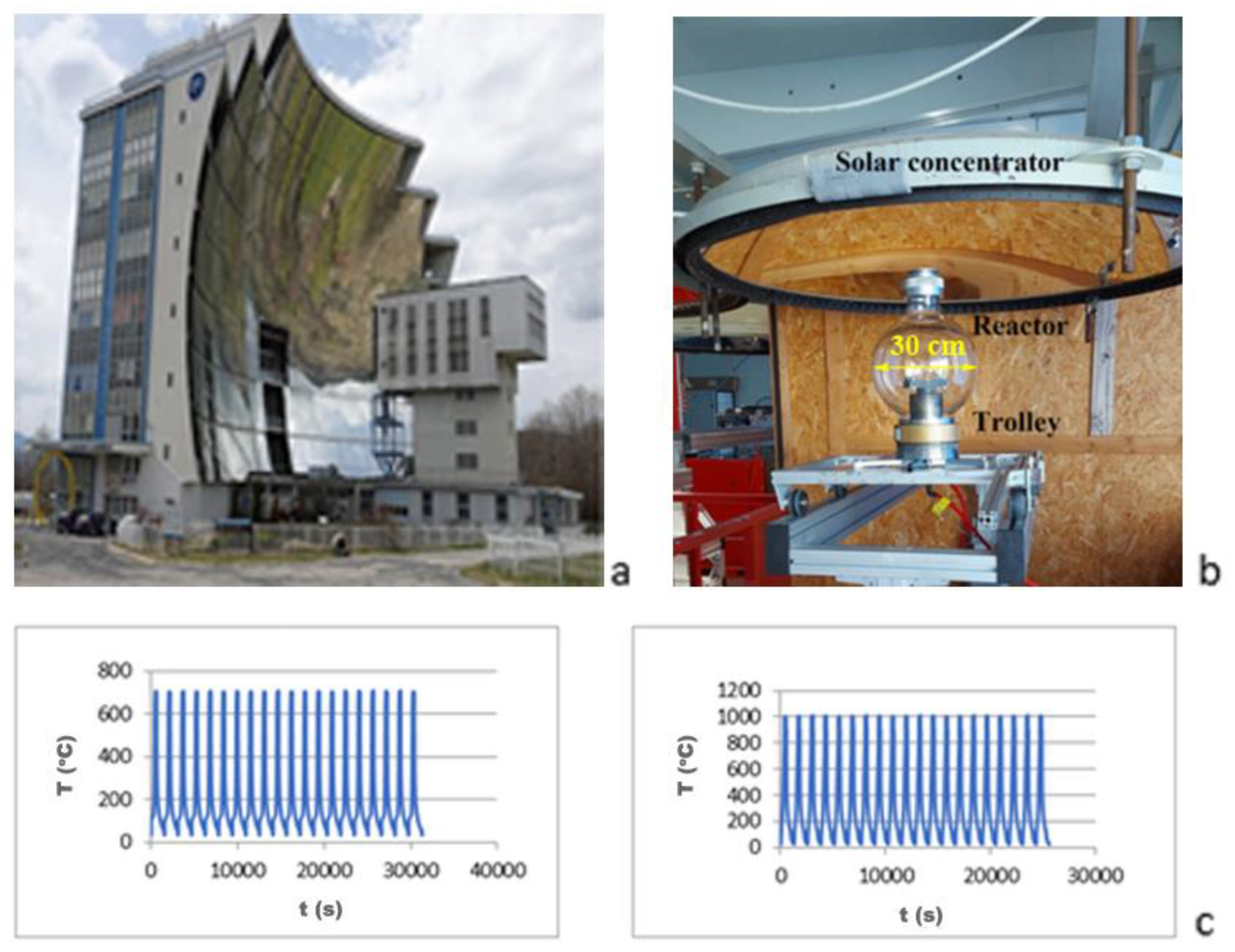
2. Experimental Materials and Methods

The Inconel 718 alloy sample subjected to the thermal test exhibits mackled polyhedral grains and precipitates along the grain boundaries. Its microstructure is shown in Figure 1, and the chemical composition was analyzed using SEM-EDS area scanning and is presented in Table 1.
For testing in the solar furnace, parallelepiped-shaped samples with a square base and a height orientated in the deformation direction were used (l = 7 mm, H = 10 mm). The tests were conducted at the PROcesses, Materials, and Solar Energy laboratory with funding from the project Specific Programme ‘Capacities’—Study of Variation of the Mechanical Properties of Superalloys Inconel 718 and Rene 41 under Thermal Shock (TERMOINCORENE). The testing was performed in the temperature range of 400–1000 °C through thermal shocks lasting 30 s. The experimental device is shown in Figure 2. A type K thermocouple was used to measure temperatures up to 1300 °C. For data acquisition, the Data Logger Model GL220 (Dataq Instruments Inc., Akron, OH, USA) was used—a portable, multifunctional device designed for data acquisition and recording in various industrial and research applications. It features 10 analog input channels, capable of measuring temperatures, voltages, and other electrical signals. The GL220 has a sampling rate of up to 10 ms, 2 GB of internal memory, and supports SD cards for extended storage. It is equipped with a color LCD screen, a USB interface, and PC connectivity for real-time monitoring and analysis. This makes it ideal for industrial applications, research, and environmental testing. The measurements were conducted in June, a period of maximum solar flux. During testing, three instances of solar flux fluctuations were observed, but these were eliminated from the analysis.
Microhardness measurements were carried out using Falcon’s 500 Series equipment (Falcon Corporation, Tokyo, Japan) for Micro Vickers, Vickers, and Micro Brinell tests. The hardness measurements were conducted along the height of the samples, after appropriate surface preparation, from the surface opposite to the shock towards the shock application surface. The procedure was carried out in accordance with ISO 6507-1/2023 [61]. The applied load was 500 gf, and the force application time was 12–13 s.
The microscopic analysis of the samples, etched with Adler reagent, was performed using an Olympus optical microscope (Olympus Corporation, Tokyo, Japan). For morphological characterization and elemental chemical analysis, a HITACHI SU5000 electron microscope (Hitachi High-Tech Group, Tokyo, Japan) was used.
The X-ray diffraction (XRD) patterns of the analyzed samples were acquired using a Rigaku Ultima IV diffractometer (Rigaku Corporation, Tokyo, Japan), operating in Bragg–Brentano geometry with CuKα radiation and a D/teX Ultra 1D detector equipped with a graphite monochromator. Data collection was performed over an angular range of 2θ = [20°–100°], with a step size of 0.05° and a scanning speed of 1.5°/min. Qualitative phase identification was carried out using the Rigaku PDXL version 2.0 by Rigaku Corporation (Tokyo, Japan) in conjunction with the ICDD PDF-5+ 2024 database.

3. Experimental Results and Discussion

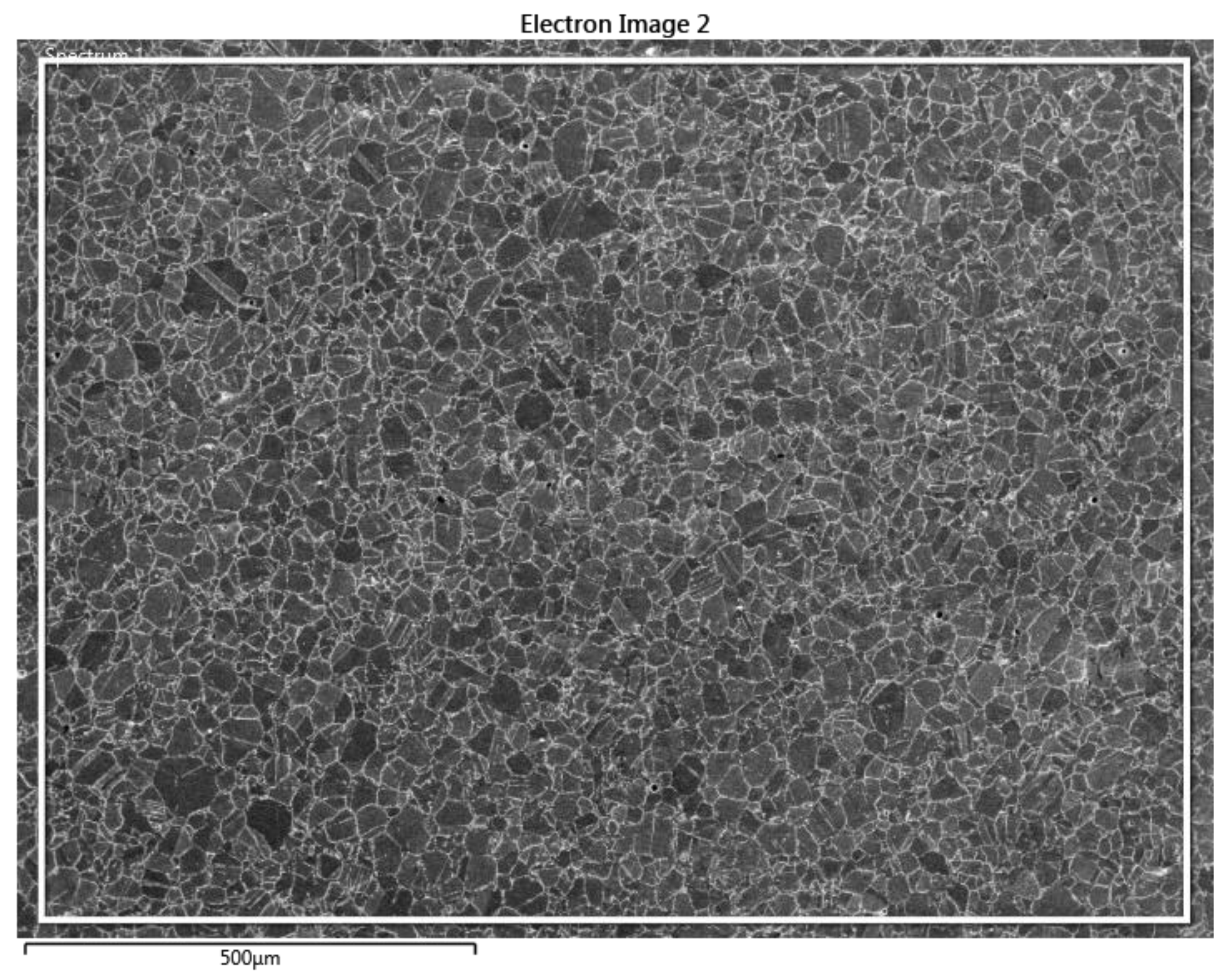
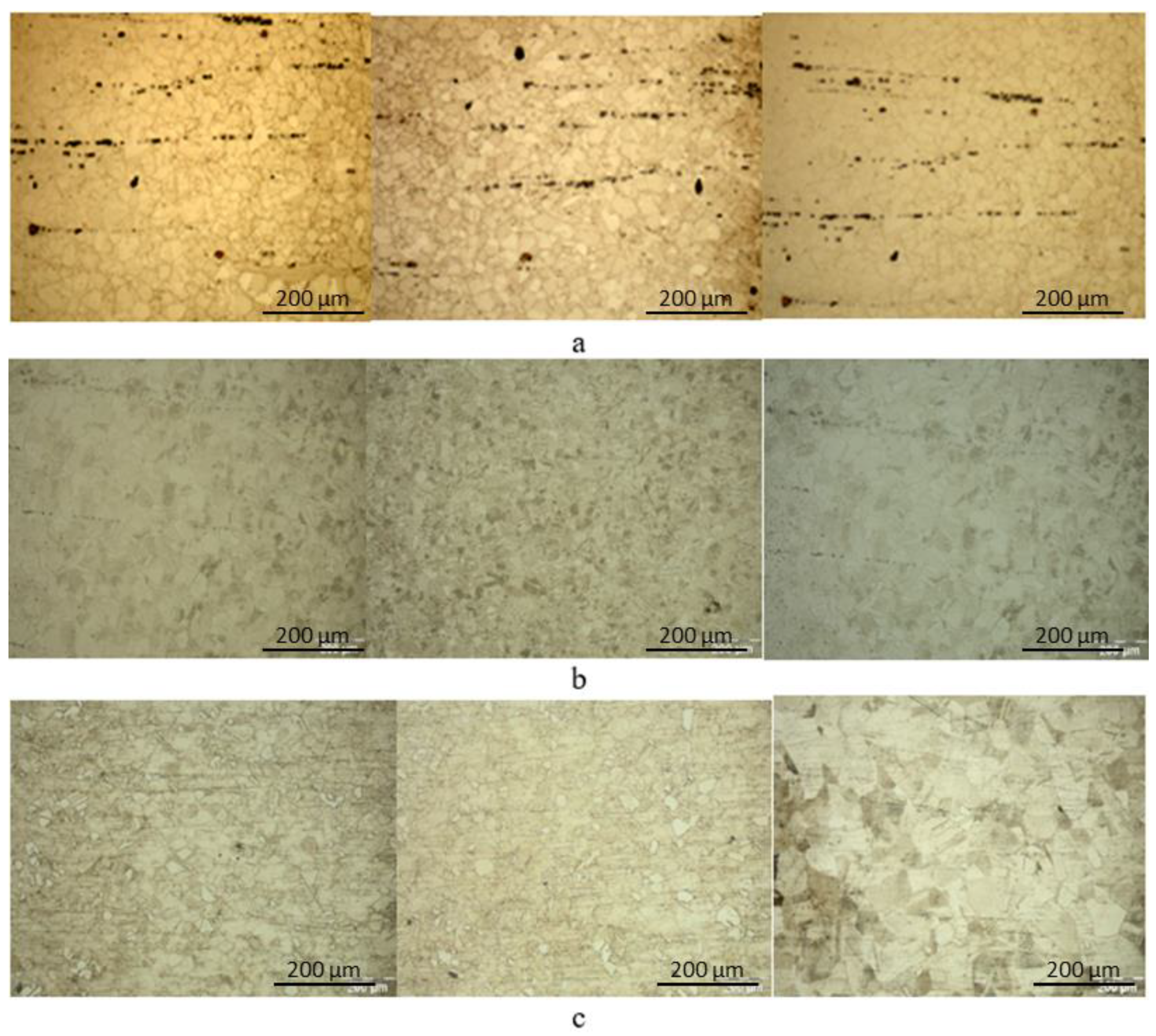
3.1. The Microstructural Analysis

The evolution of the alloy microstructure along the height of the sample by applying thermal shocks according to the temperature of the shocks is presented in Figure 3.
Increasing the heat shock temperature shows an increase in grains with temperature, with a more obvious increase near the thermal shock surface for a temperature of 1000 °C (Figure 3).
SEM analysis highlighted the morphology and the distribution of the secondary phases (Figure 4 and Figure 5). The large Ni3Nb intragranular precipitates are arranged in parallel string-like formations orientated perpendicular to the surface where the thermal shocks were applied. The Ni3Nb, γ″ phases within the grain boundaries have an acicular structure (Figure 5a), and in some areas, they even have spatial developments (Figure 5b).
The evolution with the temperature of the thermal shock of the thickness of the oxide layers formed is presented in Figure 6.
The cross-sectional SEM analysis in Figure 6 highlights the increase in the thickness of the layers with the shock temperature, with the oxide–metal interface marked. The elemental chemical composition maps obtained through SEM-EDS reveal the distribution of alloying elements in the oxide layers (Figure 7, Figure 8, Figure 9 and Figure 10), emphasizing the protective role of chromium.
At 700 °C, the oxide layer formed is uniform (Figure 7). Except for chromium, whose concentration is higher at the metal–oxide interface; the other elements show a distribution similar to that of the alloy.
At 800 °C, the oxide layer formed is continuous and compact. From a chemical composition perspective, it exhibits a stratified structure (Figure 8). The chromium oxide layer located at the metal–oxide interface is uniform and dense.
The increase in temperature, along with the growth in oxide layer thickness, leads to a spatial distribution of chromium within the layer and the formation of a less chromium-rich layer at the metal–oxide interface.
At 900 °C, the growth of the oxide layer is associated with the occurrence of degradation processes (Figure 9). The chromium layer at the metal–oxide interface is dense but thinner.
At 1000 °C, the layer begins to show signs of degradation. The chromium oxide layer at the metal–oxide interface becomes thinner, and Cr oxide is dispersed toward the upper regions (Figure 8).
In the literature, reference is made to the essential role of Cr and Al in corrosion resistance [2]. The characterization of oxide layers has highlighted the role of chromium at the metal–oxide interface. The aluminum present in the alloy is distributed in precipitates that enhance hardness and stability at high temperatures. No significant presence was observed at the interface region or in the surface layer.
The Inconel 718 alloy is widely utilized in aerospace and energy applications due to its exceptional high-temperature strength, corrosion resistance, and overall mechanical performance. The behavior of these alloys is critically influenced by the diffusion of alloying elements, which governs the formation, growth, and stability of strengthening precipitates, as well as other microstructural features.
Chromium is essential in corrosion resistance, as it forms a protective Cr2O3 layer on the alloy’s surface, enhancing its durability in high-temperature environments. It also plays a role in the stabilization and dissolution of carbides. Chromium diffusion is relatively slow compared to other elements. For Inconel 718, the chromium-rich layer is ensured by the alloy’s high chromium concentration. The thickness of the chromium-rich layer increases with rising temperature, but the structure degrades.
At 700–800 °C, the layer remains compact, perfectly covering the metal–oxide interface. However, starting at 900 °C, degradation processes appear in the upper region (Figure 9 and Figure 10), although a compact layer remains near the interface, becoming increasingly thinner. The concentration of other elements in the surface layer increases with rising temperature. Their presence in the surface layer must be discussed in relation to their role in the alloy. Niobium is a principal strengthening element in Inconel 718. The γ″ (Ni3Nb) phase significantly enhances tensile strength and creep resistance. The diffusion behavior of niobium is key in controlling the size, distribution, and stability of these precipitates. At lower temperatures, limited diffusion ensures a fine dispersion of the γ″ phase. Higher temperatures accelerate coarsening and phase instability, leading to a decline in mechanical properties. As the temperature increases, the chromium-rich layer becomes enriched in niobium, forming a niobium-rich layer on top of the chromium-containing layer (Figure 8). This results in the depletion of niobium in the alloy near the surface. In the oxide layer, niobium tends to accumulate in degraded regions of the chromium-rich layer (Figure 9 and Figure 10). Its role in maintaining alloy stability at 900–1000 °C is less significant than that of titanium. Titanium contributes to alloy strengthening through the formation of the γ′ (Ni3(Al,Ti)) phase. Although the proportion of the γ′ phase in Inconel 718 is much lower than that of the γ″ phase, it ensures stability at temperatures above 700 °C. Overheating, through the diffusion of titanium from the alloy into the oxide layer, influences the balance between the γ′ and γ″ phases. The increased diffusion of titanium at high temperatures may lead to phase transformations that compromise the alloy’s strength and creep resistance. At 800 °C, titanium is present in the surface layer, with a preference for distribution in the chromium-rich layer at the oxide–metal interface (Figure 8). At 900 °C, the titanium content in the layer increases and is distributed relatively uniformly, similar to that in the bulk alloy (Figure 9). Carbon, although present in low concentrations, plays an important role in creep resistance and grain boundary stability through the formation of carbides. Carbon diffusion is much faster than that of metallic alloying elements and forms a carbon-rich zone at the surface of the oxide layer, which increases with temperature (Figure 7, Figure 8 and Figure 9). The decarburization process near the surface has a negative effect on the alloy’s properties by reducing the percentage of hard phases at the grain boundary, as well as the stability of the grain boundary and creep resistance.
Molybdenum is an important alloying element in Inconel 718, significantly contributing to the alloy’s overall performance, particularly at high temperatures. Mo improves the alloy’s strength by dissolving into the nickel matrix and plays a crucial role in maintaining stability and mechanical properties under high-temperature conditions. It also contributes to strengthening through the formation of carbides, which, when present at grain boundaries, enhance the alloy’s stability. Additionally, Mo influences the precipitation kinetics of the γ″ (Ni3Nb) phase, promoting the growth of precipitates.
By controlling diffusion under high-temperature conditions, molybdenum plays a pivotal role in maintaining the alloy’s mechanical integrity and corrosion resistance. Structurally, starting at 800 °C, the molybdenum-rich diffusion layer, similar to niobium, flanks the chromium-rich layer (Figure 8 and Figure 9). The increasing thickness of the molybdenum layer indicates the surface depletion of the alloy, leading to a decline in its properties.
Copper diffusion in the surface layer is comparable to that of niobium and titanium. At 900 °C, it is uniformly distributed in the corrosion layer, with a concentration much higher than in the metallic mass (Figure 9). Although present in low concentrations, copper influences corrosion resistance, microstructural stability, and grain boundary integrity through small precipitates. Overheating at high temperatures, through the diffusion of elements, affects the alloy’s microstructure and properties. The diffusion processes occurring during overheating lead to a reduction in mechanical properties and a decrease in the alloy’s lifespan. The increase in temperature leads to the intensification of the degradation processes of the protective chromium oxide (Cr2O3) layer. These processes are caused by thermal cycling and the diffusion of alloying elements into the layer. Repeated heating and cooling cycles induce differential thermal expansion between the substrate and the oxide layer. This results in the development of microcracks and spallation of the Cr2O3 layer, which reduces its protective function. The phenomenon is clearly visible at 900 °C and 1000 °C (Figure 9 and Figure 10). The diffusion of alloying elements from the substrate into the oxide layer can alter its composition and structure, potentially forming complex oxides with inferior protective properties compared to pure Cr2O3 (Figure 11, Table 2).

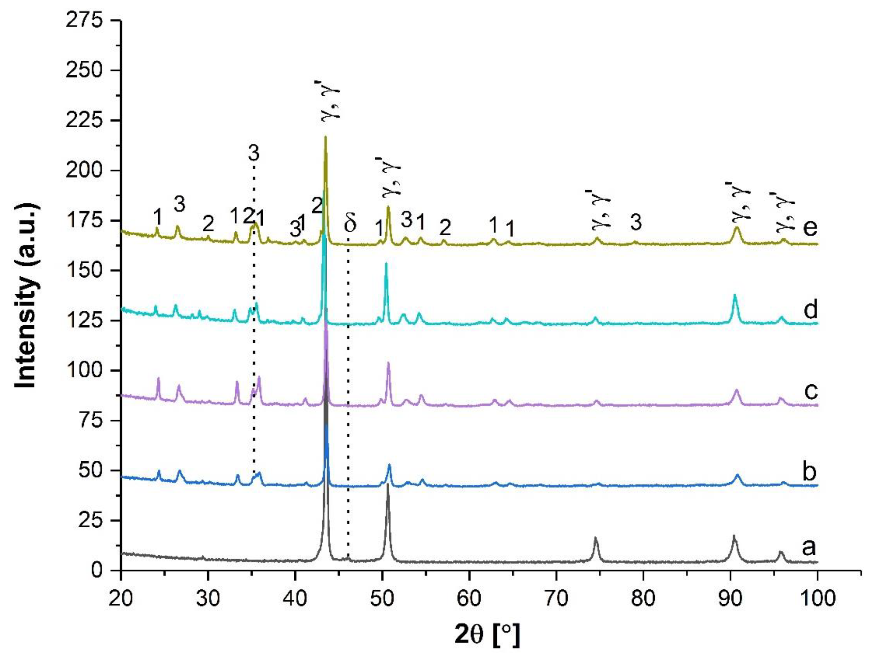
3.2. Qualitative Phase Analysis by X-Ray Diffraction

The X-ray diffraction (Figure 11) indicated, for all analyzed samples, the presence of diffraction lines associated with the matrix γ of the alloy with a structure from the space group 225:Fm-3m and the phase γ′ belonging to the space group 221:Pm-3m [35]. For the non-cycled alloy sample and the Inconel 800 °C—9c sample, the presence of the phase δ specific to this alloy is also observed [35].
The crystalline phases corresponding to the substrate, as well as those formed at the surface by thermal cycling, are shown in the following table.
According to the literature data, a high degree of alloying determines the transformation of M23C6 carbide into M6C carbide. Through the qualitative analysis of the phase with X-ray diffraction, no carbides were identified, but the presence of the δ, Ni3Nb phase was identified [28,29].

3.3. The Influence of Thermal Shocks on the Microhardness

Since treatment at low temperatures (400–600 °C) did not produce significant thermally influenced areas in relation to the thermal shock surface, the microhardness evolution was characterized by measurements on the shock surface (Figure 12). The surface microhardness measured at 400 °C and 500 °C was lower than that of the unshocked reference sample. Due to the precipitation processes occurring, the hardness increased with the shock application temperature. At 600 °C, which is at the lower limit of the aging treatment, the microhardness values oscillated around the reference microhardness curve.
To evaluate the influence of overheating at temperatures higher than the recommended limit for Inconel 718, the variation in microhardness was measured along the height of the sample, from the surface opposite to the one exposed to thermal shock (Figure 13).
The surface microhardness at the point of application of the 20 thermal shocks remains nearly identical across all shock temperatures.
In the Heat-Affected Zone (HAZ) at 700 °C, the microhardness increases rapidly, reaching a maximum at approximately 4 cm from the shock-exposed surface, corresponding to the region of maximum precipitation. For samples treated at 800 °C and 900 °C, microhardness increases more gradually, indicating a more extended thermally affected zone. At 1000 °C, the thermal influence extends along the entire length (height) of the sample, affecting the material uniformly. The decrease in hardness near the shock application surface is explained by the diffusion and dissolution processes of the hard phases. The decrease in hardness at high temperatures is consistent with the research conducted by Schvart, which examined the degradation of die quality in copper alloys under deformation [10], and by Ghiban et al., who investigated the hot-working behavior of the Inconel 718 superalloy [48].

4. Conclusions

The evolution of the Inconel 718 superalloy under overheating conditions was investigated within the temperature range of 400–1000 °C over 20 overheating cycles.
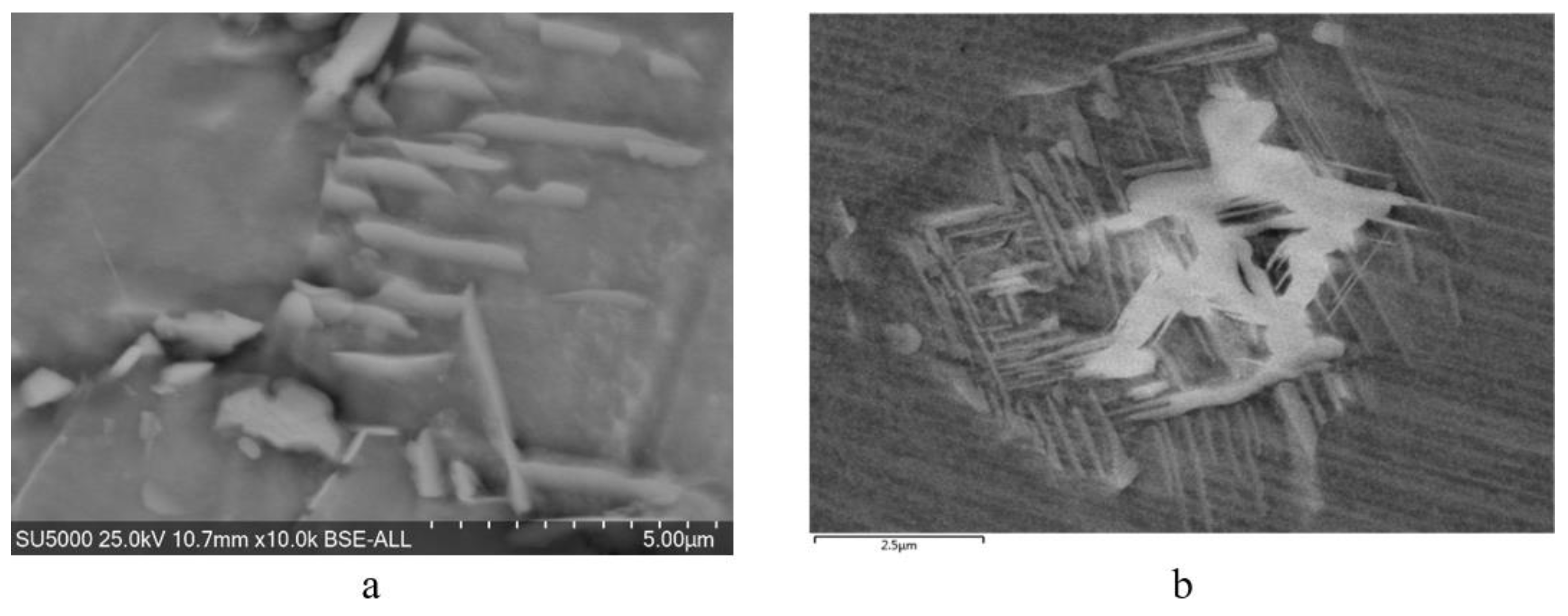
  • Structural Stability: At temperatures below 700 °C, the alloy retains its forged structure, characterized by twinned polyhedral grains and rows of hard phases aligned with the deformation direction (Figure 3a).
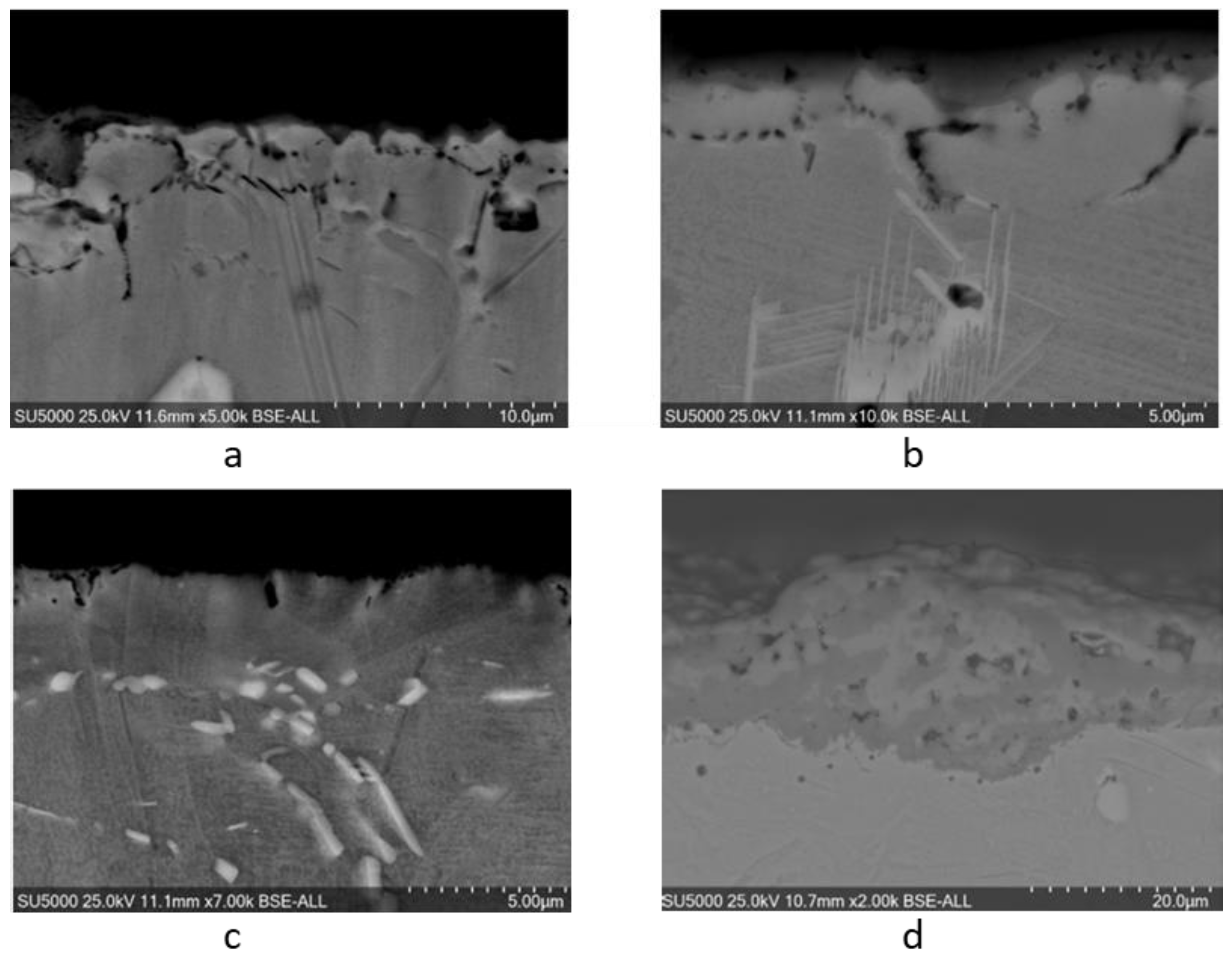
  • Microstructural Changes at Higher Temperatures: In the 700–1000 °C range, the alignment of hard phases becomes less distinct, while twinned polyhedral grains persist but with increased grain size (Figure 3b,c). Additionally, secondary-phase precipitates decrease in number and grow in size due to dissolution and coalescence phenomena.
  • Delta-Phase Formation: At 800 °C, after 20 overheating cycles, delta-phase precipitates were identified.
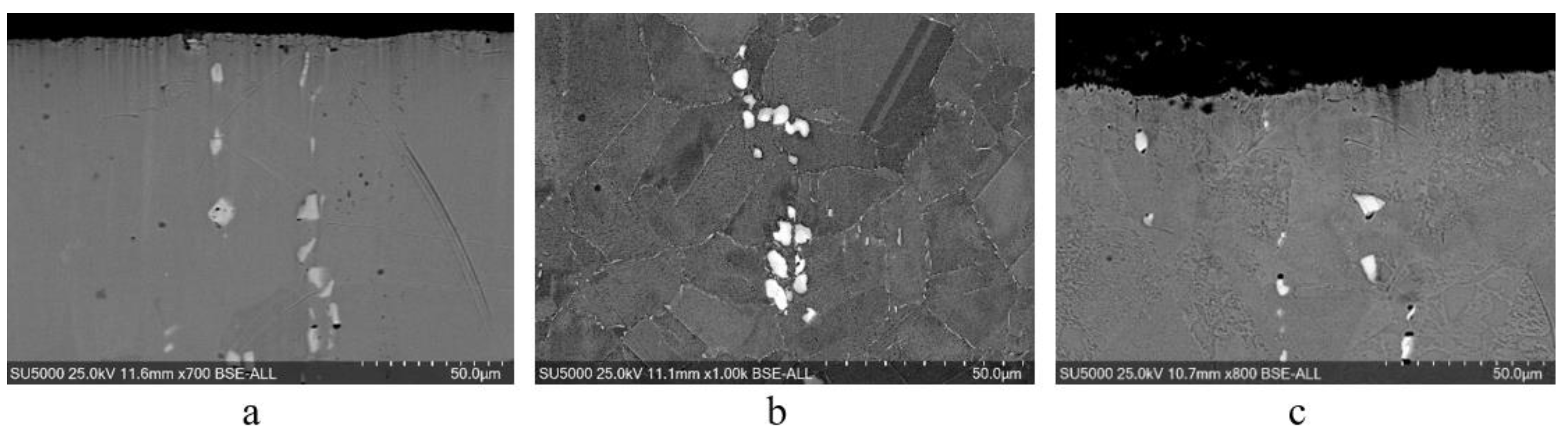
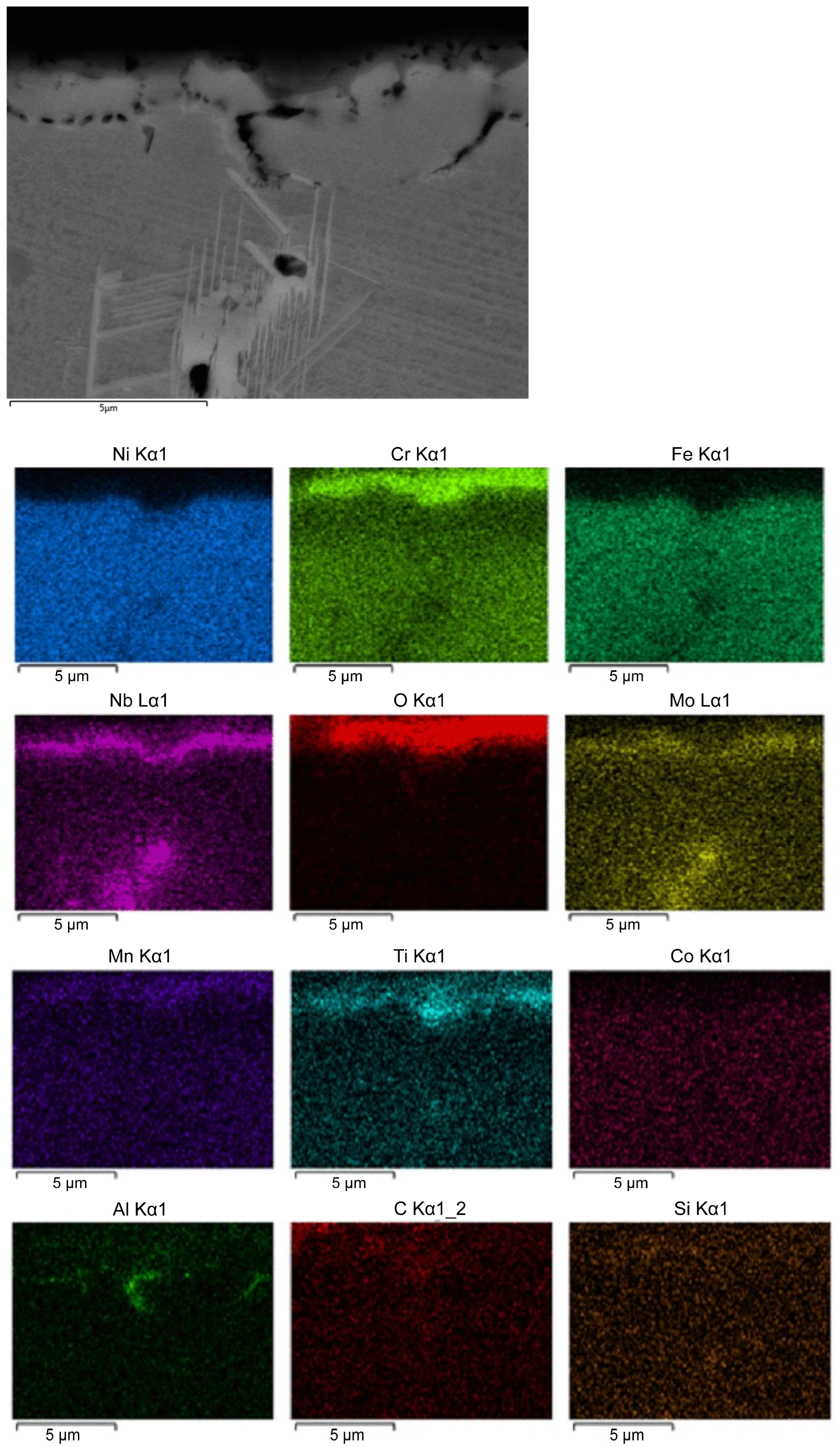
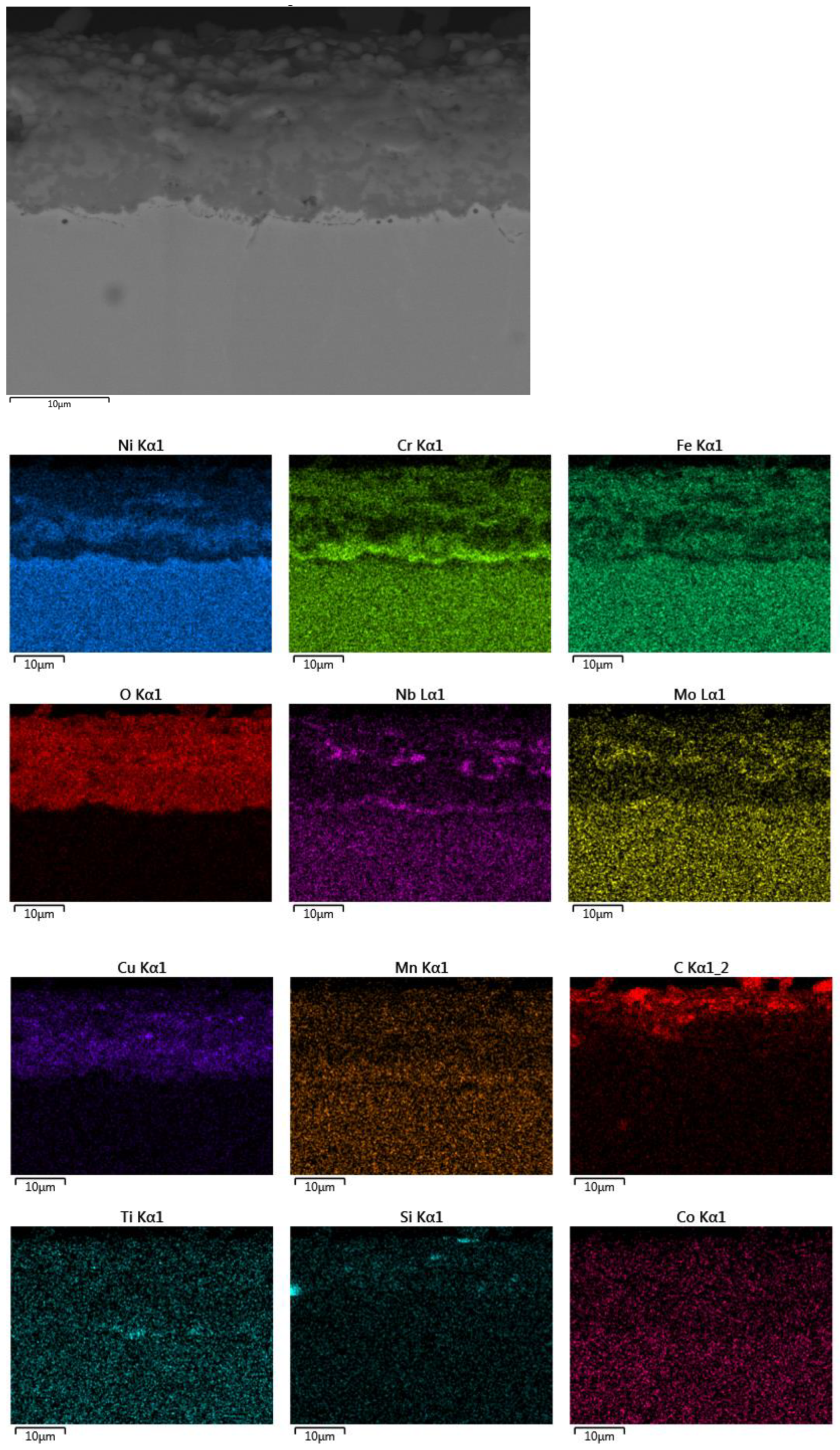
  • Surface Layer Integrity and Corrosion Resistance: The protective surface layers formed on the alloy remain compact and continuous at lower temperatures, particularly the chromium-rich layer, which mirrors the underlying metallic surface and enhances corrosion resistance. The diffusion and positioning of alloying elements in the oxide layers have been highlighted. However, increasing the temperature initiates degradation processes in these layers, reducing their compactness and continuity, which subsequently lowers corrosion resistance.
  • The experimental data show the diffusion of carbon into the oxide layer, which, according to the research conducted by Li Yanlei and others [62], can diffuse from the bulk metal towards the surface layer, contributing to the formation of compounds that affect the corrosion behavior of the alloy.
  • Hardness Evolution: In the 400–600 °C range, surface hardness values are generally lower than those of the reference sample, except at 600 °C, where aging and secondary-phase precipitation begin, yielding hardness values close to the reference. In the 800–1000 °C range, significant hardness reductions occur near the surface subjected to thermal shock. At 1000 °C, this decrease extends almost through the entire sample thickness, from the exposed surface to the base.
  • Operational Limitations: The severe hardness reduction at high temperatures suggests that even short-term overheating can significantly impair the mechanical performance of Inconel 718. Therefore, its use in high-stress applications at elevated temperatures is not recommended.
  • For applications in the energy, aerospace, and other highly demanding fields, managing phase equilibrium and structural transformations can prevent processes that lead to the loss of mechanical strength and increased brittleness.
  • Continuing research with longer holding times at high temperatures could provide essential data for developing effective thermal regulation strategies, thereby improving the durability and reliability of materials used in extreme conditions.

Author Contributions

Conceptualization, M.A., E.R.A.U., A.-D.R. and D.A.N.; methodology, E.R.A.U., D.-C.A., D.A.N., A.H. and M.A.; software, D.A.N. and E.R.A.U.; validation, E.R.A.U., D.A.N. and M.A.; formal analysis, D.A.N.; investigation, E.R.A.U., S.G.M., D.A.N., D.-C.A., A.-D.R., A.H. and L.M.C.; resources, E.R.A.U.; data curation, M.I.P. and R.S.; writing—original draft preparation, E.R.A.U. and M.A.; writing—review and editing and visualization, D.A.N. and M.I.P.; supervision, M.A. and D.-C.A.; project administration, M.A. All authors have read and agreed to the published version of the manuscript.

Funding

This project has received funding from the European Union’s Horizon 2020 research and innovation program under grant agreement No 823802. We thank the CNRS-PROMES laboratory, UPR 8521, belonging to the French National Centre for Scientific Research (CNRS), for access to its installations and the support of scientific and technical staff, within this grant agreement (No 823802) (SFERA-III).

Institutional Review Board Statement

Not applicable.

Informed Consent Statement

Not applicable.

Data Availability Statement

The original contributions presented in the study are included in the article, further inquiries can be directed to the corresponding author.

Acknowledgments

We thank the team of the PROMES Laboratory, Font Romeu-Odeillo, especially our colleague Emmanuel Guillot, for their support in conducting thermal shock testing using solar energy as part of the research carried out for the project “Study of the variation of the mechanical properties of the superalloys Inconel 718 and Rene 41 under thermal shock—TERMOINCORENE”.

Conflicts of Interest

The authors declare no conflicts of interest.

Abbreviations

SEM, scanning electron microscopy; EDS, energy-dispersive spectroscopy; XRD, X-ray diffraction; HV, Vickers hardness; cps, counts per second; γ′ (Ni3(Al,Ti), intermetallic compound; γ″ Ni3Nb, intermetallic compound; Cr2O3, Cr oxide; Ti0.95 Nb0.9 5O4, titanium compound.

References

  1. Gradtl, P.; Tikner, D.; Williams, B.; Smith, T.; Kantsos, C. Extreme Temperature Additively Manufactured GRX-810 Alloy Development and Hot-fire Testing for Liquid Rocket Engines. In Proceedings of the AIAA SciTech Forum and Exposition, Orlando, FL, USA, 8–12 January 2024; Available online: https://ntrs.nasa.gov/citations/20240000067 (accessed on 12 September 2024).
  2. Bhadeshia. Available online: http://www.phase-trans.msm.cam.ac.uk/2003/Superalloys/superalloys.html (accessed on 10 October 2024).
  3. Available online: https://www.sciencedirect.com/topics/materials-science/nickel-based-superalloys (accessed on 10 October 2020).
  4. Pollock, T.M.; Tin, S. Nickel-Based Superalloys for Advanced Turbine Engines: Chemistry, Microstructure and Properties. J. Propuls. Power 2006, 22, 361–374. [Google Scholar] [CrossRef]
  5. Bujoreanu, L. Superalloys-Lecture Notes; UTGA: Iasi, Romania, 2017. [Google Scholar]
  6. Marsh, C. The Mechanical Properties and Deformation Behavior of Heat Treated Versus As-Received Inconel X ed Inconel X-750. Ph.D. Thesis, University of South Carolina, Columbia, SC, USA, 2018. [Google Scholar]
  7. Maj, P.; Adamczyk-Cieslak, B.; Slesik, M.; Mizera, J. The Precipitation Processes and Mechanical Properties of Aged Inconel 718 Alloy After Annealing. Arch. Metall. Mater. 2017, 62, 1695–1702. [Google Scholar] [CrossRef]
  8. Vincent, R. Precipitation around and welds in the nickel-base superalloy Inconel 718. Acta Metall. 1985, 33, 1205–1216. [Google Scholar] [CrossRef]
  9. Feng, Q.; Wu, Y.; Li, J.; Cai, Y.; Zhang, Y.; Liu, J.; Liu, T. Effects of intermediate temperature on the grain boundary and γ’ precipitates of nickel-based powder superalloy under interrupted cooling. J. Alloys Compd. 2022, 922, 166310. [Google Scholar] [CrossRef]
  10. Schwartz, M.; Ciucă, I. Research on Structural Changes of the Materials Used for Manufacturing Extrusion Tools. Ph.D. Thesis, Politehnica University of Bucharest, Bucharest, Romania, 2016. [Google Scholar]
  11. Huang, H.; Liu, G.; Wang, H.; Wang, Z.; Zhang, H.; Shao, Y. Effect of cooling rate and resulting microstructure on tensile properties and deformation mechanisms of an advanced PM nickel-based superalloy. J. Alloys Compd. 2019, 805, 1254–1259. [Google Scholar] [CrossRef]
  12. Babu, S.; Miller, M.K.; Vitek, J.M.; David, S.A. Characterization of the microstructure evolution in a nickel base superalloy during continuous cooling conditions. Acta Mater. 2001, 49, 4149–4160. [Google Scholar] [CrossRef]
  13. Wu, H.; Li, J.; Liu, F.; Huang, L.; Zeng, X.; Fang, Q.; Huang, Z.; Jiang, L. A high-throughput methodology search for the optimum cooling rate in an advanced polycrystalline nickel base superalloy. Mater. Des. 2017, 128, 176–181. [Google Scholar] [CrossRef]
  14. Singh, A.R.P.; Nag, R.J.; Hwang, J.Y.; Viswanathan, G.B.; Tiley, J.; Srinivasan, R.; Fraser, H.L.; Banerjee, R. Influence of cooling rate on the development of multiple generations of γ’ precipitates in a commercial nickel base superalloy. Mater. Charact. 2011, 62, 878–886. [Google Scholar] [CrossRef]
  15. Sarosi, P.; Wang, B.; Simmons, J.; Wang, Y.; Mills, M. Formation and multimodal distributions of γ′ in a nickel-base superalloy during interrupted continuous cooling. Scr. Mater. 2007, 57, 767–770. [Google Scholar] [CrossRef]
  16. Liao, Y.S.; Shiue, R.H. Carbide tool wear mechanism in turning of Inconel 718 superalloy. Wear 1996, 193, 16–24. [Google Scholar] [CrossRef]
  17. Basak, A.; Das, S. Carbide Formation in Nickel-Base Superalloy MAR-M247 Processed Through Scanning Laser Epitaxy (SLE). In Proceedings of the 27th Annual International Solid Freeform Fabrication Symposium—An Additive Manufacturing Conference, Austin, TX, USA, 8–10 August 2016. [Google Scholar]
  18. Ranganath, S.; Guo, C.; Holt, S. Experimental Investigations into the Carbide Cracking Phenomenon on Inconel 718 Superalloy Material. In Proceedings of the ASME 2009 International Manufacturing Science and Engineering Conference, West Lafayette, IN, USA, 4–7 October 2010; pp. 33–39. [Google Scholar] [CrossRef]
  19. Tang, Y.T.; Wilkinson, A.J.; Reed, R.C. Grain Boundary Serration in Nickel-Based Superalloy Inconel 600: Generation and Effects on Mechanical Behavior, Topical Collection: Superalloys and Their Applications. Metall. Mater. Trans. 2018, 49, 4324–4342. [Google Scholar] [CrossRef]
  20. Mitchell, R.J.; Preuss, M.; Tin, S.; Hardy, M.C. The influence of cooling rate from temperatures above the γ′ solvus on morphology, mismatch and hardness in advanced polycrystalline nickel-base superalloys. Mater. Sci. Eng. 2008, 473, 158–165. [Google Scholar] [CrossRef]
  21. Osada, T.; Gu, Y.; Nagashima, N.; Yuan, Y.; Yokokawa, T.; Harada, H. Optimum microstructure combination for maximizing tensile strength in a polycrystalline superalloy with a two-phase structure. Acta Mater. 2013, 61, 1820–1829. [Google Scholar] [CrossRef]
  22. Hong, H.U.; Kim, I.S.; Choi, B.G.; Kim, M.Y.; Jo, C.Y. The effect of grain boundary serration on creep resistance in a wrought nickel-based superalloy. Mater. Sci. Eng. 2009, 517, 125–131. [Google Scholar] [CrossRef]
  23. Chen, Y.; Yu, H.; Chen, Y.; Di, H.; Xu, W. The strengthening effects and mechanisms of alloying elements on interfaces for multiphase Ni-based superalloys: A first-principles study. J. Mater. Res. Technol. 2023, 23, 4802–4848. [Google Scholar] [CrossRef]
  24. Lee, H.; Lee, S. The morphology and formation of gamma prime in nickel-base superalloy. J. Mater. Sci. Lett. 1990, 9, 516–517. [Google Scholar] [CrossRef]
  25. Jia, L.; Cui, H.; Yang, S.; Lv, S.; Xie, X.; Qu, J. As-cast microstructure and homogenization kinetics of a typical hard-to-deform Ni-base superalloy. J. Mater. Res. Technol. 2023, 23, 5368–5381. [Google Scholar] [CrossRef]
  26. Jovanović, M.; Tadić, S. Influence of high-temperature exposure on the microstructure and creep resistance of IN-100 superalloy. J. Mater. Sci. Lett. 1993, 30, 3–12. [Google Scholar] [CrossRef]
  27. Grosdidier, T.; Hazotte, A.; Simon, A. Precipitation and dissolution processes in γ/γ′ single crystal nickel-based superalloys. Mater. Sci. Eng. A-Struct. Mater. Prop. Microstruct. Process. 1998, 256, 183–196. [Google Scholar] [CrossRef]
  28. Nunes, R.M.; Pereira, D.; Clarke, T.; Hirsch, T.K. Delta Phase Characterization in Inconel 718 Alloys Through X-ray Diffraction. ISIJ Int. 2015, 55, 2450–2454. [Google Scholar] [CrossRef]
  29. Guan, H.; Jiang, W.; Lu, J.; Zhang, Y.; Zhang, Z. Precipitation of δ phase in Inconel 718 superalloy: The role of grain boundary and plastic deformation. Mater. Today Commun. 2023, 36, 106582. [Google Scholar] [CrossRef]
  30. Xu, L.; Chai, Z.; Peng, B.; Zhou, W.; Chen, X. Effect of heat treatment on microstructures and mechanical properties of Inconel 718 additively manufactured using gradient laser power. Mater. Sci. Eng. A 2023, 868, 144754. [Google Scholar] [CrossRef]
  31. Deng, D.; Moverare, J.; Peng, R.L.; Söderberg, H. Microstructure and anisotropic mechanical properties of EBM manufactured Inconel 718 and effects of post heat treatments. Mater. Sci. Eng. A 2017, 693, 151–163. [Google Scholar] [CrossRef]
  32. Bansal, A.; Zafar, S.; Sharma, A.K. Influence of heat treatment on microstructure of Inconel 718 microwave clads. Surf. Eng. 2017, 33, 167–174. [Google Scholar] [CrossRef]
  33. Li, P.; Zhou, J.; Gong, Y.; Meng, X.; Lu, J. Effect of post-heat treatment on the microstructure and mechanical properties of laser metal deposition Inconel 718. J. Mech. Sci. Technol. 2021, 35, 2871–2878. [Google Scholar] [CrossRef]
  34. Anbarasan, N.; Gupta, B.K.; Prakash, S.; Muthukumar, P.; Oyyaravelu, R.; Kumar, R.J.F.; Jerome, S. Effect of heat treatment on the microstructure and mechanical properties of Inconel 718. Mater. Today Proc. 2018, 5, 7716–7724. [Google Scholar] [CrossRef]
  35. Yadav, P.C.; Sahu, S.; Subramaniam, A.; Shekhar, S. Effect of heat-treatment on microstructural evolution and mechanical behaviour of severely deformed Inconel 718. Mater. Sci. Eng. A 2018, 715, 295–306. [Google Scholar] [CrossRef]
  36. Fan, Q.; Li, J.; Zheng, L.; Hao, C.; Zhang, Q.; Wang, Y. Effect of heat treatment on microstructure and mechanical properties of selective laser melted Inconel 718 alloy. PLoS ONE 2024, 19, e0309156. [Google Scholar] [CrossRef]
  37. Chang, L.; Sun, W.; Cui, Y.; Zhang, F.; Yang, R. Effect of heat treatment on microstructure and mechanical properties of the hot-isostatic-pressed Inconel 718 powder compact. J. Alloys Compd. 2014, 590, 227–232. [Google Scholar] [CrossRef]
  38. Raghavan, S.; Zhang, B.; Wang, P.; Sun, C.N.; Nai, M.L.S.; Li, T.; Wei, J. Effect of different heat treatments on the microstructure and mechanical properties in selective laser melted INCONEL 718 alloy. Mater. Manuf. Process. 2017, 32, 1588–1595. [Google Scholar] [CrossRef]
  39. Popovich, A.A.; Sufiiarov, V.S.; Polozov, I.A.; Borisov, E.V. Microstructure and mechanical properties of Inconel 718 produced by SLM and subsequent heat treatment. Key Eng. Mater. 2015, 651, 665–670. [Google Scholar] [CrossRef]
  40. Popovich, V.A.; Borisov, E.V.; Popovich, A.A.; Sufiiarov, V.S.; Masaylo, D.V.; Alzina, L. Impact of heat treatment on mechanical behaviour of Inconel 718 processed with tailored microstructure by selective laser melting. Mater. Des. 2017, 131, 12–22. [Google Scholar] [CrossRef]
  41. Huang, W.; Yang, J.; Yang, H.; Jing, G.; Wang, Z.; Zeng, X. Heat treatment of Inconel 718 produced by selective laser melting: Microstructure and mechanical properties. Mater. Sci. Eng. A 2019, 750, 98–107. [Google Scholar] [CrossRef]
  42. Tajyar, A.; Brooks, N.; Holtham, N.; Rowe, R.; Newell, D.J.; Palazotto, A.N.; Davami, K. Effects of a modified heat-treatment on microstructure and mechanical properties of additively manufactured Inconel 718. Mater. Sci. Eng. A 2022, 838, 142770. [Google Scholar] [CrossRef]
  43. Schneider, J.; Lund, B.; Fullen, M. Effect of heat treatment variations on the mechanical properties of Inconel 718 selective laser melted specimens. Addit. Manuf. 2018, 21, 248–254. [Google Scholar] [CrossRef]
  44. Qi, H.; Azer, M.; Ritter, A. Studies of standard heat treatment effects on microstructure and mechanical properties of laser net shape manufactured Inconel 718. Metall. Mater. Trans. A 2009, 40, 2410–2422. Available online: https://experts.illinois.edu/en/publications/studies-of-standard-heat-treatment-effects-on-microstructure-and- (accessed on 21 October 2024). [CrossRef]
  45. Li, X.; Shi, J.; Wang, C.; Cao, G.; Russell, A.; Zhou, Z.; Li, C.; Chen, G. Effect of heat treatment on microstructure evolution of Inconel 718 alloy fabricated by selective laser melting. J. Alloys Compd. 2018, 764, 639–649. [Google Scholar] [CrossRef]
  46. Deng, D.; Peng, R.L.; Brodin, H.; Moverare, J. Microstructure and mechanical properties of Inconel 718 produced by selective laser melting: Sample orientation dependence and effects of post heat treatments. Mater. Sci. Eng. A 2018, 713, 294–306. [Google Scholar] [CrossRef]
  47. Huang, L.; Cao, Y.; Zhang, J.; Gao, X.; Li, G.; Wang, Y. Effect of heat treatment on the microstructure evolution and mechanical behaviour of a selective laser melted Inconel 718 alloy. J. Alloys Compd. 2021, 865, 158613. [Google Scholar] [CrossRef]
  48. Li, J.; Zhao, Z.; Bai, P.; Qu, H.; Liu, B.; Li, L.; Wu, L.; Guan, R.; Liu, H.; Guo, Z. Microstructural evolution and mechanical properties of IN718 alloy fabricated by selective laser melting following different heat treatments. J. Alloys Compd. 2019, 772, 861–870. [Google Scholar] [CrossRef]
  49. Teng, Q.; Li, S.; Wei, Q.; Shi, Y. Investigation on the influence of heat treatment on Inconel 718 fabricated by selective laser melting: Microstructure and high temperature tensile property. J. Manuf. Process. 2021, 61, 35–45. [Google Scholar] [CrossRef]
  50. Zhao, R.; Zhao, Z.; Bai, P.; Du, W.; Zhang, L.; Qu, H. Effect of heat treatment on the microstructure and properties of inconel 718 alloy fabricated by selective laser melting. J. Mater. Eng. Perform. 2022, 31, 353–364. [Google Scholar] [CrossRef]
  51. Yang, H.; Wang, Z.; Wang, H.; Wu, Y.; Wang, H. Microstructure, mechanical property and heat treatment schedule of the Inconel 718 manufactured by low and high power laser powder bed fusion. Mater. Sci. Eng. A 2023, 863, 144517. [Google Scholar] [CrossRef]
  52. Schröder, J.; Mishurova, T.; Fritsch, T.; Serrano-Munoz, I.; Evans, A.; Sprengel, M.; Klaus, M.; Genzel, C.; Schneider, J.; Bruno, G. On the influence of heat treatment on microstructure and mechanical behavior of laser powder bed fused Inconel 718. Mater. Sci. Eng. A 2021, 805, 140555. [Google Scholar] [CrossRef]
  53. Song, K.H.; Nakata, K. Microstructural and mechanical properties of friction-stir-welded and post-heat-treated Inconel 718 alloy. J. Alloys Compd. 2010, 505, 144–150. [Google Scholar] [CrossRef]
  54. Damodaram, R.; Raman, S.G.S.; Rao, K.P. Effect of post-weld heat treatments on microstructure and mechanical properties of friction welded alloy 718 joints. Mater. Des. 2014, 53, 954–961. [Google Scholar] [CrossRef]
  55. Ghiban, B.; Guragata, C.M.; Serban, N.; Raiciu, A.D.; Balkan, I. Hot Working Behaviour Of Inconel 718 Superalloy. U.P.B. Sci. Bull. Ser. B 2019, 81, 4. [Google Scholar]
  56. Guo, X.; Liang, Z.; Nan, X.; Jiang, C.; Li, Y.; Li, L.; He, L.; Yang, S. Effect of Overheating Temperature on Thermal Cycling Creep Properties of K465 Superalloy. Crystals 2021, 11, 1458. [Google Scholar] [CrossRef]
  57. Utada, S.; Sasaki, R.; Reed, R.C.; Tang, Y.T. Overheating of Waspaloy: Effect of cooling rate on flow stress behavior. Mater. Des. 2021, 221, 110911. [Google Scholar] [CrossRef]
  58. Araujo, L.S.; de Melo, C.H.; Gonçalves, R.P.; Varela, A.d.V.; de Almeida, L.H. The effect of a very high overheating on the microstructural degradation of superalloy 718. J. Mater. Res. Technol. 2018, 8, 683–689. [Google Scholar] [CrossRef]
  59. Zhang, M.; Zhao, Y.; Guo, Y.; Liu, Y.; Zhang, J.; Luo, Y.; Yao, Z. Effect of Overheating Events on Microstructure and Low-Cycle Fatigue Properties of a Nickel-Based Single-Crystal Superalloy. Met. Mater. Trans. A 2022, 53, 2214–2225. [Google Scholar] [CrossRef]
  60. Liu, Y.-X.; Ke, Z.-J.; Li, R.-H.; Song, J.-Q.; Ruan, J.-J. Study of Grain Growth in a Ni-Based Superalloy by Experiments and Cellular Automaton Model. Materials 2021, 14, 6922. [Google Scholar] [CrossRef] [PubMed] [PubMed Central]
  61. ISO 6507-1/2023; Metallic Materials—Vickers Hardness Test, Part 1: Test Method. International Organization for Standardization: Geneva, Switzerland, 2023.
  62. Li, Y.; Yang, S.; Peng, Z.; Wang, Z.; Gao, Z. Effects of Heat Treatment and Carbon Element Invasion on Microstructure and Mechanical Properties of Inconel 718 Alloys Fabricated by Selective Laser Melting. J. Mater. Eng. Perform. 2024, 33, 8015–8032. [Google Scholar] [CrossRef]
Figure 1. Inconel 718 microstructure of the as-delivered sample (×100).
Applsci 15 03057 g001
Figure 2. The solar furnace of the PROcesses, Materials, and Solar Energy laboratory: (a) image, (b) test facility, (c) treatment cycle diagrams for 20 cycles at 700 °C and 1000 °C.
Applsci 15 03057 g002
Figure 3. The microstructure after 20 thermal cycles, determined along the height of the sample in three areas, from left to right: near the surface opposite the shock, in the middle of the sample, and near the surface where the shock was applied, for the temperatures of (a) 600 °C; (b) 800 °C, and (c) 1000 °C.
Applsci 15 03057 g003
Figure 4. Cross-section SEM analysis of the microstructure of the samples treated with 20 thermal cycles: (a) large strings of precipitates formed at 700 °C (×700). (b) The microstructure of the sample treated at 900 °C consists of a solid solution matrix; the γ phase appears as mackled polyhedra, with precipitates forming as strings of the molybdenum-rich γ″ phase and γ′ phase precipitates located along the grain boundaries (×1k). (c) The reduction in precipitate volume by dissolution at 1000 °C (×800).
Applsci 15 03057 g004
Figure 5. The precipitates formed in the Inconel 718 alloy treated with 20 cycles of thermal shocks at 800 °C: (a) γ′ phase (×10k) and (b) γ″ phase (×12k).
Applsci 15 03057 g005
Figure 6. Evolution of the surface layer after 20 thermal cycles at (a) 700 °C, (×5k) (b) 800 °C, (×10k) (c) 900 °C (×7k), and (d) 1000 °C (×2k).
Applsci 15 03057 g006
Figure 7. SEM EDS chemical composition mapping for the layer formed at 700 °C (×10k). We can see the presence of molybdenum together with niobium in the spatially extensive precipitate and the presence of aluminum in a relatively compact precipitate located near the interface.
Applsci 15 03057 g007
Figure 8. SEM EDS chemical composition mapping for the layer formed at 800 °C (×5k). A continuous, compact layer of chromium oxide, corresponding to the metal–oxide interface, is observed. It is flanked by layers rich in Mo and Nb, with a uniform distribution of Al and Cu throughout the layer.
Applsci 15 03057 g008
Figure 9. SEM EDS chemical composition mapping for the layer formed at 900 °C (×2.5k). We can see the degradation of the oxide layer and a reduction in the thickness of the Cr-rich substrate; in severely degraded areas, Nb- and Mo-containing compounds are distributed, with a high carbon content.
Applsci 15 03057 g009
Figure 10. SEM EDS chemical composition mapping for the layer formed at 1000 °C (×2k). We can see the degradation of the oxide layer; in severely degraded areas, Nb- and Mo-containing compounds are distributed.
Applsci 15 03057 g010
Figure 11. The qualitative phase analysis by X-ray diffraction of Inconel 718: (a) standard sample; samples treated with 20 cycles at (b) 700 °C, (c) 800 °C, (d) 900 °C, and (e) 1000 °C.
Applsci 15 03057 g011
Figure 12. The evolution with temperature of the microhardness measured in the surface area of thermal shock application for Inconel 718 samples treated at 400–600 °C with 20 cycles of thermal shock.
Applsci 15 03057 g012
Figure 13. The evolution of microhardness with temperature was measured along the height of the sample, from the surface opposite to the one exposed to thermal shock, at temperatures ranging from 700 to 1000°C, over 20 overheating cycles.
Applsci 15 03057 g013
Table 1. Determined values for chemical composition for Inconel 718 alloy.
StatisticsAlSiTiCrMnFeCoNiNbMo
Concentration (Wt%)0.530.220.9218.440.2118.710.4251.645.663.25
Wt% Sigma±0.05±0.03±0.03±0.09±0.05±0.10±0.06±0.16±0.14±0.15
Table 2. Phases of 20-cycle heat-shocked samples identified by qualitative XRD phase analysis.
SymbolPhasePDF4+ 2023 DB Card
γFe-Cr-Ni01-071-7594
γ′Ni3(Al,Ti)00-018-0872
δNi3Nb01-081-6808
1Cr2O301-078-5443
2NiCr2O401-083-6556
3TiNbO401-081-0911
Disclaimer/Publisher’s Note: The statements, opinions and data contained in all publications are solely those of the individual author(s) and contributor(s) and not of MDPI and/or the editor(s). MDPI and/or the editor(s) disclaim responsibility for any injury to people or property resulting from any ideas, methods, instructions or products referred to in the content.

