1. Introduction
Optical components polished with ultra-precision play a vital role in various fields. In the aerospace field, satellite imaging systems rely on them to obtain clear images during space exploration. In biomedical equipment, improving the resolution of microscopes used in medical research and diagnosis cannot be achieved without them. With the growing demand for nanometer-level surfaces, more precisely controlled polishing processes and related technologies have emerged.
Computer-controlled optical surfacing (CCOS) technology [
1,
2,
3], as a deterministic polishing processing method, is widely used in the ultra-precision manufacturing of optical components. As a deterministic polishing processing method, it precisely controls the material removal process through tool motion and parameter manipulation, minimizing human error and ensuring reproducibility. Its effectiveness relies on optimizing the Tool Influence Function (TIF) since the TIF governs the material removal rate and distribution, which directly impacts the surface quality of optical components. An optimized TIF can enhance the convergence rate of surface errors and achieve higher processing accuracy. TIF describes the material removal distribution of the polishing tool on the workpiece surface and is vital for polishing efficiency and surface quality determination. TIF is influenced not only by polishing pressure and speed but also by factors such as tool geometry and material properties. The characteristics of the TIF have a profound influence on the entire mirror processing. Among them, the shape of the TIF is an important factor in determining the mirror processing efficiency and processing effect, and it is essential to carry out research on it.
The self-rotating small tool polishing device is a commonly used polishing device in CCOS. This device has the advantages of a simple structure, stable operation, and the ability to carry an asphalt polishing layer. It is an indispensable and important device in the polishing process. However, since its TIF is annular and deviates from the Gaussian shape, its convergence ability for intermediate-frequency and high-frequency surface form errors is relatively weak [
4,
5,
6]. Therefore, researchers have proposed a planetary motion device based on the self-rotating small tool polishing device, by adding a revolving motion axis, the polishing disk is made to perform combined revolution and rotation motions. Consequently, the polishing speed distribution is changed, causing the shape of the TIF to vary and approach the Gaussian shape [
7,
8,
9]. However, since the planetary motion polishing device requires the use of two motors, it has such defects as unsteady transmission, complex structure, and large moment of inertia. Moreover, during the working process, this device needs to move quickly on the optical components being processed. The instantaneous speed distribution of the planetary motion is different from that of the theoretical model at each point on the mirror surface, which will cause the actual TIF to deviate from the theoretical TIF and affect the polishing effect [
10]. Therefore, the surface form accuracy that can be achieved by the small tool polishing technology is not as good as that of the magnetorheological polishing technology [
11,
12,
13] and the ion beam polishing technology [
14,
15]. The TIFs of these two technologies are closer to the Gaussian shape.
Different polishing methods have their own characteristics. Traditional single-rotation tools are simple and inexpensive, but they face challenges in achieving high-precision surfaces. Planetary devices can improve the polishing precision to some extent, yet they have a complex structure and will leave intermediate-frequency errors. Magnetorheological polishing can achieve excellent surface finishes, but it requires special equipment and consumables. Ion beam polishing can provide extremely high precision, while it has a slow processing speed and high cost. The method proposed in this study aims to solve the problems of insufficient polishing precision and efficiency of single-rotation tools by optimizing their removal function.
In view of the shortcomings of existing devices, the main research objective of this paper is to improve the polishing accuracy of the single-rotation small tool polishing device to an RMS value of less than 10 nanometers. To achieve this goal, obtaining a Gaussian-like TIF is indispensable, as it ensures the uniformity of material removal and enhances the overall polishing efficiency and quality. To fulfill this research objective, this paper proposes a method to optimize the shape of the TIF by controlling the pressure distribution. By separating the pressure contact points from the center of rotation, the peak point of the pressure distribution and the minimum point of the rotational speed distribution are separated. The polishing pressure distribution is controlled by changing the pressure contact points, thereby optimizing the shape of the TIF to the Gaussian shape. A new type of polishing device that can implement this optimization method has been designed and manufactured. We call it the eccentric pressured polishing device. Based on this polishing device, experiments on the TIF and aspheric mirror processing have been completed.
2. Analysis and Optimization of TIF Shape
2.1. Basic Theory of TIF
Due to the extreme complexity of the optical polishing process, it is very difficult to establish a mathematical relationship between the material removal rate and all parameters. After simplification, the linear relationship among the material removal rate, polishing pressure, and polishing speed established by Preston is widely adopted [
16], which is:
where
is the material removal rate,
k is the Preston coefficient, which indicates the polishing efficiency,
P is the contact pressure, and
V is the relative velocity between the tool and the workpiece. When the relative velocity and the contact pressure are known, the amount of material ∆ z(x,y) removed in time ∆t can be calculated.
The polishing TIF is also referred to as the polishing removal characteristic. Theoretically, the TIF is assumed to be a pulse function, which can completely correct the surface shape error. However, in practical situations, since the pulse function cannot be achieved, it is necessary to seek a removal function that is achievable and whose removal characteristic approximates that of the pulse function, that is, the Gaussian-like removal function. If the Gaussian-like TIF with the central removal amount being the peak value is used for polishing, the surface shape error will decrease monotonically as the number of polishing times increases. If a non-Gaussian TIF with a central removal amount of zero or the lowest point is used, as the number of polishing times continues to increase, the surface shape error will first decrease and then increase instead, and it is easy to cause intermediate-frequency errors [
17,
18].
2.2. Modeling and Optimization of TIF
The single-rotation small tool polishing device, as shown in
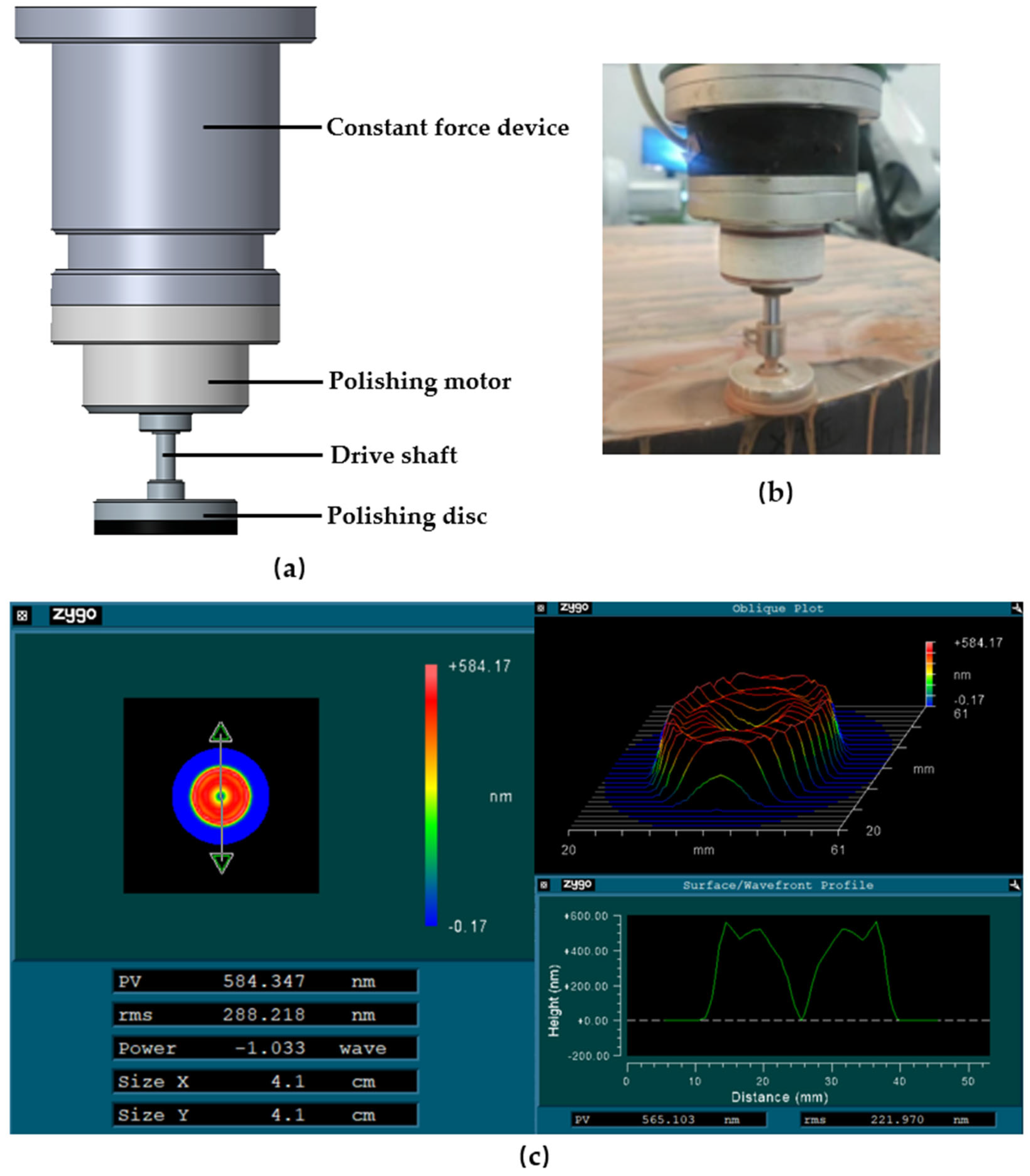
Figure 1, is the earliest polishing tool applied in the computer-controlled optical surfacing technology. It has the advantages of a simple structural form, easy implementation, and a large polishing contact area. It is still commonly used in optical mirror polishing nowadays. However, the TIF of the single-rotation small tool polishing device is annular, deviating from the ideal Gaussian shape. After polishing, it is prone to leaving medium-frequency errors, resulting in lower polishing accuracy.
According to the Preston equation, the velocity distribution and pressure distribution of the polishing tool are the main factors that determine the form of the TIF. The distribution of the contact pressure is related to the way the polishing pressure is applied. For a single-rotating small tool polishing device, its polishing pressure is applied to the polishing disk at a single point through the pressure output shaft. Meanwhile, the pressure output shaft is also the driving shaft for the rotation movement of the polishing disk, meaning that the pressure application point coincides with the center of the rotation movement. According to the eccentric compression theory [
19], the contact pressure distributions generated by different positions of the pressure application point are different. On this basis, the contact pressure distribution can be changed by altering the position of the polishing pressure application point. However, the size of the object discussed in the eccentric compression theory is much larger than that of the polishing disk and is not very precise. To more accurately describe the influence of the position of the pressure application point on the contact pressure distribution, this paper opts to establish a contact pressure analysis model based on the finite element method. We utilized the ABAQUS software version 2020 to model the contact pressure. Subsequently, the Matlab software version 2020b was employed to post-process the calculation results from the ABAQUS software. With Matlab, we completed the modeling and analysis of the removal function. The modeling parameters are shown in
Table 1. The settings of the boundary conditions in the model are as follows. We fixed all six degrees of freedom of the workpiece and established a contact relationship between its upper surface and the lower surface of the asphalt layer. A coupling constraint was established between the upper surface of the Pitch layer and the lower surface of the Metal disks. We applied a pressure of 20N on the pressure output shaft and established a contact relationship between the lower endpoint of the pressure output shaft and the upper surface of the Metal disks. The established finite element analysis model is shown in
Figure 2.
As shown in
Figure 2, in order to explore the influence of the pressure application point on the pressure distribution, we first established a finite element analysis model in which the pressure application point coincides with the selected center of the polishing disk. On this basis, we moved the pressure output shaft to deviate from the center of the polishing disk (the center of the polishing rotation movement), defined the deviation distance as E, and defined the diameter of polishing disk as D. We analyzed the contact pressure distribution when the pressure application point coincides with the center of the polishing disk (E = 0 mm), and also analyzed the contact pressure distribution when the pressure application point is separated from the center of the polishing disk (E ≠ 0 mm). The analysis results are shown in
Figure 3.
According to the simulation results of the pressure distribution in
Figure 3, the following can be known: when E = 0 mm, that is, when the pressure application point coincides with the center of the polishing disk, the peak value of the contact pressure is located at the pressure application point, and the pressure distribution gradually decreases towards the outside in a quasi-Gaussian shape. When E ≠ 0 mm, that is, when the pressure application point does not coincide with the center of the polishing disk, the pressure peak point deviates from the center of the polishing disk following the pressure application point and moves in the X+ direction. Meanwhile, with the increase in the moving distance, the overturning moment on the polishing disk increases, and the pressure distribution in some contact areas in the X-direction gradually decreases or even disappears.
In order to further analyze the influence of the position of the pressure application point on the form of the TIF, we obtained the polishing speed distribution V within the contact area according to Equation (3), as shown in
Figure 4.
where
represents the magnitude of the velocity value at any contact point within the contact area between the polishing disk and the polished element, ω represents the rotational speed of the polishing disk, and
represents the distance of this point relative to the center of rotation.
On the premise of knowing the pressure distribution and velocity distribution, we obtained the TIF at different positions of the pressure application point through the Preston equation, as shown in
Figure 5. Meanwhile, in order to compare the morphological differences in the TIFs at different positions of the pressure application point more intuitively, we intercepted the cross-sections of the TIF in the X-direction, normalized each cross-section, and then carried out a comparative analysis. The results are shown in
Figure 6.
It can be seen from
Figure 5 and
Figure 6 that as the pressure application point deviates from the center of the polishing disk and moves in the X+ direction, the removal amount in the X- direction gradually decreases, while the removal amount in the X+ direction gradually increases. The TIF gradually changes from an annular shape to a quasi-Gaussian shape with a single peak. When E =
D, the removal amount of the TIF in the second and third quadrant regions has been reduced to a negligible level. However, from the perspective of engineering implementation, applying polishing pressure with a deviation of 7.5 mm from the center on a polishing disk with a diameter of 30 mm will lead to insufficient stability of the polishing disk, causing obvious vibrations during the polishing process. When E =
D, the difference between the removal amount of the TIF in the second and third quadrant regions and that in the first and fourth quadrant regions is already quite significant. The TIF is also of the quasi-Gaussian type with a single peak. Considering both the engineering implementation and the optimization effect, we will subsequently take the TIF with E =
D as the research object to carry out research work such as simulation polishing and TIF experiments.
2.3. Comparison of Simulation Polishing
In order to explore the difference in the surface shape correction capabilities between the optimized TIF (E =
D, D = 30 mm) and the traditional TIF (E = 0 mm, D = 30 mm), based on the self-developed process calculation software, we carried out simulation machining calculations on the same surface shape error using the above two TIFs, respectively. The selected surface shape error and simulation machining results are shown in
Figure 7. Meanwhile, we also analyzed the PV convergence rate and RMS convergence rate after machining with the two TIFs. For details, please refer to
Table 2.
It can be seen from the machining results that compared with the TIF when E = 0 mm, D = 30 mm, the PV convergence rate of the TIF when E = D, D = 30 mm is increased by 32.527%, and the RMS convergence rate is increased by 33.560%. The optimization effect is obvious.
3. Eccentric Pressured Small Tool Polishing Device
Based solely on simulation analysis, we have preliminarily verified the effectiveness of optimizing the TIF morphology by changing the position of the polishing pressure application point to improve the convergence efficiency and convergence accuracy of the surface shape. In order to implement this optimization method and conduct further verification, we have designed a new type of small tool polishing device that can separate the pressure application point from the rotation center of the polishing disk. We named it the eccentric pressured small tool polishing device. Moreover, we applied this device to our robotic polishing system and completed the subsequent TIF experiments and aspheric mirror processing experiments.
3.1. Components of Eccentric Pressured Small Tool Polishing Device
The overall view of the eccentric pressured small tool polishing device is shown in
Figure 8. This device consists of a constant force device, a polishing grinder, a pressure application point position controller, bearings, and a polishing disk. Different from the traditional single-rotation small tool polishing device, we have added a pressure application point position controller below the motor. Through the separation of the pressure application shaft and the rotation drive shaft, the polishing pressure application point no longer coincides with the rotation center of the polishing disk, and at the same time, the active control of the position of the pressure application point can also be achieved.
To achieve the above effects, the pressure application point position controller incorporates a pressure output shaft, a pressure output shaft guide rail, and a motor that drives the pressure output shaft to move along the guide rail. The positioning accuracy of the pressure application point position is ±0.05 mm. It can precisely adjust the position of the pressure application point based on the control signals from the computer system. In addition, we have also improved the structure of the polishing disk. Bearings, specifically crossed roller bearings, as well as a metal adapter plate, have been added to the polishing disk to ensure that it maintains a stable eccentric compression state during the rotation process.
3.2. The Application of the Eccentric Compression Small Tool Polishing Device
As shown in
Figure 9, the eccentric pressured small tool polishing device is installed on the robotic polishing system. The robotic polishing system consists of three major parts: an industrial robot, a polishing actuator, and a processing platform. Among them, the model of the industrial robot is the ABB industrial robot IRB6640. Its maximum working range can reach 2500 mm, the maximum load is 180 kg, the repeat positioning accuracy is 0.07 mm, and the repeat path accuracy is 0.7 mm. This robot is equipped with a six-axis linkage system and is able to cover any point on the surface of the workpiece to be processed. In this way, it can ensure the trimming and polishing of the workpiece surface.
4. Experiments
4.1. TIF Experiment
To verify the effectiveness of optimizing the TIF by means of the eccentric compression method, we conducted TIF experiments on JGS2 glass using the eccentric pressured small tool polishing device installed on the robotic polishing system.
Experimental steps: (1) Select a piece of JGS2 glass with good flatness, mark the coordinate directions, and use an interferometer to detect the initial surface shape of the JGS2 glass. (2) Use the industrial robot to drive the new polishing device to conduct fixed-point polishing at the center of the glass, and then measure the surface shape after polishing. (3) Subtract the two surface shapes to obtain the actual TIF. The experimental parameters are shown in
Table 3. For the first four parameters, we have selected the values that are consistent with those in the TIF modeling. In addition, we have adopted the rotating speed and the types of polishing powder that are commonly used in our engineering practice.
In order to facilitate obtaining the shape of the TIF and considering the removal efficiency, the polishing time is set to 60 s. During the experiment, the temperature was maintained at 24 ± 0.5 °C, and the humidity was controlled within 50 ± 5%. The experimental results are shown in
Figure 10 and
Figure 11.
Figure 11 normalizes the theoretical and experimental TIF. It can be seen from
Figure 7 that the theoretical results are in good agreement with the experimental ones, which proves the correctness of the theoretical model. However, there are still slight differences between the theoretical results and the actual results. One possible reason is that during the modeling process, the asphalt in the polishing disk was approximated as an elastic body, so there are still some differences between the experimental TIF and the theoretical TIF. If the viscoelastic properties of asphalt could be introduced into the model, the degree of conformity between the experimental TIF and the theoretical TIF would be further enhanced. In addition, factors not taken into account in the theoretical model, such as the influence of environmental factors and measurement errors during the experiment, have an impact on the accuracy of the theoretical model.
4.2. Aspheric Surface Processing Experiment
To further verify the polishing performance of the optimized TIF, we selected a piece of JGS2 glass with a diameter of 230 mm and carried out aspheric surface processing experiments. The objective of the experiment is to process the spherical surface with a curvature radius of 4000 mm on the quartz into an off-axis parabolic surface with an off-axis amount of 170 mm, as well as to make the RMS value of the surface error converge to below 10 nm.
The processing steps are as follows: (1) Mark the direction of the spherical surface and use an interferometer to detect the error compared with that of the target off-axis parabolic surface, which will be taken as the initial form error. (2) Use the dwell time algorithm based on the matrix method to calculate the polishing dwell time. (3) Calculate the running speed of the robot according to the processing path and the dwell time, and then carry out the processing. (4) Detect the error between the processed surface and the target off-axis parabolic surface. If the RMS of the error is less than 10 nm, the processing is completed. If it fails to meet the requirements, continue with the next round of processing.
In order to exclude the influence of the edge effect, only the error within the area with a diameter of 200 mm is detected. The processing parameters are shown in
Table 4, and the processing status is shown in
Figure 12. The selection of parameters remains consistent with that in TIF modeling and experiments. The polishing trajectory is of the type commonly used in polishing engineering. During the experiment, the temperature was maintained at 24 ± 0.5 °C, and the humidity was controlled within 50 ± 5%. The surface shape measurement equipment used was the Zygo Verifire interferometer, and the detection method was the null point interferometry. We used the Zygo Mx analysis software version 6.3.0.4 to display the surface shape data of the initial surface and that was measured after three rounds of processing.
The results of the aspheric surface processing experiment are as follows: After three rounds of processing, the value of PV of the surface error converged from 1861.180 nm to 64.875 nm, and the value of RMS converged from 299.857 nm to 6.043 nm, achieving the goal. The initial form error and the error after three rounds of processing are shown in
Figure 13. The convergence efficiencies of PV and RMS values after each round of processing are shown in
Table 5. In order to exclude the influence of the edge effect, only the error within the area with a diameter of 200 mm is detected. The processing parameters are shown in
Table 4, and the processing status is shown in
Figure 12.
It can be seen from
Figure 13 and
Table 5 that the initial surface form is of a low-frequency type. For low-frequency surface form error when processed using the eccentric pressured small tool polishing device, the actual convergence efficiencies of PV and RMS have reached over 80%. For the medium-frequency surface form error remaining after the first and second rounds of processing, the actual convergence efficiency of PV is higher than 55%, and that of RMS is higher than 60%, which is very close to the performance in the simulation experiment. After three rounds of processing, the value of PV converged to 64.875 nm, and the value of RMS converged to 6.043 nm. The polishing precision has reached a level comparable to that of the magnetorheological polishing device and the ion beam polishing device.
5. Discussion
This paper proposes an eccentric pressured small tool polishing device. By changing the polishing pressure distribution, the shape of the TIF is optimized. By changing the position of the pressure application point, the polishing pressure distribution is altered, and then a Gaussian-like TIF of the disk-shaped small tool is obtained under the single rotation motion mode. We have completed the processing of high-precision off-axis aspheric surfaces using the eccentric pressured small tool polishing device. The results show that the optimized TIF has achieved significant improvements in both convergence efficiency and convergence accuracy. Compared with the planetary motion small tool polishing device, the eccentric pressured small tool polishing device proposed in this paper has a more compact structure. The movement of the device during the processing will not affect the shape of the TIF. The actual TIF of the device at different positions on the processed surface remains consistent with the theoretical TIF. The residual errors after processing are smaller, and higher surface figure accuracy can be achieved. If it is combined with the ion beam polishing device, it is expected to significantly reduce the difficulty of obtaining ultra-high-precision optical components with an RMS value of less than 1 nm.
Furthermore, if the shape of the TIF can be changed in real time during the processing, more benefits will be brought. Firstly, in the process of calculating the dwell time, new calculation degrees of freedom can be added, which is expected to further improve the surface figure convergence efficiency and convergence accuracy. Secondly, it is more conducive to suppressing the edge effect existing in the polishing process. When the polishing disk does not move too far out of the mirror surface, the position of the polishing pressure application point can be changed to shift the peak of the TIF towards the edge so as to remove the edge warping caused by the edge effect. In the future, we will continue to carry out more research work focusing on the active control of the shape of the TIF.
6. Conclusions
In view of the deficiencies of the existing small tool polishing devices, this paper proposes a method to optimize the shape of the TIF based on the control of the polishing pressure distribution. That is, under the single rotation mode, the polishing pressure application point is separated from the rotation axis. By changing the position of the polishing pressure application point, the shape of the TIF is optimized. Moreover, an eccentric pressured small tool polishing device that can realize the above optimization method has been designed. Based on the finite element method, this paper establishes a contact pressure distribution model, analyzes the influence of different positions of the pressure application point on the contact pressure distribution, determines the position of the pressure application point that makes the TIF close to the Gaussian shape, and conducts a comparative simulation processing experiment. Compared with the TIF before optimization (E = 0 mm, D = 30 mm), the optimized TIF (E = D, D = 30 mm) has an increase of 32.527% in the PV convergence rate and an increase of 33.560% in the RMS convergence rate, demonstrating a significant optimization effect. On this basis, we obtained the optimized actual TIF using the eccentric pressured small tool polishing device. The shape and distribution of the actual TIF tend to be consistent with those of the theoretical TIF, which verifies the accuracy of the analysis model. Furthermore, we carried out an aspheric surface processing experiment. After three rounds of processing, the value of PV converged from 1861.180 nm to 64.875 nm, and the value of RMS converged from 299.857 nm to 6.043 nm. For the medium-frequency surface form, the actual convergence efficiency of PV is higher than 55%, and that of RMS is higher than 60%, which is close to the performance in the simulation experiment, verifying the feasibility and effectiveness of this optimization method.
Author Contributions
Conceptualization, Q.L. and Z.M.; methodology, Y.Y.; software, Q.L.; validation, X.J., Y.Y. and Z.M.; formal analysis, J.D.; investigation, Q.L.; data curation, Q.L.; writing—original draft preparation, Q.L.; writing—review and editing, X.J.; supervision, Z.M.; project administration, Q.L.; funding acquisition, J.D. All authors have read and agreed to the published version of the manuscript.
Funding
This research received no external funding.
Institutional Review Board Statement
Not applicable.
Informed Consent Statement
Not applicable.
Data Availability Statement
The data presented in this study are available on request from the corresponding author.
Acknowledgments
We are very grateful for Geng-Qi’s help in aspheric surface polishing.
Conflicts of Interest
The authors declare no conflicts of interest.
References
- Jones, R.A. Computer-controlled optical surfacing with orbital tool motion. Opt. Eng. 1986, 25, 780–790. [Google Scholar] [CrossRef]
- Kim, D.; Park, W.; Kim, S.; Burge, J. Parametric modeling of edge effects for polishing tool influence functions. Opt. Express 2009, 17, 5656–5665. [Google Scholar] [PubMed]
- Walker, D.; Brooks, D.; King, A.; Freeman, R.; Morton, R.; McCavana, G.; Kim, S. The ‘Precessions’ tooling for polishing and figuring flat, spherical and aspheric surfaces. Opt. Express 2003, 11, 958–964. [Google Scholar] [CrossRef] [PubMed]
- Kim, D.W.; Kim, S.W. Static tool influence function for fabrication simulation of hexagonal mirror segments for extremely large telescopes. Opt. Express 2005, 13, 910–917. [Google Scholar] [CrossRef] [PubMed]
- Tam, H.; Cheng, H. An investigation of the effects of the tool path on the removal of material in polishing. J. Mater. Process. Technol. 2010, 210, 807–818. [Google Scholar] [CrossRef]
- Zhong, B.; Huang, H.; Chen, X.; Deng, W.; Wang, J. Modelling and simulation of mid-spatial-frequency error generation in CCOS. J. Eur. Opt. Soc.-Rapid Publ. 2018, 14, 1–13. [Google Scholar] [CrossRef]
- Yao, Y.; Ma, Z.; Xu, L.; Ding, J.; Wang, Y.; Shen, L.; Jiang, B. Removal functions of different polishing heads worked in planet motion model. Opt. Precis. Eng. 2017, 25, 2706–2713. [Google Scholar]
- Suratwala, T.; Menapace, J.; Tham, G.; Steele, R.; Wong, L.; Ray, N.; Bauman, B. Understanding and reducing mid-spatial frequency ripples during hemispherical sub-aperture tool glass polishing. Appl. Opt. 2022, 61, 3084–3095. [Google Scholar] [CrossRef] [PubMed]
- Liu, H.; Zhai, A.; Xu, K. Configuration synthesis method of planetary polishing device based on AKC. Chin. J. Eng. Des. 2020, 27, 19–26. [Google Scholar]
- Zhang, L.; Wan, S.; Li, H.; Guo, H.; Wei, C.; Zhang, D. Modeling and in-depth analysis of the mid-spatial-frequency error influenced by actual contact pressure distribution in sub-aperture polishing. Opt. Express 2023, 31, 14414–14431. [Google Scholar] [CrossRef] [PubMed]
- Kordonski, W.I.; Jacobs, S.D. Magnetorheological finishing. Int. J. Mod. Phys. B 1996, 10, 2837–2848. [Google Scholar] [CrossRef]
- Chunlin, M.; Lambropoulos, J.C.; Jacobs, S.D. Process parameter effects on material removal in magnetorheological finishing of borosilicate glass. Appl. Opt. 2010, 49, 1951–1963. [Google Scholar]
- Ren, K.; Luo, X.; Zheng, L.; Bai, Y.; Li, L.; Hu, H.; Zhang, X. Belt-MRF for large aperture mirrors. Opt. Express 2014, 22, 19262–19276. [Google Scholar] [CrossRef] [PubMed]
- Drueding, T.; Bifano, T.; Fawcett, S. Contouring algorithm for ion figuring. Precis. Eng. 1995, 17, 10–21. [Google Scholar] [CrossRef]
- Liao, W.; Dai, Y.; Xie, X.; Zhou, L. Microscopic morphology evolution during ion beam smoothing of Zerodur® surface. Opt. Express 2014, 22, 377–386. [Google Scholar] [CrossRef] [PubMed]
- Preston, F. The theory and design of plate glass polishing machines. J. Soc. Glass Technol. 1927, 11, 214–256. [Google Scholar]
- Li, A. Research on Removal Characteristics and Process of Computer-Controlled Small Tool Lapping and Polishing. Master’s Thesis, National University of Defense Technology, Changsha, China, 2003. [Google Scholar]
- Zheng, W. Research on Automatic Forming of High-Steepness Optical Aspheric Surfaces. Master’s Thesis, Zhejiang University, Hangzhou, China, 1998. [Google Scholar]
- You, L.; Ma, Y.; Li, Z. Design on biaxial eccentric compression of rectangular foundation. Shanxi Archit. 2011, 37, 60–62. [Google Scholar]
Figure 1.
The single-rotation small tool polishing device and its TIF. (a) Schematic diagram of the single-rotation small tool polishing device. (b) Actual processing situation of the single-rotation small tool polishing device. (c) TIF of the single-rotation small tool polishing device.
Figure 1.
The single-rotation small tool polishing device and its TIF. (a) Schematic diagram of the single-rotation small tool polishing device. (b) Actual processing situation of the single-rotation small tool polishing device. (c) TIF of the single-rotation small tool polishing device.
Figure 2.
Finite element analysis model. (a) Composition of the finite element analysis model. (b) Model with the pressure application point coinciding with the selected center of the polishing disk. (c) Model with the pressure application point separated from the rotation center of the polishing disk.
Figure 3.
Results of contact pressure analysis. (a) Pressure distribution when E = 0 mm. (b) Pressure distribution when E = 2.5 mm (D, D = 30 mm). (c) Pressure distribution when E = 5 mm (D). (d) Pressure distribution when E = 7.5 mm (D).
Figure 3.
Results of contact pressure analysis. (a) Pressure distribution when E = 0 mm. (b) Pressure distribution when E = 2.5 mm (D, D = 30 mm). (c) Pressure distribution when E = 5 mm (D). (d) Pressure distribution when E = 7.5 mm (D).
Figure 4.
Normalized velocity distribution in the contact area of 30 mm diameter polishing disk (ω = 1 rps).
Figure 4.
Normalized velocity distribution in the contact area of 30 mm diameter polishing disk (ω = 1 rps).
Figure 5.
TIFs at different positions of the pressure application point. (a) TIF when E = 0 mm; (b) TIF when E = 2.5 mm (D); (c) TIF when E = 5 mm (D); (d) TIF when E = 7.5 mm (D).
Figure 5.
TIFs at different positions of the pressure application point. (a) TIF when E = 0 mm; (b) TIF when E = 2.5 mm (D); (c) TIF when E = 5 mm (D); (d) TIF when E = 7.5 mm (D).
Figure 6.
Comparative analysis of the cross-sections of the TIF on the X-axis.
Figure 6.
Comparative analysis of the cross-sections of the TIF on the X-axis.
Figure 7.
Surface shape errors and simulation machining results. (a) Surface shape errors. (b) Simulation machining residuals (E = 0 mm, D = 30 mm). (c) Simulation machining residuals (E = D, D = 30 mm).
Figure 7.
Surface shape errors and simulation machining results. (a) Surface shape errors. (b) Simulation machining residuals (E = 0 mm, D = 30 mm). (c) Simulation machining residuals (E = D, D = 30 mm).
Figure 8.
Schematic diagram of the eccentric pressured small tool polishing device.
Figure 8.
Schematic diagram of the eccentric pressured small tool polishing device.
Figure 9.
Schematic diagram of the robot polishing system.
Figure 9.
Schematic diagram of the robot polishing system.
Figure 10.
Two-dimensional and 3D shapes of the experimental TIF. We used the Zygo Mx analysis software version 6.3.0.4 to display 2D and 3D shapes of the experimental TIF.
Figure 10.
Two-dimensional and 3D shapes of the experimental TIF. We used the Zygo Mx analysis software version 6.3.0.4 to display 2D and 3D shapes of the experimental TIF.
Figure 11.
Comparison between the experimental TIF and the theoretical TIF. (a) Section profile in the X-direction, (b) section profile cross-peak point and parallel to the y-direction.
Figure 11.
Comparison between the experimental TIF and the theoretical TIF. (a) Section profile in the X-direction, (b) section profile cross-peak point and parallel to the y-direction.
Figure 12.
Processing status of Eccentric pressured small tool polishing device.
Figure 12.
Processing status of Eccentric pressured small tool polishing device.
Figure 13.
Initial surface form error map and surface form error maps after processing. (a) Initial surface form error map. (b) Surface form error map after first round processing. (c) Surface form error map after second round processing. (d) Surface form error map after third round processing.
Figure 13.
Initial surface form error map and surface form error maps after processing. (a) Initial surface form error map. (b) Surface form error map after first round processing. (c) Surface form error map after second round processing. (d) Surface form error map after third round processing.
Table 1.
Modeling parameters.
Table 1.
Modeling parameters.
| Parameters | Pressure Output Shaft | Metal Disks | Pitch Layer | Workpiece |
|---|
| Material | Stainless Steel | Aluminum alloy | Pitch | JGS2 |
| Young modulus | 193 GPa | 72 GPa | 0.23 GPa | 74 GPa |
| Poisson radio | 0.28 | 0.33 | 0.40 | 0.17 |
| Density | 7.93 g/cm3 | 2.75 g/cm3 | 1.20 g/cm3 | 2.2 g/cm3 |
| Size | Φ8 × 20 mm | Φ30 × 8 mm | Φ30 × 2 mm | 50 × 50 × 20 mm |
| Mesh type | C3D8R | C3D8R | C3D8R | C3D8R |
| Mesh size | 0.5 mm | 0.5 mm | 0.5 mm | 1 mm |
Table 2.
Comparison table of Convergence efficiency.
Table 2.
Comparison table of Convergence efficiency.
| TIF | E = 0 mm | E = 5 mm |
|---|
| PV convergence rate | 45.124% | 77.651% |
| RMS convergence rate | 43.710% | 77.270% |
Table 3.
Parameters of the TIF experiment.
Table 3.
Parameters of the TIF experiment.
| Parameters | Values |
|---|
| Diameter of polishing disk (mm) | 30 |
| Eccentric distance (mm) | 5 |
| Eccentric direction | X+ |
| Polishing pressure (N) | 20 |
| Rotating speed (rps) | 3 |
| Polishing time (s) | 60 |
| Polishing powder | Cerium oxide |
| Workpiece material | JGS2 |
Table 4.
Parameters of the processing experiment.
Table 4.
Parameters of the processing experiment.
| Parameters | Values |
|---|
| Diameter of polishing disc (mm) | 30 |
| Eccentric distance (mm) | 5 |
| Eccentric direction | X+ |
| Polishing pressure (N) | 20 |
| Rotating speed (rps) | 3 |
| Polishing powder | Cerium oxide |
| Workpiece material | JGS2 |
| The type of trajectory | Raster type |
Table 5.
Summary table of convergence efficiency.
Table 5.
Summary table of convergence efficiency.
| Processing Rounds | Round 1 | Round 2 | Round 3 |
|---|
| PV convergence rate | 80.260% | 56.653% | 59.263% |
| RMS convergence rate | 81.128% | 70.543% | 63.747% |
| Disclaimer/Publisher’s Note: The statements, opinions and data contained in all publications are solely those of the individual author(s) and contributor(s) and not of MDPI and/or the editor(s). MDPI and/or the editor(s) disclaim responsibility for any injury to people or property resulting from any ideas, methods, instructions or products referred to in the content. |
© 2025 by the authors. Licensee MDPI, Basel, Switzerland. This article is an open access article distributed under the terms and conditions of the Creative Commons Attribution (CC BY) license (https://creativecommons.org/licenses/by/4.0/).


