Abstract
With the increasing demand for various autonomous driving services in urban environments, low-speed autonomous vehicles, such as autonomous shuttles and purpose-built vehicles, equipped with enhanced driving characteristics suitable for urban roads featuring narrow streets, intersections, congested traffic, and small radii, are emerging. In particular, the 4WS (four-wheel steering) system, which is being integrated into these vehicles, is designed to steer both the front and rear wheels. This system improves steering responsiveness and stability, providing maneuverability under various driving conditions and making it highly suitable for urban environments. However, the 4WS system involves complex dynamic modeling and poses challenges in designing a path tracker, especially if factors such as the vehicle’s turning radius and road curvature are not properly considered. To address these challenges, this paper proposes a path tracker for a low-speed autonomous driving system based on a 4WS system, optimized for the characteristics of urban roads to minimize the vehicle’s turning radius and enhance driving performance. The proposed path tracker independently controls the front and rear wheels and incorporates road curvature and vehicle turning radius as feedforward terms to improve the response performance of the path tracker. The performance of the proposed path tracker was evaluated through simulations and real-car experiments.
1. Introduction
Since the Fourth Industrial Revolution was discussed at the Davos Forum in Switzerland in 2016, there has been increasing interest in autonomous vehicles. Particularly in urban areas, low-speed autonomous shuttles, which offer advantages in terms of safety and convenience, are being developed and deployed as alternative means of transportation to traditional buses and passenger cars [1,2]. Autonomous shuttle services aim to replace private vehicles and public transportation to address the transit needs of urban commuters by supporting the connection of short transit nodes that appear in typical mobility patterns, known as the first mile or last mile. This reduces urban congestion and parking problems caused by unnecessary private vehicle usage through shared mobility solutions.
Moreover, low-speed autonomous shuttles provide an opportunity for cities to reduce congestion and carbon emissions, thus contributing to net-zero targets and many of the United Nations’ Sustainable Development Goals. Designed for operation on predefined routes in low-speed environments, they are often used in commercial, business, or university campuses [3]. A similar eco-friendly transportation option in urban areas is the tram. However, installing rails on the ground incurs infrastructure costs, and in existing narrow road sections, it can lead to severe traffic congestion.
These autonomous shuttles, depending on their intended purpose, must accommodate either a large number of passengers or provide services that require ample space and thus typically have a longer overall length and width compared to conventional vehicles. To ensure the stable operation of such shuttles on urban roads, driving control technology that allows a small turning radius, suited for the characteristics of urban roads, is required [4,5]. A small turning radius and the ability to reliably follow a path are essential for driving irregular urban road sections [6,7,8].
Recently, to improve urban driving performance, many companies have been adopting four-wheel steering (4WS) systems, which aim to enhance the lateral driving performance of vehicles by steering the front and rear wheels independently [6,7]. In the past, 4WS systems were introduced in some high-end vehicles during the 1980s and 1990s. However, due to high costs and complex structures, their commercialization was limited. Recently, advancements in electronic control technology, along with the integration of 4WS with autonomous driving and electric vehicle technologies, have brought renewed attention to this system. In particular, by combining 4WS with electric vehicles’ e-corner modules and independent driving technology, vehicle maneuverability can be maximized, offering significant advantages for urban driving, automated parking, and off-road driving [9]. Additionally, 4WS enables the implementation of innovative steering modes such as crab walking, zero turning, and axis rotation, making it a promising technology for next-generation mobility solutions. These vehicles leverage 4WS technology to enhance steering performance, improving both driving safety and driver convenience. In particular, improvements in driving dynamics through 4WS not only enhance high-speed driving stability but also maximize parking and turning maneuverability in tight spaces, establishing it as a crucial and practical technology.
The path trackers that can be applied to 4WS-based autonomous vehicles can be divided into two categories. One is geometry-based, which mainly includes pure pursuit, the Stanley method, etc. [10]. These methods exploit geometric relationships between the vehicle and the path and are often used for low-speed automated driving systems with good interpretability and fast calculation speed [10,11]. The trade-off between stability and tracking performance is difficult to balance with the pure pursuit method, which ignores the curvature of the path [11]. In general, the Stanley method outperforms pure pursuit in most scenarios. In contrast to pure pursuit, the Stanley method will not “cut corners” but rather overshoots turns [11]. The others are model-based, represented by state-feedback control (SFC), linear quadratic regulator (LQR), and model predictive control (MPC). Model-based methods mainly based on dynamic models are often used for stability control of high-speed vehicles, whose disadvantages include poor real-time performance and difficulty in obtaining kinetic parameters accurately [10].
In this paper, we adopt the Stanley method, which provides balance stability, real-time feasibility, and tracking accuracy, modified for low-speed 4WS vehicles. The proposed path tracker is designed to have low computational complexity by utilizing geometric relationships between vehicle and reference path suitable for low-speed driving instead of a dynamic model [12]. It improves response performance by applying the geometric error relationship between the vehicle and the path, as well as the curvature of the driving path and the vehicle’s turning radius, as correction parameters. To evaluate the performance of the proposed path tracker, simulations and real-car-based performance tests were conducted, demonstrating the validity of the results.
2. 4WS Vehicle Model
In this paper, the 4WS system is used to improve the path-tracking performance of low-speed autonomous vehicles. While previous studies utilizing four-wheel steering systems have primarily focused on enhancing vehicle stability in high-speed driving environments, requiring vehicle dynamic parameter values, this paper employs a kinematic model of the vehicle, as it is necessary to analyze the system in a low-speed driving environment [9,10,11,12].
4WS-Based Kinematic Vehicle Model
There are two commonly used methods for modeling the dynamic characteristics of a vehicle. One approach models the vehicle as a bicycle using only two wheels, and the other models it using all four wheels. In this study, simulations were conducted using a simplified bicycle model that considers only two wheels, based on a 4WS-based kinematic vehicle model [13,14,15,16,17,18]. A common simplification of an Ackerman-steered vehicle used for geometric path tracking is the bicycle model. For the purpose of geometric path tracking, it is only necessary to state that the bicycle model simplifies the 4WS-based car by combining the two front wheels and the two rear wheels to form a two-wheeled model, like a bicycle [11]. Most studies on path trackers based on geometric, kinematic, and dynamic models adopt the bicycle model [4,5,8,12].
Figure 1 illustrates the kinematic bicycle model of a four-wheel steering vehicle, where the steering angles of the front and rear wheels differ. The primary assumption in developing the kinematic model is that the velocity vectors at each wheel align with the respective steering angles. Specifically, the velocity vector at the front wheel forms an angle, , with the vehicle’s longitudinal axis, while the velocity vector at the rear wheel forms an angle . This assumption is equivalent to considering the slip angles at both wheels as zero, which is reasonable for low-speed (<5 [m/s]) vehicle motion, where the lateral forces generated by the tires remain minimal [19]. Also, the bicycle model is assumed to perform rigid body motion on a fixed X–Y coordinate plane, with no wheel slip. Point C represents the vehicle’s center of gravity, and this point indicates the position of the vehicle in the fixed X–Y coordinate system.
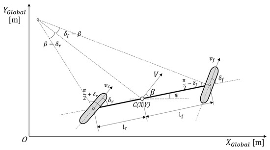
Figure 1.
4WS-based on kinematic vehicle model.
The vector, , represents the linear velocity vector of the vehicle at its center of gravity. and represent the front-wheel steering angle and the rear-wheel steering angle of the vehicle, respectively. denotes the vehicle’s heading angle, and represents the side-slip angle, which is the angle between the vehicle’s longitudinal axis and the linear velocity vector at the vehicle’s center of gravity. and represent the linear velocity vectors of the front and rear wheels of the bicycle model, respectively. is the distance from the vehicle’s center of gravity to the front axle, and is the distance from the center of gravity to the rear axle. The kinematic equations representing these relationships are shown in Equations (1)–(5). The equations below represent the velocity in the X direction in the global coordinate system, the velocity in the Y direction in the global coordinate system, the rate of change of the heading angle in the vehicle coordinate system, the side-slip angle in the vehicle coordinate system, and the velocity in the vehicle coordinate system, respectively.
3. Path-Tracker Design
Autonomous vehicles require a path-tracking control algorithm to implement the driving strategies derived from the perception and decision-making components of the autonomous driving system [20,21]. The previously mentioned path-tracking control algorithm is also called a path tracker. Path trackers are generally classified into geometry-based, kinematics-based, and dynamics-based algorithms. The geometric path-tracking algorithm is designed to control the lateral movement of the vehicle based on the geometric relationship between the vehicle and the path. In this study, since the focus was on a low-speed environment, which is less affected by vehicle dynamic characteristics, a simpler geometry-based algorithm was used compared to other types of path trackers.
3.1. Stanley Method
The Stanley method is a path-tracking control algorithm used by Stanford University’s autonomous vehicle, Stanley, during the 2005 DARPA Grand Challenge. As shown in Figure 2, this algorithm is geometry-based and uses the lateral distance error between the center of the vehicle’s front axle and the nearest path point as a nonlinear feedback function to reduce the lateral deviation. Additionally, the steering angle, , is designed to converge to the heading angle, , of the reference path. The Stanley method can be expressed by Equations (6) and (7) [11].
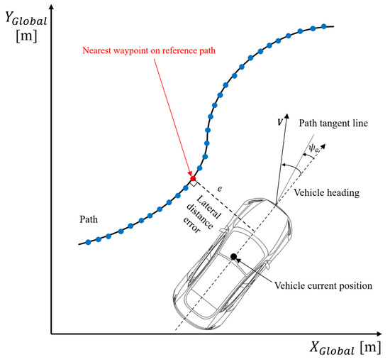
Figure 2.
Schematic diagram of the Stanley method.
In Equation (6), represents the vehicle’s heading angle, and represents the heading angle of the path, with the difference between these values indicating the heading angle error . In Equation (7), the control command, , is generated to control the vehicle by considering the heading angle error, , of the vehicle relative to the path, the lateral distance error, , and the longitudinal velocity, of the vehicle. The larger the heading angle error in the first term and the lateral error distance in the second term, the more control command is applied to follow the path. Additionally, is a gain parameter. This control law ensures that as or the lateral distance error, increases, the front wheels steer more aggressively towards the reference path, enhancing trajectory tracking performance. Figure 3 illustrates the overall architecture of the Stanley method.
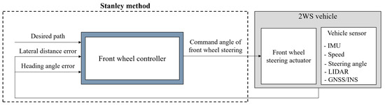
Figure 3.
Architecture of the Stanley method.
In Section 4, the Stanley method is used as a comparison benchmark to verify the performance of the proposed path tracker against conventional 2WS and conventional 4WS. The conventional 2WS operates in the same mechanism described in this chapter. In contrast, the conventional 4WS applies the same front steering angle as in this chapter, but the rear steering angle operates in a counter-phase steering mode, fixed at 30% of the front steering angle.
3.2. Proposed Path Tracker for 4WS Vehicle
We propose a 4WS-based path tracker to improve the path-tracking performance of autonomous vehicles in urban environments with many non-standard sections. Compared to a dynamics-based path tracker, the geometry-based path tracker used in this paper guarantees stable performance in low-speed environments and has the advantage of simpler parameter settings, though it has the drawback of reduced responsiveness to sudden path changes [22,23]. However, in this paper, we aim to overcome the limitations of the existing algorithm by using the characteristics of the 4WS system.
The proposed path tracker for 4WS-based autonomous vehicles generates steering commands and for independent lateral control of the front and rear wheels. Ultimately, the vehicle’s lateral movement is controlled to ensure that the autonomous vehicle follows the target path without deviation [24,25]. The basic control mechanism of the proposed path tracker is shown in Figure 4. The gain parameters of the proposed path tracker presented in this chapter determine the characteristics of the path tracker as described in Table 1. These gain parameters should be tuned considering the characteristics of the path and the driving platform.
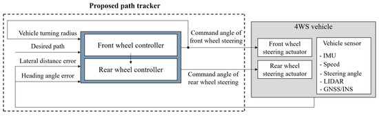
Figure 4.
Architecture of the proposed path tracker.

Table 1.
Description of the gain parameters of the proposed path tracker.
3.2.1. Front Wheel Controller Based on the Curvature of the Reference Path Tracker
The calculation of the front steering angle for path-tracking control utilizes the geometric relationship between the vehicle and the reference path. As shown in Figure 5, the vehicle selects the nearest waypoint from the reference path to determine the target point for path tracking. At this point, the reference point for the vehicle’s current position is selected as the center of the longitudinal axis of the vehicle, taking into account the center of gravity of the vehicle, which was selected as the 4WS vehicle platform for the driving experiments in this study.
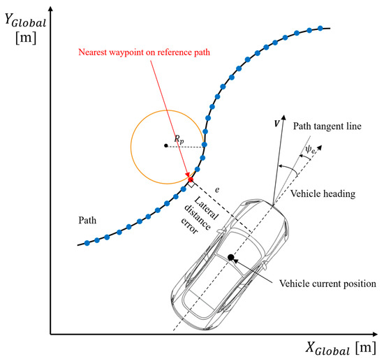
Figure 5.
Schematic diagram of proposed 4WS path tracker.
Based on the selected nearest waypoint, the lateral distance error, between the vehicle and the reference path, as well as the heading angle error, , is calculated [11,26]. Additionally, the curvature, of the reference path is incorporated as a feedforward term to improve the response performance of the path tracker, with the aim of enhancing the vehicle’s path-tracking performance [26]. is the inverse of the road radius, . Equation (8) represents the heading angle error between the vehicle and the path, and Equation (9) calculates the curvature, of the waypoint on the reference path after the nearest waypoint [27,28]. Finally, as shown in Equation (10), the proposed path tracker generates the front steering angle, .
As the heading error, in the first term and the lateral deviation, e, in the second term of Equation (8) increase, a greater control command is applied to follow the path. Additionally, even when the error between the vehicle and the reference path is zero—meaning that the lateral distance error, e, and the heading error, are both zero—the curvature, of the reference path is incorporated as a feedforward term. This allows the vehicle to account for upcoming path information in advance, improving the vehicle’s response performance and leading to better path-tracking accuracy [29].
3.2.2. Rear Wheel Controller Based on Curvature of Vehicle Turning Radius
Vehicles that are 4WS-based have both same-phase and counter-phase steering modes. Same-phase means the front and rear wheels turn in the same direction, while counter-phase means they steer in opposite directions. The rear steering gain, is used not only to limit the rear wheel steering angle but also to determine the steering mode. If this gain value is set to be negative, the vehicle will be operated with counter-phase steering. In evaluation, the rear steering angle, is limited to 30% of the front steering angle, and is set to a negative value to operate in counter-phase. The rear steering angle range was set with reference to the fact that the rear steering angle in production vehicles like the Mercedes-Benz S-Class can operate up to about 10 degrees, ensuring that passengers do not feel a sense of discomfort compared to a traditional 2WS vehicle [30]. Considering this specification, is set to 0.3 so that the steering angle of the rear wheel is approximately 10 degrees as the front wheel angle range of the experimental vehicle is limited to 30 [deg]. As a result, the rear steering angle, is designed to handle the environment where the vehicle is driving at low speeds in a confined space, and it operates in a counter-phase steering mode to ensure superior path-tracking performance in sections with a small turning radius.
The rear steering angle is calculated by taking the front steering angle, , which incorporates the curvature, of the reference path as a feedforward term and adjusting it. To correct this value, the curvature, of the vehicle turning radius, , derived from Ackermann steering geometry as shown in Equation (11), is used as a correction parameter for calculating the rear steering angle. As a result, the vehicle can follow the current turning path without significant deviation. In other words, the curvature of the path, reflected in the front steering angle, is used as a feedforward term for the calculation of the rear steering angle. This improves the response performance of the proposed path tracker, enabling excellent performance when driving in confined spaces.
The rear steering angle of the proposed path tracker is presented in Equation (12).
4. Evaluation
To validate the performance of the proposed path tracker, simulations and real-car experiments were conducted. The performance verification compared the proposed 4WS path tracker (proposed 4WS) with a conventional 2WS path tracker (conventional 2WS), which uses a Stanley method to steer only the front wheels, and a conventional 4WS path tracker (conventional 4WS), which applies 30% of the front steering angle, calculated using the Stanley method, to the rear wheels in counter-phase [11]. The Stanley method was selected as the benchmark control algorithm because it is widely known to outperform pure pursuit among geometric-based path trackers. Furthermore, since this study focuses on low-speed driving, it does not include comparisons with dynamic-based path trackers, which have higher computational costs and rely more on dynamic models. The RMS (root mean square), MAX (maximum) value, and SD (standard deviation) of the absolute result values are extracted as numerical metrics for comparing the performance of each controller, validating the performance of the proposed controller. These additional metrics offer a more detailed representation of the variability in tracking performance across different trials. The SD provides insight into the consistency of the path tracker’s performance, while the max error highlights the worst-case deviations.
4.1. Simulation
4.1.1. Simulation Environment
A simulation was conducted to verify the basic functionality of the 4WS path tracker proposed in this paper. Therefore, a figure-eight course in Figure 6, which is commonly used in path-tracker simulations, was generated using MATLAB R2022b’s Driving Scenario Designer. The course can provide valuable insight into some important characteristics of a path tracker. This course was chosen to illustrate the steady-state characteristics of the path tracker while executing a constant, nonzero curvature path. This course also includes a point with discontinuous curvature where vehicles transition from one circle to another. The response of the path tracker to this discontinuity provides insight into its robustness [11].
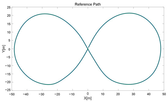
Figure 6.
Reference path for simulation.
Figure 7 shows the simulation architecture, which was implemented using MATLAB R2022b (developed by MathWorks). The plant model of the vehicle for the simulation used the 4WS-based kinematic vehicle model described in “4WS-Based Kinematic Vehicle Model” in Section 2.
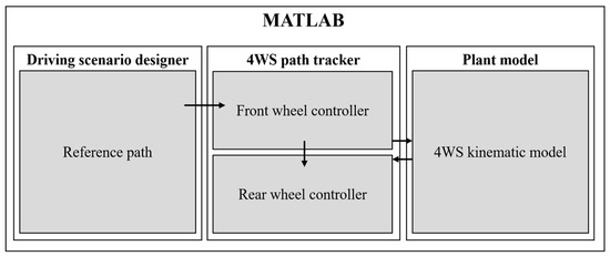
Figure 7.
Simulation architecture based on MATLAB.
The simulation was conducted at a driving speed of 21.6 [KPH], considering the international standardfor Low-Speed Automated Driving (LSAD), which defines the maximum speed for low-speed autonomous driving as 8.89 [m/s] (approximately 32 [KPH]) [3].
4.1.2. Simulation Results
Table 2 comprehensively presents the RMS (root mean square), MAX (maximum) value, and SD (standard deviation) of the absolute result values as the outcome of the simulation verification, comparing the results for each tracker. The graphs for each performance indicator are shown in Figure 8.
Table 2.
Simulation results.
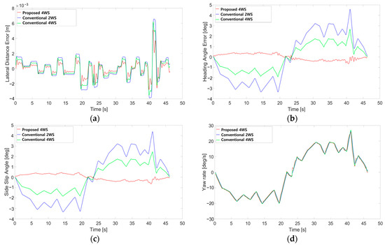
Figure 8.
Simulation results: (a) lateral distance error; (b) heading angle error; (c) side-slip angle; (d) yaw rate.
Based on the RMS results of the lateral deviation and heading angle error, it was confirmed that the proposed path tracker, unlike the conventional 2WS and conventional 4WS path trackers, reflects the vehicle’s turning radius and the curvature of the reference path, thereby improving the path tracker’s response performance and demonstrating excellent path-tracking capabilities. Regarding the RMS of the side slip angle, it was observed that the rear-wheel steering reduced the side-slip angle compared to the other path trackers. The RMS of the yaw rate showed higher values than those of the conventional 2WS path tracker. However, since the environment is primarily low speed, this is not expected to significantly impact vehicle stability. Additionally, similar to the RMS, MAX and SD also tend to decrease in most cases, compared to other path trackers. This demonstrates the higher consistency of the proposed path tracker’s performance.
4.2. Real-Car Experiment
4.2.1. Real-Car Experiment Environment
The reference path for the real-car experiment was designed with both straight and curved sections, as shown in Figure 9, to verify the tracking performance in each section. The driving experiment architecture is shown in Figure 10. The driving experiment environment was built on the Ubuntu 18.04 operating system, and the path tracker was designed using the NDT (Normal Distributions Transform)-based localization algorithm of Autoware, which is an open-source autonomous driving software package, along with ROS (Robot Operating System) in C++ [31,32]. The specifications of the 4WS-based autonomous vehicle platform used for the driving experiment are listed in Table 3, which supports front- and rear-wheel steering, as shown in Figure 11. Lateral control was verified by transmitting the control commands calculated by the proposed path tracker to the vehicle via the CAN (controller area network) communication interface.
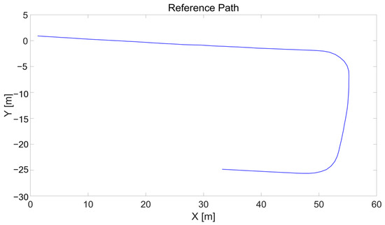
Figure 9.
Reference path for real-car experiment.
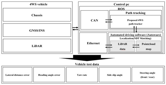
Figure 10.
Architecture of real-car experiment.
Table 3.
Specifications of 4WS platform.
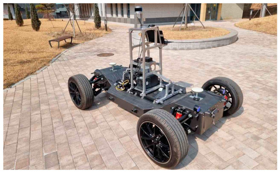
Figure 11.
4WS platform for real-car experiment.
The driving experiment was conducted at two speeds, 5 KPH and 10 KPH, on the Kongju National University campus road in Korea, which has a speed limit of 10 KPH and is primarily paved with asphalt, as shown in Figure 12. This figure presents a PCD (point cloud data) map image and satellite photo of the campus road, depicting the experimental environment. These speeds were chosen to comply with the low-speed autonomous driving criteria defined in the ISO 22737 standard and to satisfy the assumptions of the kinematic model within the permissible speed range of the campus road. Additionally, conducting experiments at 5 KPH and 10 KPH is appropriate for verifying the performance of the proposed controller, as these speeds fall within the target range of low-speed autonomous driving, which is the primary focus of this study.
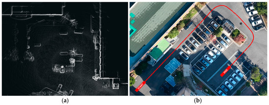
Figure 12.
Real-car experiment environment: (a) PCD map; (b) path on satellite photo.
4.2.2. Real-Car Experiment Results
The real-car experiment results compared the performance of each path tracker at different vehicle velocities. The comprehensive results, which were compared using the RMS, MAX, and SD of the absolute result values, are shown in Table 4, and the graphs for each performance metric are shown in Figure 13.
Table 4.
Real-car experiment results.
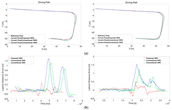
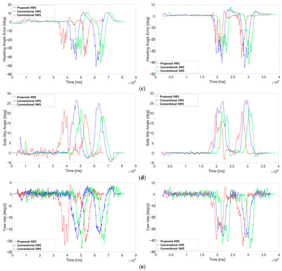
Figure 13.
Real-car experiment results. The left figures show a driving speed of 5 KPH, while the right figures show a driving speed of 10 KPH: (a) driving path; (b) lateral distance error; (c) heading angle error; (d) side-slip angle; (e) yaw rate.
Based on the RMS results of the lateral deviation and heading angle error, it was confirmed that the proposed 4WS path tracker outperformed the other path trackers in terms of tracking performance. This indicates that the autonomous vehicle is likely to demonstrate superior performance in confined spaces.
Regarding the RMS of the side-slip angle, it performed better than the other path trackers at 10 KPH. However, at 5 KPH, it decreased compared to the conventional 2WS path tracker and increased compared to the conventional 4WS path tracker. This is believed to be due to oscillations in the front steering angle caused by issues with control gain optimization in the straight section.
The RMS of the yaw rate increased at 5 KPH compared to the other path trackers. At 10 KPH, it increased compared to the conventional 2WS path tracker but decreased compared to the conventional 4WS path tracker. This is attributed to the use of counter-phase steering, which results in a higher rotational angular velocity than a vehicle using conventional 2WS. However, since the path tracker is designed for low-speed environments, the yaw rate is not expected to affect vehicle stability significantly. Additionally, similar to the RMS, the MAX and SD also tend to decrease in most cases compared to other path trackers. This demonstrates the higher consistency of the proposed path tracker’s performance.
5. Discussion
In this paper, we propose a path tracker for a low-speed automated driving system based on 4WS and verify its performance through simulations and experiments. The path tracker was designed using geometric relationships suitable for low-speed driving with low computational requirements and based on the Stanley method. By incorporating feedforward terms of the curvature of the reference path and the turning radius of the vehicle into the control input, the response characteristics were improved. The lateral distance error and heading angle error, which are performance indicators of the path tracker, were reduced by more than 30% compared to conventional 2WS and conventional 4WS path trackers. Additionally, the reduction in the side-slip angle demonstrated an improvement in vehicle stability. However, in the 5 KPH experiment, it was observed that the side slip angle and yaw rate increased in the existing conventional 4WS path tracker, which is presumed to be due to excessive gain values.
In the future, it is considered necessary to study a lookup table-based gain setting that adjusts the path tracker gain values according to driving speed, as well as adaptive control techniques, and a dynamic model-based path tracker suitable for high-speed driving.
Author Contributions
Conceptualization, H.-S.P. and M.-S.K.; methodology, H.-S.P.; software, H.-S.P.; validation, H.-S.P. and M.-S.K.; formal analysis, H.-S.P.; investigation, H.-S.P.; resources, H.-S.P.; data curation, M.-S.K.; writing—original draft preparation, H.-S.P.; writing—review and editing, M.-S.K.; visualization, H.-S.P.; supervision, M.-S.K.; project administration, M.-S.K.; funding acquisition, M.-S.K. All authors have read and agreed to the published version of the manuscript.
Funding
This work was supported by the Korea Planning & Evaluation Technology (KEIT) grant funded by the Ministry of Trade Industry & Energy (MOTIE, Republic of Korea). (No. 20018448, Development of Demand-responsive Automated Valet Parking and Service Technology).
Institutional Review Board Statement
Not applicable.
Informed Consent Statement
Not applicable.
Data Availability Statement
The original contributions presented in the study are included in the article; further inquiries can be directed to the corresponding authors.
Conflicts of Interest
The authors declare no conflicts of interest.
References
- Wang, R.; Hu, C.; Yan, F.; Chadli, M. Composite nonlinear feedback control for path following of four-wheel independently actuated autonomous ground vehicles. IEEE Trans. Intell. Transp. Syst. 2016, 17, 2063–2074. [Google Scholar] [CrossRef]
- Ni, J.; Hu, J.; Xiang, C. Envelope control for four-wheel independently actuated autonomous ground vehicle through AFS/DYC integrated control. IEEE Trans. Veh. Technol. 2017, 66, 9712–9726. [Google Scholar] [CrossRef]
- ISO 22737:2021; Intelligent Transport Systems—Low-Speed Automated Driving (LSAD) Systems for Predefined Routes. International Organization for Standardization: Geneva, Switzerland, 2021.
- Kim, M.O.; Lee, J.H.; Yoo, W.S. A Study on Optimum Velocity of a Four-Wheel Steering Autonomous Robot. Trans. Korean Soc. Automot. Eng. 2009, 17, 86–92. [Google Scholar]
- Kwon, S.H.; Kang, S.M.; Ahn, H.S. Strategy of Calculating the Steering Angles of Four-wheel-steering Vehicle Model Using Model Predictive Control. ICROS 2016. pp. 151–152. Available online: https://www.dbpia.co.kr/journal/articleDetail?nodeId=NODE06649506 (accessed on 13 January 2025).
- Hang, P.; Chen, X. Towards Autonomous Driving: Review and Perspectives on Configuration and Control of Four-Wheel Independent Drive/Steering Electric Vehicles. Actuators 2021, 10, 184. [Google Scholar] [CrossRef]
- Lin, C.; Li, B.; Siampis, E.; Longo, S.; Velenis, E. Predictive Path-Tracking Control of an Autonomous Electric Vehicle with Various Multi-Actuation Topologies. Sensors 2024, 24, 1566. [Google Scholar] [CrossRef] [PubMed]
- Sun, Y.; Ning, H.; Wang, H.; Wang, C.; Zheng, J. Trajectory Tracking Control Design for 4WS Vehicle Based on Particle Swarm Optimization and Phase Plane Analysis. Appl. Sci. 2024, 14, 3664. [Google Scholar] [CrossRef]
- Moon, C.W.; Kim, J.K. Future of Chassis Technology: E-Corner Module. J. Korea Soc. Mech. Eng. 2022, 62, 32–36. [Google Scholar]
- Tan, X.; Liu, D.; Xiong, H. Optimal Control Method of Path Tracking for Four-Wheel Steering Vehicles. Actuators 2022, 11, 61. [Google Scholar] [CrossRef]
- Snider, J.M. Automatic Steering Methods for Autonomous Automobile Path Tracking; Robotics Institute, Carnegie Mellon University: Pittsburgh, PA, USA, 2009. [Google Scholar]
- Chindamo, D.; Lenzo, B.; Gadola, M. On the Vehicle Sideslip Angle Estimation: A Literature Review of Methods, Models, and Innovations. Appl. Sci. 2018, 8, 355. [Google Scholar] [CrossRef]
- Min, H.; Wu, X.; Cheng, C.; Zhao, X. Kinematic and Dynamic Vehicle Model-Assisted Global Positioning Method for Autonomous Vehicles with Low-Cost GPS/Camera/In-Vehicle Sensors. Sensors 2019, 19, 5430. [Google Scholar] [CrossRef] [PubMed]
- Falcone, P.; Borrelli, F.; Asgari, J.; Tseng, H.E.; Hrovat, D. Predictive active steering control for autonomous vehicle systems. IEEE Trans. Control. Syst. Technol. 2007, 15, 566–580. [Google Scholar] [CrossRef]
- Ackermann, J.; Guldner, J.; Sienel, W.; Steinhauser, R.; Utkin, V.I. Linear and nonlinear controller design for robust automatic steering. IEEE Trans. Control. Syst. Technol. 1995, 3, 132–143. [Google Scholar] [CrossRef]
- Zhou, Q.; Wang, F.; Li, L. Robust sliding mode control of 4WS vehicles for automatic path tracking. In Proceedings of the IEEE Intelligent Vehicles Symposium, Las Vegas, Nevada, USA, 6–8 June 2005; pp. 819–826. [Google Scholar] [CrossRef]
- Tourajizadeh, H.; Sarvari, M.; Ordoo, S. Modeling and Optimal Control of 4 Wheel Steering Vehicle Using LQR and its Comparison with 2 Wheel Steering Vehicle. In Proceedings of the 6th RSI International Conference on Robotics and Mechatronics (IcRoM), Tehran, Iran, 23–25 October 2018; pp. 106–113. [Google Scholar] [CrossRef]
- Spentzas, K.N.; Alkhazali, I.; Demic, M. Kinematics of four-wheel-steering vehicles. Forsch. Im Ingenieurwesen 2021, 66, 211–216. [Google Scholar] [CrossRef]
- Rajamani, R. Vehicle Dynamics and Control; Springer Science & Business Media: New York, NY, USA, 2011. [Google Scholar] [CrossRef]
- Yoo, S.B.; Baek, H.Y.; Choi, K.S. Improvement of Steering Stability by RWS (Rear Wheel Steering) System. In Proceedings of the KSAE Annual Conference, Jeju, Republic of Korea, 18–20 May 2017; pp. 485–490. [Google Scholar]
- Zhang, C.; Gao, G.; Zhao, C.; Li, L.; Li, C.; Chen, X. Research on 4WS agricultural machine path tracking algorithm based on fuzzy control pure tracking model. Machines 2022, 10, 597. [Google Scholar] [CrossRef]
- Dominguez, S.; Ali, A.; Garcia, G.; Martinet, P. Comparison of lateral controllers for autonomous vehicle: Experimental results. In Proceedings of the IEEE 19th International Conference on Intelligent Transportation Systems (ITSC), Rio de Janeiro, Brazil, 1–4 November 2016; pp. 1418–1423. [Google Scholar] [CrossRef]
- Lombard, A.; Buisson, J.; Abbas-Turki, A.; Galland, S.; Koukam, A. Curvature-based geometric approach for the lateral control of autonomous cars. J. Frankl. Inst. 2021, 357, 9378–9398. [Google Scholar] [CrossRef]
- Campbell, S.F. Steering Control of an Autonomous Ground Vehicle with Application to the DARPA Urban Challenge. Ph.D. Thesis, Massachusetts Institute of Technology, Cambridge, MA, USA, 2007. [Google Scholar]
- Sun, C.; Zhang, X.; Xi, L.; Tian, Y. Design of a Path-Tracking Steering Controller for Autonomous Vehicles. Energies 2018, 11, 1451. [Google Scholar] [CrossRef]
- Gámez Serna, C.; Ruichek, Y. Dynamic Speed Adaptation for Path Tracking Based on Curvature Information and Speed Limits. Sensors 2017, 17, 1383. [Google Scholar] [CrossRef] [PubMed]
- Xu, S.; Peng, H. Design, analysis, and experiments of preview path tracking control for autonomous vehicles. IEEE Trans. Intell. Transp. Syst. 2019, 21, 48–58. [Google Scholar] [CrossRef]
- Lee, S.J. Methodology of an Adaptive Look-Ahead Distance to Improve Autonomous Driving Path-Tracking Performance. Master’s Thesis, Kookmin University, Seoul, Republic of Korea, 2023. [Google Scholar] [CrossRef]
- Samuel, M.; Hussein, M.; Mohamad, M.B. A review of some pure-pursuit based path tracking techniques for control of autonomous vehicle. Int. J. Comput. Appl. 2016, 135, 35–38. [Google Scholar] [CrossRef]
- Mercedes-Benz USA. Available online: https://media.mbusa.com/releases/release-7122b266eca9fbce132ea26634041549-2022-mercedes-benz-s-class-sedan-quick-reference-guide (accessed on 5 August 2021).
- Kim, S.Y. Point Cloud Map Generation and Localization Algorithm Based on Deep Learning and NDT for Autonomous Vehicles. Master’s Thesis, Kookmin University, Seoul, Republic of Korea, 2021. [Google Scholar]
- Biber, P.; Strasser, W. The normal distributions transform: A new approach to laser scan matching. Proc. IEEE 2013, 3, 27–31. [Google Scholar]
Disclaimer/Publisher’s Note: The statements, opinions and data contained in all publications are solely those of the individual author(s) and contributor(s) and not of MDPI and/or the editor(s). MDPI and/or the editor(s) disclaim responsibility for any injury to people or property resulting from any ideas, methods, instructions or products referred to in the content. |
© 2025 by the authors. Licensee MDPI, Basel, Switzerland. This article is an open access article distributed under the terms and conditions of the Creative Commons Attribution (CC BY) license (https://creativecommons.org/licenses/by/4.0/).