Next Article in Journal
Automatic Identification and Segmentation of Overlapping Fog Droplets Using XGBoost and Image Segmentation
Previous Article in Journal
Establishing Two-Dimensional Dependencies for Multi-Label Image Classification
 
 
Correction published on 10 April 2025, see Appl. Sci. 2025, 15(8), 4158.
Article

Underwater Ionic Current Signal Sensing and Information Transmission by Contact-Induced Charge Transfer

by
Boru Su
1,
Junyan Zhang
2,*,
Yunfei Deng
2 and
Lin Chi
3
1
Information Science and Technology College, Dalian Maritime University, Dalian 116026, China
2
Marine Engineering College, Dalian Maritime University, Dalian 116026, China
3
Inner Mongolia Company, State Power Investment Corporation Ltd., Tongliao 028000, China
*
Author to whom correspondence should be addressed.
Appl. Sci. 2025, 15(5), 2846; https://doi.org/10.3390/app15052846
Submission received: 5 February 2025 / Revised: 28 February 2025 / Accepted: 2 March 2025 / Published: 6 March 2025 / Corrected: 10 April 2025
(This article belongs to the Section Surface Sciences and Technology)

Abstract

:
Underwater ionic current signal sensing shows great potential for electric-field-sensing-based target detection, information transmission and communication. Nevertheless, it is still a challenging task. Herein, a self-powered underwater ionic current signal sensing system using contact-induced charge transfer is presented. The system mainly consists of a working electrode, a metal sheet and a sensing electrode that is immersed in electrolyte solution. Upon touching the working electrode with a metal sheet with a different work function, charge transfer occurs on the interface, and a corresponding ionic current is induced. The generated ionic current can be detected with the sensing electrode far away from the working electrode. It was found that the magnitude and direction of the generated ionic current are determined by the contact potential difference (CPD) between the working electrode and the contacting metal sheet. Additionally, the effects of water temperature, the ionic concentration of the electrolyte solution, electrode surface area and hydrostatic pressure are systematically investigated. The detected signal magnitude decreased with an increase in the distance between the working electrode and the sensing electrode. A proof-of-concept demonstration of underwater information transmission via Morse code with this method was successfully achieved.

1. Introduction

Underwater electric signal sensing [1,2] shows great potential for electric-field-sensing-based target detection [3], positioning [4], signal transmission [5] and communications [6], among others. Nevertheless, underwater equipment such as underwater manipulators, autonomous underwater vehicles and workstations rely heavily on electric power supply [7,8]. Therefore, it is of great importance to develop self-powered sensing methods for underwater activities. Based on working principles, the electric current or electric voltage signals generated for sensing can be generally derived from three methods: piezoelectric, triboelectric and piezoionic.
The piezoelectric method is based on the piezoelectric effect, where a voltage difference across the piezoelectric material is generated as it is pressed [9]. Thus, the mechanical energy is directly converted into electricity. Piezoelectric materials, such as quartz, PZT, ZnO, PVDF and piezoelectric composites [10,11], are widely used for electricity generation on land. However, these materials must respond to strain caused by various stimuli, and the high hydrostatic pressure in deep-sea environments can easily deform them, limiting their effectiveness in such conditions.
Underwater electric current generated for sensing based on the triboelectric effect have also been proposed. Compared to land-based triboelectric nanogenerators (TENGs), underwater TENGs should be specially designed to adapt to the complexity of the underwater environment [12]. To further optimize the underwater performance of TENGs, diverse designs including origami structure [13], electrode geometry [14], triboelectric layer innovation [15], biomimetic structure (seaweed, jellyfish, sea anemones, etc.) [16,17,18] and electric double layer (EDL)-based structure [19] have been proposed. Nevertheless, as mobile ions in water can neutralize the electrostatic charges of TENGs [20], waterproof structures including shell, encapsulation, and coatings are necessary to avoid this side effect [21].
Distinct from the piezoelectric effect or triboelectric effect, using electrons as charge carriers, electric currents can also be generated through the piezoionic effect. Ionic transportation is utilized to produce an electrical output when pressure is applied [22]. Several underwater applications, such as piezoionic elastomers and TPU film-based tactile sensors, have been developed using the second type of piezoionic process [23,24]. Nevertheless, the piezoionic materials have to withstand long-term soaking in an aquatic environment [25]. Moreover, the mechanical strength is insufficient to work under high hydrostatic pressure conditions, such as in the deep sea [26].
While the methods of electric current signal-based sensing show some potential in underwater applications, the shortcomings are obvious. Contact electrification (CE) provides a possible solution. The CE of contact and separation mode refers to the charge transfer between the two different materials [27,28], where net positive charges accumulate on one material and net negative charges on the other [29]. For a metal/metal contact pair, electrons are transferred between the two metal surfaces, resulting in a contact potential difference (CPD) between the two contacted metals. From the pioneering investigations of the electron transfer mechanism between metal and metal by Harper [30] and Lowell [31], it was revealed that the work function is the minimum work needed to extract the electrons from the Fermi level of a solid carrying a net charge [32,33]. Therefore, electrons will flow from the metal with a smaller work function to the metal with a larger work function until the equilibrium of the Fermi level is achieved [34].
Based on the above-mentioned mechanism, the electric potential difference of the electrodes can be determined via the modulation of the electrode distance by through applying the scanning Kelvin probe (SKP) method [35]. The suitability of a material is likely correlated with its work function, resulting from the conclusion of the higher work function and the higher resolution of the electrochemical potential [36]. With the help of this non-destructive method, the work function of a metal is mapped to evaluate the relationship between the metal surface defects and the electrochemical potential [37]. Kaponig et al. [38], employing a small gold sphere bouncing on a planar metal electrode, examined the CE of metals and focused on the charging and discharging process when the metal touched and detached, respectively. The charge transfer was found to be limited to the short contact and no charge was accumulated in the following contacts.
It can be seen that the majority of the investigations have been conducted in air or under vacuum. However, the process of the charge transfer between two contacting metals also occurs in underwater conditions. To the best of our knowledge, the only research on metal/metal contact in electrolyte to date is a numerical study of the potential distribution around bimetallic Janus nanoparticles, indicating that the electric field induced by the CE is disrupted beyond the Debye length [39]. Nevertheless, the fundamental mechanism that underlies the charge (electron) transfer and electricity generation via the CE of metal/metal sheets in underwater conditions is still not completely understood.
In this study, we propose a novel method using bi-metal CE to generate underwater ionic current signals for self-powered sensing. Focus is given to the charge transfer process during the contact and separation between the two metal sheets in water, where one metal is the working electrode, and the ionic current signals are detected far away by the sensing electrode. The effects of metal type, water temperature, ionic concentration and electrode distance on the sensing capability of the ionic current signals were investigated systematically. As a typical application, underwater information transmission via Morse code was demonstrated using the proposed method.

2. Mechanism of Ionic Current Sensing

The system mainly consists of a copper working electrode (for contacting a metal object) and an electrometer connected in series with a copper sensing electrode. Both the working electrode and the sensing electrode, as well as the metal sheet, are immersed in an electrolyte solution. The mechanism of the contact-induced ionic current sensing can be understood as follows. Initially, the working electrode, sensing electrode and the metal sheet are immersed in the electrolyte solution without contact. Generally, a metal electrode is negatively charged in an electrolyte solution. As a result, the cations are attracted onto the electrode surface to form a so-called EDL. Since the materials of the two electrodes are the same, there is a neglected potential difference between them. As a result, there will be no electron flow between them before the working electrode and the metal sheet come into contact.
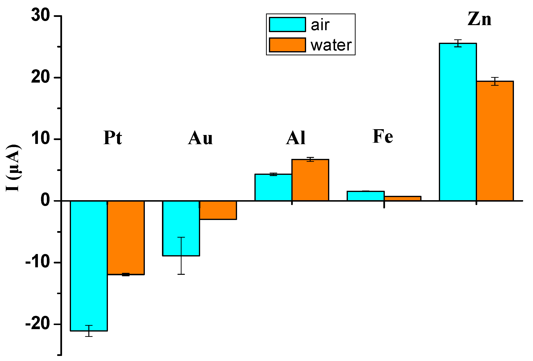
When the copper working electrode and the metal sheet with a higher work function (e.g., gold sheet) are brought into electrical contact (Figure 1), some electrons will be transferred from the copper working electrode to the gold sheet until their Fermi levels are equal [33]. This process of electron migration leads to the generation of a contact potential difference (CPD) at the interface of the copper working electrode and the gold sheet. Specifically, the electric potential of the gold sheet is higher than that of the copper working electrode. As electrons move from the copper working electrode to the gold sheet, some electrons will migrate accordingly from the ground to the copper working electrode. For the gold sheet after contact, it becomes the new working electrode (named the gold-composite working electrode) with the copper working electrode working as the function of a copper electric wire. Meanwhile, the electric potential of the sensing electrode is unchanged. Then, the potential difference between the gold-composite working electrode and the sensing electrode is increased to an electric potential difference ΔV. Accordingly, the cations and the anions in the electrolyte solution are attracted to the gold-composite working electrode/electrolyte solution interface and the sensing electrode/electrolyte solution interface, respectively, forming the EDL capacitors. The accumulated anions on the sensing electrode/electrolyte solution interface will be neutralized by the discharged electrons through the electrometer. According to the connection of the electrometer discussed above, a negative ionic current signal pulse is detected.
Similarly, when the copper working electrode contacts a metal sheet with a lower work function (e.g., aluminum sheet), the aluminum sheet works as a function of the new working electrode (named the aluminum-composite working electrode). The electrons will flow from the aluminum-composite working electrode to the copper working electrode, leading to a lower electric potential of the aluminum-composite working electrode. Then, the anions and the cations are attracted onto the surfaces of the aluminum-composite working electrode and the sensing electrode, respectively. The accumulated cations on the sensing electrode/electrolyte solution interface will attract the electrons to the sensing electrode through the electrometer. Therefore, a positive ionic current signal pulse will be detected.
It should be noted that the above-mentioned contact-induced ionic current is a non-Faradaic current, where only ion absorption and detachment at the electrode/electrolyte solution interface are involved. The contact-induced ionic current sensing process can be electrically modeled with an equivalent circuit. Specifically, the composite working electrode and the sensing electrode can be modeled as the parallel of a resistor R (R1, R2) and an EDL capacitor C (C1, C2), respectively. There is also a water resistor Rs between the two electrodes. In the equivalent circuit, the sum of the voltages, VR and Vc, across the water electric resistor and the EDL capacitors, respectively, should be equal to ΔV [40].
ΔV = VR + Vc = I Rs + QS/C
where QS is the mobile charges induced in the electric circuit. The ionic current can be expressed as I = d QS/dt. Therefore, Equation (1) is rearranged as
d QS/dt = −QS/(RsC) + ΔV/Rs
If we integrate Equation (2), then
QS = ΔVC[1 − e−t/RsC]
The ionic current I can be expressed by combining Equations (2) and (3).
I = d QS/dt = V/Rs e−t/RsC
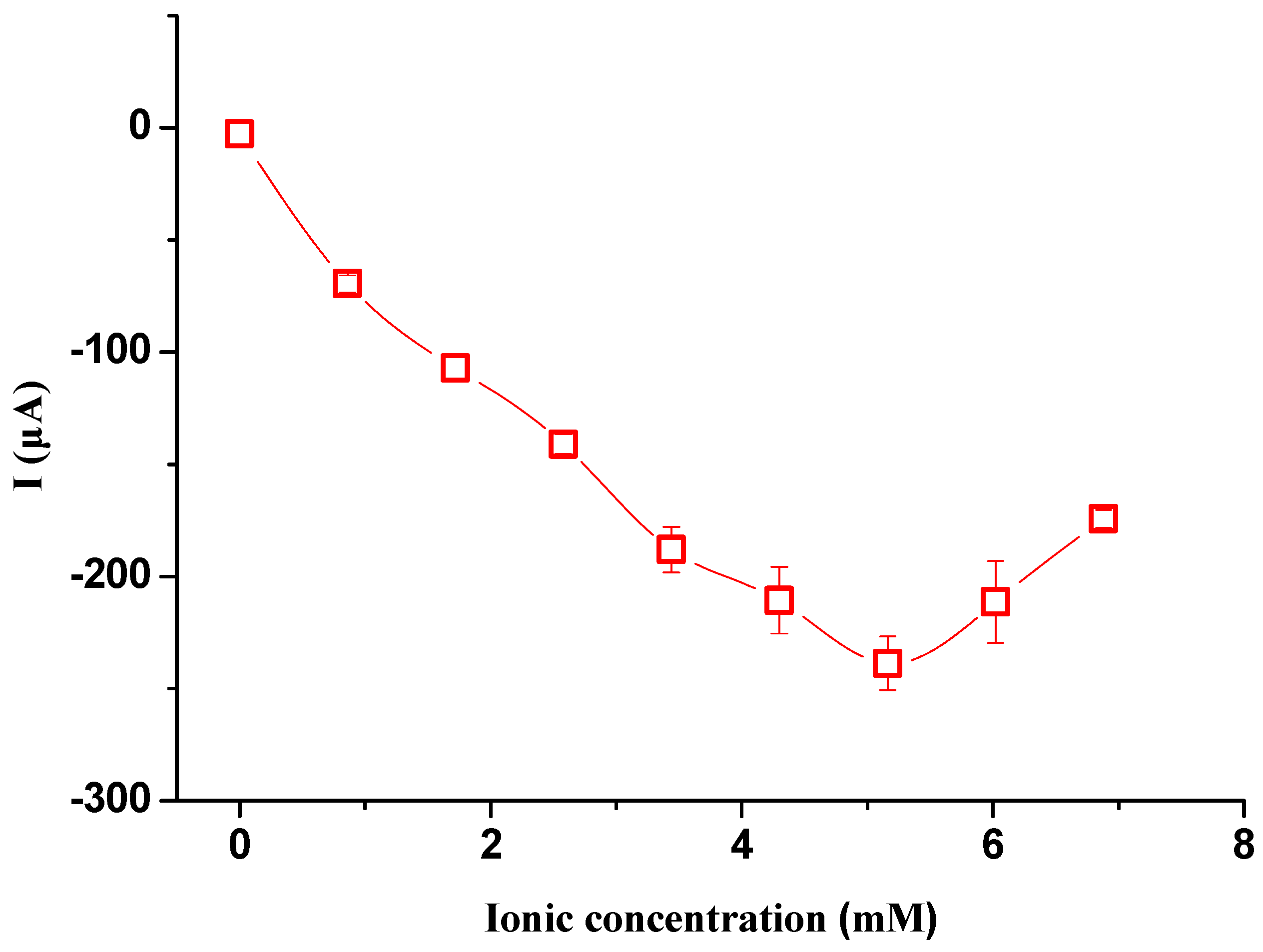
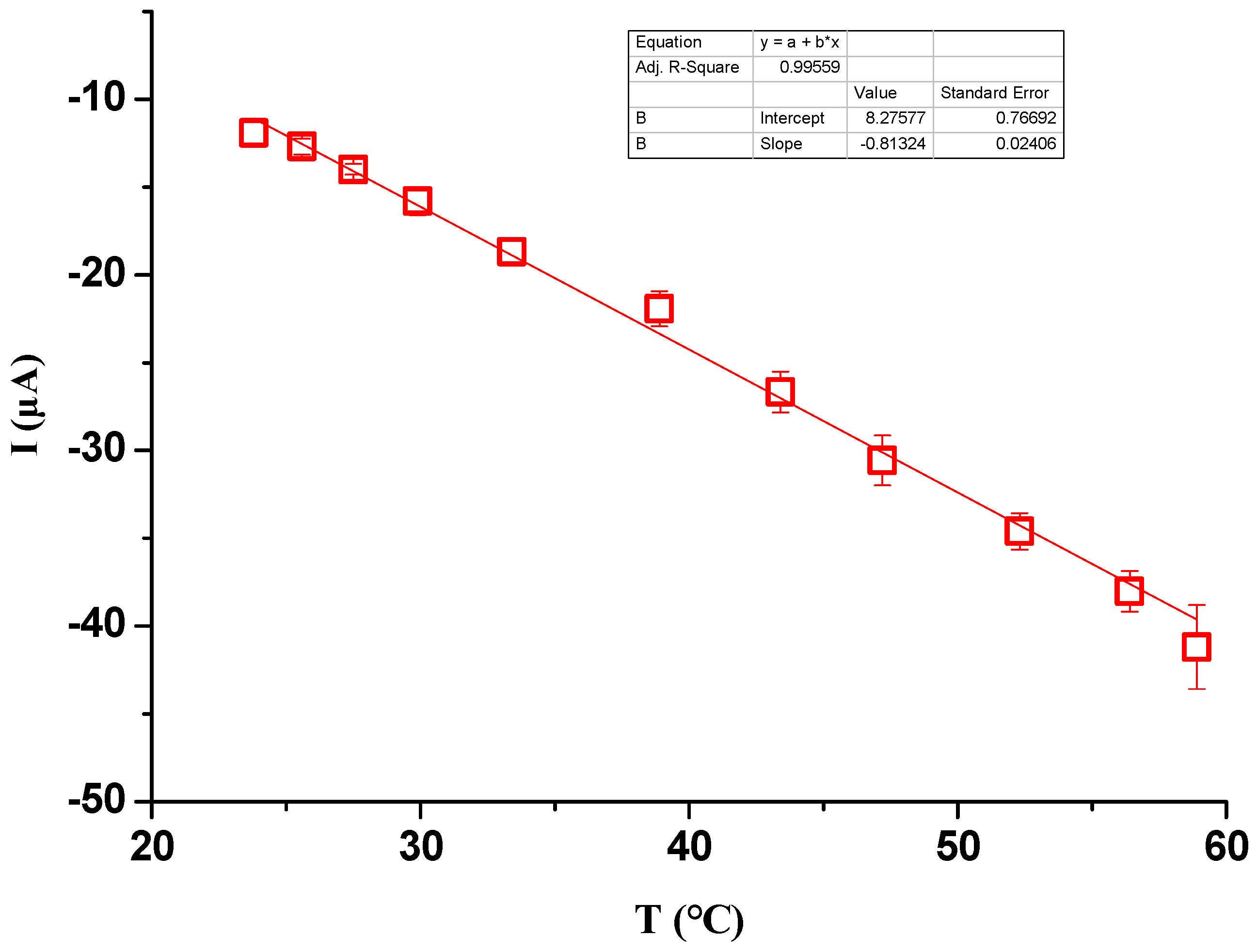
From Equation (4), we can see that the ionic current decays with a time constant τ (τ = RsC) and the ionic current reaches a peak value (Imax = ΔV/Rs) at the moment when CPD is generated. As we only focus on the signal pulse of the ionic current, except where indicated, all the ionic current signals discussed in this study are the peak values of the ionic current. It can be seen that the magnitude of the ionic current increases with the increase in ΔV and decreases with the increase in the electric resistor of water Rs. As Rs decreases with the increase in the ionic concentration of the electrolyte solution in a certain concentration range and increases with the increase in electrode distance, it can be predicted that the ionic current signals increase with the increase in ionic concentration and decrease with the increase in electrode distance.

3. Experimental Setup

3.1. Materials

In the experimental system, a water tank was primed with deionized (DI) water (18.2 ΜΩ) or NaCl solution. DI water was produced using a laboratory water purification system (Smart series, HETAI, Shanghai, China), and the NaCl solution was prepared by diluting a certain amount of NaCl (99.5% purity, Tianjin Zhiyuan, Tianjin, China) in DI water. The copper working electrode and the sensing electrode are both cylindrical with a diameter of 1 mm. The sensing electrode is connected in series with an electrometer (6517B, Keithley, Cleveland, OH, USA). A homemade NI LabVIEW 2018 program was used to record the real-time ionic current signals measured with the electrometer. Gold (Au), platinum (Pt), copper (Cu), aluminum (Al), iron (Fe) and zinc (Zn) were used as the metal sheets (10 mm × 15 mm × 1 mm) in the experiments. None of the metal sheets were further treated regarding the oxidation layers.

3.2. Procedures

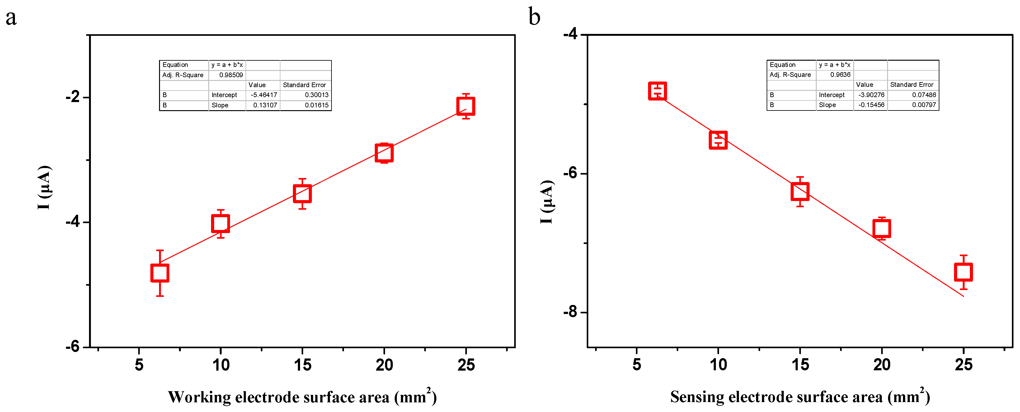
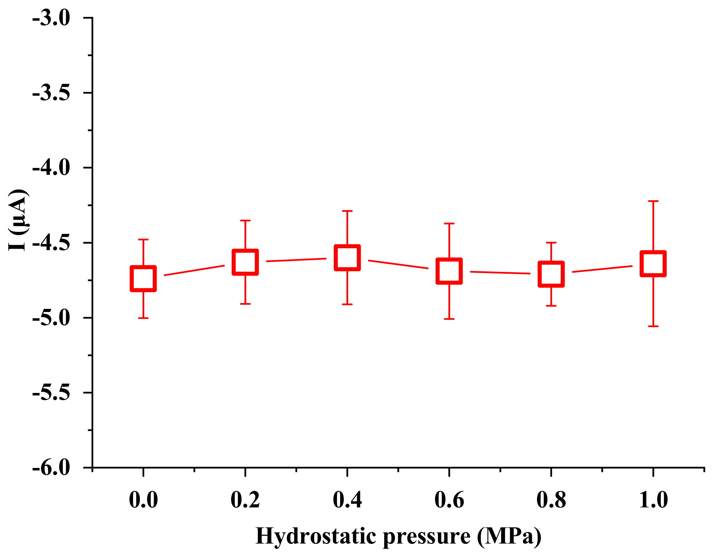
In this study, the effects of ionic concentration, water temperature, electrode surface area, electrode distance and hydrostatic pressure on the ionic current signals were investigated. To start the experiment, the working electrode, the sensing electrode and the metal sheet were immersed in the liquid. Then, the working electrode was manually moved to contact the metal sheet and detached from the metal sheet after the peak value was reached. The above processes were repeated three times, and the ionic current signals were obtained by averaging the three measurements. Ionic concentration ranging from DI water to 7.0 mM NaCl solution was investigated. To check the effect of water temperature on the generated signals, a digital hot plate was used to heat the liquid to a certain temperature. To check the effect of the electrode distance on the generated signals, the working electrode and the metal sheet were inserted into one end of a 60 m long water pool, while the sensing electrode was inserted into the opposite end. Other experiments were conducted under room temperature conditions (23 ± 1 °C).

4. Results and Discussion

4.1. Typical Ionic Current Signals

Figure 2 shows the measured ionic current signals during the process of contacting different metal sheets with the working electrode in DI water (experimental data can be seen in Table A1 of Appendix A). It can be seen that the ionic current signals are different for different metals, in both direction and magnitude. In detail, the ionic current signals generated by the gold, platinum and copper sheets are in a downwards direction, while those of the aluminum, iron and zinc sheets are in an upwards direction. The magnitudes of the ionic current signals generated are also different for the different metal sheets. Among the six tested metal sheets, the values of the ionic current increase in the sequence of platinum, copper, gold, iron, aluminum and zinc. For example, the ionic current generated by the gold sheet is about −2.5 μA, while that generated by the aluminum sheet is about 6.9 μA.
As discussed in Section 2, this is mainly attributed to the different CPDs that generate the different potential difference between the composite working electrode and the sensing electrode. Meanwhile, the CPD depends on the difference in the work functions of the two contacted metals. As the work function of the copper ( ϕ C u , 4.53–5.1 eV) working electrode is lower than that of the gold one ( ϕ A u , 5.1–5.47 eV), the CPD generated by contacting the gold sheet leads to a higher electric potential on the gold-composite working electrode compared with the copper sensing electrode, which is responsible for the negative ionic current. Similarly, as the work function of the copper ( ϕ C u , 4.53–5.1 eV) working electrode is higher than that of the aluminum sheet ( ϕ a l , 4.06–4.26 eV), the CPD generated by contacting the aluminum sheet leads to a lower electric potential on the aluminum-composite working electrode compared with the copper sensing electrode, which is responsible for the positive ionic current. Other ionic current signals can also be understood in the same way regarding the work functions of other metals [29]—Pt (5.12–5.93 eV), Fe (4.67–4.81 eV), Al (4.06–4.26 eV) and Zn (3.63–4.33 eV).
To confirm that the ionic current is generated between the composite working electrode and the sensing electrode, different immersing media (air or DI water) where the copper working electrode is in contact with the metal sheet are compared. Unlike the experimental system described in Section 2, for the contact position in air, the metal sheet is placed vertically across the air/water interface, where part of the metal sheet is in water and the other part is in air. Then, the metal sheet is contacted with the copper working electrode in air. Figure 3 shows a comparison of the ionic current generated by contacting the metal sheet in air or in DI water (experimental data can be seen in Table A2 of Appendix A). It can be seen that for all the contacted metal sheets, the direction of the generated ionic current signals is the same for both the contact positions in air or DI water, meaning that the electron transfer between the copper working electrode and the metal sheet occurs in air. Then, the ion migration and the ionic current are generated between the composite working electrode and the sensing electrode. Supposing the ionic current is still generated by the copper working electrode and the sensing electrode after contact, as the copper working electrode and the composite working electrode are oppositely charged after the copper working electrode and the metal sheet come into contact, the direction of the ionic current for the contact position in air should be opposite to that for the contact position in DI water. It is thus verified that after the working electrode and the metal sheet come into contact, the ionic current is generated between the composite working electrode and the sensing electrode.

4.2. Effect of Ionic Concentration

Since the generated ionic current is induced by the ionic migration of anions and cations, the properties of the electrolyte solution, such as ionic concentration, should influence the generated ionic current. Therefore, the effect of ionic concentration on the ionic current signal is examined by contacting the gold sheet with the copper working electrode (Figure 4; experimental data can be seen in Table A3 of Appendix A). It was found that, from DI water (containing no NaCl) to 5.1 mM NaCl solution, the magnitude of the ionic current signals increases with the ionic concentration and reaches a peak value when the ionic concentration is about 5.1 mM, which is about 250 times higher than that in DI water. It is known that a higher ionic concentration of NaCl solution means more Na+ and Cl ions in the electrolyte solution, as well as on the contacted metal or the electrode/electrolyte solution interfaces. Therefore, the equivalent resistance of the water phase (Rs) decreases with the increase in the ionic concentration of the electrolyte solution. According to Equation (4), the ionic current signal increases with decreasing Rs, hence the increase in ionic concentration.
However, when the ionic concentration was further increased from 5.1 mM to 7.0 mM, the magnitude of the ionic current signal started to decrease. It is reported that with the increase in ionic concentration, the increasing ionic conductivity has a peak value from 3.5 mM to 4.5 mM [41], while in our experiment, the peak value of the ionic current was 5.1 mM. It is possible that the amount of mobile Na+ and Cl ions attracted onto the interface of the two metals reaches a saturation point [42]. As the ionic concentration further increases higher than this saturation value, the interaction (such as mutual collision) between the ions at a high concentration is greatly enhanced, which hinders the ion migration, as well as the conduction of ions [43].

4.3. Effect of Water Temperature

To examine the effect of water temperature on the ionic current signals, experiments with the water temperature ranging from 23 °C to 60 °C were conducted. It was found that the peak values of the ionic current pulses are water temperature dependent. As shown in Figure 5 (experimental data can be seen in Table A4 of Appendix A), the magnitude of the ionic current signals generated by contacting the platinum sheet with the copper working electrode in DI water are linearly proportional to the water temperature from about 23 °C to 60 °C. Nevertheless, this experiment was conducted in DI water, and there are few mobile ions in DI water. The effect of water temperature on the ionic current has a limited relationship with ion migration. Such a result can be attributed to CPD generation. It is well known that the work function represents the minimum thermodynamic work needed to remove an electron from a solid to a point in the vacuum. Although the work function itself does not change with temperature, the electrons inside the material will gain more energy due to the increasing temperature. This can cause the energy of some electrons to exceed the energy threshold of the work function, thereby increasing the probability of more electrons transferring from the copper working electrode to the gold sheet. As a result, a larger electric current pulse will be detected with higher water temperature.

4.4. Effect of the Distance Between the Electrodes

As the detected ionic current is induced by ion migration, there should be an attenuation of the signals with the increase in the distance between the two electrodes. The effect of the distance (within 60 m) between the working electrode and the sensing electrode on the ionic current signals was investigated in the water pool with tap water. It can be seen from Figure 6 that the peak values of the ionic current signals decrease with the increase in the distance between the working electrode and the sensing electrode (experimental data can be seen in Table A5 of Appendix A). The magnitude of the signals decreases in almost one order for each electrode distance increase of 10 m. As a result, the detected ionic current signal decreases from 233 μA to 1.5 μA when the electrode distance increases from 0 m to 60 m. The results can be explained with the electric resistance of water, which increases with the increase in the electrode distance. Meanwhile, the EDL capacitor is unchanged. Therefore, a longer electrode distance leads to a smaller ionic current.

4.5. Effect of Electrode Surface Area

As discussed in Section 2, EDL capacitors were formed at the interface of the electrode and water. Therefore, the total induced mobile charges should be dependent on the capacitance of the EDL capacitors. To investigate the dependence, the effect of the electrode surface area on the generated ionic current was studied by bringing the gold sheet into contact with different electrode surface areas. Figure 7a shows the experimental results of the ionic current when the working electrode surface area increases (experimental data can be seen in Table A6 of Appendix A). The results showed that the ionic current decreased linearly in magnitude with the increase in working electrode surface area. As the copper working electrode worked as the function of an electric wire, the larger surface area meant more mobile counter ions were attracted to the surface to neutralize the electrons. This result led to a decreased trend in the ionic current with the increase in working electrode surface area. Nevertheless, the ionic current increased linearly in magnitude with the increase in the sensing electrode surface area. The results are shown in Figure 7b (experimental data can be seen in Table A7 of Appendix A). It is clearly evident that more surface charges were attracted to the surface of the sensing electrode, leading to a larger ionic current.

4.6. Effect of Hydrostatic Pressure

Underwater sensing and information transmission should be capable of working in deep water conditions. To determine the effect of the hydrostatic pressure exerted on the sensing performance of our device, a homemade high-pressure stainless-steel tank was employed to mimic the high hydrostatic pressure environment [23,44]. The ionic current generated by contacting the gold sheet with the copper working electrode was measured and recorded in the high-pressure tank. The gauge pressure was adjusted from 0 MPa to 1 MPa. Figure 8 shows the dependence of the ionic current signals on the hydrostatic pressure (experimental data can be seen in Table A8 of Appendix A). It can be clearly seen that the magnitude of the ionic current signals was kept almost unchanged as the gauge pressure of the tank increased from 0 to 1 MPa. Therefore, the hydrostatic pressure showed little effect on the ionic current signals.

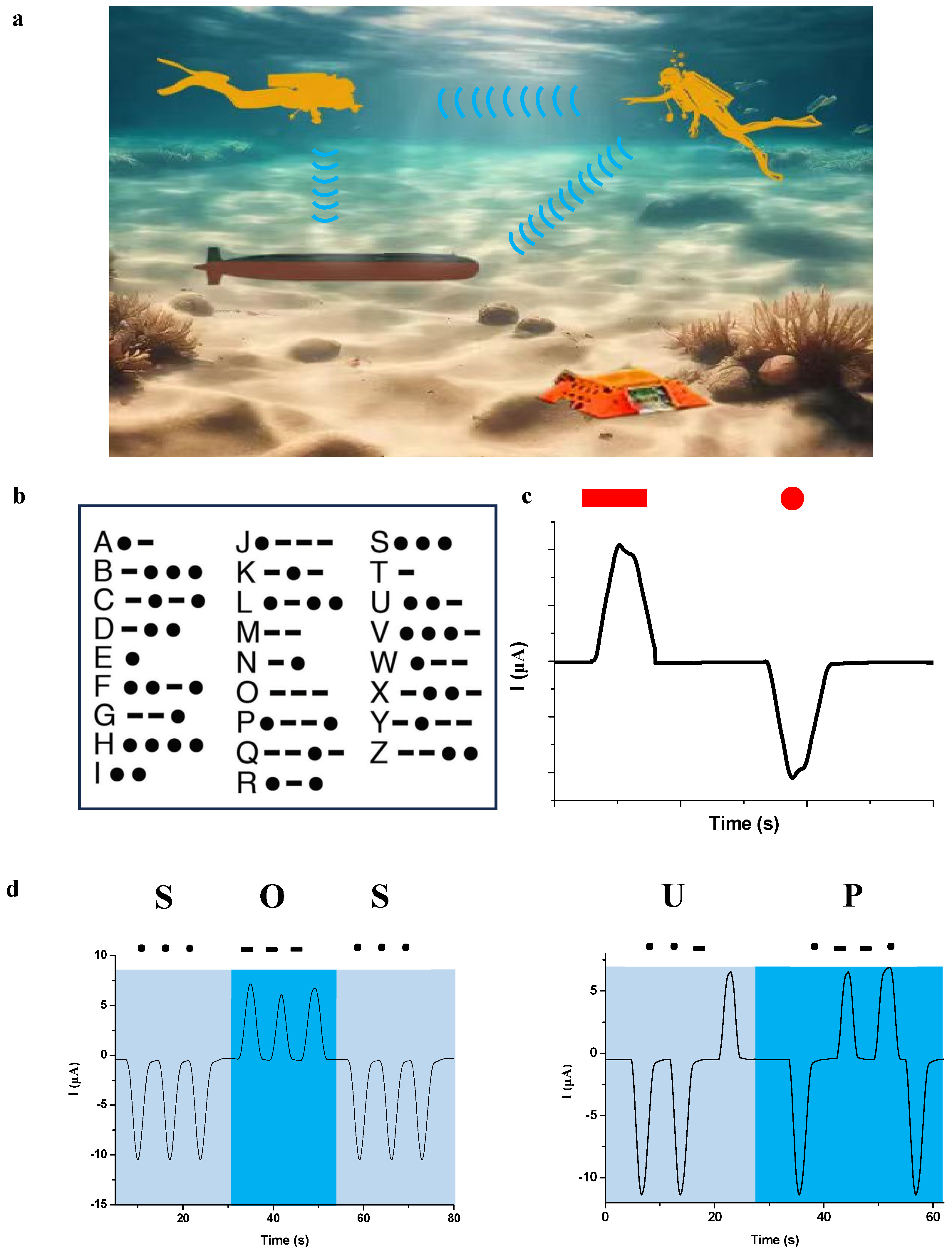
5. Application of Information Transmission

Other than in the civilian field, silent information transmission has received increasing attention in special fields where stealth is a necessity. For example, near-field frogmen need to exchange information with their colleagues, as well as remote-operated vehicles or bases in the sea without being detected (Figure 9a). As is well known, Morse code is an effective way to transmit information, and it has been used for well over a century. Different Latin alphabets are represented by different configurations of “dot” and “dash” symbols (Figure 9b). Based on the contact-induced ionic current-generating system and Morse code, we proposed a wireless self-powered device that can silently transmit information in underwater conditions via a modulating decoder to translate the ionic current signals into intelligible letters. The device comprises a signal modulator, an LCD display, a portable lithium battery, a copper working electrode and a copper sensing electrode. In addition, an aluminum sheet and a platinum sheet are secured onto the surface of the gloves. It is therefore possible to generate the ionic current using only three fingers on one hand.
The working principle of the system is as follows. Firstly, we define the positive ionic current pulse generated by contacting the aluminum sheet as the “dash” and the negative ionic current pulse generated by the platinum sheet as the “dot”, as shown in 
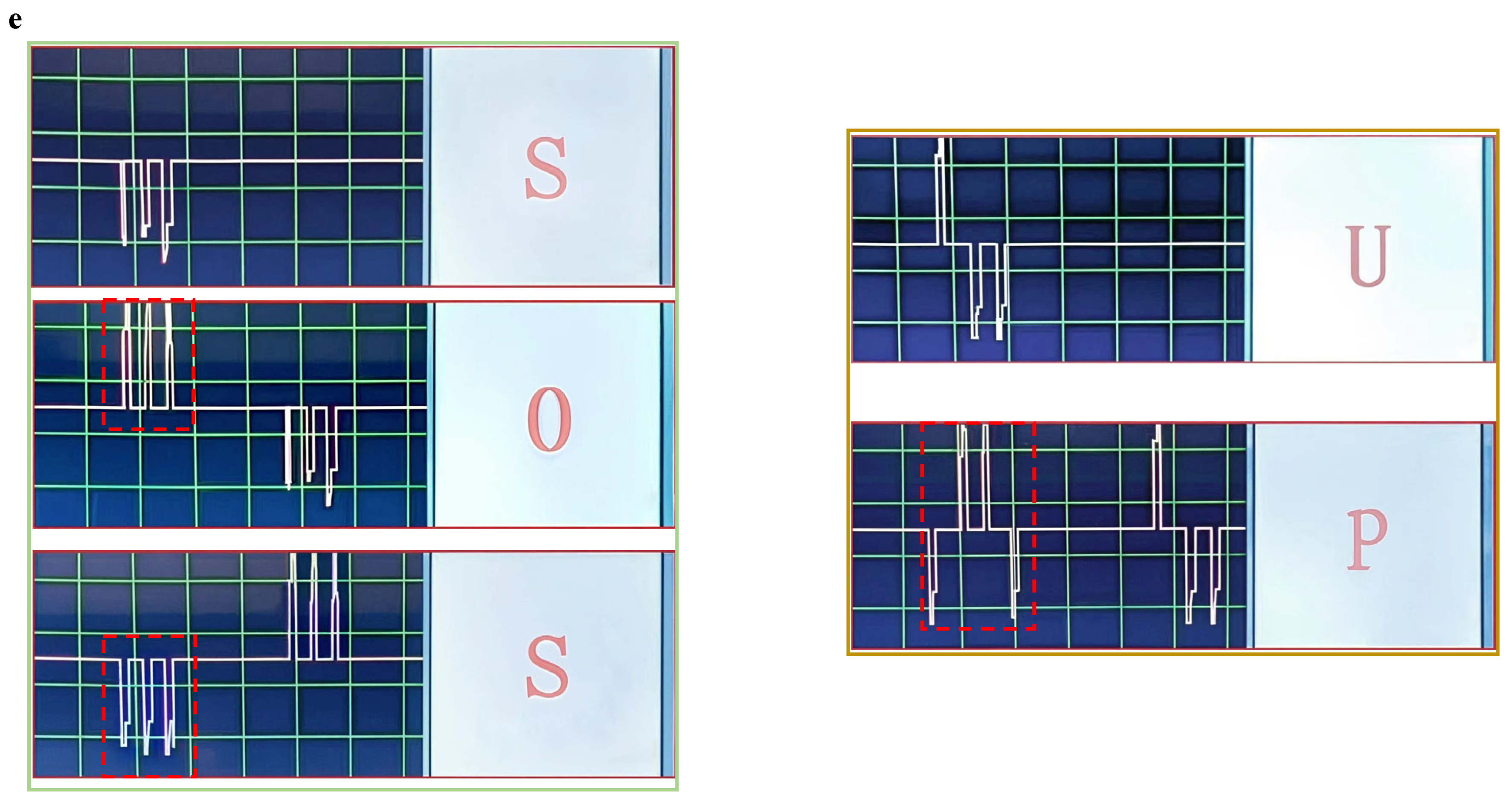
Figure 9c. For example, the letters S and O are generated by consecutively contacting the platinum sheet and the aluminum sheet three times with the copper working electrode, respectively. Then, messages such as “SOS” and “UP” (Figure 9d) are expressed by contacting the aluminum or the platinum sheets representing “dash” or “dot” in appropriate sequence and displayed on the screen of the decoder, respectively (Figure 9e). Other information, such as “GO” and “HELP”, can also be conveyed by simply contacting the two fingers with metal sheets in underwater conditions using the same process. Therefore, silent information transmission can be achieved between vehicles and scuba divers.

6. Conclusions

In summary, an underwater contact-induced ionic current sensing system and a silent underwater information transmission method were proposed in this article. The generated ionic current signals were due to the potential difference between the sensing electrode and the composite working electrode. The magnitude and the direction of the ionic current signals depend on the material of the metal, water temperature, ionic concentration and electrode distance. The method proposed in this article is simple and self-powered, and it is promising in fields where silent underwater information transmission is a necessity.

Author Contributions

Conceptualization, J.Z.; methodology, B.S.; software, L.C.; validation, B.S. and Y.D.; formal analysis, B.S. and Y.D.; data curation, L.C.; writing—original draft preparation, B.S. and J.Z.; writing—review and editing, J.Z. All authors have read and agreed to the published version of the manuscript.

Funding

This work is supported by the Open Fund of the National Center for International Research of Subsea Engineering Technology and Equipment (HG20240102) and the National Natural Science Foundation of China (52001049) to Junyan Zhang.

Institutional Review Board Statement

Not applicable.

Informed Consent Statement

Not applicable.

Data Availability Statement

The original contributions presented in this study are included in the article. Further inquiries can be directed to the corresponding author.

Acknowledgments

We thank the anonymous reviewers for their comments and suggestions, which greatly improved the manuscript.

Conflicts of Interest

Author Lin Chi was employed by the company Inner Mongolia Company, State Power Investment Corporation Ltd. The remaining authors declare that the research was conducted in the absence of any commercial or financial relationships that could be construed as a potential conflict of interest.

Appendix A

Table A1. Experimental data of Figure 2.
Metal MaterialsPulse of Current 1 (μA)Pulse of Current 2 (μA)Pulse of Current 3 (μA)
Pt−11.14−11.33−11.37
Au−2.58−2.57−2.61
Fe0.960.950.91
Al7.386.536.90
Zn19.5819.1518.16
Table A2. Experimental data of Figure 3.
Metal MaterialsCurrent in Air (μA)Current in Water (μA)
Pt −21.01−11.93
Au−8.90−2.65
Al4.336.73
Fe1.570.91
Zn25.5719.40
Table A3. Experimental data of Figure 4.
Ionic Concentration (mM)Ionic Current (μA)
0 −2.70
0.86−69.47
1.72−107.05
2.58−141.10
3.44−188.31
4.3−210.67
5.16−238.67
6.02−211.33
6.88−174.33
Table A4. Experimental data of Figure 5.
Water Temperature (°C)Ionic Current (μA)
23.8−11.93
25.6−12.70
27.5−14.00
30−15.80
33.4−18.70
38.9−21.93
43.4−26.67
47.2−30.57
52.3−34.60
56.4−38.02
58.9−41.20
Table A5. Experimental data of Figure 6.
Distance (m)Ionic Current (μA)
0 232.63
2035.77
405.40
601.31
Table A6. Experimental data of Figure 7a.
Surface Area (mm2)Ionic Current (μA)
6.28 −4.81
10−4.02
15−3.54
20−2.89
25−2.14
Table A7. Experimental data of Figure 7b.
Surface Area (mm2)Ionic Current (μA)
6.28 −4.83
10−5.52
15−6.26
20−6.79
25−7.42
Table A8. Experimental data of Figure 8.
Hydrostatic Pressure (MPa)Ionic Current (μA)
0 −4.74
0.2−4.63
0.4−4.60
0.6−4.69
0.8−4.71
1−4.64

References

  1. Chang, Y.; Wang, L.; Li, R.; Zhang, Z.; Wang, Q.; Yang, J.; Guo, C.F.; Pan, T. First decade of interfacial iontronic sensing: From droplet sensors to artificial skins. Adv. Mater. 2020, 33, e2003464. [Google Scholar] [CrossRef]
  2. Zou, Y.; Tan, P.; Shi, B.; Ouyang, H.; Jiang, D.; Liu, Z.; Li, H.; Yu, M.; Wang, C.; Qu, X.; et al. A bionic stretchable nanogenerator for underwater sensing and energy harvesting. Nat. Commun. 2019, 10, 2695. [Google Scholar] [CrossRef] [PubMed]
  3. Woloszyn, M.; Buszman, K.; Rutkowski, T.; Tarnawski, J.; Saura, F.J.R. An analytical four-layer horizontal electric current dipole model for analysing underwater electric potential in shallow seawater. Sci. Rep. 2022, 12, 8727. [Google Scholar] [CrossRef] [PubMed]
  4. Tian, Z.; Su, L.; Wang, H.; Wang, H.; Zi, Y. Underwater Self-Powered All-Optical Wireless Ultrasonic Sensing, Positioning and Communication with Ultrafast Response Time and Ultrahigh Sensitivity. Adv. Opt. Mater. 2021, 10, 2102091. [Google Scholar] [CrossRef]
  5. Zhang, Y.; Li, Y.; Cheng, R.; Shen, S.; Yi, J.; Peng, X.; Ning, C.; Dong, K.; Wang, Z.L. Underwater Monitoring Networks Based on Cable-Structured Triboelectric Nanogenerators. Research 2022, 2022, 9809406. [Google Scholar] [CrossRef]
  6. Zhao, H.; Xu, M.; Shu, M.; An, J.; Ding, W.; Liu, X.; Wang, S.; Zhao, C.; Yu, H.; Wang, H.; et al. Underwater wireless communication via TENG-generated Maxwell’s displacement current. Nat. Commun. 2022, 13, 3325. [Google Scholar] [CrossRef]
  7. Bogue, R. Underwater robots: A review of technologies and applications. Ind. Robot. Int. J. Robot. Res. Appl. 2015, 42, 186–191. [Google Scholar] [CrossRef]
  8. Yuh, J. Design and control of autonomous underwater robots: A survey. Auton. Robot. 2000, 8, 7–24. [Google Scholar] [CrossRef]
  9. Jbaily, A.; Yeung, R.W. Piezoelectric devices for ocean energy: A brief survey. J. Ocean Eng. Mar. Energy 2014, 1, 101–118. [Google Scholar] [CrossRef]
  10. Li, H.; Deng, Z.D.; Carlson, T.J. Piezoelectric materials used in underwater acoustic transducers. Sens. Lett. 2012, 10, 679–697. [Google Scholar] [CrossRef]
  11. Zhong, H.; Xia, J.; Wang, F.; Chen, H.; Wu, H.; Lin, S. Graphene-Piezoelectric Material Heterostructure for Harvesting Energy from Water Flow. Adv. Funct. Mater. 2016, 27, 1604226. [Google Scholar] [CrossRef]
  12. Wang, S.; Xu, P.; Liu, J.; Wang, H.; Si, J.; Deng, J.; Xu, M.; Wang, Z.L. Underwater triboelectric nanogenerator. Nano Energy 2023, 118, 109018. [Google Scholar] [CrossRef]
  13. Tao, K.; Yi, H.; Yang, Y.; Tang, L.; Yang, Z.; Wu, J.; Chang, H.; Yuan, W. Miura-origami-inspired electret/triboelectric power generator for wearable energy harvesting with water-proof capability. Microsyst. Nanoeng. 2020, 6, 56. [Google Scholar] [CrossRef]
  14. Zhang, X.; Yang, Q.; Ren, D.; Yang, H.; Li, X.; Li, Q.; Liu, H.; Hu, C.; He, X.; Xi, Y. Omnidirectional water wave-driven triboelectric net-zero power smart ocean network: An advanced hardware solution to long-distance target detection. Nano Energy 2023, 114, 108614. [Google Scholar] [CrossRef]
  15. Xu, P.; Zheng, J.; Liu, J.; Liu, X.; Wang, X.; Wang, S.; Guan, T.; Fu, X.; Xu, M.; Xie, G.; et al. Deep-Learning-Assisted Underwater 3D Tactile Tensegrity. Research 2023, 6, 0062. [Google Scholar] [CrossRef]
  16. Wang, S.; Xu, P.; Wang, X.; Wang, H.; Liu, C.; Song, L.; Xie, G.; Xu, M. Bionic tactile sensor based on triboelectric nanogenerator for motion perception. In Proceedings of the 2021 IEEE 16th International Conference on Nano/Micro Engineered and Molecular Systems (NEMS), Xiamen, China, 25–29 April 2021; pp. 1853–1857. [Google Scholar]
  17. Wang, N.; Zou, J.; Yang, Y.; Li, X.; Guo, Y.; Jiang, C.; Jia, X.; Cao, X. Kelp-inspired biomimetic triboelectric nanogenerator boosts wave energy harvesting. Nano Energy 2019, 55, 541–547. [Google Scholar] [CrossRef]
  18. Chen, B.D.; Tang, W.; He, C.; Deng, C.R.; Yang, L.J.; Zhu, L.P.; Chen, J.; Shao, J.J.; Liu, L.; Wang, Z.L. Water wave energy harvesting and self-powered liquid-surface fluctuation sensing based on bionic-jellyfish triboelectric nanogenerator. Mater. Today 2018, 21, 88–97. [Google Scholar] [CrossRef]
  19. Qin, H.; Xu, L.; Lin, S.; Zhan, F.; Dong, K.; Han, K.; Wang, H.; Feng, Y.; Wang, Z.L. Underwater Energy Harvesting and Sensing by Sweeping Out the Charges in an Electric Double Layer using an Oil Droplet. Adv. Funct. Mater. 2022, 32, 2111662. [Google Scholar] [CrossRef]
  20. Burgo, T.A.; Galembeck, F.; Pollack, G.H. Where is water in the triboelectric series? J. Electrost. 2016, 80, 30–33. [Google Scholar] [CrossRef]
  21. Chen, K.; Ho, D. Piezoionics: Mechanical-to-ionic transduction for sensing, biointerface, and energy harvesting. Aggregate 2023, 5, e425. [Google Scholar] [CrossRef]
  22. Lu, C.; Yu, X.; Chen, Y.; Chen, X.; Zhang, X. Giant piezoionic effect of ultrathin MXene nanosheets toward highly-sensitive sleep apnea diagnosis. Chem. Eng. J. 2023, 463, 142523. [Google Scholar] [CrossRef]
  23. Wang, Q.; Song, Y.; Liu, P.; Li, D.; Wang, J.; Fu, X.; Li, D. Self-Powered Underwater Pressing and Position Sensing and Autonomous Object Grasping with a Porous Thermoplastic Polyurethane Film Sensor. Adv. Funct. Mater. 2024, 34, 2315648. [Google Scholar] [CrossRef]
  24. Kong, Z.; Boahen, E.K.; Kim, D.J.; Li, F.; Kim, J.S.; Kweon, H.; Kim, S.Y.; Choi, H.; Zhu, J.; Bin Ying, W.; et al. Ultrafast underwater self-healing piezo-ionic elastomer via dynamic hydrophobic-hydrolytic domains. Nat. Commun. 2024, 15, 2129. [Google Scholar] [CrossRef]
  25. Zhao, Z.; Hu, Y.-P.; Liu, K.-Y.; Yu, W.; Li, G.-X.; Meng, C.-Z.; Guo, S.-J. Recent Development of Self-Powered Tactile Sensors Based on Ionic Hydrogels. Gels 2023, 9, 257. [Google Scholar] [CrossRef] [PubMed]
  26. Ho, D. The Piezoionic Effect: Biomimetic Transduction Mechanism for Sensing, Actuation, Interface, and Energy Harvesting. ChemElectroChem 2023, 11, e202300268. [Google Scholar] [CrossRef]
  27. Lin, S.; Xu, L.; Wang, A.C.; Wang, Z.L. Quantifying electron-transfer in liquid-solid contact electrification and the formation of electric double-layer. Nat. Commun. 2020, 11, 399. [Google Scholar] [CrossRef]
  28. Lin, S.; Chen, X.; Wang, Z.L. Contact Electrification at the Liquid–Solid Interface. Chem. Rev. 2021, 122, 5209–5232. [Google Scholar] [CrossRef]
  29. Xu, C.; Zi, Y.; Wang, A.C.; Zou, H.; Dai, Y.; He, X.; Wang, P.; Wang, Y.; Feng, P.; Li, D.; et al. On the Electron-Transfer Mechanism in the Contact-Electrification Effect. Adv. Mater. 2018, 30, e1706790. [Google Scholar] [CrossRef]
  30. The Volta effect as a cause of static electrification. Proc. R. Soc. Lond. Ser. A Math. Phys. Sci. 1951, 205, 83–103. [CrossRef]
  31. Lowell, J. Contact electrification of metals. J. Phys. D Appl. Phys. 1975, 8, 53. [Google Scholar] [CrossRef]
  32. Maljusch, A.; Henry, J.B.; Tymoczko, J.; Bandarenka, A.S.; Schuhmann, W. Characterisation of non-uniform functional surfaces: Towards linking basic surface properties with electrocatalytic activity. RSC Adv. 2013, 4, 1532–1537. [Google Scholar] [CrossRef]
  33. Vilitis, O.; Rutkis, M.; Busenberg, J.; Merkulov, D. Determination of contact potential difference by the kelvin probe (part I) I. basic principles of measurements. Latv. J. Phys. Tech. Sci. 2016, 53, 48–57. [Google Scholar] [CrossRef]
  34. Vilitis, O.; Rutkis, M.; Busenbergs, J.; Merkulovs, D. Determination of Contact Potential Difference by the Kelvin Probe (Part II) 2. Measurement System by Involving the Composite Bucking Voltage. Latv. J. Phys. Tech. Sci. 2016, 53, 57–66. [Google Scholar] [CrossRef]
  35. Efaw, C.M.; da Silva, T.; Davis, P.H.; Li, L.; Graugnard, E.; Hurley, M.F. Toward Improving Ambient Volta Potential Measurements with SKPFM for Corrosion Studies. J. Electrochem. Soc. 2019, 166, C3018–C3027. [Google Scholar] [CrossRef]
  36. Huber, S.; Wicinski, M.; Hassel, A.W. Suitability of Various Materials for Probes in Scanning Kelvin Probe Measurements. Phys. Status Solidi (A) 2017, 215, 1700952. [Google Scholar] [CrossRef]
  37. Nazarov, A.; Thierry, D. Application of Volta potential mapping to determine metal surface defects. Electrochim. Acta 2007, 52, 7689–7696. [Google Scholar] [CrossRef]
  38. Kaponig, M.; Mölleken, A.; Nienhaus, H.; Möller, R. Dynamics of contact electrification. Sci. Adv. 2021, 7, eabg7595. [Google Scholar] [CrossRef]
  39. Peljo, P.; Manzanares, J.A.; Girault, H.H. Contact Potentials, Fermi Level Equilibration, and Surface Charging. Langmuir 2016, 32, 5765–5775. [Google Scholar] [CrossRef]
  40. Wang, Y.; Jia, K.; Suo, Z. Non-faradaic junction sensing. Nat. Rev. Mater. 2025, 10, 176–190. [Google Scholar] [CrossRef]
  41. Zhang, W.; Chen, X.; Wang, Y.; Wu, L.; Hu, Y. Experimental and Modeling of Conductivity for Electrolyte Solution Systems. ACS Omega 2020, 5, 22465–22474. [Google Scholar] [CrossRef]
  42. Cervera, J.; García-Morales, V.; Pellicer, J. Ion size effects on the electrokinetic flow in nanoporous membranes caused by concentration gradients. J. Phys. Chem. B 2003, 107, 8300–8309. [Google Scholar] [CrossRef]
  43. Bazant, M.Z.; Kilic, M.S.; Storey, B.D.; Ajdari, A. Towards an understanding of induced-charge electrokinetics at large applied voltages in concentrated solutions. Adv. Colloid Interface Sci. 2009, 152, 48–88. [Google Scholar] [CrossRef] [PubMed]
  44. Wang, Z.; Song, Z.; Song, Y.; Wang, J.; Sun, W.; Liu, K.; Peng, R.; Li, D.; Zhang, X. Self-powered underwater contacting detection and object differentiation with a differential electrical double layer tactile sensor (D-EDLTS). Sens. Actuators B Chem. 2024, 414, 135935. [Google Scholar] [CrossRef]
Figure 1. Mechanism of contact-induced ionic current sensing.
Applsci 15 02846 g001
Figure 2. Ionic current signals generated by contacting different metal sheets placed in DI water with the copper working electrode.
Applsci 15 02846 g002
Figure 3. Comparison of the ionic current generated by contacting the metal sheets in air or in DI water.
Applsci 15 02846 g003
Figure 4. Effect of ionic concentration on the ionic current signals.
Applsci 15 02846 g004
Figure 5. Dependence of the ionic current signals on water temperature.
Applsci 15 02846 g005
Figure 6. Effect of the distance between the working electrode and the sensing electrode on ionic current.
Applsci 15 02846 g006
Figure 7. Effects of (a) working electrode surface area and (b) sensing electrode surface area on ionic current.
Applsci 15 02846 g007
Figure 8. Effect of hydrostatic pressure on ionic current.
Applsci 15 02846 g008
Figure 9. (a) Schematic diagram of silent information transmission in underwater conditions; (b) definition of English letters using “dot” and “dash” in Morse code; (c) definition of “dot” and “dash” signals using the ionic current signals; (d) demonstration of messages such as “SOS” and “UP” via Morse code; (e) display of instant messages on the screen of the decoder when translating the ionic current signals into intelligible English letters.
Applsci 15 02846 g009aApplsci 15 02846 g009b
Disclaimer/Publisher’s Note: The statements, opinions and data contained in all publications are solely those of the individual author(s) and contributor(s) and not of MDPI and/or the editor(s). MDPI and/or the editor(s) disclaim responsibility for any injury to people or property resulting from any ideas, methods, instructions or products referred to in the content.

