Article

Calculation and Dressing Simulation of the Profile of the Form Grinding Wheel for Modified ZI Worms

1
School of Mechatronics Engineering, Henan University of Science and Technology, Luoyang 471000, China
2
Longmen Laboratory, Luoyang 471000, China
3
Collaborative Innovation Center of Machinery Equipment Advanced Manufacturing of Henan Province, Luoyang 471000, China
*
Author to whom correspondence should be addressed.
Appl. Sci. 2025, 15(5), 2767; https://doi.org/10.3390/app15052767
Submission received: 7 February 2025 / Revised: 28 February 2025 / Accepted: 1 March 2025 / Published: 4 March 2025

Abstract

:
Form grinding is a precision machining method for the modified ZI worms, and the grinding accuracy mainly depends on the dressing accuracy of the grinding wheel’s profile. A mathematical model of the modified involute helicoid of ZI worms is established based on the curve superposition method. Subsequently, the normal vector of the tooth surface is derived. After that, space meshing theory and matrix transformation methods are applied. Thus, the meshing equation between the grinding wheel and the tooth surface during the form grinding is constructed. Based on the equal error principle, an interpolation algorithm for the modified involute is proposed. The nonlinear meshing equations are solved using MATLAB R2019b software to obtain the discrete point coordinates of the worm end section profile and the grinding wheel axial section profile. The derivative of the discrete points is calculated by using the difference method, and the motion trajectory of the diamond wheel during the grinding wheel dressing process is solved based on the equidistant curve theory. The proposed methods holds certain reference value for calculating the profile of grinding wheels used in the form grinding of modified ZI worms.

1. Introduction

Tooth profile modification is a common method for ZI worms. It helps ZI worms maintain good meshing performance, which is influenced by loading deformation and installation errors in different working conditions [1,2,3]. However, during the machining of modified ZI worms, the profile of the cutting tool directly determines the accuracy of the worm’s tooth profile. Therefore, numerous scholars have studied the means of solving the tool profile through the meshing relationship between the workpiece and the tool [4,5,6]. For the form grinding of modified ZI worms, the calculation accuracy of the profile of the grinding wheel profile and the dressing method are significant for enhancing machining accuracy.
In 2024, a bibliometric analysis of the number of publications in the field of mechanical manufacturing was conducted by Davim [7]. The analysis concluded that numerous scholars have published articles on machining accuracy in this field. These articles have provided rich scientific research resources for the machining field and offered sufficient references for the writing of this paper. In terms of the profile calculation of the grinding wheel, relevant research methods are presented for determining the optimal installation angle by Zhang et al. [8], by means of deriving the axial section profile of the form grinding wheel through the end section of the gear. The particle swarm optimization algorithm is employed by Zhang et al. [9], who used the particle swarm optimization algorithm to optimize the grinding parameters of the grinding wheel. This was to reduce the “tooth surface torsion” during form grinding”. The “pixel matrix method” algorithm is proposed by You et al. [10] to simplify the design process and improve the solving accuracy of the grinding wheel profile, with the purpose of overcoming the shortcoming of low accuracy of the analytical method. The theoretical model of form grinding is established by Yang et al. [11] by means of deriving the contact relationship among the grinding depth, the radius, circular linear speed, and profile of the grinding wheel. A circularity approaching method is proposed by Xie et al. [12,13] to solve the profile of the grinding wheel. by using a dispersed grinding wheel profile to replace the ideal one to reconstruct the three-dimensional surface of the tool path. A pre-compensation method for the profile error of screw rotors based on error measurement is proposed by Tao et al. [14], by superimposing the pre-compensation error on the original profile to correct the grinding wheel’s profile. A mathematical model of the cycloid tooth profile grinding error is established by Su et al. [15] to adjust the grinding position of the grinding wheel, thereby compensating for the positioning errors of each coordinate axis of the gear grinding machine. The contacting condition equation during the form grinding is derived by Liang et al. [16] based on the Newton-Raphson method, by establishing the spatial coordinate-transformation relationship of the pinion and deriving the normal profile of the grinding wheel. A solution method based on small-sample robustness is proposed by Li et al. [17], regarding different installation angles of the form grinding wheel as inputs and the evaluation function as the output, to solve the contact equation between the grinding wheel and the workpiece. The grinding posture of the grinding wheel is derived by Jiang et al. [18], and an optimized calculation method for the profile of the grinding wheel for spiral-groove form grinding is proposed. A point-vector envelope method is proposed by He et al. [19] in order to calculate the profile of the form-cutting tool for the helical surface; thus, this method is applicable to the numerical calculation of helical gear form grinding. Although some achievements have been made in the research of form grinding, a universal method available for the profile solving of the form grinding wheel for modified ZI worms is seldom, as well as the verification scheme for the solving method. In addition to scholars’ articles, books related to machining compiled by Davim et al. [20,21]. have also been drawn upon. They provide systematic theoretical references and research methods, which are of great significance for the grinding processing research in this paper.
From summarizing the research contents scholars mentioned above, it can be noted that the investigations conducted by other scholars have distinct focal points. Certain studies aim to mitigate unfavorable phenomena in the machining process by deriving profiles associated with gears or grinding wheels and optimizing machining parameters. Some researchers leverage innovative algorithms to streamline the design process and enhance the efficiency of solving grinding wheel profiles. Additionally, there are studies that establish grinding theoretical models or propose compensation methods grounded in error measurement to elevate machining accuracy. Nevertheless, the majority of these studies are oriented towards general gear machining or begin with the overarching machining process, without precisely zeroing in on the form grinding of modified ZI worms.
By comparison, the research of this paper exhibits a higher degree of pertinence. While other studies possess a certain degree of universality for gear machining, they fail to comprehensively take into account the intricate characteristics of modified ZI worms. This paper focuses on the specific subject of modified ZI worms and conducts an in-depth analysis of the relationship between them and the grinding wheel during form grinding. The established model and solution method are more congruent with the machining requirements of modified ZI worms. Through virtual grinding simulations and actual grinding tests, the efficacy of this method in improving the machining accuracy of modified ZI worms has been successfully verified, offering a more targeted solution for the high-precision machining of modified ZI worms.

2. Form Grinding Theory of Modified ZI Worms

Figure 1 is a 3D structural diagram of the modified ZI worm and the grinding wheel during form grinding. The modified tooth surface model, the contact relationship between the cutting tool and the workpiece, and the grinding mathematical model are established enabling the reverse-solving process from the workpiece to the cutting tool can be achieved.

2.1. Mathematical Modeling of the Modified ZI Worm

As shown in Figure 2, the end-face profile of the ZI worm is involute. The radius of the base circle is r b , the right hand involute is e f , and the starting point is e . The angle between O e and the X -axis is σ 0 . The left hand involute is symmetrical to the right hand involute about the X -axis. The normal line at any point M on the involute of the base circle is tangent at point a . The coordinates of the point M are ( x 0 , y 0 ) . Let the spreading angle of the involute be μ . At point M , let e o a = μ , then M a = r b μ .
Involute modification is usually performed near the tooth root and tooth tip areas. The area near the pitch circle is generally not modified. The modification schematic diagram of the e f section is shown in Figure 2. To meet these modification requirements, the involute is modified by the second-order parabola method, as shown in Figure 3. The B C section and the A B and C D sections are the pitch circle region, the tooth root region, and the tooth tip region, respectively.
The relationship between the modification amount Δ E and the spreading angle μ is as follows:
Δ E =   a 1 ( μ μ B ) 2 μ A μ μ B   0   μ B μ μ C   a 1 ( μ μ C ) 2 μ C μ μ D   ,
Among them, a 1 is the tooth profile modification coefficient; u i is the partial unwrapping angle of the end-face involute i = A , B , C , D .
According to the above conditions, the involute of the e f section can be expressed as:
x 0 = r b cos ( σ 0 + μ ) + ( r b μ + Δ E ) sin ( σ 0 + μ ) y 0 = r b sin ( σ 0 + μ ) ( r b μ + Δ E ) cos ( σ 0 + μ ) z 0 = 0
The e f section is rotated in a helical motion around the z -axis. Assuming the rotation angle around the z -axis is θ , the equation of the involute helicoid on the right hand side of the tooth groove can be obtained as:
x y z 1 = cos θ sin θ 0 0 sin θ cos θ 0 0 0 0 1 p θ 0 0 0 1 x 0 y 0 z 0   1 ,
The surface Equation (3) can be expressed as:
r = r ( μ , θ ) = x ( μ , θ ) i + y ( μ , θ ) j + z ( μ , θ ) k
Among them, μ and θ are the two parameter variables of the surface.
The normal vector n at any point M ( x , y , z ) on the surface is:
n = r μ × r θ
The normal vector n can be transformed into the vector sum of the x , y , and z directions:
n = n x i + n y j + n z k
It can be obtained from (5) and (6) that:
n x = y u z θ z u y θ n y = z u x θ x u z θ n z = x u y θ y u x θ
Take the derivative of Equation (2) with respect to μ , the result is as follows:
x 0 = ( r b μ + Δ E ) cos ( σ 0 + μ ) y 0 = ( r b μ + Δ E ) sin ( σ 0 + μ ) z 0 = 0
From Equations (7) and (8), the following can be deduced:
n x = p ( r b μ + Δ E ) sin ( σ 0 + μ + θ ) n y = p ( r b μ + Δ E ) cos ( σ 0 + μ + θ ) n z = r b 2 μ

2.2. Meshing Equation Between the Grinding Wheel and the Tooth Surface

The position relationship between the ZI worm and the grinding wheel during form grinding is shown in Figure 4. Among them, the grinding wheel coordinate system is S ( O X Y Z ) , and the worm coordinate system is S ( O x y z ) .
n is the normal vector of the contact point F between the worm and the grinding wheel, satisfying the equation v n = 0 . Among them, v is the vector of relative velocity between the worm and the grinding wheel at point F , and the equation can be transformed into:
ω ( k × r + p k ) · n ω ( k × R ) · n = 0
Among them, ω and ω are the angular velocities of the worm and the grinding wheel, respectively, p is the helix parameter, k and k are the unit normal vectors of the worm and the grinding wheel in the x o y plane of the coordinate systems, respectively, and R and r are the radial vectors of the point F on the contact line between the grinding wheel and the worm in the different coordinate systems, respectively.
If the helicoid of the workpiece is known, then Formula (10) can be transformed into:
( k × R ) · n = 0
According to the vector relationship, R can be expressed as:
R = L i + r = ( x L ) i + y j + z k
Among them, i is the unit vector in the x -direction in the workpiece coordinate system and L is the center distance between the grinding wheel and the worm.
From the coordinate transformation, k can be expressed as:
k = sin Σ j + cos Σ k
Cross product of k and R is expressed as:
k × R = ( y cos Σ + z sin Σ ) i + ( x L ) cos Σ j + ( x L ) sin Σ k
Equations (14) and (6) are substituted into (11); the following expression is obtained:
n x ( y cos Σ + z sin Σ ) + n y ( x L ) cos Σ + n z ( x L ) sin Σ = 0
The relationship between n x , n y , and n z is deduced from (7) as follows:
n x y n y x = p n z
Substituting (16) into (15), the contact surface relationship formula is obtained as follows:
z n x + L n y cot Σ + ( L x + p cot Σ ) n z = 0
Substituting (3) and (9) into (17), the meshing equation of the modified ZI worm and the grinding wheel is obtained as follows:
( p 2 θ r b 2 μ ) ( r b μ + Δ E ) sin ( σ 0 + μ + θ ) L p ( r b μ + Δ E ) cos ( σ 0 + μ + θ ) cot Σ + L r b 2 μ r b 3 μ cos ( σ 0 + μ + θ ) + p r b 2 μ cot Σ = 0

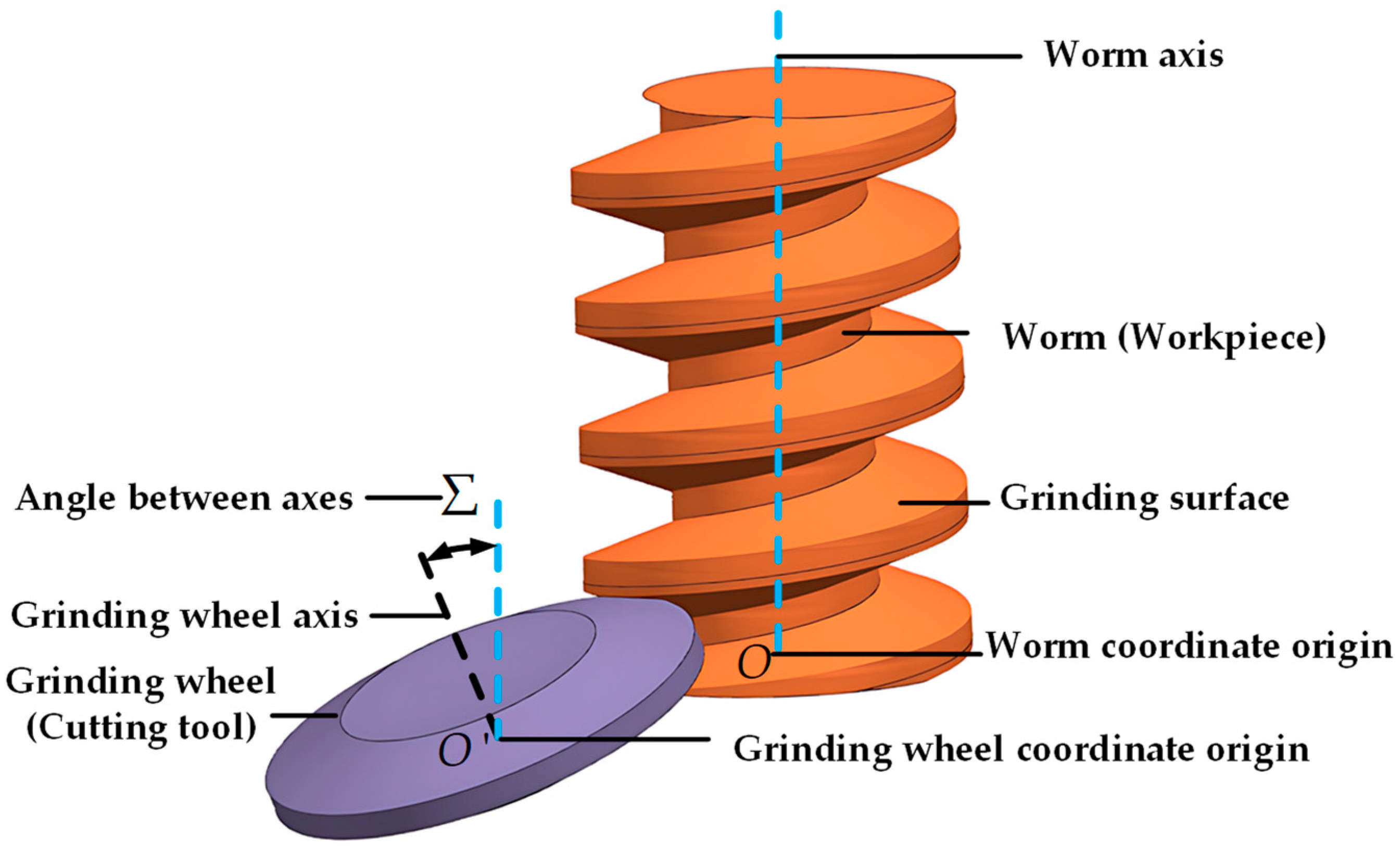
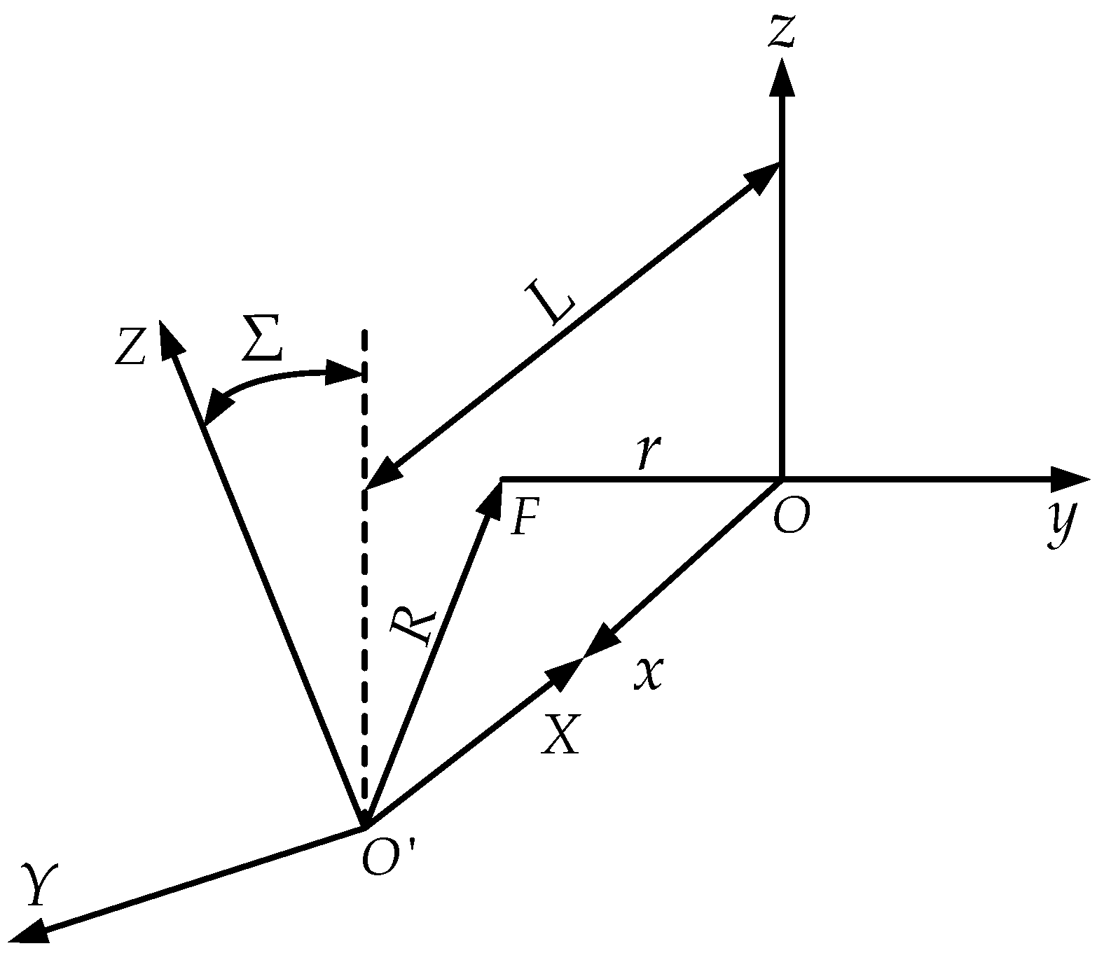
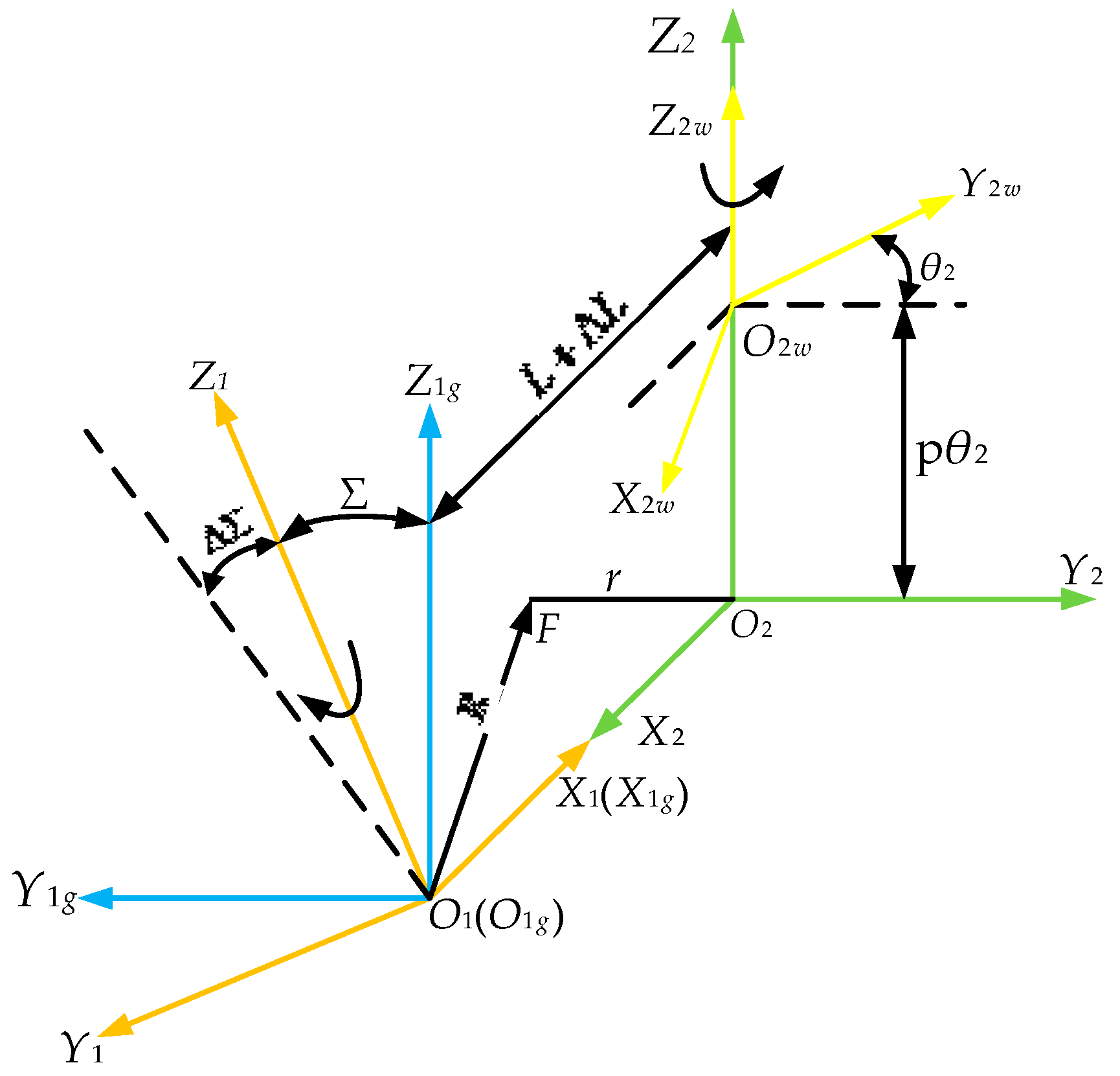
2.3. Mathematical Model of the Grinding Process of Modified ZI Worm

Figure 5 shows the structural diagram of the form grinding machine. In the process of form grinding, the grinding wheel revolves around its axis, while simultaneously feeding along the radius direction of the grinding wheel. The ZI worm also revolves around its axis and moves linearly along its own axial direction at the same time. As shown in Figure 6, is the machining coordinate system of the form grinding of the ZI worm. The coordinate system S 1 ( O 1 X 1 Y 1 Z 1 ) is fixed to the grinding wheel; the coordinate system S 2 ( O 2 X 2 Y 2 Z 2 ) is fixed to the axial movement worktable of the ZI worm; the coordinate system S 1 g ( O 1 g X 1 g Y 1 g Z 1 g ) is fixed to the base of the swivel table of the grinding wheel frame; the coordinate system S 2 w ( O 2 w X 2 w Y 2 w Z 2 w ) is fixed to the machined ZI worm. θ 2 is the rotation angle of the ZI worm, p θ 2 is the movement distance along Z 2 , p is the helix parameter, and L is the installation center distance between the grinding wheel and ZI worm. The value of the center distance L is constantly changing due to the radial feeding of the grinding wheel during the grinding, and Δ L is its change amount. In addition, the installation angle of the grinding wheel may be changed when installing the grinding wheel or during the grinding, and Δ L is its change amount.
According to the analysis of the spatial positional relationship among the fixed coordinate system of the grinding wheel and the fixed and machining coordinate systems of the ZI worm in Figure 6, the transformation matrix from the fixed coordinate system S 1 g of the grinding wheel to the fixed coordinate system S 2 of the ZI worm can be expressed as follows:
M 21 g = 1 0 0 L + Δ L 0 1 0 0 0 0 1 0 0 0 0 1
Similarly, the transformation matrix from the fixed coordinate system S 2 of the ZI worm to the machining coordinate system S 2 w of the ZI worm is expressed as follows:
M 2 w 2 = cos θ 2 sin θ 2 0 0 sin θ 2 cos θ 2 0 0 0 0 1 p θ 2 0 0 0 1
Similarly, the transformation matrix from the coordinate system S 1 of the grinding wheel to the fixed coordinate system S 1 g of the grinding wheel is expressed as follows:
M 1 g 1 = 1 0 0 0 0 cos ( Σ + Δ Σ ) sin ( Σ + Δ Σ ) 0 0 sin ( Σ + Δ Σ ) cos ( Σ + Δ Σ ) 0 0 0 0 1
From Equations (19)–(21), the transformation matrix from the coordinate system S 1 of the grinding wheel to the machining coordinate system S 2 w of the ZI worm can be deduced as follows:
M 2 w 1 = M 2 w 2 M 21 g M 1 g 1
Therefore, during the form grinding, the transformation relationship between an arbitrary point P ( X 1 , Y 1 , Z 1 ) in the coordinate system S 1 of the grinding wheel and the corresponding point P ( X 2 w , Y 2 w , Z 2 w ) in the machining coordinate system S 2 w of the ZI worm is expressed as follows:
X 2 w Y 2 w Z 2 w 1 T = M 2 w 1 X 1 Y 1 Z 1 1 T
The following expression is obtained:
X 1 Y 1 Z 1 1 T = M 12 w X 2 w Y 2 w Z 2 w 1 T
By means of Formulas (23) and (24), the mutual transformation is realized between a certain point on the grinding wheel profile and the worm-tooth surface. Suppose the parameters of the worm are given; the profile of the form grinding wheel can be obtained through the coordinate transformation on the contact surface.

3. Solving of Grinding Wheel Profile

Based on the MATLAB software, the algorithm for solving the grinding wheel profile from the modified ZI worm parameter tooth surface is studied by applying the curve interpolation method and the nonlinear equation-solving theory. The calculation flow is shown as the following Figure 7:

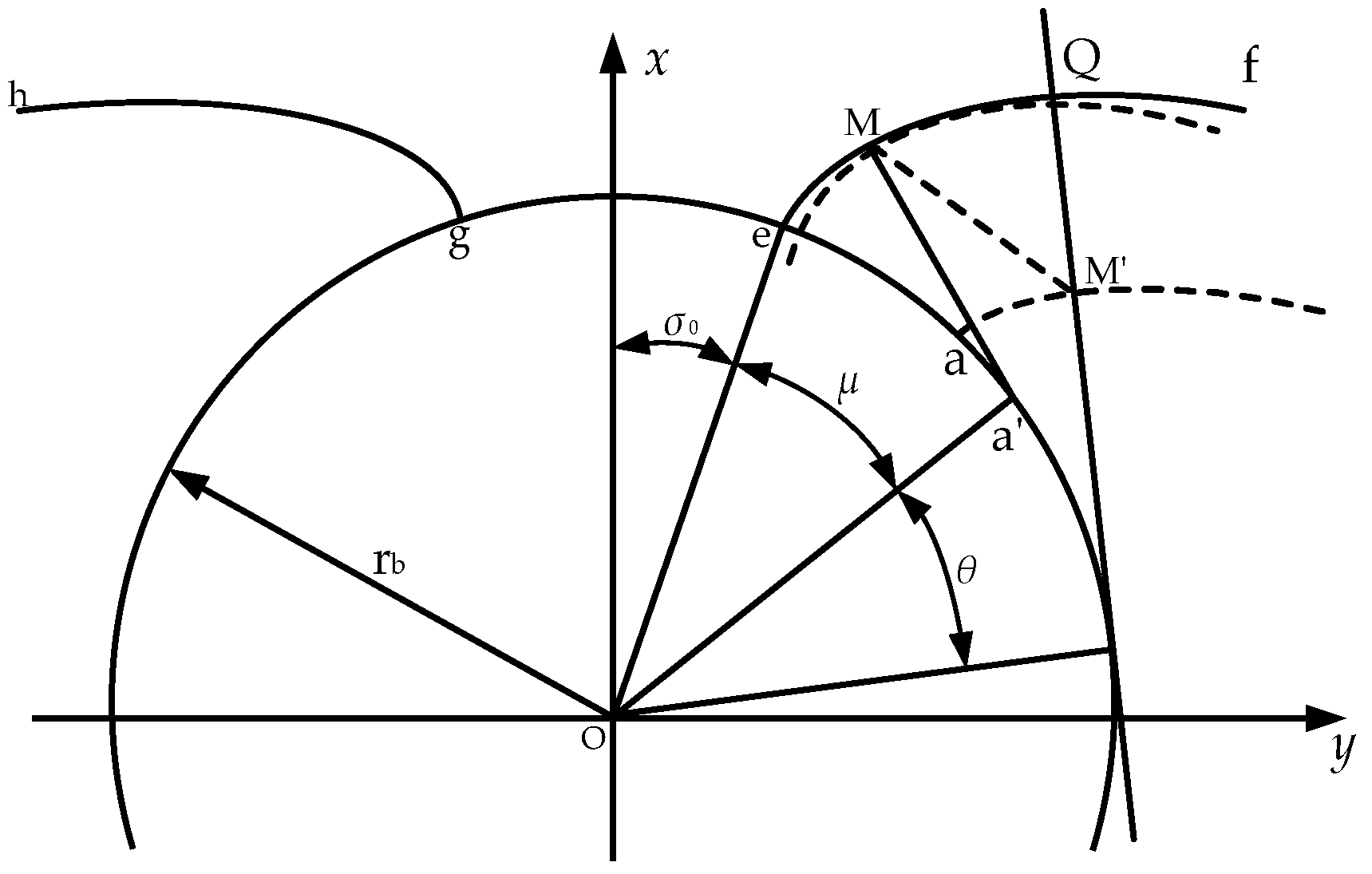
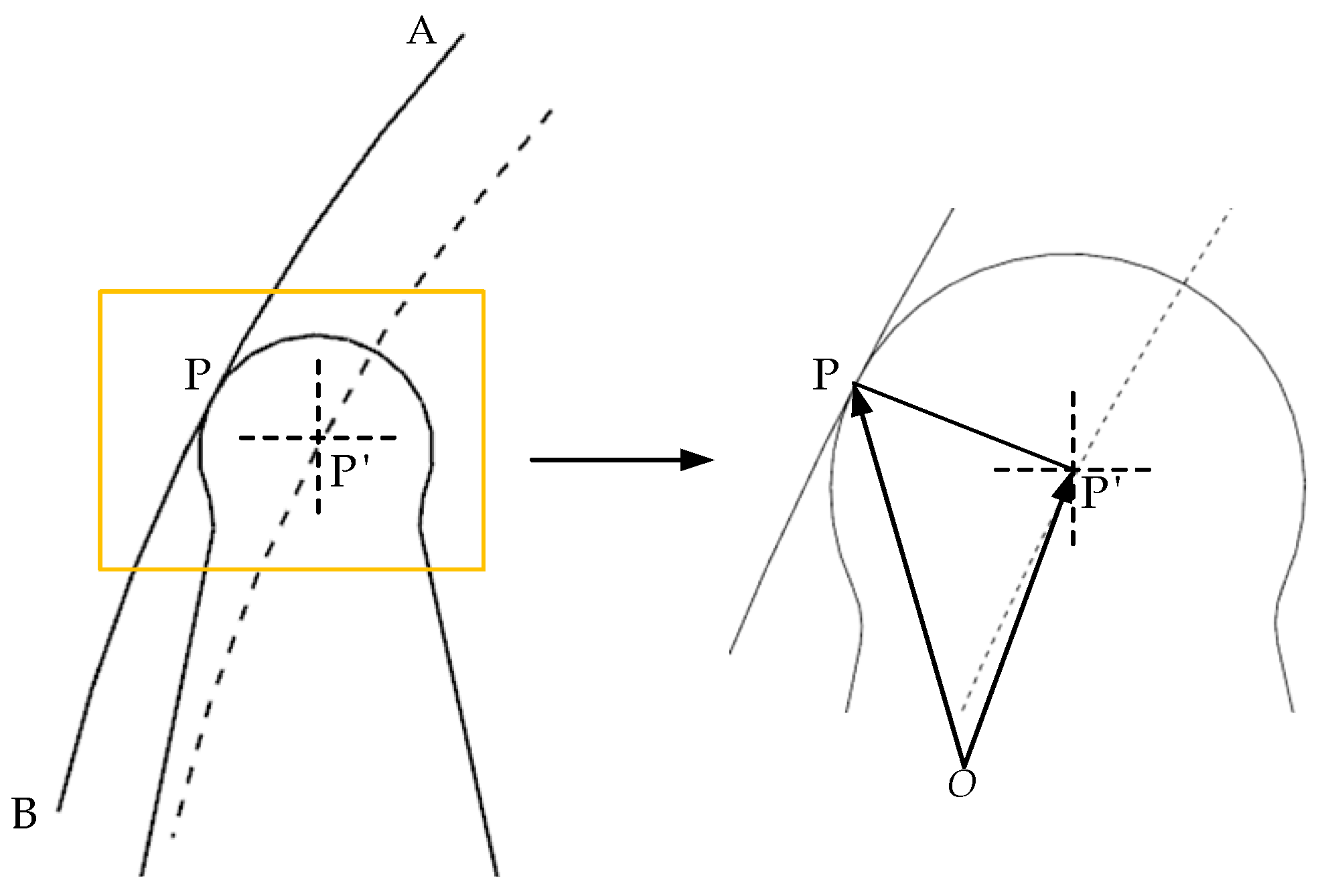
3.1. Involute Interpolation Algorithm

It is essential to figure out how to determine reasonably the division rule of the spreading angle of the involute from the starting point to the endpoint and how to calculate the coordinate positions of each point on the involute with the changing of the spreading angle accurately so as to build the model of the worm tooth surface and solve the grinding wheel profile accurately. The equal-error interpolation method and the proportional relationship between the spreading length of the involute and the spreading angle are applied to control the error. The entire curve is successively divided into several tiny straight-line segments from the initial position to the terminal position, and tangents, chords, etc., are used to approximate the involute curve. The principle is illustrated in the following Figure 8:
3 , the difference between 2 and 1 , can be regarded as the angular change Δ α of each time in the formation of the involute. Since the degree of 3 is small, the tangent points a 1 and a 2 of the generating line and the starting circle of the involute can be approximately regarded as point a . In the sector a A A , a perpendicular line to A A is drawn from point a and intersects A A at point c . The linear distance between the tangent line on A A passing through point c and the straight line A A is ε , which is the approximation error during curve interpolation. When A A is small enough, the approximation error also decreases, and the solution accuracy continuously increases. Let 2 = α k , then 1 = α k + 1 , and A A = H . According to the geometric relationship, the following expression is obtained:
( H / 2 ) 2 + ( r b α ε ) 2 = ( r b α ) 2
Δ = α k + 1 α k
By combining (25) and (26), the following expression is obtained:
Δ = 8 * r b * α k * ε / ( r b * α k )
By means of Equation (27), the relationship between the angular change value from the generation position to the end position of the involute and the approximation error is established; in addition, the number of iterations for solving the involute helicoid is determined.

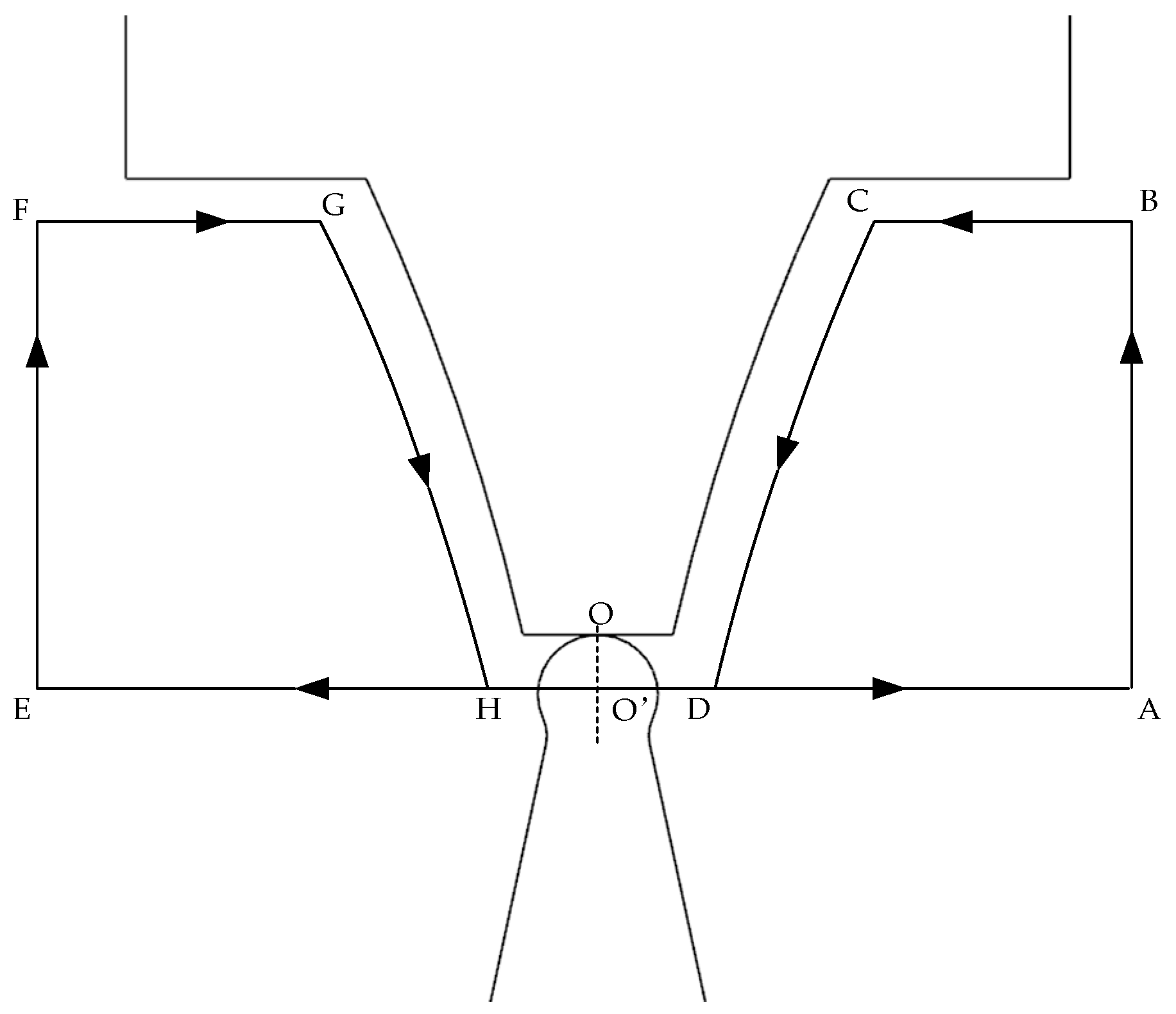
3.2. Solution of the Axial Section of the Grinding Wheel

It can be known from Formula (18) that the contact-relation formula between the grinding wheel and the worm during form grinding is a complex non-linear equation. Such equations are usually very difficult to solve by analytical methods. Therefore, the fsolve algorithm of numerical iteration is applied to obtain the solution of the approximation equation. When suitable θ is found to make the equation equal to zero, it can be considered that the contact situation between the grinding wheel and the worm at this moment is perfect. Once the calculation value of the θ is determined, a relatively accurate involute helicoid can be obtained. The solution principle is shown in Figure 9:
Suppose the contact line relationship is the objective function F ( x ) , and then consider the initial vector x 0 of θ as the starting point of the iteration, substitute the current iteration point x n into the nonlinear equation F ( x ) , thus the current-point function value F ( x n ) and the function vector are obtained. The derivative formula is approximated by the finite-difference method, as shown in Equation (28), aiming to construct an approximate Jacobian matrix to determine the iteration step-size and direction. Among them, i , j , and n are regarded as non-negative integers, h is considered as a step size approaching 0, and e j is defined as the j -th unit vector.
J ˜ ( x n ) = f i x j = f i ( x n + h e j ) f i ( x n ) h
The product of the inverse matrix J ˜ 1 ( x n ) of the approximate Jacobian matrix J ˜ ( x n ) and the function-value vector F ( x n ) is regarded as the difference value to calculate the iteration point x n + 1 , so as to determine the next iteration direction and step-size, as shown in Equation (29).
x n + 1 = x n J ˜ 1 ( x n ) F ( x n )
The convergence condition is checked to determine whether the current value of the equation is approaching 0 and whether the range of the independent-variable change is becoming stable. That is, whether the norm of the function value and the variable change are both less than the minimum threshold. If satisfied, the current variable value is output; otherwise, the iteration point x n + 1 is re-entered into the calculation process. The discrimination condition is shown in Equation (30), where p and q represents the number of equation systems and the number of unknowns, respectively.
F ( x n ) 2 = i = 1 p f i 2 ( x n ) < ϵ 1 x n + 1 x n 2 = j = 1 q ( x j , n + 1 x j , n ) 2 < ϵ 2
All the contact points on the contact line are obtained output after k times iteration is accomplished; rotation angles θ around the Z-axis corresponding to the contact line at different positions of the spreading angle are obtained. According to the number of cycles, θ is substituted into Formula (3) in turn, and the involute helicoid equation in form grinding can be obtained. Subsequently, based on Formula (24), the involute helicoid equation is subjected to coordinate transformation to obtain the components of the grinding wheel in the X , Y , and Z directions, and the expression of the axial cross-section profile of the grinding wheel can be obtained as shown in Formula (31).
R = X 2 + Y 2 Z = Z
The obtained axial cross-section profile of the grinding wheel is revolved around the rotation axis, and the resulting solid of revolution is the required form of the grinding wheel, as shown in Figure 10.
Among them, X , Y , and Z are, respectively, represented as the components of the grinding wheel in the X , Y , and Z directions.

3.3. Solution of Grinding Wheel Dressing Trajectory

As shown in Figure 11, it is the formation principle of the trajectory of the diamond roller dressing the grinding wheel. When the outer circle of the diamond roller is used to dress the grinding wheel, the arc on its side contacts the profile of the grinding wheel. Taking the center of the arc as the trajectory control point of the diamond wheel, the motion trajectory of the diamond wheel is an equidistant curve of the profile of the grinding wheel with a distance equal to the arc radius. The interpolation accuracy of the profile of the grinding wheel is controlled by adjusting the coordinate changes of the center of the arc.
Suppose the radius of the arc is r , and the center of the circle is set as P ( x , y , 0 ) . The contact point with the profile A B is assumed to be P ( x , y , 0 ) . Then the position vector of the point P on the profile of the grinding wheel is defined as O P = ( x , y , 0 ) , and the position vector of the center of the diamond wheel is regarded as O P = ( x , y , 0 ) . The tangential vector passing through the point P is expressed as follows:
O P e = ( d y d x 2 + d y 2 , d x d x 2 + d y 2 , 0 )
According to the vector relationship, the normal vector at point P is obtained as N p = ± ( O P O P ) . Due to k = ( 0 , 0 , 1 ) , the normal vector is calculated as follows:
N p = O P e × k
By means of the Equations (32) and (33), the following equations are derived:
x = x ± r d y d x 2 + d y 2 y = y r d x d x 2 + d y 2 z = 0
Among them, the tool-setting point for form grinding is regarded as the center point O of the addendum of the grinding wheel. The movement path of the center O of the diamond wheel is set as O’A→AB→BC→CD→DE→EF→FG→GH→HA, and this cycle is repeated until the required profile of the grinding wheel is dressed. The dressing trajectory is shown in Figure 12.

4. Programming and Virtual Grinding Simulation

In order to verify the accuracy of the grinding wheel profile solution theory, the calculation and output of the grinding wheel profile and dressing trajectory are carried out through computer programming. A digital virtual grinding platform is established via a 3D model to conduct a visual simulation of the grinding process to improve the parameterization, intelligence, and visualization of the grinding wheel profile. The research process is shown in the following Figure 13:

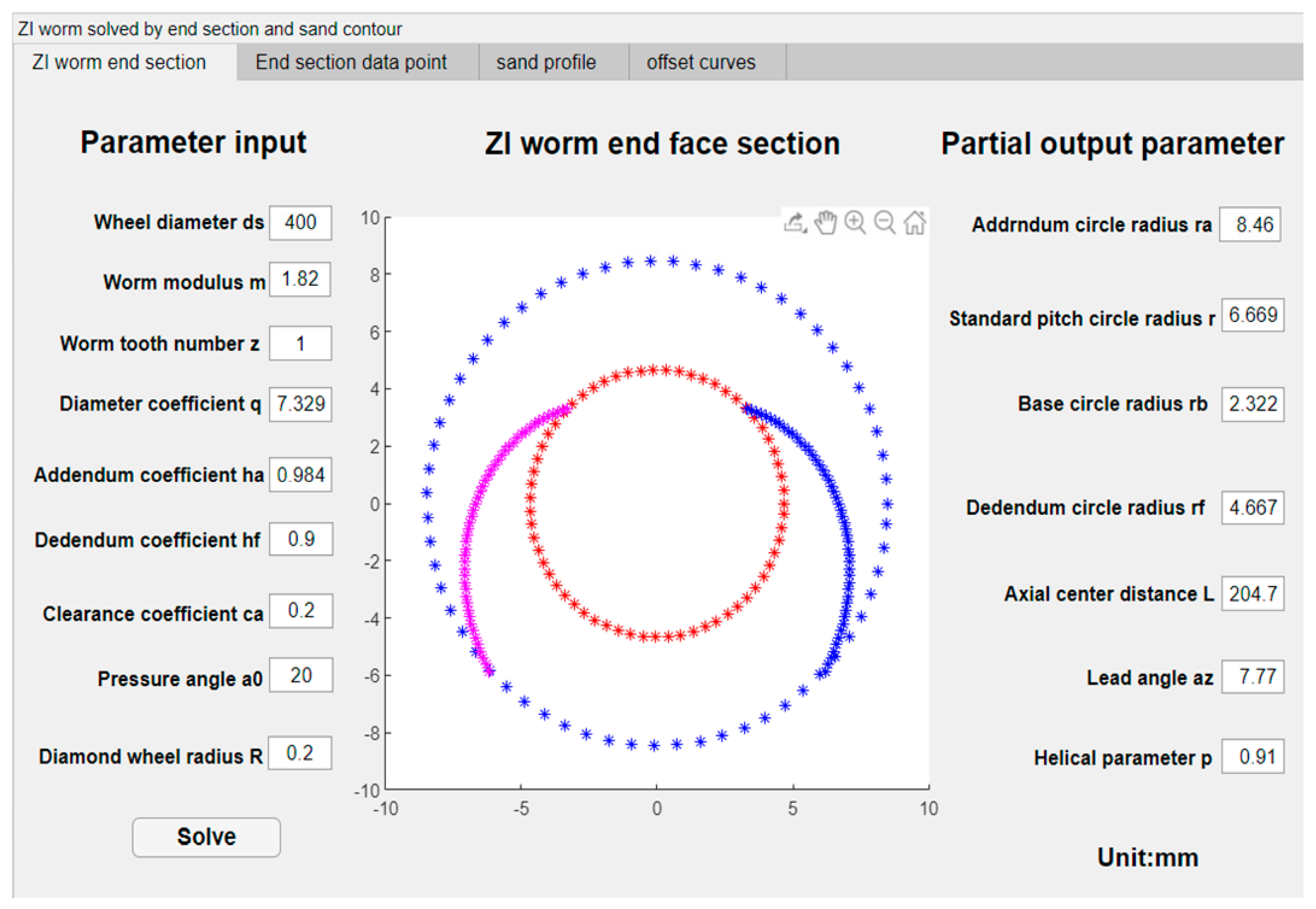
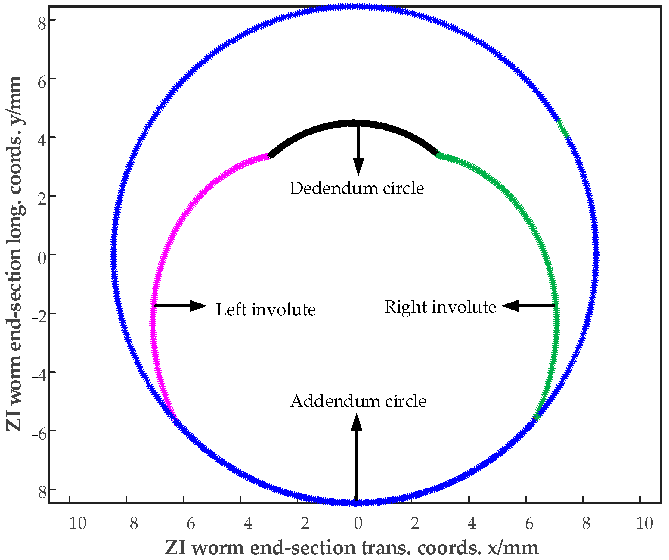
4.1. Data Extraction

MATLAB software is used as the development tool; its APP designer function is leveraged, and based on the aforementioned solution method, a software for solving the end profile of the ZI worm and axial section profile of the grinding wheel is developed, as shown in the following Figure 14:
Among them, the input parameters are as follows: grinding wheel diameter, worm module, number of worm teeth, worm characteristic coefficient, addendum coefficient, dedendum coefficient, clearance coefficient, and normal pressure angle, as shown in Table 1 below:
Input the parameters, click the “solve” button, the point positions of the end-face profile of the required worm, the point positions of the grinding wheel profile, and the point positions of the equidistant curve can be generated and extracted. Additionally, data extraction can be completed. Table 2, Table 3, and Table 4, respectively, correspond to the end-face profile of the worm, the axial profile of the grinding wheel, and the equidistant curve. They are shown in Figure 15 and Figure 16.
Based on the point positions in Table 2 and Table 3, parametric modeling of the ZI worm and the grinding wheel is performed, as shown in Figure 17.

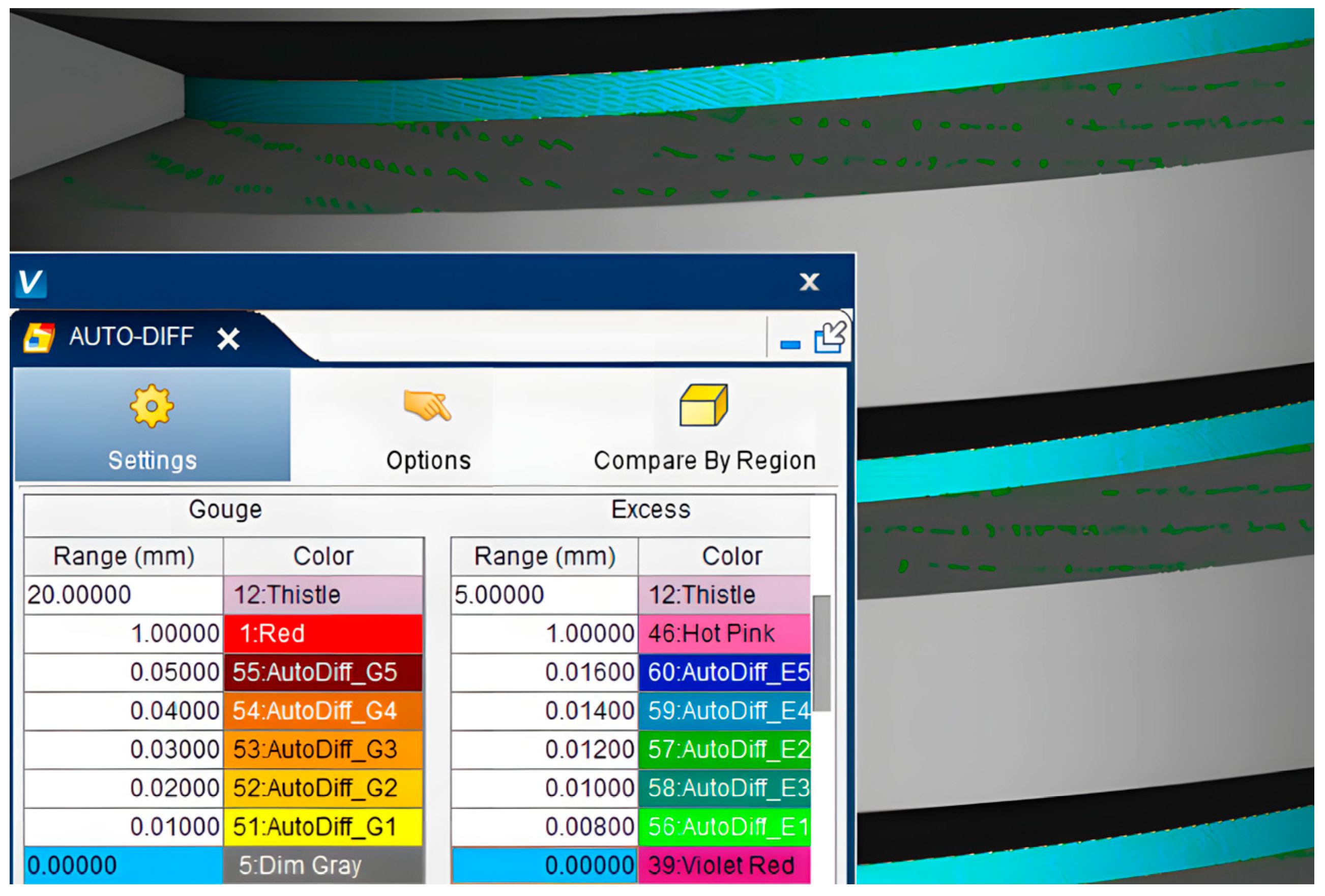
4.2. Virtual Grinding
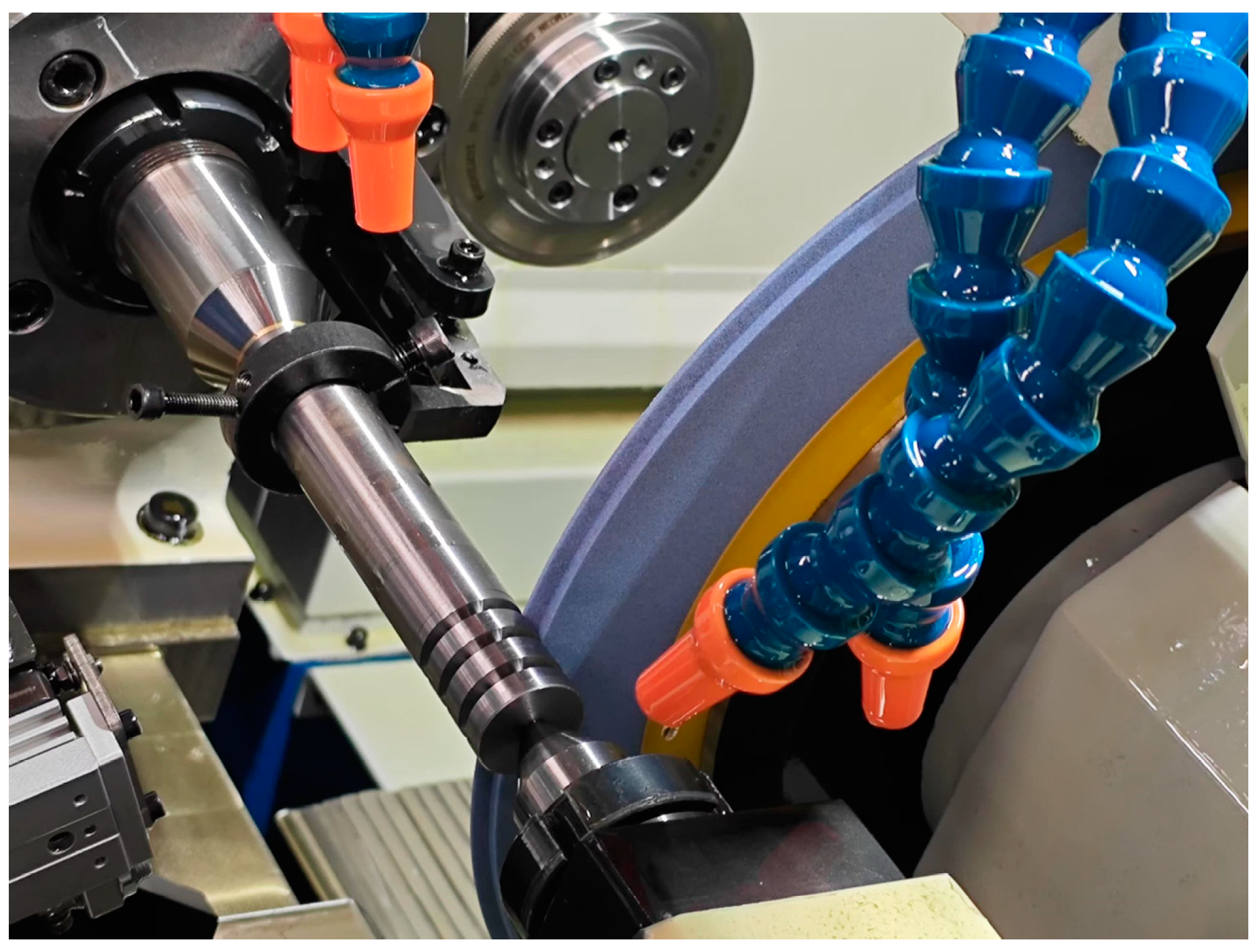
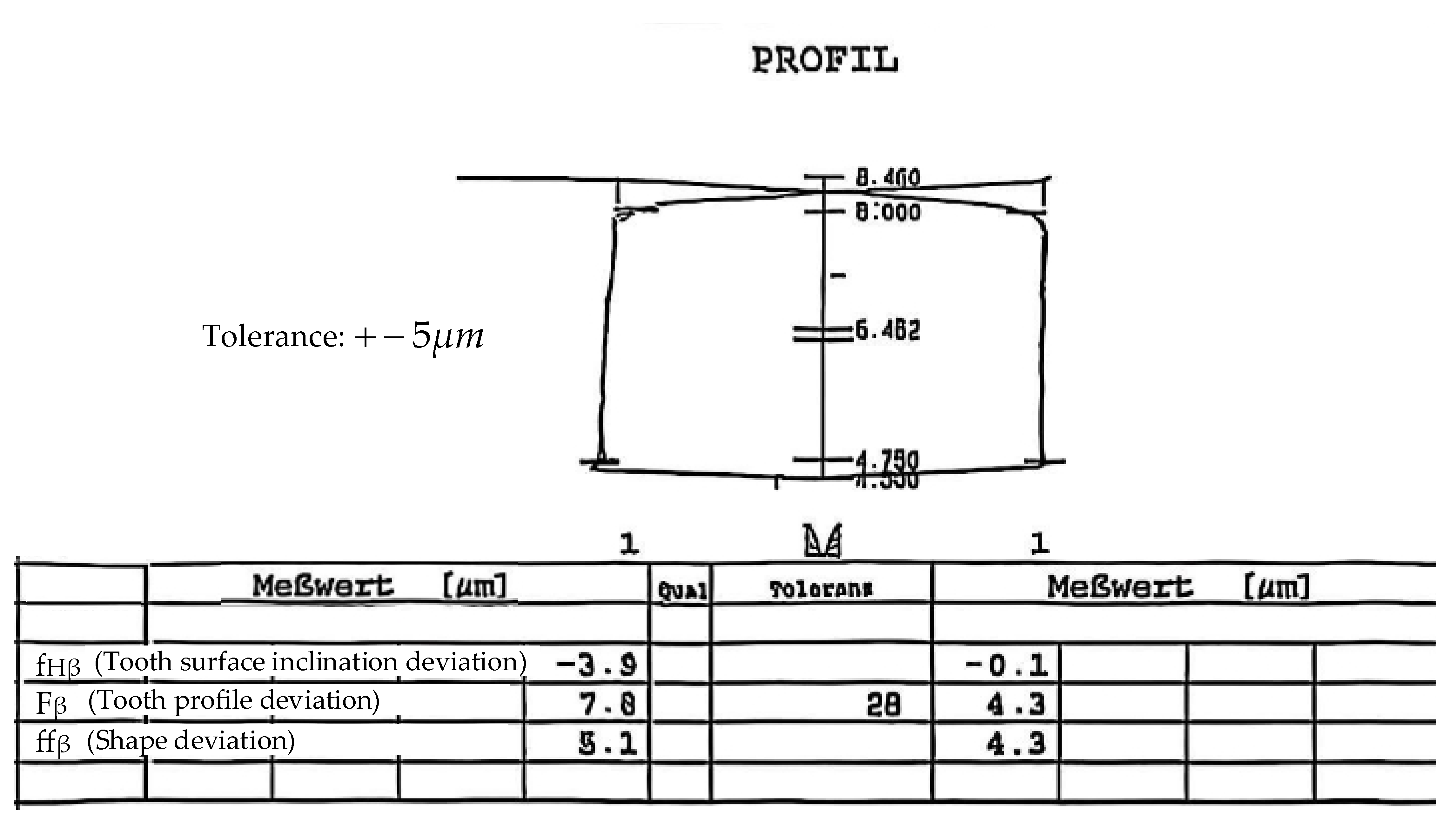
A virtual grinding simulation system is developed to complete the technological processes, such as diamond dressing of the grinding wheel and form grinding of the worm. The flow of the simulation system is shown in Figure 18. A three-dimensional solid model of the gear grinding machine is established based on VERICUT, and the constructed grinding platform is shown in Figure 19:
The “Auto-Compare” function is utilized to compare the grinding wheel obtained from the simulated machining with the constructed grinding wheel. From the comparison results, it is evident that the grinding wheel processed by the diamond wheel in the simulation is consistent with the grinding wheel model obtained from the numerical calculation, as shown in Figure 20.
Subsequently, form grinding simulation on the worm is conducted; the final result of worm machining is shown in Figure 21:
By comparing with the theoretical worm digital model, a small amount of undercutting error is detected on the tooth surface, ranging from 0.008 mm to 0.012 mm, while an error of 0.014 mm is present in the tooth groove part. On the one hand, this is a result of the accuracy loss during the three-dimensional modeling of the worm; on the other hand, it is caused by the cumulative residual error when fitting the grinding wheel profile curve. However, in the actual operation of the worm, the meshing area is the working tooth surface, and the bottom of the tooth groove scarcely participates in meshing. Therefore, the meshing performance of the worm will not be influenced by the error in the tooth groove part. Thus, a visual simulation of the actual grinding process can be offered by the method of using a diamond wheel to dress the grinding wheel and the grinding wheel for grinding.

5. Grinding Test

A grinding test is conducted on the SK-7312 CNC worm grinding machine with the Siemens numerical control system. The form grinding wheel is selected as described in Section 4 of the simulation processing based on the software. The parameters of the ZI worm in the grinding test are shown in Table 1, and the gear grinding process is shown in Figure 22.
The ground workpieces are measured on the (Klingelnberg) gear measuring center using the accompanying worm detection software. The detection results of the worm ground with the software developed by us are shown in Figure 23. From the measurement results, it can be seen that, except for the profile of the left hand tooth surface is slightly larger than 5 μm, the accuracy of the overall worm meets the requirements of precision grinding. Thus, the accuracy of the solving software and the feasibility of the grinding wheel dressing can be verified.

6. Conclusions

This study derived the grinding wheel profile tooth surface equation based on the form grinding principle. Using MATLAB, it solved the ZI worm’s end section and the grinding wheel’s axial profiles, supporting grinding wheel design and manufacture.
A software for ZI worm form grinding wheel profiles was developed. The grinding process simulation with VERICUT verified the calculation method’s practical applicability.
Through data extraction, gear grinding tests, and tooth profile accuracy detection, the effectiveness of the grinding wheel profile dressing was confirmed. Thus, the algorithm is suitable for calculating ZI worm form grinding wheel profiles.
Future experimental research can be carried out from the following three aspects:
  • Multi-parameter Experimental Exploration
Study the influence of the combinations of different worm parameters and grinding wheel parameters on the machining accuracy. Set up multiple groups of experiments, where some parameters are changed in each group. Monitor the changes in indicators, such as the tooth profile accuracy and tooth pitch error of the worm after machining and construct a parameter accuracy correlation model to provide a basis for the selection of parameters in actual production.
2.
Process Parameter Optimization Experiment
Conduct experiments on the grinding process parameters. Use the single factor experimental method to determine the relatively optimal value range of each parameter. Then, by using orthogonal or response surface experimental designs, explore the influence of the interaction of multiple parameters on the machining quality of the worm. Establish an optimization model to obtain the optimal combination of process parameters.
3.
Experimental Verification under Different Working Conditions
Simulate different working conditions in actual production, such as varying machining environment temperatures, humidity levels, and equipment accuracy grades, and carry out worm grinding experiments. Compare the machining results under different working conditions with the ideal state, analyze the influence of working condition factors on the machining accuracy and the wear of the grinding wheel, and provide a reference for controlling working conditions and the selecting equipment in actual production.

Author Contributions

Conceptualization, J.S. and J.X.; data curation, J.X.; funding acquisition, J.S.; methodology, J.S. and J.X.; investigation, J.S. and J.X.; writing—original draft, J.S. and J.X.; supervision, J.X.; writing—review and editing, J.S. All authors have read and agreed to the published version of the manuscript.

Funding

This research was funded by the National Natural Science Foundation of China (No. 52375052), the Natural Science Foundation of Henan Province (No. 242300421183), the Key R&D Program of Henan Province (No. 241111230300), and the Frontier Exploration Project of Longmen Laboratory (No. LMQYTSKT027).

Institutional Review Board Statement

Not applicable.

Informed Consent Statement

Not applicable.

Data Availability Statement

The data presented in this study are available in the article.

Conflicts of Interest

The authors declare no conflicts of interest.

References

  1. Cui, H.Y.; Tian, X.J.; Wang, D.S. Design Technique Research of Fine-forged Spur Bevel Gear Tooth Profile. Modification. Key Eng. Mater. 2010, 443, 170–176. [Google Scholar] [CrossRef]
  2. Golebski, R.; Ivandic, Z. Analysis of Modfication of Spur Gear Profile. Teh. Vjesn. 2018, 25, 643–648. [Google Scholar]
  3. Zhou, D.; Deng, X.Z.; Ren, X.Z. Study on the Parameter Influences of Gear Tooth Profile Modification and Transmission Error Analysis. Machines 2024, 12, 316. [Google Scholar] [CrossRef]
  4. Sun, Z.; Chen, S.Y.; Hu, Z.H.; Tao, X. Improved Mesh Stiffness Calculation Model of Comprehensive Modification Gears Considering Actual Manufacturing. Mech. Mach. Theory 2021, 167, 104470. [Google Scholar] [CrossRef]
  5. Yang, Y.Z.; Liu, W.L.; Yan, R.Z. Analysis of the Repairing Wheel Movement for CNC Dressing System of Formed Grinding Wheel. Adv. Mat. Res. 2012, 486, 509–514. [Google Scholar] [CrossRef]
  6. Yu, T.B.; Su, P.C.; Zhang, J.Q.; Guan, P.; Wang, W.S. A Simulation System for Grinding Based on Virtual Reality. Adv. Mat. Res. 2010, 126–128, 96–100. [Google Scholar] [CrossRef]
  7. Davim, J.P. Editorial: Machining: A bibliometric analysis. Int. J. Mach. Mach. Mater. 2024, 26, 293–295. [Google Scholar]
  8. Zhang, L.; Yao, B.; Shen, Z.H.; Zhao, W.C.; Zhou, B. Key Technology of Form Grinding Wheel’s Axis Section’s Derivation. Mech. Mach. Theory 2013, 753–755, 1557–1561. [Google Scholar] [CrossRef]
  9. Zhang, B.; Zhang, Y.; Zhang, L.J.; Li, Q.Y.; Wang, X.Y. Geometric Parameter Optimization for Axial Modification in Helical Gear Form Grinding. Machines 2024, 12, 657. [Google Scholar] [CrossRef]
  10. You, M.L.; Yao, B. Application of Mathematical Morphology in Solving the Profile of Forming Grinding Wheel. Math. Probl. Eng. 2023, 2022, 5735199. [Google Scholar] [CrossRef]
  11. Yang, S.Y.; Liang, R.J.; Chen, W.F.; Xu, P.H. Modelling and Experiment for Grinding Forces of Gear Form Grinding Considering Complete Tooth Depth Engagement. Proc. Inst. Mech. Eng. B 2022, 236, 1738–1750. [Google Scholar] [CrossRef]
  12. Xie, J.; Zhou, R.M.; Xu, J.; Zhong, Y.G. Form-truing Error Compensation of Diamond Grinding Wheel in CNC Envelope Grinding of Free-form Surface. Int. J. Adv. Manuf. Tech. 2010, 48, 905–912. [Google Scholar] [CrossRef]
  13. Xie, J.; Zheng, J.H.; Zhou, R.M.; Lin, B. Dispread Grinding Wheel Profiles for Accurate Freeform Surfaces. Int. J. Mach. Tool. Manu. 2011, 51, 536–542. [Google Scholar] [CrossRef]
  14. Tao, L.J.; Yuan, M.X.; Fang, H.F. A Pre-compensation Method for Profile Errors of Screw Rotors under Precision Form Grinding. Int. J. Adv. Manuf. Tech. 2021, 117, 3228–3239. [Google Scholar] [CrossRef]
  15. Su, J.X.; Jiang, C.; Zhang, H.; Nie, S.W. Error Analysis and Compensation of Cycloid Gear Form Grinding Based on Multi-body System Error Topology Theory. J. Braz. Soc. Mech. Sci. Eng. 2022, 44, 14. [Google Scholar] [CrossRef]
  16. Liang, D.; Hao, N.D.; Zhao, W.J.; Li, M. Grinding Wheel Profile Design and Temperature Field Analysis of the Pinion for Internal Meshing Gear with Curve Configuration. Proc. Inst. Mech. Eng. C J. Mech. Eng. Sci. 2024, 238, 4883–4895. [Google Scholar] [CrossRef]
  17. Li, Y.; Li, G.; Wang, Z.H.; Zhu, W.M. A Form-grinding Wheel Optimization Method for Helical Gears Based on a PSO-SVM Model. Precis. Eng. J. Int. Socs. Prec. Eng. Nanotechnol. 2024, 88, 664–673. [Google Scholar] [CrossRef]
  18. Jiang, L.; Yang, Z.H.; Li, Y.; Ding, G.F.; He, X. An Optimized Calculation Method of the Grinding Wheel Profile for the Helical Flute Forming Grinding. Int. J. Adv. Manuf. Technol. 2024, 132, 1649–1664. [Google Scholar] [CrossRef]
  19. He, K.; Li, G.L.; Du, Y.B.; Tang, Y. A Digital Method for Calculation the Forming Cutter Profile in Maching Helical Surface. Int. J. Mech. Sci. 2019, 155, 370–380. [Google Scholar] [CrossRef]
  20. Davim, J.P. Machining: Fundamentals and Recent Advances; Springer: Cham, Switzerland, 2008. [Google Scholar]
  21. Jackson, M.J.; Davim, J.P. Machining with Abrasives; Springer: Cham, Switzerland, 2011. [Google Scholar]
Figure 1. Three-dimensional structural diagram of the workpiece and the grinding wheel.
Applsci 15 02767 g001
Figure 2. End-face section of involute ZI worm.
Applsci 15 02767 g002
Figure 3. Tooth profile modification curve.
Applsci 15 02767 g003
Figure 4. The positional relationship between the ZI worm and the grinding wheel.
Applsci 15 02767 g004
Figure 5. Form grinding machining coordinate system.
Applsci 15 02767 g005
Figure 6. Form grinding coordinate system.
Applsci 15 02767 g006
Figure 7. Calculation flow chart.
Applsci 15 02767 g007
Figure 8. Formation process of involute.
Applsci 15 02767 g008
Figure 9. Solution principle of θ .
Applsci 15 02767 g009
Figure 10. Axial cross-section profile of the grinding wheel.
Applsci 15 02767 g010
Figure 11. Trajectory of grinding wheel dressing with diamond wheel.
Applsci 15 02767 g011
Figure 12. Grinding wheel dressing trajectory.
Applsci 15 02767 g012
Figure 13. The flow of programming and virtual grinding simulation.
Applsci 15 02767 g013
Figure 14. Software overall interface.
Applsci 15 02767 g014
Figure 15. Modified end profile of ZI worm.
Applsci 15 02767 g015
Figure 16. The axial profile of the grinding wheel and its equidistant curve.
Applsci 15 02767 g016
Figure 17. 3D modeling: (a) modified ZI worm; (b) grinding wheel.
Applsci 15 02767 g017
Figure 18. Simulated machining process.
Applsci 15 02767 g018
Figure 19. Gear virtual grinding simulation based on VERICUT.
Applsci 15 02767 g019
Figure 20. Simulation results of grinding wheel dressed by diamond wheel.
Applsci 15 02767 g020
Figure 21. Simulation results of form grinding worm.
Applsci 15 02767 g021
Figure 22. ZI worm grinding.
Applsci 15 02767 g022
Figure 23. Software solved grinding wheel ground worm detection report.
Applsci 15 02767 g023
Table 1. Basic parameters of the ZI worm.
ParametersSymbolValue
Wheel diameter (mm) d s 400
Worm modulus (mm) m 1.82
Worm tooth number (°) z 1
Diameter coefficient q 7.329
Addendum coefficient h a 0.984
Dedendum coefficient h f 0.9
Clearance coefficient c a 0.2
Pressure angle (°) a 0 20
Diamond wheel radius (mm) R 0.2
Table 2. Profile points of the right hand part of the involute on the end-face profile (unit: mm).
xy xy xy
12.9054.644113.5344.527214.1604.328
22.9684.636123.5974.511224.2224.303
33.0304.627133.6604.494234.2844.278
43.0934.618143.7234.476244.3464.252
53.1564.607153.7854.457254.4084.225
63.2194.596163.8484.437264.4694.197
73.2824.584173.9114.417274.5314.169
83.3454.571183.9734.396284.5924.140
93.4084.557194.0364.374294.6524.110
103.4714.542204.0984.351304.7134.079
Table 3. Profile points of the right hand part of the grinding wheel (unit: mm).
xy xy xy
10.667198.903110.762198.643210.854198.389
20.677198.876120.771198.617220.863198.364
30.686198.850130.780198.592230.872198.339
40.696198.824140.790198.566240.881198.314
50.705198.798150.799198.541250.890198.289
60.715198.772160.808198.515260.900198.264
70.724198.746170.817198.490270.909198.239
80.734198.720180.827198.464280.918198.214
90.743198.694190.836198.439290.927198.190
100.752198.668200.845198.414300.936198.165
Table 4. Right hand coordinate points of the equidistant curve part (unit: mm).
xy xy xy
10.855198.971110.950198.711211.042198.457
20.865198.945120.959198.686221.051198.432
30.874198.919130.968198.660231.060198.407
40.884198.892140.978198.634241.069198.382
50.893198.866150.987198.609251.078198.357
60.903198.840160.996198.584261.087198.332
70.912198.814171.005198.558271.097198.308
80.921198.788181.015198.533281.106198.283
90.931198.763191.024198.508291.115198.258
100.940198.737201.033198.482301.123198.234
Disclaimer/Publisher’s Note: The statements, opinions and data contained in all publications are solely those of the individual author(s) and contributor(s) and not of MDPI and/or the editor(s). MDPI and/or the editor(s) disclaim responsibility for any injury to people or property resulting from any ideas, methods, instructions or products referred to in the content.

