Article

Influence of Crank Angle Offset on the Mechanical Performance of Different Hydrogen-Fueled Opposed-Piston Engine Architectures

by
Andrea Piergiacomi
*,
Saverio Giulio Barbieri
,
Valerio Mangeruga
and
Matteo Giacopini
*
Engineering Department “Enzo Ferrari”, University of Modena and Reggio Emilia, Via Vivarelli 10, 41125 Modena, Italy
*
Authors to whom correspondence should be addressed.
Appl. Sci. 2025, 15(5), 2537; https://doi.org/10.3390/app15052537
Submission received: 5 February 2025 / Revised: 17 February 2025 / Accepted: 23 February 2025 / Published: 26 February 2025
(This article belongs to the Section Mechanical Engineering)

Abstract

:
Decarbonization of the automotive sector is essential to achieve global climate goals, as passenger cars contribute a substantial share of CO2 emissions. This research project focuses on the preliminary design of an innovative 2-stroke hydrogen-fueled opposed-piston engine, offering a promising solution for reducing emissions from passenger cars. Hydrogen enables clean combustion due to its carbon-free nature and allows the possibility of nearly-zero NOx emissions when burned in an ultra-lean mixture. Although the ultra-lean mixture inevitably leads to a significant drop in performance, the opposed-piston engine architecture offers a potential solution for maintaining power output and overall dimensions comparable to traditional internal combustion engines. The study addressed the global balancing of the engine. Unlike conventional engines, the opposed-piston engine presents non-trivial challenges, such as the interaction between the two crankshafts. Two engine architectures are addressed: 3-cylinder and 4-cylinder.

1. Introduction

The transport sector accounted for 29% of CO2 emissions in 2022 in the U.S. and Europe, making it one of the main contributors to greenhouse gas emissions and air pollution. Notably, about half of these emissions came from passenger cars, underscoring their significant role in the overall carbon footprint of the transport sector. This statement makes it clear how necessary drastic decarbonization of the transport sector is. After intense debate, the European Union has imposed a reduction of 55% in CO2 emissions from passenger cars and vans by 2030 and aims for complete carbon neutrality by 2050, with the goal of becoming the world’s first climate-neutral continent [1,2,3,4].
Achieving an ecological transition within the transport sector remains one of the most critical challenges for meeting global environmental sustainability targets. Among the potential solutions, electric propulsion is currently the most promising way to reach zero emissions, especially for passenger cars and vans. However, the widespread adoption of electric vehicles (EVs) presents significant obstacles, primarily due to the requirement to replace all thermal energy derived from fossil fuels with electricity by renewable sources, necessitating extensive development of energy infrastructure. Additionally, the production of batteries and electric motors depends on metals and minerals, such as lithium, cobalt, and rare earth elements, which are predominantly sourced from a limited number of countries, including China, Chile, Australia, the United States, and Argentina. This reliance on specific geographic regions also has considerable implications for global geopolitics [1,5].
From this perspective, internal combustion engines still offer an excellent solution for a rapid transition toward zero emissions. The key to this technology is represented by alternative fuels, such as e-fuels, hydrogen, and ammonia [6]. Although hydrogen enables clean combustion due to its carbon-free nature, it presents a range of non-trivial technological challenges. One of the primary issues derives from its low density. In fact, when hydrogen is injected into the intake manifold (port fuel injection), an approximate 30% reduction in volumetric efficiency can be observed compared to gasoline. To maintain comparable performance levels, direct injection is necessary. This is still the case even if it could jeopardize the integrity of the engine, since due to the wide flammability range of hydrogen, it cannot be injected with the intake valves open to avoid possible backfire [7].
NOx formation during hydrogen combustion still persists despite the absence of carbon in hydrogen molecules, as it depends solely on oxygen and nitrogen in the atmosphere and is not related to the type of fuel. NOx formation is strictly linked to the combustion temperature, which can be reduced by using a lean mixture. Now, the wide flammability range of hydrogen becomes a significant advantage, enabling the use of ultra-lean mixtures (λ > 2.5) and leading to nearly-zero NOx emissions. However, operating with such ultra-lean mixtures inevitably leads to a significant drop in specific performance [8].
The challenges mentioned above pave the way for the investigation into new engine architectures or the revisiting of shelved designs [9]. One architecture that was very popular in the aeronautical and marine sectors in the nineteenth and twentieth centuries is the two-stroke opposed-piston (OP) engine [10]. An OP engine consists of two crank mechanisms that share the same cylinder with pistons that move in opposite directions (Figure 1). Specifically, one piston manages the intake phase and the other the exhaust phase by appropriately opening and closing suitable intake and exhaust ports. The movement of these pistons is mainly managed in two ways: with a shaft and a system of connecting rods and levers, or with two crankshafts, one for each crank mechanism, which are mechanically connected using gears, belts, or chains. In this work, attention was focused on the two-shaft configuration.
Two-stroke OP engines were first developed in Germany during the late 19th century and later refined in various countries for numerous applications. Their appeal lay in their straightforward manufacturability, high power-to-weight ratio, and competitive efficiency. These attributes enabled two-stroke OP engines to find widespread use in fields such as aviation, marine propulsion, military vehicles, heavy-duty trucks, and locomotives, securing their relevance through much of the 20th century.
Despite their advantages, two-stroke OP engines have encountered heavy issues related to emissions control, fuel economy, cost-effectiveness, and durability [11]. Over time, four-stroke engines have proven to be more capable of addressing these issues, leading to their dominant position in the global engine market [10,12]. Nevertheless, the application of hydrogen as fuel can open new design strategies for the use of OP engine architectures, as they allow for more air to be introduced into the combustion chamber than conventional reciprocating engines. Furthermore, the 2-stroke operating cycle helps to mitigate performance losses associated with ultra-lean combustion. The relationship between hydrogen and OP engines is therefore mutually beneficial: the 2-stroke OP architecture enables specific power outputs comparable to those of 4-stroke conventional gasoline engines, while hydrogen combustion allows the OP engine to operate with significantly reduced emissions [13]. Although this architecture has historically been used with conventional fuels such as gasoline or diesel, it is also suitable for alternative fuels beyond hydrogen, such as e-fuels and ammonia. However, using them in an OP engine may not provide a significant advantage as e-fuels are not carbon free and ammonia does not allow the use of ultra-lean combustion strategies due to its low flammability [14,15,16].
With the relevance of the aforementioned framework, this study aims to analyze the influence of different parameters on the crankshaft balancing of an OP engine.
In the literature, several studies propose methodologies for assessing the balancing of various four-stroke engines. For example, Heifetz et al. [17] and Dagna et al. [18] focus on developing an analytical model for the balancing of a traditional crankshaft. However, they do not consider OP architecture. Changming et al. [19] investigate the dynamic behavior of an OP engine to evaluate its overall balance, but their study examines a configuration with a single crankshaft controlling both pistons. This latter configuration is fundamentally different from the one analyzed in the present paper, which addresses two separate crankshafts, each dedicated to its respective crank mechanism.
For four-stroke engines, the main parameters influencing crankshaft balancing are generally the number of cylinders, the angle between crank throws, and the engine configuration (e.g., inline, V, or boxer).
This article specifically examines the number of cylinders and the angle between crank throws, while the configuration is disregarded, as only inline OP engines are considered. However, when dealing with OP engines, additional parameters come into play. In particular, this study also takes into account a possible offset between the two crankshafts and their direction of rotation, which can be either co-rotating or counter-rotating.
The present paper aims to establish an analytical methodology for evaluating the balancing of an OP engine by considering the four aforementioned parameters. It is important to emphasize that this study does not focus on any specific engine but instead provides a generalized framework, particularly useful in the early stages of the design process. The novelty of this study does not lie in the general balancing of internal combustion engines, as this topic has been extensively covered in the literature, but rather in the analysis of a specific architecture (OP engine), with a particular focus on the interaction between the two crankshafts and the influence of the offset angle. To the authors’ best knowledge, no previous studies in the literature have specifically addressed this aspect, highlighting the gap that this research aims to fill.
The paper is organized as follows. First, Section 2 “Problem Description” outlines the criteria used to evaluate crankshaft balancing and introduces the four key parameters considered in the analysis. Then, Section 3 “Model Description” presents the analytical model developed for this study. Next, Section 4 “Results” examines how each parameter influences engine balancing. Finally, the paper concludes with a summary of key findings and final remarks.

2. Problem Description

This section outlines the criteria and parameters adopted in the analysis, explaining their rationale and their influence on the system balancing.

2.1. Engine Balancing Criteria

The balancing of an internal combustion engine is closely related to the kinematics of the crank mechanism [20]. The movement of the components generates forces that are transmitted to the main journals and, subsequently, to the engine mounts. Improper balancing can lead to undesirable phenomena such as excessive wear, unexpected failures, vibrations, and increased noise [20]. Therefore, balancing is essential to ensure optimal operation of the system. Vibrations in an internal combustion engine are not only caused by crankshaft imbalance but also by other factors, such as clearances or wear of moving components. This aspect has not been analyzed in detail, as the focus has been on reducing crankshaft imbalance, which is the first step in minimizing vibrations.
The inertial forces generated by the crank mechanism motion can be split into two main components: centrifugal and reciprocating forces.
Centrifugal inertial forces are associated with rotating masses: the crankpin, the crank webs, the big end bearing, and the rotating portion of the connecting rod (big end). For a single crank mechanism, the magnitude of this force is defined by the equation:
F r o t = ω 2 r ( m c , r o t + m c p + m c w 1 r c w 1 r + m c w 2 r c w 2 r ) ,
where ω is the angular velocity of the engine, r is the crank radius, m c , r o t is the mass of the rotating portion of the connecting rod (big end and bearing), m c p is the crankpin mass, m c w is the mass of the crank web, and r c w is the crank web center of mass radius. Balancing in terms of centrifugal forces is achieved when the following conditions are met:
  • the center of mass of the system lies on the crankshaft axis of rotation which for multi-cylinder architectures, with a generic number of cylinders n c m , means that the vector sum of the centrifugal forces, F r o t , generated by each crank mechanism is zero:
    F r o t = i = 1 n c m F r o t , i
  • the vector sum of the moments generated by the centrifugal forces of each crank mechanism composing the multicylinder architecture, M r o t , is zero. Specifically, given any point along the crankshaft axis, each moment is obtained multiplying the centrifugal force by its respective lever arm with respect to the considered point, b i :
    M r o t = i = 1 n c m F r o t , i × b i
Reciprocating inertial forces arise from reciprocating masses: the piston, the pin, the piston rings, and the reciprocating portion of the connecting rod (small end). For a single crank mechanism, the magnitude of this force is defined by the equation:
F r e c = m r e c ω 2 r ( c o s θ + λ c o s 2 θ ) ,
where m r e c is the sum of the reciprocating masses, ω is the angular velocity of the engine, r is the crank radius, θ is the crank angle, and λ is the connecting rod ratio defined as λ = r l c where l c is the connecting rod length. Equation (4) consists of the sum of two terms and, for the purpose of studying engine balancing, it is convenient to analyze their contributions separately:
F r e c = m r e c ω 2 r c o s θ ,
which represents the first-order reciprocating force and:
F r e c = m r e c ω 2 r λ c o s 2 θ ,
which represents the second-order reciprocating force.
These forces are represented by vectors aligned with the cylinder axis with a variable amplitude function of the crank angle. However, this representation is not optimal for balancing analysis, since it requires complex calculations to define the level of imbalance for a specific engine configuration. A more effective representation exploits the harmonic nature of Equations (5) and (6). In fact, the first-order reciprocating force can be considered as the resultant of two vectors I 1 and I 2 , counter-rotating one with respect to the other, with angular velocity | ω | , arranged such that they always remain symmetrical with respect to the cylinder axis and having a magnitude:
I 1 = I 2 = 1 2 m r e c ω 2 r .
Similarly, the second-order reciprocating force can be considered as the resultant of two vectors I 1 and I 2 analogous to I 1 and I 2 but with angular velocity | 2 ω | and a magnitude:
I 1 = I 2 = 1 8 m r e c 2 ω 2 r λ .
In this way, for the single i-th crank mechanism, the reciprocating forces can be decomposed into four rotating/counter-rotating vectors: the rotating portion of the first-order reciprocating forces ( F r e c , r , i ) , the counter-rotating portion of the first-order reciprocating forces ( F r e c , c r , i ) , the rotating portion of the second-order reciprocating forces ( F r e c , r , i ) , and the counter-rotating portion of the second-order reciprocating forces ( F r e c , c r , i ) . Therefore, for balancing calculations, reciprocating forces can be treated similarly to centrifugal forces [20,21,22]. In particular, for multi-cylinder architectures the four total forces F r e c , r I , F r e c , c r I , F r e c , r I I , and F r e c , c r I I and the four total moments M r e c , r I , M r e c , c r I , M r e c , r I I , and M r e c , c r I I must be evaluated.

2.2. Design Parameters

Four design parameters were considered. The first two also apply to generic reciprocating engines and are closely related to the geometry of every single crankshaft that makes up the overall architecture. In contrast, the latter two specifically concern the interaction between the two crankshafts in the OP architecture.

2.2.1. Number of Cylinders

Since the number of cylinders substantially changes the engine dynamic behavior, two different architectures were addressed in this discussion:
  • 3-cylinder;
  • 4-cylinder.
These two configurations were selected because the single crankshaft of an OP engine can be considered as a crankshaft of a conventional inline engine. Consequently, the choice has been driven by the intention to consider the most widely used inline engine configurations, specifically the 3-cylinder and 4-cylinder inline engines.
The number of cylinders significantly influences the engine balancing because it affects the forces generated during the motion of each individual crankshaft.

2.2.2. Angle Between Crank Throws

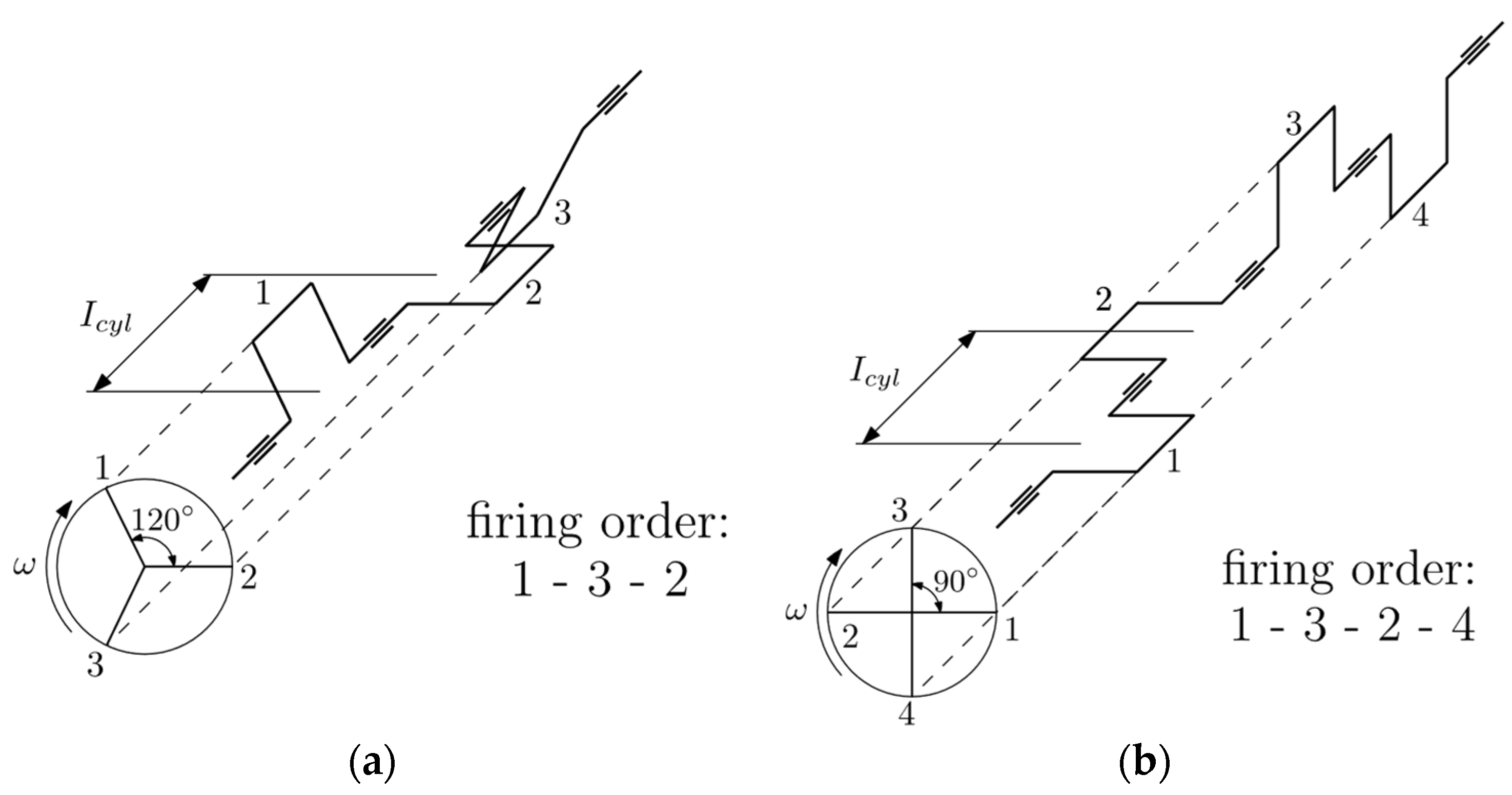
The angle between the crank throws, β , contributes, together with the firing order, to the definition of the final configuration of the crankshaft geometry and it is usually related to the number of cylinders. In fact, to obtain the most regular torque output, the angle between the crank throws is given by the equation:
β = θ c y c l e N ,
where θ c y c l e is the engine cycle duration expressed in crank angle and N is the number of cylinders. Considering the two cases addressed in the present contribution, the β angles are:
  • β = 120 ° for the 3-cylinder crankshaft,
  • β = 90 ° for the 4-cylinder crankshaft.
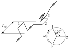
Figure 2 depicts the schematics of the two engine architectures once suitable firing orders are defined.
Table 1 shows the imbalance of the two analyzed configurations calculated considering the vector sum of the forces and of the moments, decomposed into the four components of the reciprocating forces. Note that in all configurations the result of the forces is zero. Therefore, as the equilibrium of forces does not contribute additional insights to the analysis, the discussion will henceforth focus exclusively on the equilibrium of moments. Discussions about centrifugal forces were also ignored in the following, as they can always be balanced by counterweights regardless of the number of cylinders or the angle between crank throws.

2.2.3. Direction of Rotation of the Crankshafts

While the previous parameters may be applied to any type of reciprocating engine, the following one is specific to the OP architecture. In fact, the interaction between the two crankshafts offers an additional possibility: the imbalance of one crankshaft could potentially compensate for the imbalance of the other, depending on their direction of rotation.
Therefore, another design parameter is the direction of rotation of the two crankshafts, which can be co-rotating or counter-rotating. If the direction of rotation of one crankshaft is fixed, the other can either rotate in the same direction, referred to as co-rotating, or in the opposite direction, in which case they are called counter-rotating.
There is nothing that constrains the direction of rotation of the two shafts in terms of in-cylinder fluid dynamics, and both solutions can be feasible by suitably connecting each other by gears, belts, or chain transmission. However, the direction of rotation of the two crankshafts is important from the perspectives of both structural integrity and NVH response.
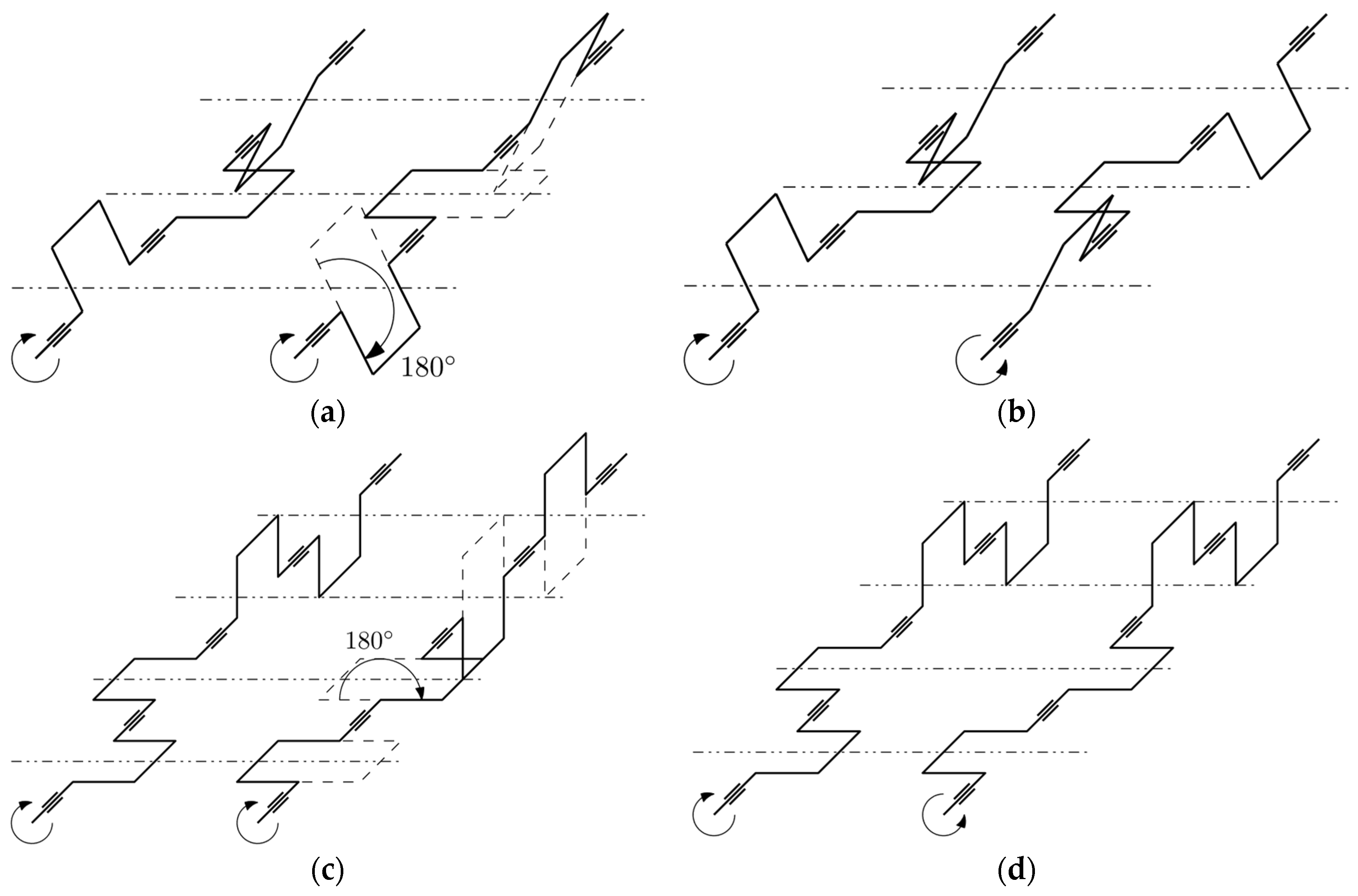
The substantial difference between the two configurations is that in the co-rotating shafts configuration, the two crankshafts are identical and phased each other by 180°, while in the case of counter-rotating shafts, the two crankshafts are symmetrical with respect to the plane orthogonal to the cylinder axes (Figure 3).

2.2.4. Offset Angle Between the Two Crankshafts

The OP engine combines the advantage of piston-controlled ports with the benefit of unidirectional scavenging [7]. The optimization of the scavenging process depends on the height of the ports and the angular offset between the intake and exhaust crankshafts (Figure 4) [23]. The offset angle, α , is defined as the phase shift of the exhaust crankshaft relative to the intake crankshaft. A positive angle indicates that the exhaust piston is in advance, and it reaches the dead centers before the intake piston.
Since the ports are opened and closed by the piston motion, the opening profile is symmetric with respect to both top and bottom dead centers. For this reason, the exhaust ports must be greater than the intake ports to ensure they open earlier and allow the exhaust gases to exit. However, with zero angular offset, the intake and exhaust ports reach their maximum opening simultaneously, when the pistons are at the BDC. This not only causes the exhaust ports to open earlier but also delays their closure, resulting in fresh charge losses through the exhaust. Disregarding port height, a positive offset delays the opening, and consequently the closing of the intake ports relative to the exhaust ports. This reduces the amount of fresh charge lost through the exhaust and increases the trapping efficiency [23].
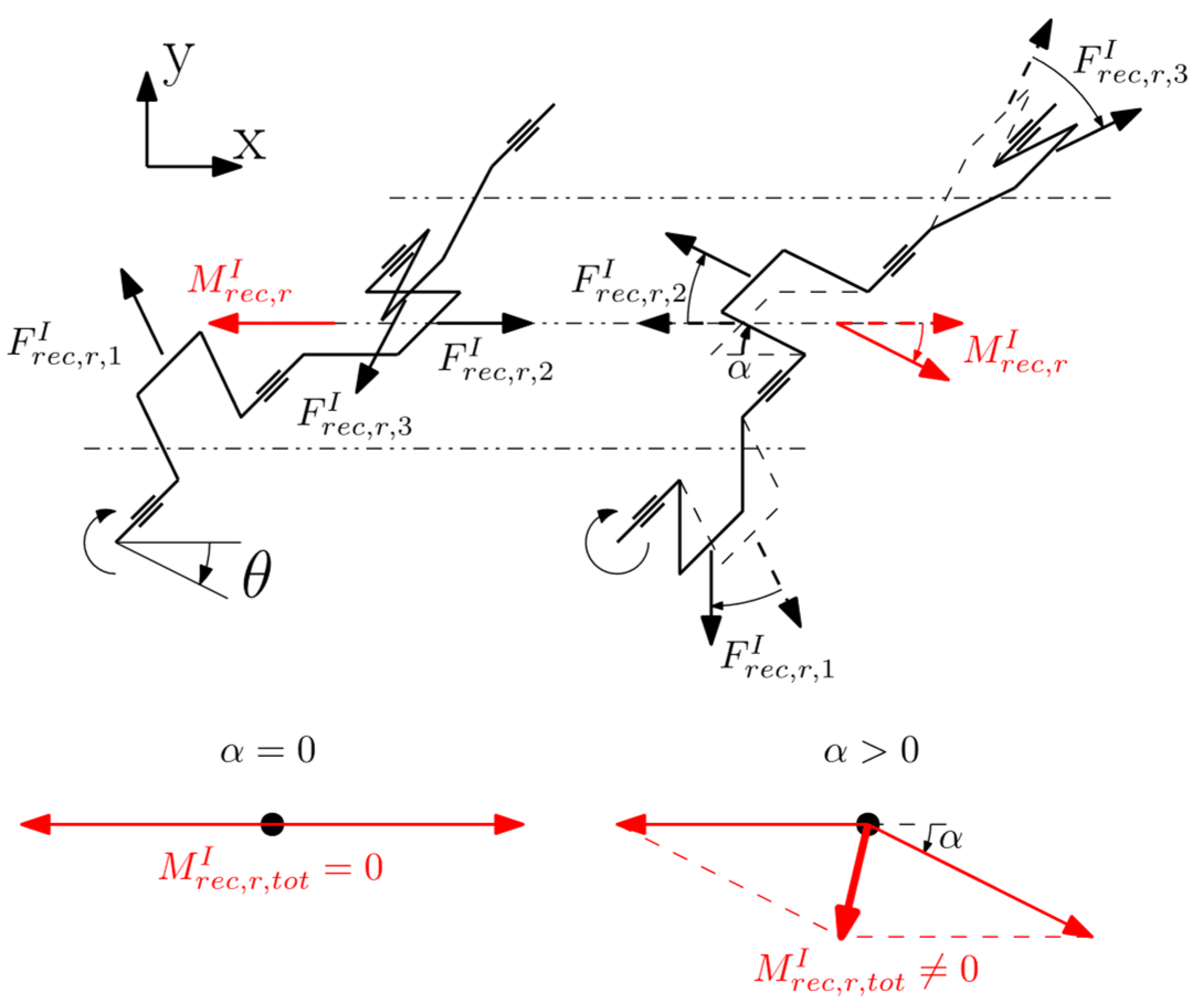
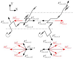
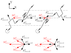
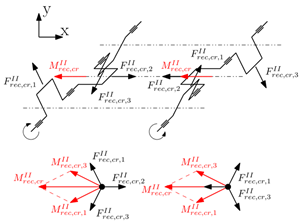
Although increasing the offset angle improves the scavenging process and enhances performance, it also introduces imbalance in the engine. This imbalance arises because the resulting forces and moments on each crankshaft become misaligned. Just as a preliminary example, consider only the rotating portion of the first-order reciprocating forces in the 3-cylinder co-rotating configuration, without offset. The two resultant moments are aligned in opposite directions, effectively canceling each other out. However, with a non-zero offset angle, a resultant moment arises in the θ + π α 2 direction. Figure 5 illustrates the direction of the resulting moment (red arrows), M r e c , r I , generated by the rotating portion of the first-order alternating forces of each crank mechanism (black arrows), F r e c , r , i I . When an offset is introduced, the vectors of the two shafts are no longer parallel, resulting in a residual moment M r e c , r , t o t I .
The analogous reasoning applies to the other components of the reciprocating forces and engine configurations. The greater the offset, the greater the imbalance. In this study, four offset values were considered: 0°, 5°, 10°, and 15°. These values were chosen because the fluid dynamic advantages in the scavenging process due to offset reach an optimum around 10–15°. Beyond this range, further increases are no longer beneficial [23]. To maintain a constant combustion chamber volume in the presence of an offset, the center distance between the two crankshafts has been reduced to bring the pistons closer together. Despite sharing a portion of the cylinder, the kinematics of the pistons prevent any collision between them.

3. Model Description

The analysis of the balancing of the OP engine has been conducted by developing an analytical model based on the mechanics of the slider-crank mechanism. The full derivation of crank mechanism dynamics is provided in numerous textbooks, for example [20] or [24]. The initial model does not account for the number of cylinders or the engine architecture but focuses on determining the loads of the individual slider-crank mechanism. The developed model enables the evaluation, for each angular position, of the forces due to moving masses and those arising from gas pressure, thereby obtaining the resulting forces at the crank supports and the output torque. The inertial forces were derived analytically by studying the kinematics of the crank mechanism, while the gas forces were obtained based on a pressure profile derived by preliminary thermo-fluid-dynamic calculations. Specifically, both analytical and empirical formulas were employed, and the operating cycle has been divided into different phases: intake/exhaust, compression, combustion, and expansion (in a two-stroke engine intake and exhaust phases are treated as a single phase). The intake/exhaust phase has been simply approximated using a constant pressure value equal to the intake/boost pressure. The compression and expansion phases were modeled considering generic polytropic transformations:
p θ V ( θ ) 1.35 = p s c V s c 1.35 ,
p θ V ( θ ) 1.25 = p s e V s e 1.25 ,
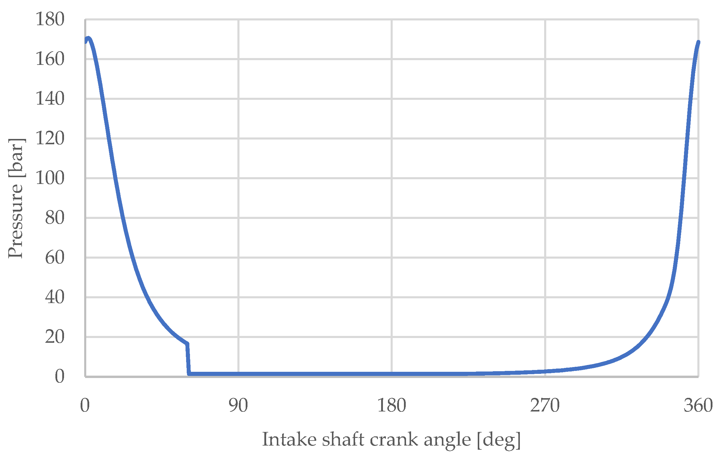
where the subscript s c refers to the pressure p and volume V at the beginning of compression phase, while the subscript s e refers to the pressure p and volume V at the beginning of expansion phase. Finally, the combustion phase has been modeled using the differential form of the first law of thermodynamics with the adoption of the Wiebe heat release model [20]. Figure 6 depicts the pressure profile considered.
By considering the offset angle between the two shafts, the number of cylinders, and the specific firing order, it has been possible to allocate these factors in space and time, thereby deriving the global action of the forces on the entire engine system and obtaining the complete model. However, when working with a design concept that significantly diverges from conventional approaches, it is essential to exercise caution in scenarios where standard assumptions may no longer hold. In a conventional single-piston engine, the volume change is straightforward, as it is simply calculated as the cylinder area multiplied by the piston stroke. However, in an OP design, the two pistons may move at different speeds and in opposite directions while sharing a single working volume and pressure. As a result, the pressure profile can no longer be directly correlated with the crank angle, as in conventional approaches, since the volume may vary due to the offset angle. Morton [25] analyzed this aspect in his article. He assumed the pressure profile to be constant with respect to the exhaust crankshaft, meaning that one piston always experiences the same pressure profile regardless of a possible offset between the two crankshafts, while only the intake one is affected by the offset. The authors of this paper believe that this approach could be potentially misleading and therefore adopt a different methodology, in which the pressure profile has been instead described as a function of the instantaneous volume within the cylinder, which varies according to the offset.
The pressure profile does not account for the fluid dynamic advantage of the offset in enhancing trapping efficiency. This simplification is intentional, as the primary objective of this study is to isolate and analyze the impact of crankshafts offset on the engine structural behavior. Incorporating the effects of increased trapping efficiency could distort the direct influence of the offset. To maintain a clear evaluation, the authors deliberately neglected this variable from the model.

3.1. Offset Modeling

The introduction of an offset angle not only affects the port timing but also causes a significant change in the kinematics of the overall system, while the kinematics of each single crank mechanism remain unaffected. In an OP engine, the variation of the cylinder volume depends on the instantaneous positions of both pistons. As a result, introducing an offset angle alters the volume swept by the pistons and, consequently, the engine’s effective displacement. To properly address this phenomenon, it is necessary to explain how this parameter has been modeled.
In a configuration without offset, both pistons reach the top dead center (TDC) simultaneously. In contrast, with an offset angle, when the exhaust piston reaches TDC, the intake piston has not completed its stroke yet. Similarly, when the intake piston reaches TDC, the exhaust piston has already begun its expansion stroke. As the offset value increases, the dead volume also grows. Consequently, in an OP engine with offset, the minimum cylinder volume no longer coincides with the simultaneous TDC of the two involved crank mechanisms as in the case of zero offset. It is reached at an angular distance of α / 2 from the TDC of one of the crankshafts, when the pistons are closest to each other. To handle this, a specific convention for the angular reference system was adopted in the model. In this study, the reference has been defined relative to the intake piston, with the crank angle θ = 0 ° corresponding to the TDC of cylinder 1 of the intake crankshaft, see Figure 5. As the offset varies, the position of the exhaust piston is updated accordingly, relative to the intake piston. For instance, with an offset of 10°, at a crank angle of θ = 0 ° , the intake piston is at TDC, while the exhaust piston is at the position it would occupy at 10 crank degrees relative to TDC. It is important to note that this convention is adopted solely to define a reference crankshaft for plotting the graphs. However, the pressure profile does not remain constant relative to this crankshaft; instead, it is updated based on the offset angle.
Another critical aspect influenced by the offset angle is the spark advance, which is typically defined as the angular distance (in crank degrees) before TDC, at which combustion begins. As previously mentioned, with an offset angle, the minimum cylinder volume no longer aligns with TDC. If ignition timing were fixed relative to the TDC of one crankshaft, the spark advance would vary as a function of the offset angle. This variability could lead to significant changes in combustion characteristics, as earlier spark advance tends to produce higher peak pressures and temperatures, which occur at earlier crank angles. To eliminate this dependency, the start of combustion was related to the point of minimum volume rather than TDC. This approach ensures that combustion timing remains independent of the offset angle, allowing for a more consistent and unambiguous comparison between different configurations.

3.2. Engine Parameters

The main engine parameters used in the model are reported in Table 2. They include geometric dimensions, masses, and operating conditions. These values do not refer to a specific engine but were chosen to encompass a wide range of engines, from passenger cars to high-performance applications.

4. Results

In this section, the results of the analysis are presented, structured as follows. First, the results related to the engine balancing were shown, divided into the two architectures introduced in Section 2: 3-cylinder, 4-cylinder. For each of these configurations, the analysis initially addresses the difference between co-rotating and counter-rotating crankshafts, highlighting the impact of the crankshaft geometry on the resultant moments and the overall system balance. Subsequently, the influence of the offset angle was examined, evaluating its implications in both co-rotating and counter-rotating configurations.
Finally, a brief analysis of the torque output as the offset angle varies was conducted to understand how this parameter affects not only the engine balancing but also the way the total torque output is split between the two crankshafts.

4.1. Engine Balancing

The resultant moment was calculated as a function of crank angle, providing the imbalance profile over a complete engine cycle. The magnitude of the imbalance was analyzed by decomposing it into the two components, x and y. Particularly, the x-component is parallel to the cylinder axes, while the y-component is perpendicular to the cylinder plane (Figure 1). This perspective allows not only to evaluate the magnitude of the resultant moment but also to understand how the direction of the resultant moments may influence the vehicle dynamic behavior.
For each architecture the following two scenarios were considered:
  • Maximum achievable local balance with counterweights (each crank throw is balanced with respect to the centrifugal forces and the rotating portion of the first-order reciprocating forces with the consequent balancing with respect to the corresponding moments). This choice is the one that minimize the load on main journal bearings, therefore is the best in term of bearing reliability.
  • Crank throws are balanced solely with respect to the centrifugal forces with the consequent balancing with respect to the corresponding moments (the rotating portion of the first-order reciprocating forces of each crank mechanism and the corresponding moments intentionally remain unbalanced). This choice is the one that maximize the possible interaction between the moments generated by the two crankshafts.

4.1.1. Difference Between Co-Rotating and Counter-Rotating Configurations

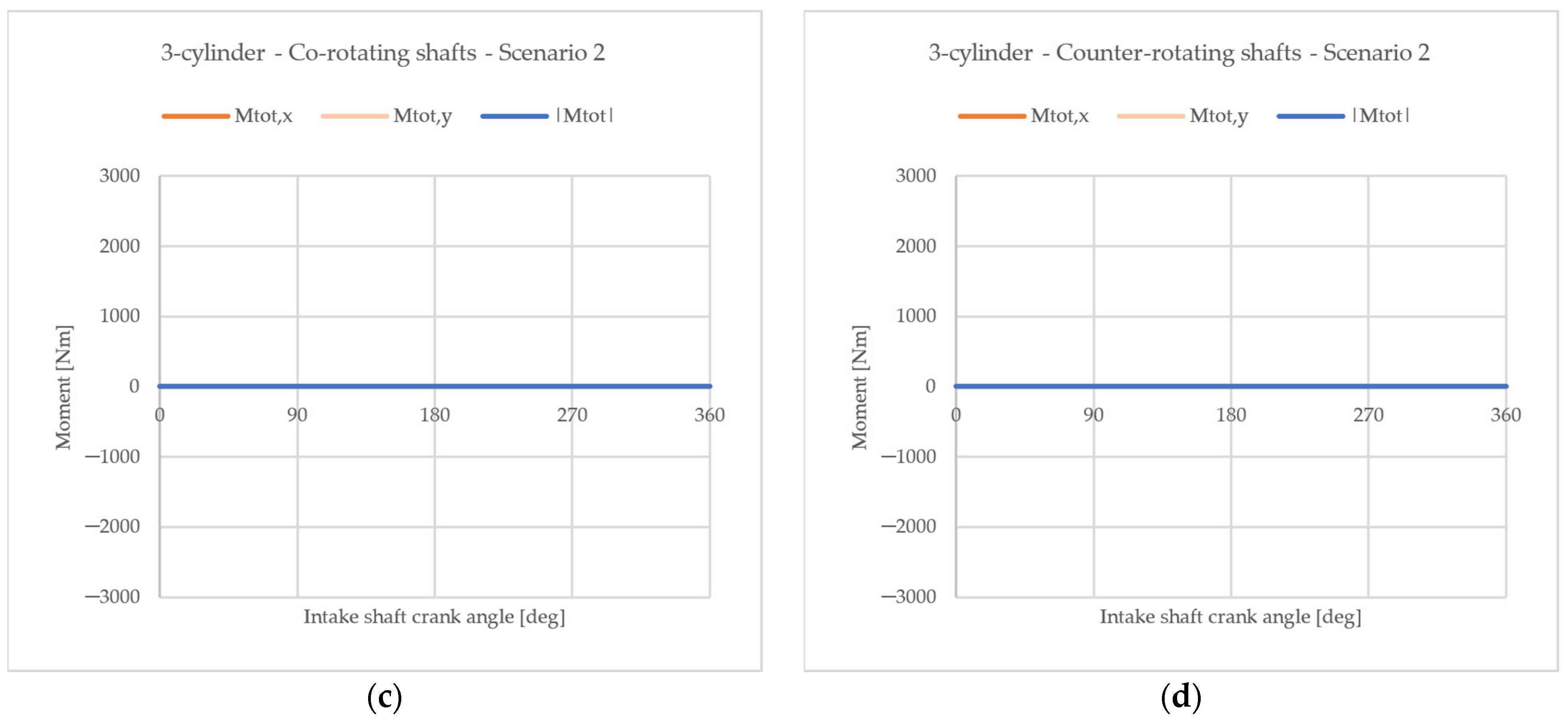
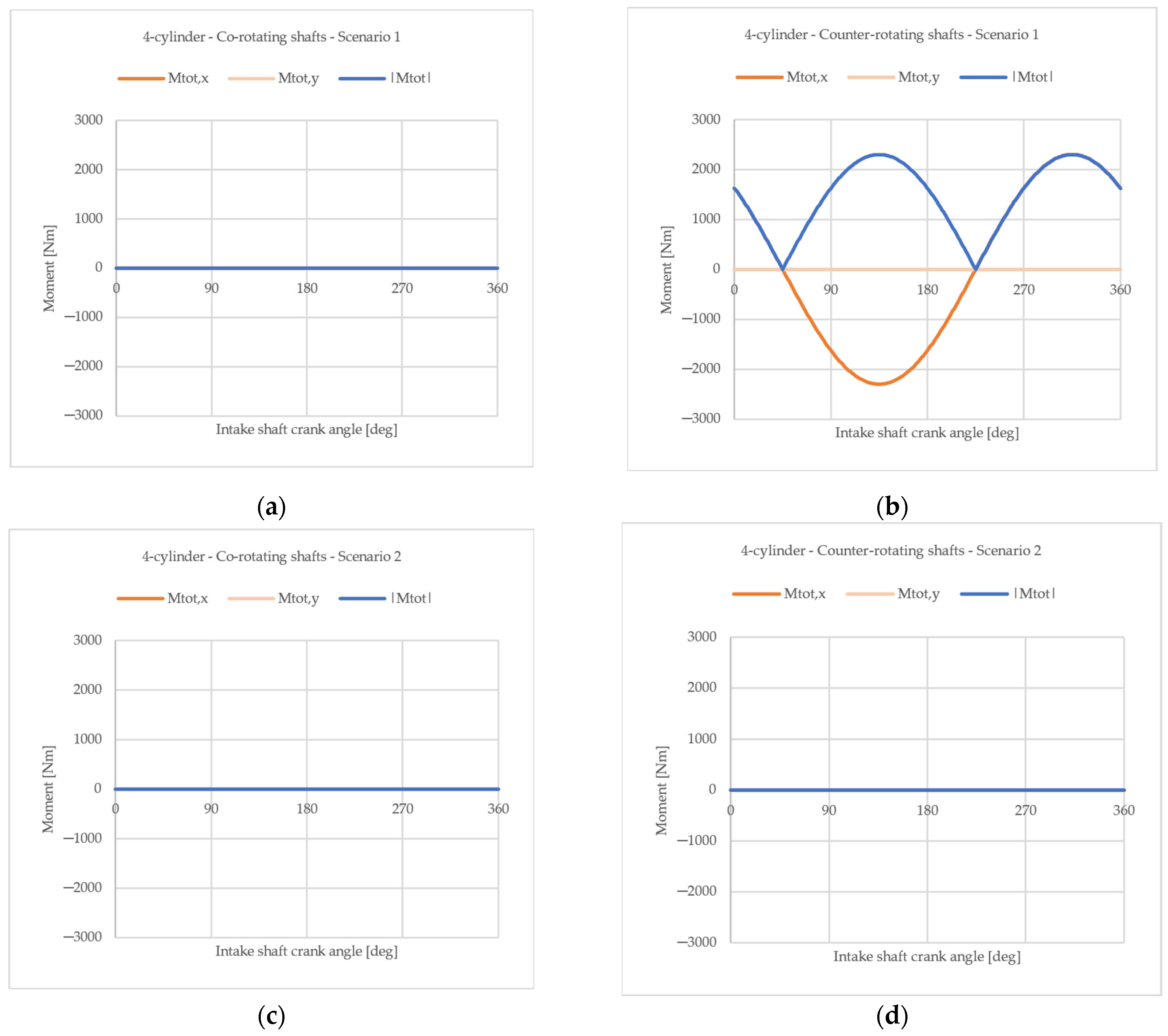
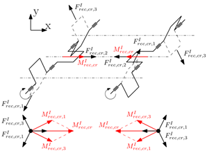
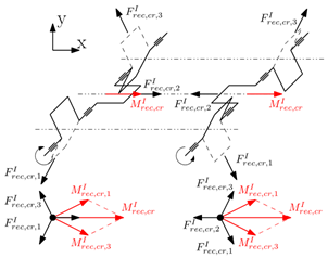
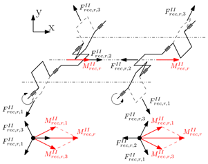
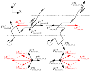
Before analyzing the effects of offset, it is crucial to consider the differences between co-rotating and counter-rotating shaft configurations. In the co-rotating shaft configuration, since the two shafts are identical and exhibit a phase difference of 180° between them, each moment component of one shaft is balanced by the corresponding component of the other shaft. Conversely, for counter-rotating shafts, where the two shafts are symmetric with respect to the plane orthogonal to the cylinder axes, the rotating component of the first shaft balances the counter-rotating component of the second shaft, and vice versa. Table 3 depicts the direction of forces and how the moments were evaluated. Only the 3-cylinder configuration is reported, as the derivation of the 4-cylinder one is straightforward.
Considering the two scenarios presented above, an important difference emerges between co-rotating and counter-rotating configurations.
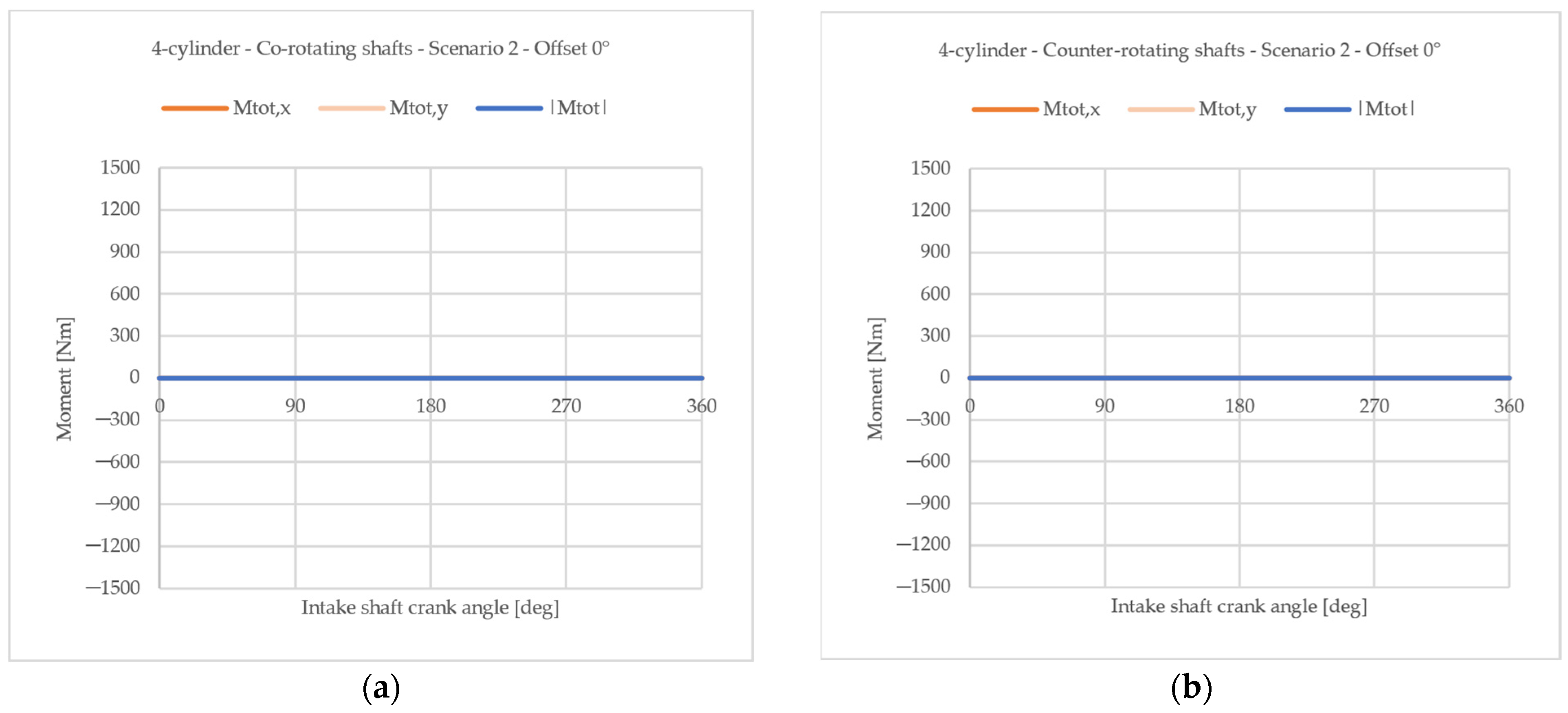
On one side, in the case of co-rotating shafts, the engine is perfectly balanced in both cases. In fact, if the moments generated by the rotating portion of the first-order reciprocating forces are left unbalanced (Scenario 2), they will be counteracted by the moments induced by the corresponding components from the other shaft. Therefore, in this configuration of co-rotating shafts, either balancing or not balancing the rotating component of the first-order moments generated by the reciprocating forces is a valid option. However, adopting co-rotating shafts with the first-order rotating forces balanced by counterweights on both shafts (Scenario 1) offers the advantage of reducing the load on the crankshaft journals and bearings, increasing their reliability.
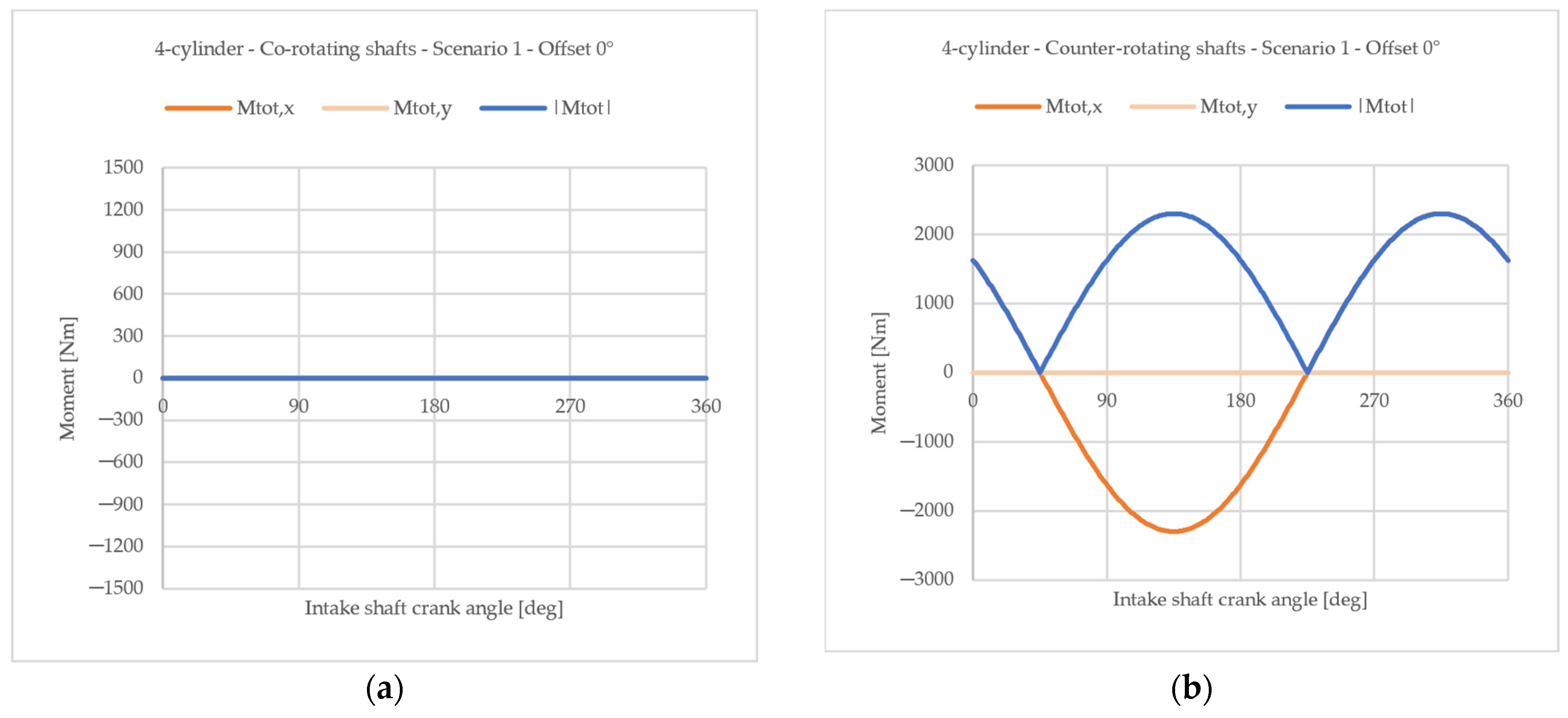
In contrast, for counter-rotating shafts, the two scenarios lead to entirely different balancing outcomes. Given that the moments generated by the rotating components of the first-order reciprocating forces of the two shafts rotate in opposite directions due to the counter-rotating configuration, they cannot cancel each other out. The same applies to the moments induced by the counter-rotating components of the first-order reciprocating forces. As a result, in Scenario 1, where the moments of the rotating component of the first-order reciprocating forces are balanced by counterweights, the counter-rotating counterparts remain unbalanced, generating a maximum imbalance moment. The only way to achieve a perfectly balanced engine in the counter-rotating configuration is to not balance the moments generated by the rotating components of the first-order reciprocating forces using counterweights (Scenario 2).
Figure 7 and Figure 8 present the resultant moment divided into x-component, y-component, and magnitude for 3-cylinder and 4-cylinder configurations, respectively.

4.1.2. Influence of an Offset Angle Between the Two Crankshafts

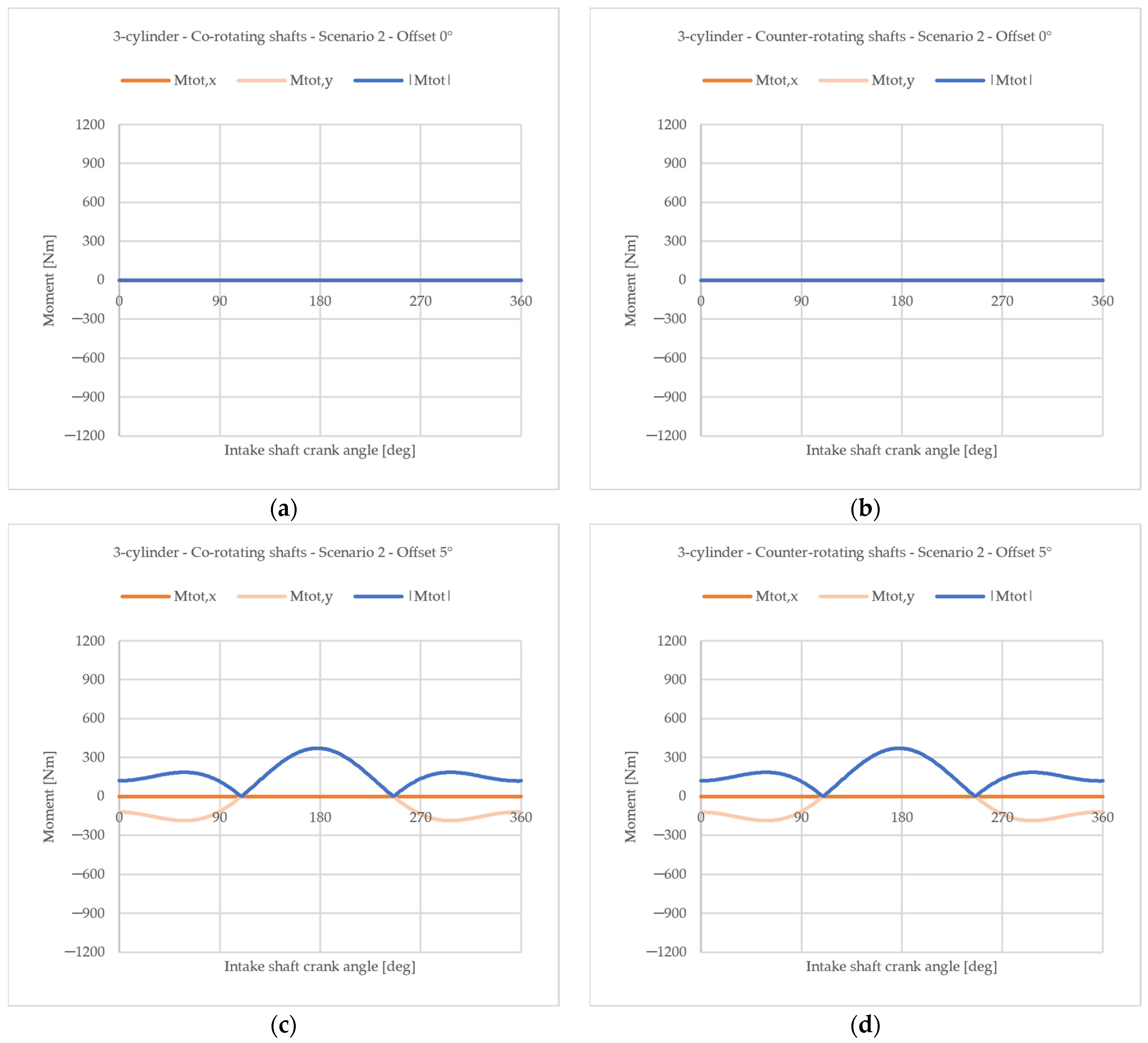
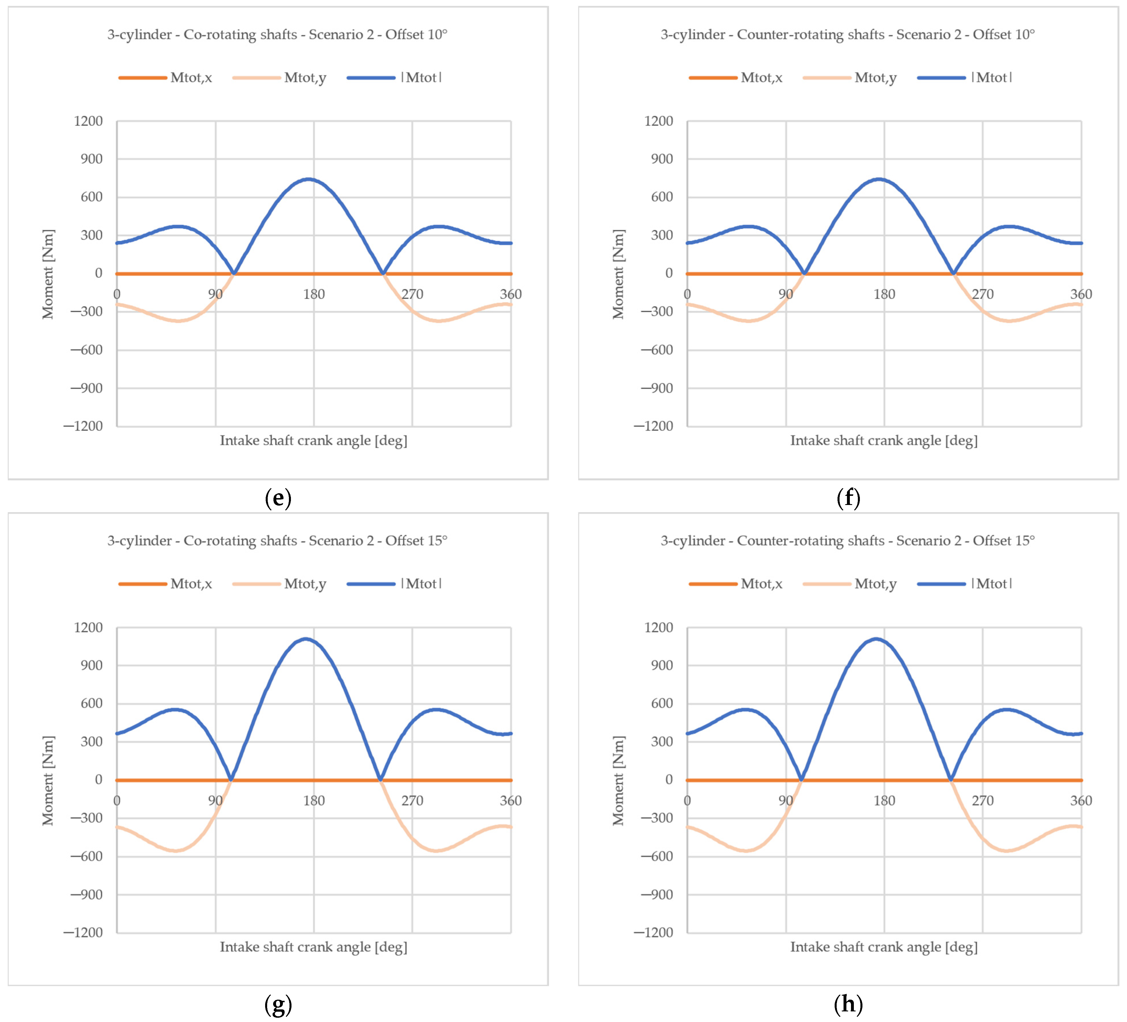
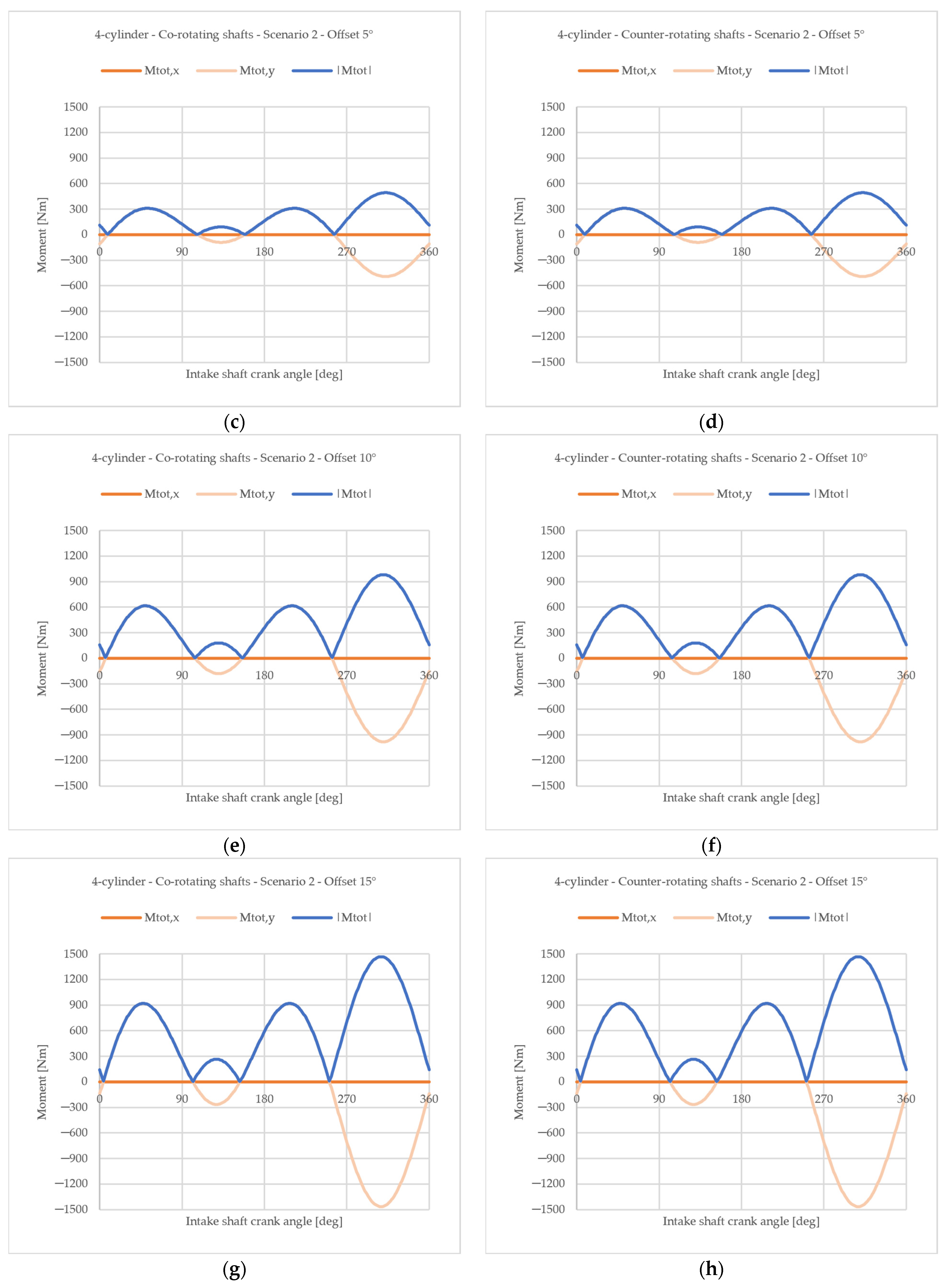
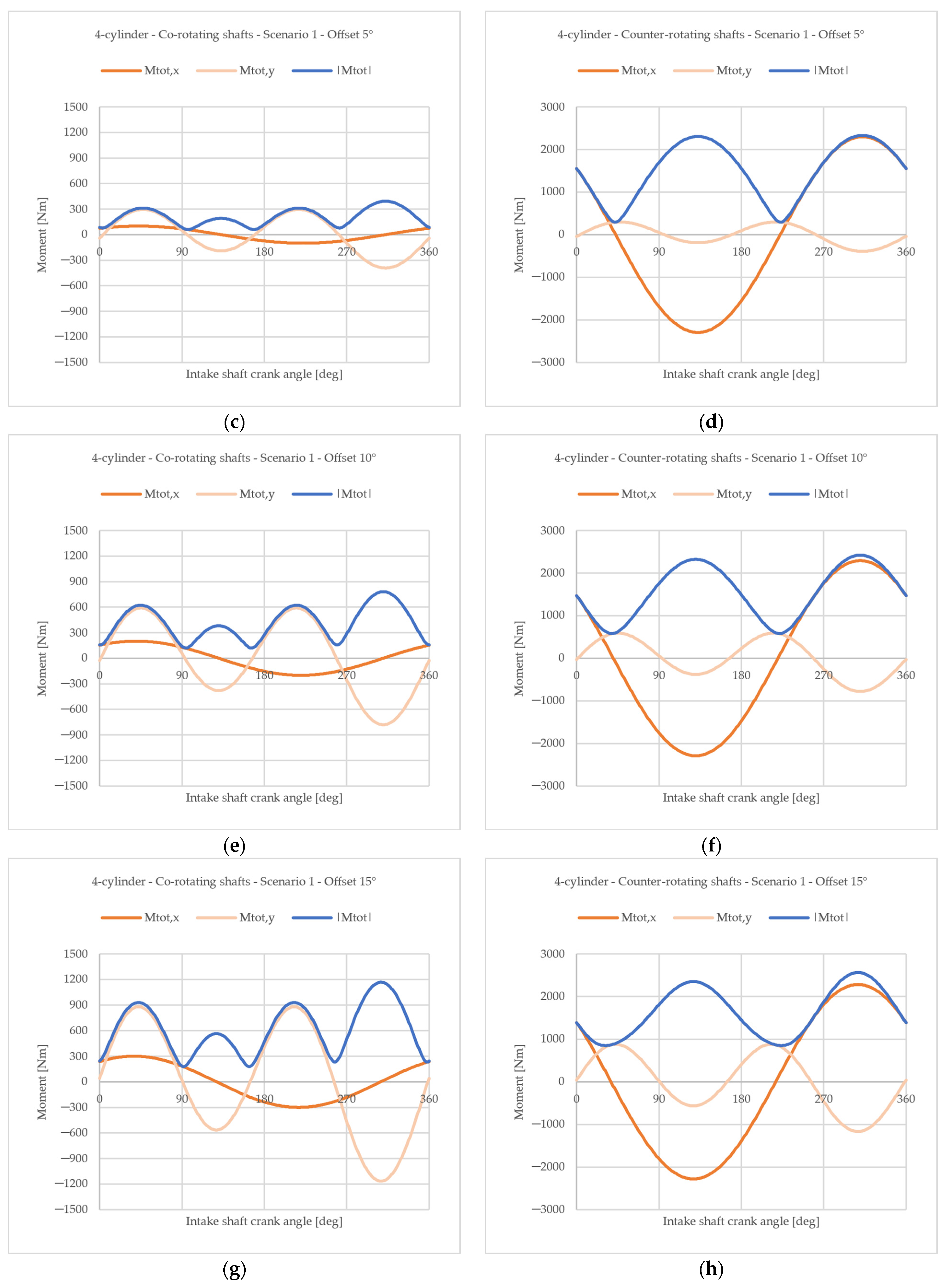
Introducing an offset angle causes both configurations to become unbalanced. However, they exhibit different behaviors depending on the specific scenario considered. In Scenario 2, where the rotating component of the first-order reciprocating forces remains unbalanced, both configurations exhibit the same behavior, as depicted in Figure 9 and Figure 10. The total moment is represented by a vector with a constant direction and a variable magnitude. This direction is aligned with the y-axis, which is orthogonal to the plane of the cylinder axes. Since the direction remains fixed, an advantage of this configuration (Scenario 2) is the ability to use engine mounts with different stiffness values in different directions. As these unbalanced moments are transmitted to the chassis through the engine mounts, understanding their behavior allows for improved mount design and reduced vibration transmission from the engine to the chassis. However, the orientation of the engine is critical. If the engine is mounted vertically, i.e., with the cylinder axes parallel to the vehicle vertical axis, the vibrations generated by the engine may be decoupled from those transmitted vertically from the ground. However, since the application considered in this contribution addresses an OP engine fueled by hydrogen, it would be more likely mounted horizontally to provide sufficient space for the hydrogen tank above it. In this case, the two vibration sources would have the same direction and could not be decoupled.
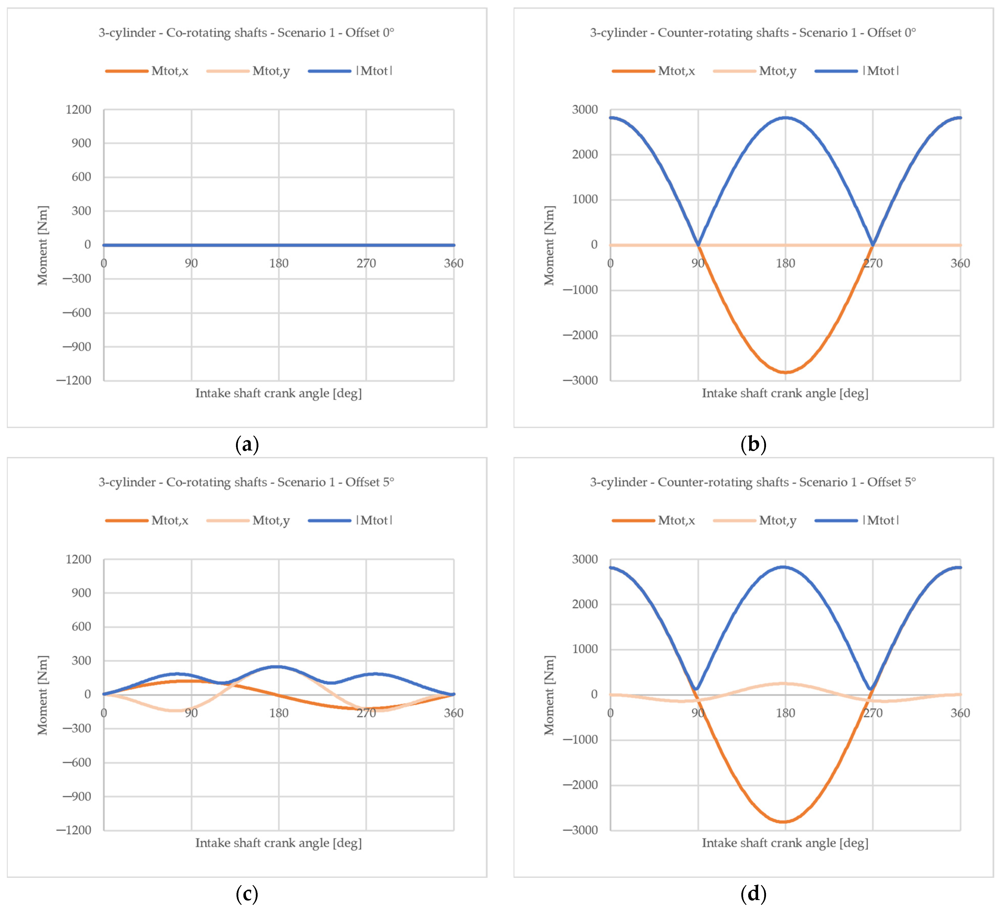
In Scenario 1 however, the two configurations exhibit completely different behaviors (Figure 11 and Figure 12). As mentioned earlier, the counter-rotating shafts’ configuration is already unbalanced without the offset and thus remains unbalanced with the offset introduction. In contrast, the co-rotating configuration presents the unbalanced moment as a rotating vector with a magnitude lower than the one of Scenario 2 addressed before, where the rotating component of the first-order reciprocating forces is not balanced by counterweights. In this case, the engine mounts must have the same stiffness in all directions, and the engine orientation no longer represents a decupling option.
In conclusion, for both engine architectures (3-cylinder and 4-cylinder), the co-rotating shaft configuration appears to be the most promising. It offers the flexibility to choose between a more conservative setup for bearing reliability (Scenario 1) or a configuration with a resultant moment of constant direction (Scenario 2). In contrast, the counter-rotating shaft configuration can only achieve overall balancing if the rotating component of the first-order reciprocating forces remains unbalanced for each crankshaft.
Reducing imbalances is the first step in minimizing vibrations transmitted to the chassis. These cyclic loads can lead to fatigue failure of the engine mounts, and the presence of an offset further increases these loads, exposing chassis components to higher stress.
Beyond the choice of co-rotating or counter-rotating shaft configurations and the offset angle, it is essential to emphasize that the imbalance is solely related to inertial forces, as gas forces naturally self-balance within the engine. Consequently, mass also plays a crucial role, and reducing it, whether through optimized component geometry or the use of high-performance materials, can help mitigate the negative effects of the offset.

4.2. Output Torque

As previously mentioned, the mechanical work produced by an OP engine is split between the two crankshafts due to the presence of two pistons sharing the same cylinder, and each collecting part of the energy produced by the combustion of gases, represented by the indicating work p d V . Moreover, when an offset is present, the two pistons do not move symmetrically, resulting in an unequal distribution of mechanical work between them. Defining expansion work as positive and compression work as negative, when the exhaust piston passes TDC and begins the expansion phase, the work collected by it becomes positive. Meanwhile, the intake piston has not reached TDC yet and remains in the compression stroke, meaning the work in this case is still negative [25].
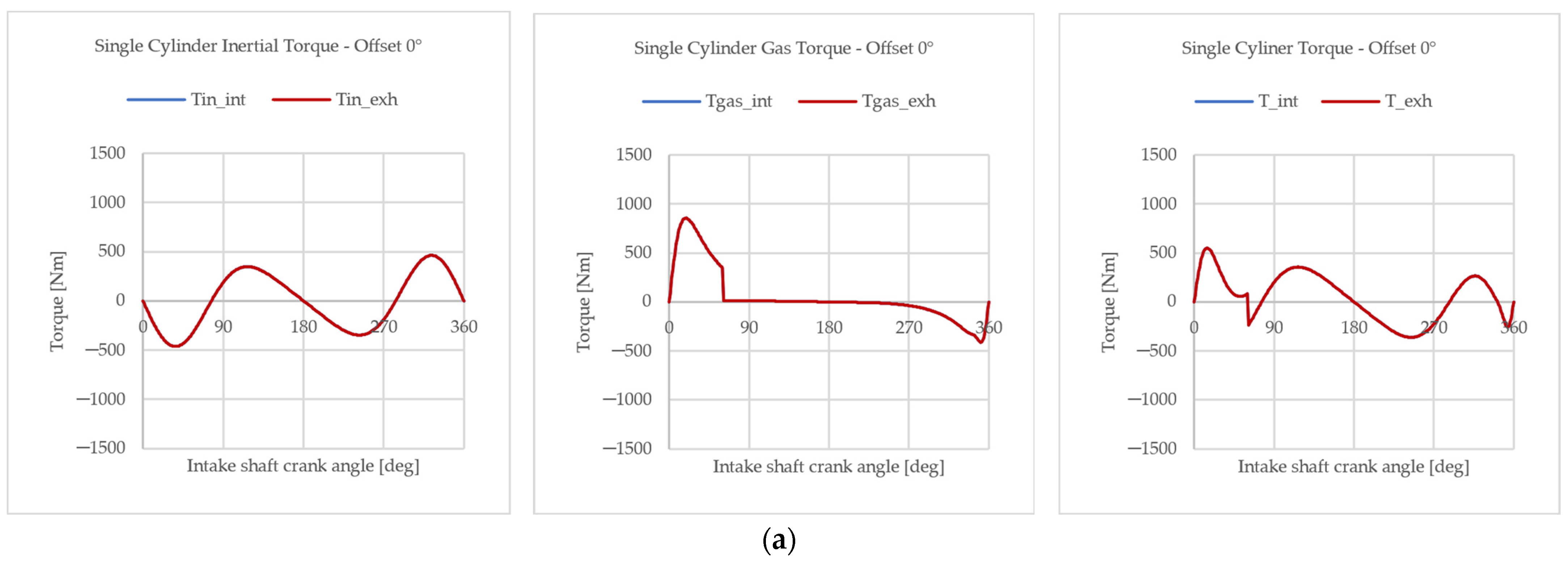
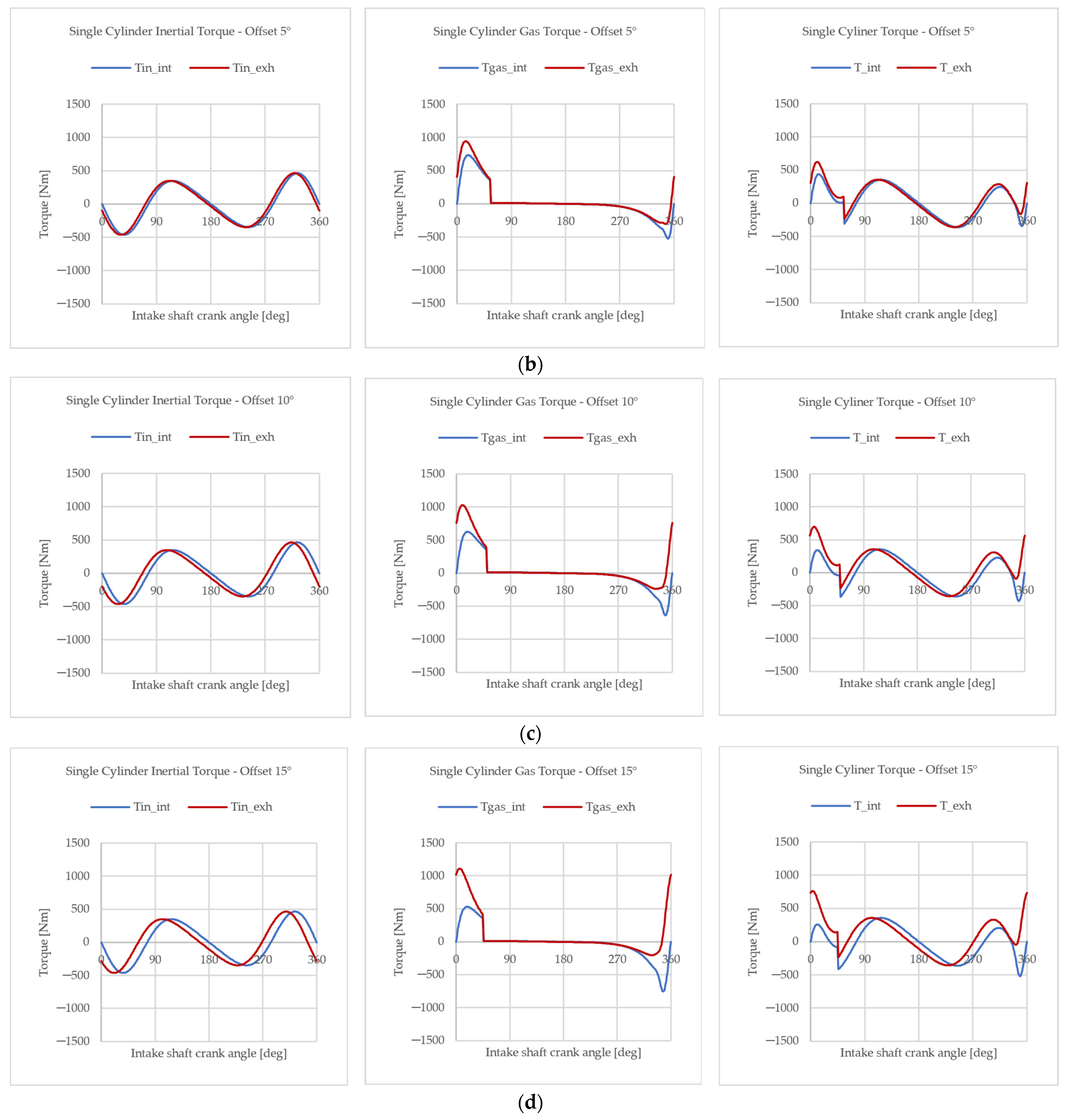
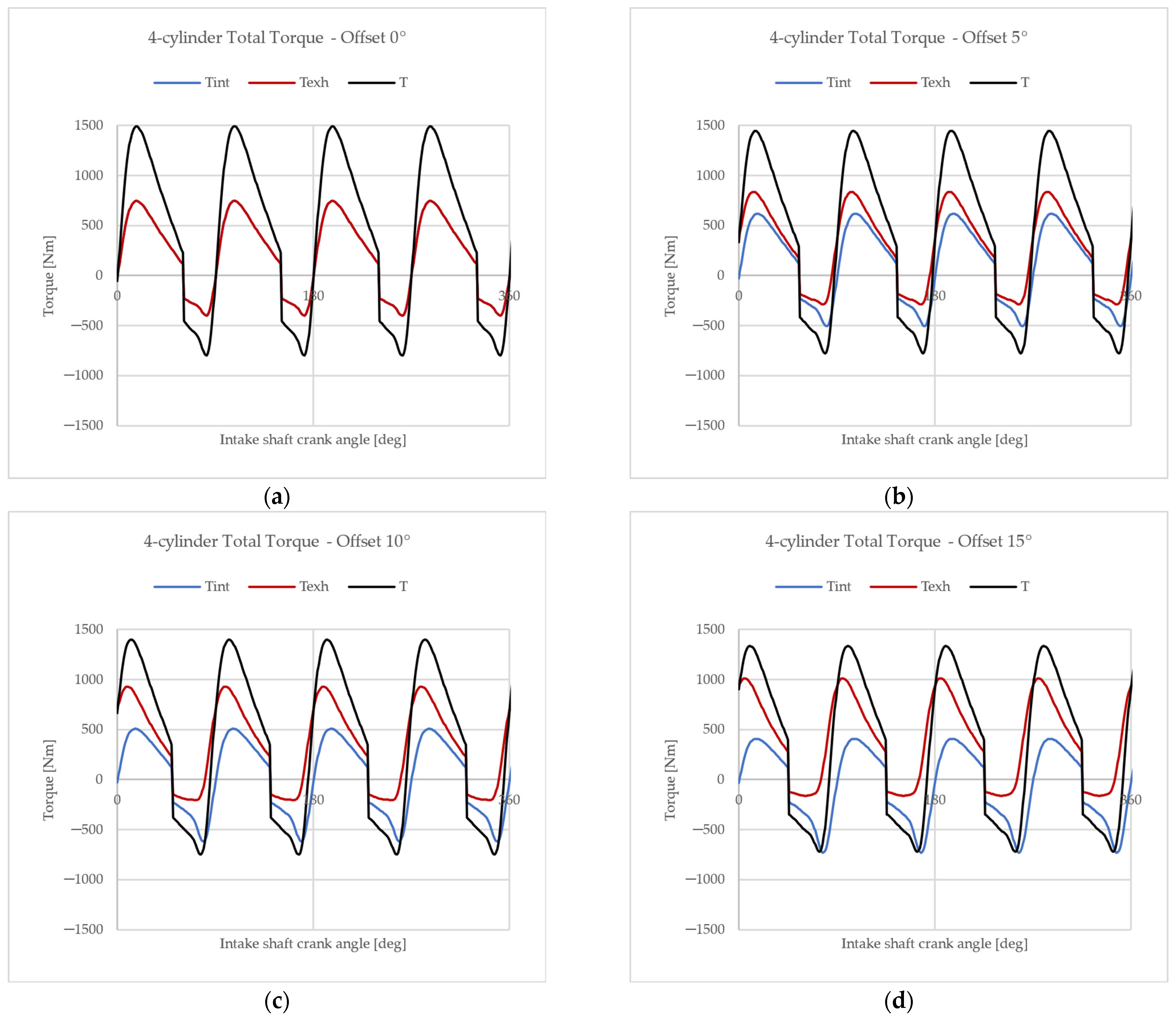
The output torque is therefore computed as the sum of the contributions from the two crank mechanisms, which are evaluated separately. Figure 13 illustrates the output torque profile generated by each crankshaft over a complete engine cycle for a single cylinder. It is evident that, increasing the offset angle, the exhaust piston operates in a more favorable position than the intake piston, allowing it to generate greater torque. However, the intake piston generates less torque than the zero offset configuration and in extreme cases, for high offset values, the intake shaft may perform zero or negative work over an engine cycle.
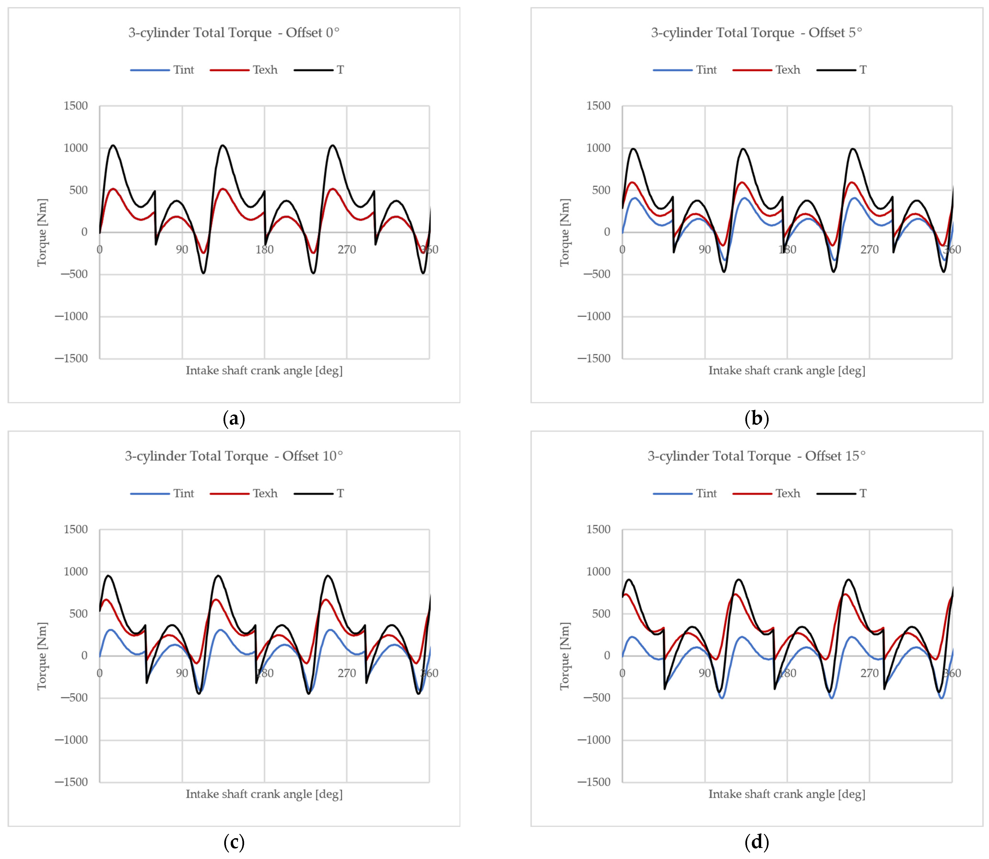
Figure 14 and Figure 15 illustrate the output torque of the whole OP engine, the 3-cylinder, and the 4-cylinder, respectively. Neglecting the variation in trapping efficiency, the introduction of an offset results in a reduction in the total engine torque output (Table 4). This reduction is primarily due to the delayed intake shaft timing, the decrease in the effective compression ratio, and the earlier opening of the exhaust ports caused by the advanced timing of the exhaust piston. However, considering the improvement of the trapping efficiency related to the introduction of the offset and neglected in this contribution, the negative effects recorded here would be compensated and the output torque would be higher than in the case without offset [23]. Moreover, from a structural perspective, introducing the offset will result in a higher load on the exhaust piston and the exhaust-side portion of the liner due to the increased thrust force.
Although it would be interesting to compare the presented results with engines designed for the same road applications, the purpose of this study is to quantify the differences that emerge between the torques output from the two crankshafts as a function of the offset rather than analyze the absolute value of the total torque output.

5. Conclusions

This paper presented an analytical methodology for evaluating the balance of two-stroke OP engines. The proposed approach took four key design parameters into account: two that also influence the balancing of conventional four-stroke reciprocating engines (inline, V, and boxer configurations), which are the number of cylinders and the angle between the crank throws, and two parameters specific to OP engines, which are the rotational direction of the two crankshafts (co-rotating and counter-rotating) and the offset angle. The offset angle was also analyzed concerning its effect on the engine output torque.
An analytical model was developed to assess the resulting imbalance moment and its variation over a full engine cycle. This model was then applied to investigate two configurations: a 3-cylinder and a 4-cylinder OP engine. For both configurations, co-rotating and counter-rotating crankshafts were examined under four offset angle conditions: 0°, 5°, 10°, and 15°. Two different balancing scenarios were considered: one in which the rotating component of first-order reciprocating forces was fully balanced by counterweights in each individual crankshaft, and another in which this component was left unbalanced.
The results provided valuable insights. Counter-rotating crankshafts could not reach a global balancing when the rotating component of first-order reciprocating forces were balanced with counterweights, as the counter-rotating counterpart remained entirely unbalanced. Conversely, co-rotating crankshafts could be utilized in both scenarios. However, leaving the rotating component of first-order reciprocating forces locally unbalanced increased the loads on the main bearings, potentially leading to higher wear.
Introducing an offset angle resulted in increased imbalance in both configurations. Nevertheless, the co-rotating shafts configuration emerged as the preferable choice, as it led to a lower overall imbalance and offered greater design flexibility.
Finally, the impact of the offset angle on engine output torque was also analyzed. The offset causes an uneven torque distribution between the two crankshafts. Specifically, the exhaust-side crankshaft is positioned more favorably, generating higher torque, while the intake-side crankshaft produces lower torque, and in extreme cases, even zero mean torque.
In conclusion, the proposed methodology represents a powerful tool in the early stages of OP engine design. Thanks to a spreadsheet-based model, this approach enables the rapid, effective, and straightforward generation of key design guidelines, reducing the time and complexity typically associated with early-stage development. The model does not account for dynamic effects; therefore, for a more detailed analysis, particularly in the final design stages, more comprehensive and complex dynamic models (such as using FEA or multibody analysis) could be employed. In addition, from a fluid dynamics point of view, more studies must be conducted to consider the transient characteristics of hydrogen combustion and evaluate a more precise pressure profile. The proposed model is not intended to serve as a standalone design tool but rather as a support in the preliminary design phases, where more advanced methods may be unnecessarily complex or computationally demanding.

Author Contributions

Conceptualization, A.P. and S.G.B.; methodology, A.P. and S.G.B.; software, A.P.; validation, A.P. and S.G.B.; formal analysis, A.P.; investigation, A.P., S.G.B. and V.M.; resources, A.P. and S.G.B.; data curation, A.P.; writing—original draft preparation, A.P.; writing—review and editing, S.G.B., V.M. and M.G.; visualization, A.P. and S.G.B.; supervision, M.G.; project administration, M.G.; funding acquisition, M.G. All authors have read and agreed to the published version of the manuscript.

Funding

This research was financed by European Union-Next generation EU trough the “Piano Nazionale Di Ripresa E Resilienza (Pnrr)–Missione 4 Componente 2, “Dalla Ricerca All’impresa” Investimento 1.4, (CN00000023). In the context of the “Sustainable Mobility Center (Centro Nazionale per la Mobilità Sostenibile—CNMS)”—Spoke 12—Avviso MUR 3138/2021 modificato con DD 3175/2021.

Institutional Review Board Statement

Not applicable.

Informed Consent Statement

Not applicable.

Data Availability Statement

The raw data supporting the conclusions of this article will be made available by the authors upon request.

Conflicts of Interest

The authors declare no conflicts of interest.

Nomenclature

SymbolsDefinition
α Offset angle
β Angle between crank throws
θ Crank angle
θ c y c l e Engine cycle duration
λ Conrod ratio
ω Engine speed
F Force
F r o t Centrifugal forces
F r e c Reciprocating forces
F r e c , r I Rotating component of first-order reciprocating forces
F r e c , c r I Counter-rotating component of first-order reciprocating forces
F r e c , r I I Rotating component of second-order reciprocating forces
F r e c , c r I I Counter-rotating component of second-order reciprocating forces
l c Conrod length
m c , r o t Conrod rotating mass
m c p Crank pin mass
m c w Crank web mass
m r e c Total reciprocating masses
M Moment
M r e c , r I Moment generated by rotating component of first-order reciprocating forces
M r e c , c r I Moment generated by counter-rotating component of first-order reciprocating forces
M r e c , r I I Moment generated by rotating component of second-order reciprocating forces
M r e c , c r I I Moment generated by counter-rotating component of second-order reciprocating forces
N Number of cylinders
n c m Number of crank mechanisms
p Gas pressure
p s c Gas pressure at start of compression stroke
p s e Gas pressure at start of expansion stroke
r Crank radius
r c w Counterweights radius
V Volume
V s c Volume at start of compression stroke
V s e Volume at start of expansion stroke

References

  1. Estevez, R.; Aguado-Deblas, L.; López-Tenllado, F.J.; Bautista, F.M.; Romero, A.A.; Luna, D. Internal Combustion Engines and Carbon-Neutral Fuels: A Perspective on Emission Neutrality in the European Union. Energies 2024, 17, 1172. [Google Scholar] [CrossRef]
  2. Bao, J.; Wang, H.; Wang, R.; Wang, Q.; Di, L.; Shi, C. Comparative Experimental Study on Macroscopic Spray Characteristics of Various Oxygenated Diesel Fuels. Energy Sci. Eng. 2023, 11, 1579–1588. [Google Scholar] [CrossRef]
  3. Shi, C.; Cheng, T.; Yang, X.; Zhang, Z.; Duan, R.; Li, X. Implementation of Various Injection Rate Shapes in an Ammonia/Diesel Dual-Fuel Engine with Special Emphasis on Combustion and Emissions Characteristics. Energy 2024, 304, 132035. [Google Scholar] [CrossRef]
  4. Piergiacomi, A.; Barbieri, S.G.; Renso, F.; Mangeruga, V.; Giacopini, M. Investigation via Finite Element Analysis of the Influence of Boiling on the Thermo-Structural Behavior of the Engine. In SAE Technical Papers; SAE International: Warrendale, PA, USA, 2023. [Google Scholar] [CrossRef]
  5. Serrano, J.R.; Novella, R.; Piqueras, P. Why the Development of Internal Combustion Engines Is Still Necessary to Fight against Global Climate Change from the Perspective of Transportation. Appl. Sci. 2019, 9, 4597. [Google Scholar] [CrossRef]
  6. Martins, J.; Brito, F.P. Alternative Fuels for Internal Combustion Engines. Energies 2020, 13, 4086. [Google Scholar] [CrossRef]
  7. Volza, A.; Scrignoli, F.; Caprioli, S.; Mattarelli, E.; Rinaldini, C.A. Exploring the Potential of Hydrogen Opposed Piston Engines for Single-Cylinder Electric Generators: A Computational Study. In SAE Technical Papers; SAE International: Warrendale, PA, USA, 2023. [Google Scholar] [CrossRef]
  8. Verhelst, S.; Wallner, T. Hydrogen-Fueled Internal Combustion Engines. Prog. Energy Combust. Sci. 2009, 35, 490–527. [Google Scholar] [CrossRef]
  9. Shi, C.; Lei, J.; Tian, G.; Ma, Z.; Yang, X.; Zhu, J. Numerical Investigation on Recess Geometry Amelioration of an Ammonia-Hydrogen Zero-Carbon Wankel Engine. Renew. Energy 2025, 242, 122497. [Google Scholar] [CrossRef]
  10. Pirault, J.-P.; Flint, M. Opposed Piston Engines: Evolution, Use, and Future Applications; SAE International: Warrendale, PA, USA, 2010; ISBN 978-0-7680-1800-4. [Google Scholar]
  11. Mattarelli, E.; Cantore, G.; Alberto, C. Advances in The Design of Two-Stroke, High Speed, Compression Ignition Engines. In Advances in Internal Combustion Engines and Fuel Technologies; InTech: London, UK, 2013. [Google Scholar] [CrossRef]
  12. Herold, R.E.; Wahl, M.H.; Regner, G.; Lemke, J.U.; Foster, D.E. Thermodynamic Benefits of Opposed-Piston Two-Stroke Engines. In SAE Technical Papers; SAE International: Warrendale, PA, USA, 2011. [Google Scholar] [CrossRef]
  13. Mattarelli, E.; Caprioli, S.; Savioli, T.; Volza, A.; Di Gaetano Iftene, C.M.; Rinaldini, C.A. Virtual Development of a Single-Cylinder Hydrogen Opposed Piston Engine. Energies 2024, 17, 5262. [Google Scholar] [CrossRef]
  14. Lee, H.; Lee, M.-J. Recent Advances in Ammonia Combustion Technology in Thermal Power Generation System for Carbon Emission Reduction. Energies 2021, 14, 5604. [Google Scholar] [CrossRef]
  15. Ma, F.; Guo, L.; Li, Z.; Zeng, X.; Zheng, Z.; Li, W.; Zhao, F.; Yu, W. A Review of Current Advances in Ammonia Combustion from the Fundamentals to Applications in Internal Combustion Engines. Energies 2023, 16, 6304. [Google Scholar] [CrossRef]
  16. Sharma, V.; Panesar, A.; de Sercey, G.; Begg, S. A Review of Ammonia Combustion and Emissions Characteristics in Spark-Ignition Engines and Future Road Map. Energies 2024, 18, 41. [Google Scholar] [CrossRef]
  17. Heifetz, M.; Marsh, M. Engine Dynamics and Balancing. In SAE Technical Papers; SAE International: Warrendale, PA, USA, 1984. [Google Scholar] [CrossRef]
  18. Dagna, A.; Delprete, C.; Gastaldi, C. A General Framework for Crankshaft Balancing and Counterweight Design. Appl. Sci. 2021, 11, 8997. [Google Scholar] [CrossRef]
  19. Changming, H.; Sichuan, X. The Investigation of Self-Balanced Property and Vibration on the Particular Crankshaft System for an Opposed Piston Engine. In SAE Technical Papers; SAE International: Warrendale, PA, USA, 2016. [Google Scholar] [CrossRef]
  20. Ferrari, G. Internal Combustion Engines; Societa Editrice Esculapio: Bologna, Italy, 2014; ISBN 9788874887651. [Google Scholar]
  21. Hoag, K.; Dondlinger, B. Vehicular Engine Design; Powertrain; Springer: Vienna, Austria, 2016; ISBN 978-3-7091-1858-0. [Google Scholar]
  22. Basshuysen, V. Fred Schäfer Internal Combustion Engine Handbook: Basics, Components, Systems, and Perspectives; SAE International: Warrendale, PA, USA, 2016; ISBN 978-0-7680-8024-7. [Google Scholar]
  23. Mattarelli, E.; Rinaldini, C.; Savioli, T.; Cantore, G.; Warey, A.; Potter, M.; Gopalakrishnan, V.; Balestrino, S. Scavenge Ports Optimization of a 2-Stroke Opposed Piston Diesel Engine. In SAE Technical Papers; SAE International: Warrendale, PA, USA, 2017; Volume 2017. [Google Scholar] [CrossRef]
  24. Taylor, C.F. Internal Combustion Engine in Theory and Practice; The MIT Press: Cambridge, MA, USA, 1985; ISBN 9780262311021. [Google Scholar]
  25. Morton, R.; Riviere, R.; Geyer, S. Understanding Limits to the Mechanical Efficiency of Opposed Piston Engines. In SAE Technical Papers; SAE International: Warrendale, PA, USA, 2017; Volume 2017. [Google Scholar]
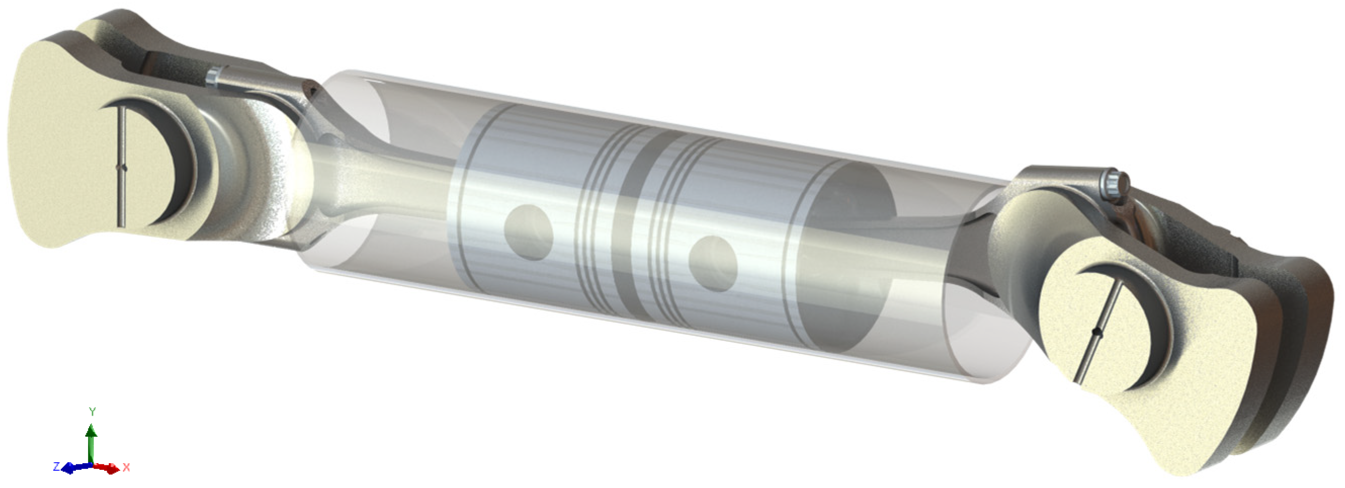
Figure 1. 3D model of a generic OP crank mechanism.
Applsci 15 02537 g001
Figure 2. Configurations considered in the analysis; (a) 3-cylinder crankshaft with β = 120 ° ; (b) 4-cylinder crankshaft with β = 90 ° .
Applsci 15 02537 g002
Figure 3. Crankshaft layouts of all configurations; (a) 3-cylinder co-rotating crankshafts; (b) 3-cylinder counter-rotating crankshafts; (c) 4-cylinder co-rotating crankshafts; (d) 4-cylinder counter-rotating crankshafts.
Applsci 15 02537 g003
Figure 4. Offset angle, α, between intake (left) and exhaust (right) crankshafts; (a) co-rotating shafts; (b) counter-rotating shafts.
Applsci 15 02537 g004
Figure 5. The resultant moment M r e c , r , t o t I generated by the rotating portion of the first-order alternating forces F r e c , r , i I of each crank mechanism in the 3-cylinder co-rotating configuration, with and without offset.
Applsci 15 02537 g005
Figure 6. Pressure profile.
Applsci 15 02537 g006
Figure 7. Resultant moment under zero offset conditions for 3-cylinder configuration; (a) co-rotating shafts with M r e c , r balanced; (b) counter-rotating shafts with M r e c , r balanced; (c) co-rotating shafts with M r e c , r unbalanced; (d) counter-rotating shafts with M r e c , r unbalanced.
Applsci 15 02537 g007aApplsci 15 02537 g007b
Figure 8. Resultant moment under zero offset conditions for 4-cylinder configuration; (a) co-rotating shafts with M r e c , r balanced; (b) counter-rotating shafts with M r e c , r balanced; (c) co-rotating shafts with M r e c , r unbalanced; (d) counter-rotating shafts with M r e c , r unbalanced.
Applsci 15 02537 g008
Figure 9. Resultant moment of co-rotating and counter-rotating shafts with M r e c , r unbalanced (scenario 2) and with different offset angles for 3-cylinder configuration; (a) co-rotating with 0° offset; (b) counter-rotating with 0° offset; (c) co-rotating with 5° offset; (d) counter-rotating with 5° offset; (e) co-rotating with 10° offset; (f) counter-rotating with 10° offset; (g) co-rotating with 15° offset; (h) counter-rotating with 15° offset.
Applsci 15 02537 g009aApplsci 15 02537 g009b
Figure 10. Resultant moment of co-rotating and counter-rotating shafts with M r e c , r unbalanced (scenario 2) and with different offset angles for 4-cylinder configuration; (a) co-rotating with 0° offset; (b) counter-rotating with 0° offset; (c) co-rotating with 5° offset; (d) counter-rotating with 5° offset; (e) co-rotating with 10° offset; (f) counter-rotating with 10° offset; (g) co-rotating with 15° offset; (h) counter-rotating with 15° offset.
Applsci 15 02537 g010aApplsci 15 02537 g010b
Figure 11. Resultant moment of co-rotating and counter-rotating shafts with M r e c , r balanced (scenario 2) and with different offset angles for 3-cylinder configuration; (a) co-rotating with 0° offset; (b) counter-rotating with 0° offset; (c) co-rotating with 5° offset; (d) counter-rotating with 5° offset; (e) co-rotating with 10° offset; (f) counter-rotating with 10° offset; (g) co-rotating with 15° offset; (h) counter-rotating with 15° offset.
Applsci 15 02537 g011aApplsci 15 02537 g011b
Figure 12. Resultant moment of co-rotating and counter-rotating shafts with M r e c , r balanced (scenario 2) and with different offset angles for 4-cylinder configuration; (a) co-rotating with 0° offset; (b) counter-rotating with 0° offset; (c) co-rotating with 5° offset; (d) counter-rotating with 5° offset; (e) co-rotating with 10° offset; (f) counter-rotating with 10° offset; (g) co-rotating with 15° offset; (h) counter-rotating with 15° offset.
Applsci 15 02537 g012aApplsci 15 02537 g012b
Figure 13. Output torque of a single cylinder; (a) 0° offset; (b) 5° offset; (c) 10° offset; (d) 15° offset.
Applsci 15 02537 g013aApplsci 15 02537 g013b
Figure 14. Output torque profile of a 3-cylinder OP engine as the offset angle varies: (a) 0° offset; (b) 5° offset; (c) 10° offset; (d) 15° offset.
Applsci 15 02537 g014
Figure 15. Output torque profile of a 4-cylinder OP engine as the offset angle varies: (a) 0° offset; (b) 5° offset; (c) 10° offset; (d) 15° offset.
Applsci 15 02537 g015
Table 1. Resultant forces and moments for the 3-cylinder and 4-cylinder crankshafts.
3-cylinder β = 120 ° Applsci 15 02537 i001 F r e c , r I = F r e c , r , i I 0 M r e c , r I = M r e c , r , i I 3 2 m r e c ω 2 r I c y l
F r e c , c r I = F r e c , c r , i I 0 M r e c , c r I = M r e c , c r , i I 3 2 m r e c ω 2 r I c y l
F r e c , r I I = F r e c , r , i I I 0 M r e c , r I I = M r e c , r , i I I 3 2 m r e c ω 2 r λ I c y l
F r e c , c r I I = F r e c , c r , i I I 0 M r e c , c r I I = M r e c , c r , i I I 3 2 m r e c ω 2 r λ I c y l
4-cylinder β = 90 ° Applsci 15 02537 i002 F r e c , r I = F r e c , r , i I 0 M r e c , r I = M r e c , r , i I 2 m r e c ω 2 r I c y l
F r e c , c r I = F r e c , c r , i I 0 M r e c , c r I = M r e c , c r , i I 2 m r e c ω 2 r I c y l
F r e c , r I I = F r e c , r , i I I 0 M r e c , r I I = M r e c , r , i I I 4 m r e c ω 2 r λ I c y l
F r e c , c r I I = F r e c , c r , i I I 0 M r e c , c r I I = M r e c , c r , i I I 4 m r e c ω 2 r λ I c y l
Table 2. Engine parameters.
Engine Main Parameters
Engine maximum speed6000 rpm
Bore80 mm
Stroke90 mm
Single cylinder displacement 900 cm3
Total displacement3-cylinder
4-cylinder
2700 cm3
3600 cm3
Conrod length ( l c ) 175 mm
Conrod ratio ( λ ) 0.257
Cylinder center distance100 mm
Masses
Assembled conrod665 g
Sliding bearing13.5 g
Conrod rotating mass ( m c , r o t ) 469 g
Conrod reciprocating mass209.5 g
Piston550 g
Piston pin137.50 g
Total piston rings18.50 g
Total reciprocating masses ( m r e c ) 915.5 g
Crankpin   ( m c p ) 330 g
Table 3. Direction of resultant moments for 3-cylinder configurations.
Co-Rotating ShaftsCounter-Rotating Shafts
M r e c , r I Applsci 15 02537 i003Applsci 15 02537 i004
M r e c , c r I Applsci 15 02537 i005Applsci 15 02537 i006
M r e c , r I I Applsci 15 02537 i007Applsci 15 02537 i008
M r e c , c r I I Applsci 15 02537 i009Applsci 15 02537 i010
Table 4. OP engine output torque.
ArchitectureOffset AngleAveraged Output Torque
3-cylinder318 Nm
294 Nm
10°269 Nm
15°240 Nm
4-cylinder424 Nm
392 Nm
10°359 Nm
15°320 Nm
Disclaimer/Publisher’s Note: The statements, opinions and data contained in all publications are solely those of the individual author(s) and contributor(s) and not of MDPI and/or the editor(s). MDPI and/or the editor(s) disclaim responsibility for any injury to people or property resulting from any ideas, methods, instructions or products referred to in the content.