Article

A Small Implantable Compact Antenna for Wireless Telemetry Applied to Wireless Body Area Networks

1
School of Ocean Information Engineering, Jimei University, Xiamen 361021, China
2
Fujian Provincial Key Laboratory of Oceanic Information Perception and Intelligent Processing, Jimei University, Xiamen 361021, China
3
Fujian Provincial Key Laboratory of Maritime Communication and Intelligent Electronic Systems, Jimei University, Xiamen 361021, China
*
Author to whom correspondence should be addressed.
Appl. Sci. 2025, 15(3), 1385; https://doi.org/10.3390/app15031385
Submission received: 13 December 2024 / Revised: 25 January 2025 / Accepted: 27 January 2025 / Published: 29 January 2025
(This article belongs to the Special Issue Recent Advances in Antennas and Propagation)

Abstract

:
Wireless Body Area Networks (WBANs) are human-centric wireless networks, and implantable antennas represent a vital communication component within WBANs. The dielectric properties of human tissue are highly complex, with each layer exhibiting distinct dielectric constants that significantly influence the performance of implanted antennas. It is therefore imperative that a compact broadband implantable antenna be designed in order to address the instability in communication of medical implant devices. The antenna, coated in silicone, is a single-layer structure fed by a coaxial cable, with a volume of just 6 mm × 6 mm× 0.53 mm. A metallic patch is etched on the upper surface of the substrate, and the compact antenna design is enhanced with the introduction of S-shaped, F-shaped, and rectangular slots on the patch. The bottom side of the substrate is etched with rectangular ground planes, which broaden the impedance bandwidth of the antenna. The simulation results demonstrate that the antenna attains an impedance bandwidth of 23.8% (2.08–2.64 GHz), encompassing the entirety of the Industrial, Scientific, and Medical (ISM) band (2.4–2.48 GHz). In order to simulate the working environment of the antenna within the human body, physical tests were conducted on the antenna in pork tissue. The test results demonstrate that the antenna exhibits a measured bandwidth of 28% (2.3–3.03 GHz), with a radiation pattern that displays omnidirectional radiation characteristics. The antenna’s impedance matching and radiation characteristics remain essentially consistent in both bent and unbent states, indicating structural robustness. In comparison to other implantable antennas, this antenna displays a wider impedance bandwidth, a lower Specific Absorption Rate (SAR), and superior implant performance.

1. Introduction

In recent years, with the continuous advancement of medical technology, Implantable Medical Devices (IMDs) have seen significant development. As the most critical component of these devices, the implantable antenna directly impacts the efficiency and stability of wireless communication for IMDs [1]. A reliable wireless network is also an essential condition for the normal operation of IMDs. In recent years, research on Wireless Body Area Networks (WBANs) has focused on implantable devices, which, as an integral part of the fifth-generation mobile communication system, have been widely applied in the medical, sports, and military fields [2]. The operating environment for implantable antennas is within human tissue, which acts as a high-dielectric material [3]. Each tissue layer has a different dielectric constant. This inhomogeneity in dielectric constants can lead to unstable propagation of electromagnetic waves within the body, causing frequency detuning when the antenna is implanted in different tissues. Therefore, expanding the antenna’s bandwidth can mitigate the impact of this phenomenon on antenna performance [4]. In reference [5], two intersecting rectangular slots were etched on the ground plane to expand the antenna’s impedance bandwidth, but the overall size of the antenna was relatively large. In reference [6], slots were introduced on the radiating patch plane, and two shorting pins were inserted between the patch and the ground plane to achieve a wider impedance bandwidth, further increasing the complexity of the antenna structure.
To facilitate the implantation of the antenna within human tissue and reduce the discomfort of the implantable device, compact antennas are the inevitable trend. In reference [7], parallel rectangular slots on the radiating patch and an open rectangular slot on the ground plane were introduced to achieve antenna compactification. However, a covering layer was not used to isolate the antenna from human tissue. In reference [8], the antenna was miniaturized by introducing three zigzag rectangular slots on the edges of the radiating patch, adding a circular slot in the middle of the patch, and introducing an open slot on the ground plane. However, the dielectric substrate and covering layer materials used were not biocompatible. In reference [9], a bent rectangular slot was introduced on the patch to reduce the antenna size, but biocompatible materials were not used to isolate the antenna from human tissue. In reference [10], multiple symmetric L-shaped rectangular slots on the patch and open-type rectangular slots on the ground plane were used to achieve antenna compactification.
For the design of implantable antennas, biocompatibility is also a very important feature. In reference [11], to achieve biocompatibility, the antenna was encapsulated with PDMS material to avoid direct contact between the antenna and human tissue. However, PDMS material has poor durability and is prone to deformation and aging in complex environments. In reference [12], biocompatible alumina ceramic material was used to encapsulate the antenna, enhancing its biocompatibility. However, alumina ceramic material has high processing costs, complex processing techniques, and is brittle, making it prone to breakage.
To improve the use of antennas in wireless body area networks, antennas should be bendable so that they can better adapt to human body tissues [13,14], thereby reducing signal attenuation and improving the communication stability of the antenna in complex human environments. The flexibility and adaptability of such antennas gives them a significant advantage in implantable systems. Microstrip patch antennas also have the advantages of small size [15], flexibility, and ease of fabrication, making them more suitable for use as implantable antennas for human tissue applications.
Based on the above analysis, when designing the antenna, considerations must be given to the antenna size, bandwidth, and biocompatibility. This paper presents the design of a novel implantable antenna that achieves compactification and broadens the operating bandwidth. Silicone material is used to cover the antenna, increasing its durability and biocompatibility. Therefore, the antenna proposed in this paper can be better applied in implantable medical devices, offering potential advantages in terms of comfort and adaptability. The following sections will provide a detailed introduction to the design methodology, simulation results, and experimental validation process of the proposed antenna.

2. Methods

Implantable antennas are designed to operate within the human body’s tissue, necessitating their design and simulation within a human tissue model for a more precise performance assessment. The initial design and simulation setup were conducted using simulation software, and herein we continue to employ this software to establish a three-layer human tissue model, as depicted in Figure 1. The model consists of skin, fat, and muscle layers from top to bottom, with the designed antenna implanted 2 mm beneath the simulated fat tissue within the muscle tissue.
The dielectric properties of different human tissues [16] at 2.45 GHz are presented in Table 1.
The implantable antenna designed in this study was subjected to actual measurements within porcine tissue, with the following explanation for the choice of pork for experimentation. While the tissue structures of most mammals share similarities, the dimensions and compositions of these layers vary across different species, making not every mammalian tissue suitable for human body simulation. Swine tissue exhibits dimensional similarities with human tissue [17], and pork is readily available with tissue structures in common pork cuts closely resembling the three-layer human tissue model we designed for the simulation. In [17], the authors employed the coaxial probe method, in conjunction with a Keysight Network Analyzer (model N5225A, Keysight Technologies, Santa Rosa, CA, USA) to measure the dielectric constant and conductivity of pork tissue. The results demonstrated consistency in dielectric properties between pork and human tissues. Therefore, pork tissue is highly suitable for experimental testing of antenna performance, leading to the decision to conduct experiments within pork tissue. The experimental setup is illustrated in Figure 2.

3. Antenna Design and Simulation

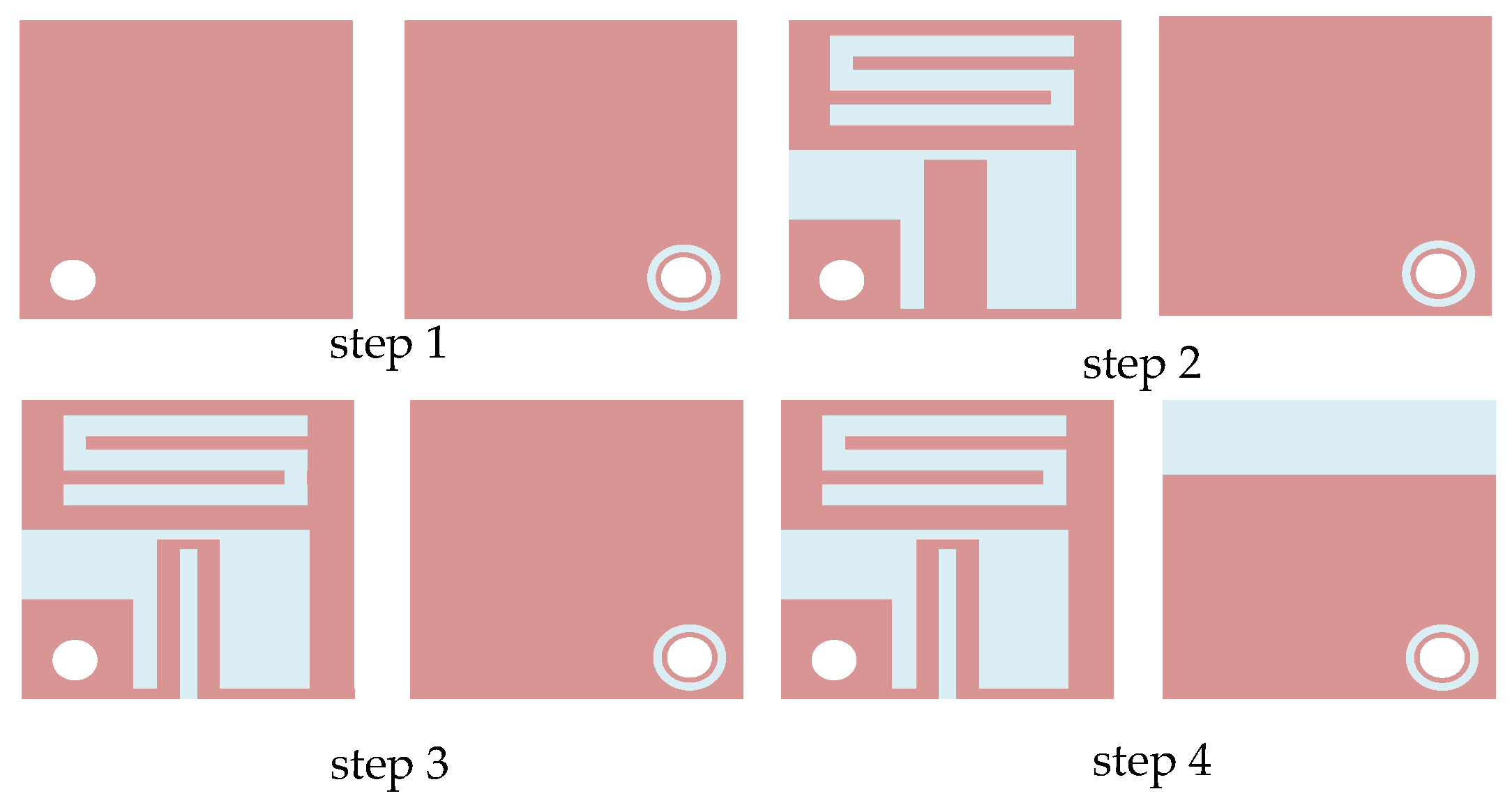
3.1. Antenna Structural Design

The antenna was designed on a Rogers RT 5880 (Rogers Corporation, Chandler, AZ, USA) ( ε r = 2.2, loss angle tangent = 0.0009) substrate with a thickness of 0.13 mm. In order to avoid direct contact between the radiating patch of the antenna and the human body, which in turn affects the performance of the antenna, we also added a layer of 0.4 mm thick silicone on top of the antenna to be used as a cover layer. The antenna presented herein is a compact microstrip patch antenna with a zigzag structure, making it highly suitable for implantable devices and an ideal choice for implantable antennas in Wireless Body Area Networks (WBANs). The radiating patch, which incorporates zigzag slots and various rectangular slots, achieves compactification and bandwidth enhancement of the antenna. The rectangular slots on the ground plane improve impedance matching, as shown in Figure 3. The detailed parameters of the antenna are outlined in Table 2. A coaxial feeding point with a diameter of 0.3 m is located at the bottom left corner of the antenna patch at position P (x = −2.2 mm, y = −2.2 mm), as indicated by the white circle in the Figure 3.
The design process of the antenna is depicted in Figure 4. Slots are introduced on the radiating patch, and zigzag structures are added to achieve compactification while maintaining broadband characteristics. Each step in the design process corresponds to a specific reflection coefficient.
Initially, F-shaped and S-shaped zigzag slots are introduced on the rectangular radiating patch to extend the antenna’s current path and induce resonance. As shown in Figure 5, the antenna resonates at 2.73 GHz, but the resonant frequency is too high, and the operating bandwidth does not cover the ISM band. In step 3, an additional rectangular slot is introduced on the radiating patch, reducing the antenna’s resonant frequency and achieving compactification. However, the bandwidth is narrow, and the reflection coefficient is poor. In step 4, a rectangular ground plane is used to expand the antenna’s bandwidth. The antenna’s operating frequency band is 2.08–2.64 GHz, fully covering the required frequency band. From the before mentioned design steps, it is evident that the introduction of zigzag-shaped rectangular slots on the radiating patch achieves antenna compactification. Further, by adding open rectangular slots on the radiating patch and ground plane, the antenna gains good impedance matching and operating bandwidth, resulting in a compact broadband implantable antenna.

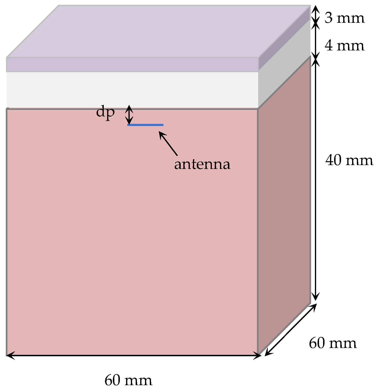
3.2. Antenna Silicone Layer Design

Implantable antennas differ from most antennas operating in free space in that they function within the human body, a complex dielectric environment composed of skin, fat, muscle, and other tissues. Each tissue has different propagation and absorption characteristics for electromagnetic waves, with varying dielectric constants and conductivities. Therefore, the addition of a covering layer is of significant importance in the design of implantable antennas. With a covering layer, direct contact between the antenna’s radiator and human tissue can be avoided. Due to the special working environment, implantable antennas have strict requirements for safety and reliability during the design process. Thus, to meet the safety requirements of implantable antennas, the material used for the covering layer must exhibit biocompatibility characteristics, meaning it can exist within the human body for extended periods without causing adverse reactions, ensuring compatibility with the human body, and further optimizing antenna performance.
Silicone is a material with high biocompatibility, similar in viscosity to glue, and is suitable for the design of implantable antennas. Its excellent flexibility allows it to adapt well to the deformation of human tissues, reducing potential damage to surrounding tissues and enhancing the antenna’s safety and comfort, thereby providing robust characteristics. Additionally, silicone has good corrosion resistance, ensuring safety and extending the antenna’s lifespan. At 2.45 GHz, the relative dielectric constant of silicone is 3.02 [17]. When using silicone as the covering layer material, it effectively isolates the antenna from muscle tissue while ensuring the antenna retains biocompatibility, thereby achieving the minimization of the antenna to the greatest extent possible.
To determine the thickness of the silicone layer used, the reflection coefficient of the antenna under different thicknesses was simulated using simulation software. As shown in Figure 6, as the thickness of the silicone layer increases, the antenna’s resonant frequency shifts toward the high-frequency end, and the bandwidth of the antenna is also expanded. When the thickness h1 is increased to 0.4 mm, the antenna’s operating frequency band is 2.08–2.64 GHz. Further increasing the thickness of the silicone layer does not significantly change the antenna’s resonant frequency or operating frequency band. Therefore, a 0.4 mm silicone layer is used to minimize the antenna’s volume while ensuring antenna biocompatibility.

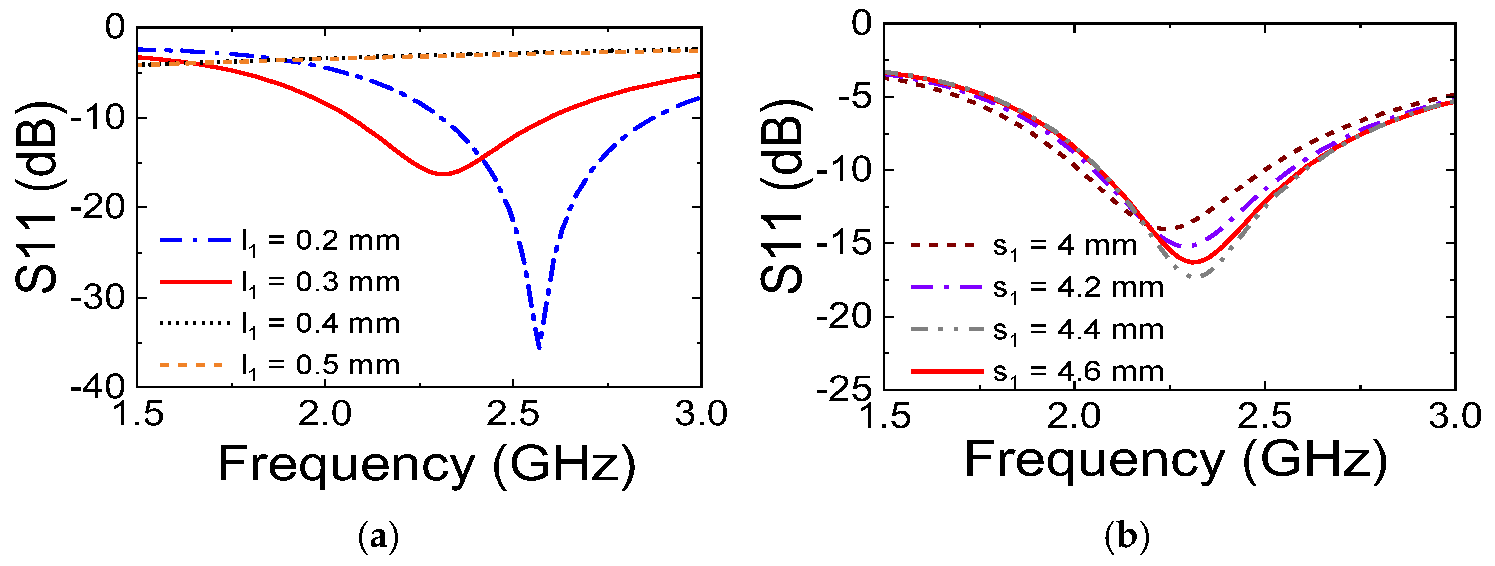
3.3. Antenna Parameter Analysis

The antenna designed in this study introduces rectangular slots of various shapes on the radiating patch to achieve compactification and bandwidth enhancement, ensuring good impedance matching for the implantable antenna. To better investigate the impact of slotting on antenna performance, this paper conducts a study and analysis of the parameters of the S-shaped slot.
The influence of the S-shaped slot with different widths on the antenna’s reflection coefficient is depicted as shown in Figure 7a. When l1 = 0.2 mm, the antenna’s resonant frequency is relatively high and does not fully cover the ISM band (2.4–2.48 GHz). However, when l1 = 0.3 mm, the antenna’s resonant frequency decreases, and the operating frequency band fully covers the ISM band, with an increase in the antenna’s bandwidth. If the width of the slot is further increased, the antenna will not resonate at the corresponding operating frequency band. Analysis indicates that the width of the S-shaped slot affects the antenna’s resonant frequency and operating bandwidth, with optimal performance achieved when its width is 0.3 mm. With the increase of s, the antenna’s resonant frequency shifts. When the length of the S-shaped slot is increased to 4.4 mm, the antenna’s resonant frequency is more ideal. However, further increases in length result in a narrower bandwidth and poorer impedance matching. Therefore, it is analyzed that altering the length of the S-shaped slot affects the antenna’s resonant frequency, impedance matching, and operating bandwidth.
From the analysis of the parameters of the S-shaped slot, it is evident that both the length and width of the slot impact the antenna’s operating bandwidth and impedance matching. Consequently, by conducting relevant parameter analysis, the optimal values for the designed antenna parameters can be determined. All parameters of the antenna designed in this paper are presented in Table 2.

4. Discussion

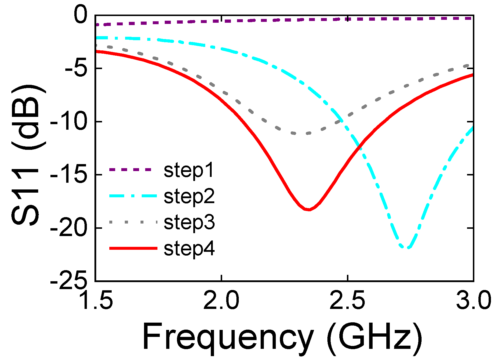
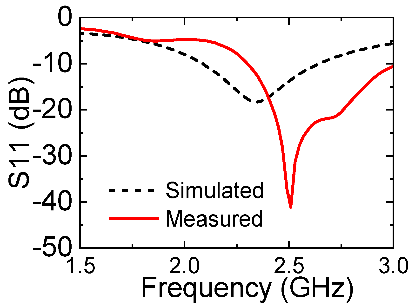
4.1. Reflection Coefficient of the Antenna

The prototype diagram of the antenna is shown in Figure 8, where a coaxial cable is used for antenna feeding. The s11 parameter of the antenna is measured using a vector network analyzer. To minimize the impact of the surrounding environment on the antenna test, the pork is fixed on foam for experimentation. Foam, being a porous material that includes air, has a dielectric constant close to that of air. As depicted in Figure 9, the designed antenna is implanted into the pork, and the other end of the coaxial cable is connected to the vector network analyzer via an SMA interface.
A comparison between the actual measurement and simulation results of the antenna’s reflection coefficient is presented in Figure 10. The operating frequency band of the antenna in pork with s11 less than −10 dB is 2.3–3.03 GHz (703 MHz). Compared to the simulation results, the resonant frequency of the antenna has shifted, and the relative bandwidth of the antenna in pork has reached 28%, which is an improvement over the 23.8% relative bandwidth observed in the simulation. Therefore, the experiments confirm that the operating frequency band of the proposed antenna fully covers the required ISM band, and the antenna exhibits better impedance matching after being implanted into pork. The actual measurement results are consistent with the simulation results. Of course, the analysis of the experimental results indicates that there is a certain degree of error between the actual measurement and simulation of the antenna, mainly due to the higher fat content in pork compared to human muscle tissue, which affects the dielectric characteristics of the testing environment. Another reason is the gap between the antenna and the pork tissue, because the antenna cannot be completely fixed during the implantation process, making it difficult for the antenna to fully conform to the muscle tissue as in the simulation model. Additionally, the antenna itself is very small in size, which may lead to certain errors during the antenna’s processing and welding.

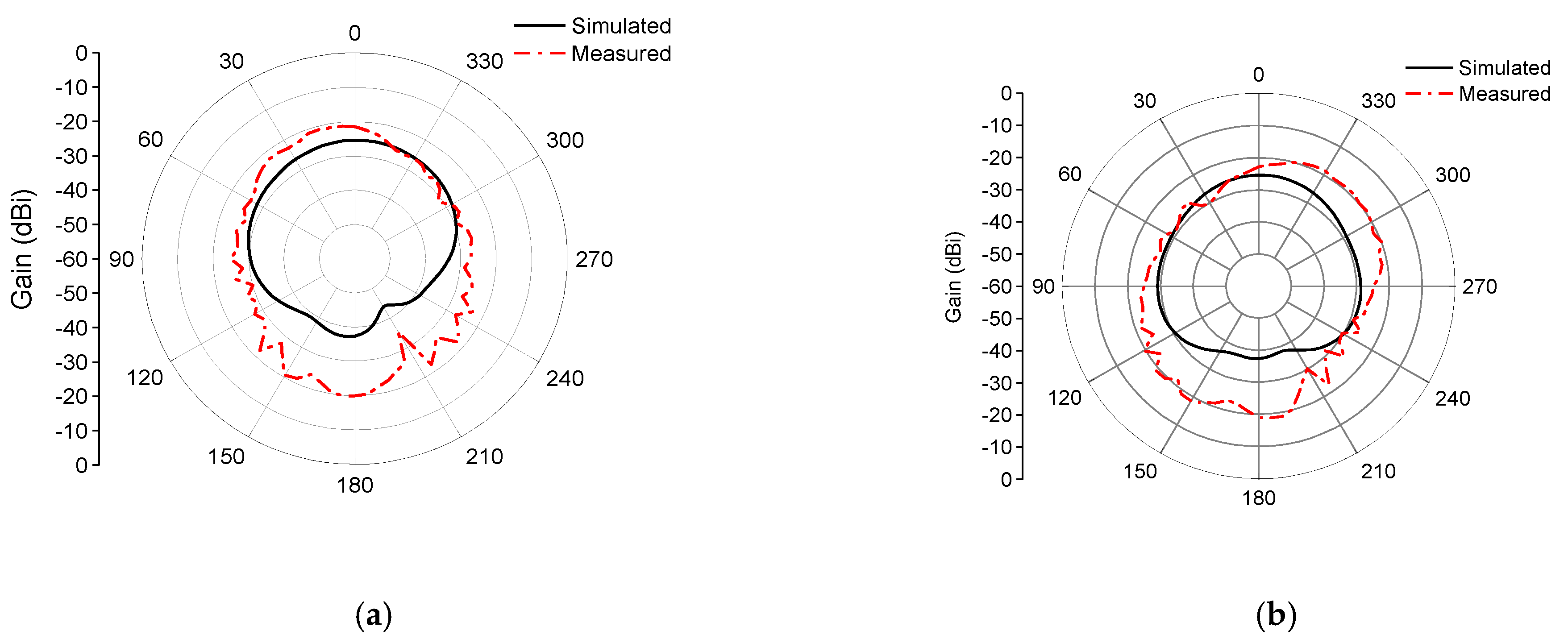
4.2. Radiation Direction Map of the Antenna

The radiation pattern of the antenna was measured in a microwave anechoic chamber. When measuring the radiation pattern of the antenna in the chamber, the designed antenna was implanted into the pork, and the other end of the coaxial cable was connected to the chamber’s turntable via an SMA interface. Due to the weight of the pork block itself, the antenna cannot be directly fixed to the turntable after being implanted into the pork. Therefore, foam boards and foam cotton were used to fix the antenna. The final experimental setup is shown in Figure 11.
The simulated and measured radiation patterns of the antenna at the 2.45 GHz frequency point are shown in Figure 12. The simulated and measured patterns in the xoz and yoz plane indicate that the maximum radiation is achieved at 180°, with the null at 210°. The maximum gain of the antenna is −19.92 dB. The test results show that the simulated and measured radiation patterns of the designed antenna are in good agreement, and the antenna achieves omnidirectional radiation within its operating environment. Compared to the xoz plane, the omnidirectional radiation in the yoz plane is more ideal. The antenna’s omnidirectional radiation characteristic enables communication in all directions within the complex human body.
The test results of the antenna radiation pattern show that the antenna gain is overall larger. The reason for this error may be the frequent startup of the testing equipment during the actual measurement process, leading to instability of the experimental turntable during rotation. This also results in a serrated appearance in the xoz and yoz planes, and a rightward shift in the yoz plane. Such errors are within an acceptable range.

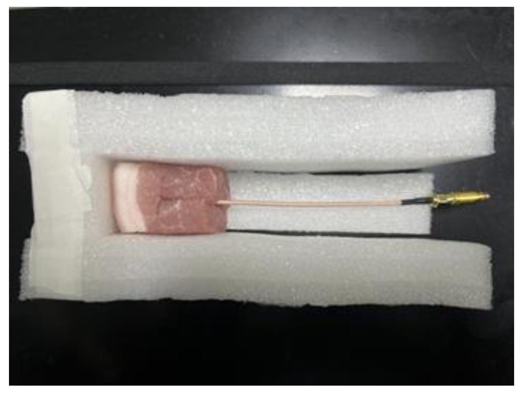
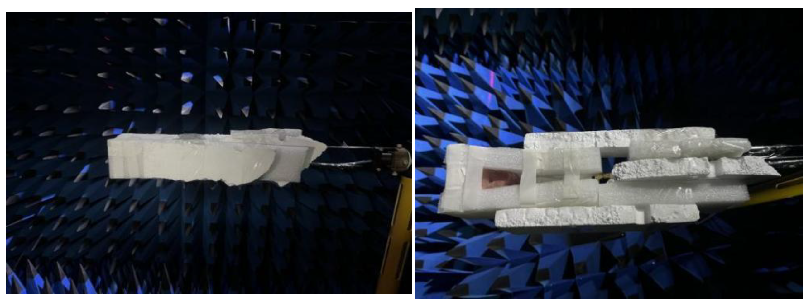
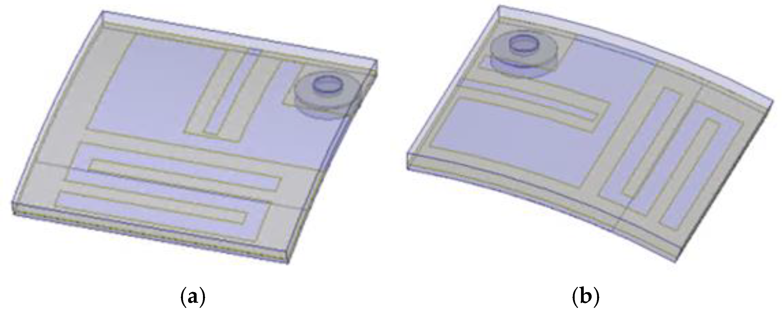
4.3. Antenna Bending Test Setup and Test

Since the human body is a dynamic system, it is constantly moving and changing, and the tissue layers will also change with the movement of the human body. The implantable antenna may undergo a certain degree of deformation due to the movement of the surrounding muscle tissue, which may affect the performance of the antenna. It is necessary to study the structural deformation of the antenna to ensure the stability of the antenna. Therefore, we used simulation software to build a cylindrical model and then conformalized the antenna onto the cylindrical model to simulate the bending test of the antenna. As shown in Figure 13, the antenna is bent on the cylindrical model to simulate and measure the s11 and radiation pattern of the antenna when bent in the X- and Y-direction.

4.3.1. Reflection Coefficient Measurement Results

Cylindrical models with different radii were used to simulate the degree of antenna bending. Therefore, the radius of the cylinder determines the degree of antenna bending, and the smaller the radius, the greater the degree of bending. The experimental results show that the reflection coefficient of the antenna is consistent when the antenna is bent in different directions. The operating frequency band of the antenna shifts to a lower frequency with the increase of the bending degree, and the operating bandwidth narrows. As shown in Figure 14, the designed antenna was tested for bending on cylinders with radii (Rs) of 20, 18, 16, and 14 mm. The resonant frequency of the antenna shifts to a lower frequency with the increase of the bending degree. When the antenna is bent on a cylinder with a radius of 14 mm, the operating frequency band of the antenna is 1.95–2.49 GHz (540 MHz), which fully covers the ISM band.
Due to the small size of the antenna, the specific degree of bending of the antenna during the actual measurement process cannot be visually displayed through the bending radius as in the simulation. The antenna was bent to the greatest extent possible while ensuring that the antenna structure was not damaged. The actual measurement results after bending the antenna are shown in Figure 15. The resonant frequency of the antenna shifted to a higher frequency, with the resonant frequency in the X-direction shifting to 2.34–2.92 GHz (580 MHz), and the resonant frequency in the Y-direction shifting to 2.32–2.97 GHz (650 MHz). The actual measured bandwidth of the antenna in the bent state increased compared to the unbent state.
Due to the wide bandwidth of the antenna during the simulation, although the performance of the antenna is affected to some extent after bending, the operating frequency band of the antenna in the bent state still fully covers the frequency band required for implantable antennas. The reflection coefficient of the antenna at the 2.4–2.48 GHz frequency band meets the design requirements (s11 < −10 dB). Through bending experiments, it is proven that the designed antenna has structural robustness and can maintain a wide operating frequency band and fully cover the ISM band under different degrees of bending deformation.

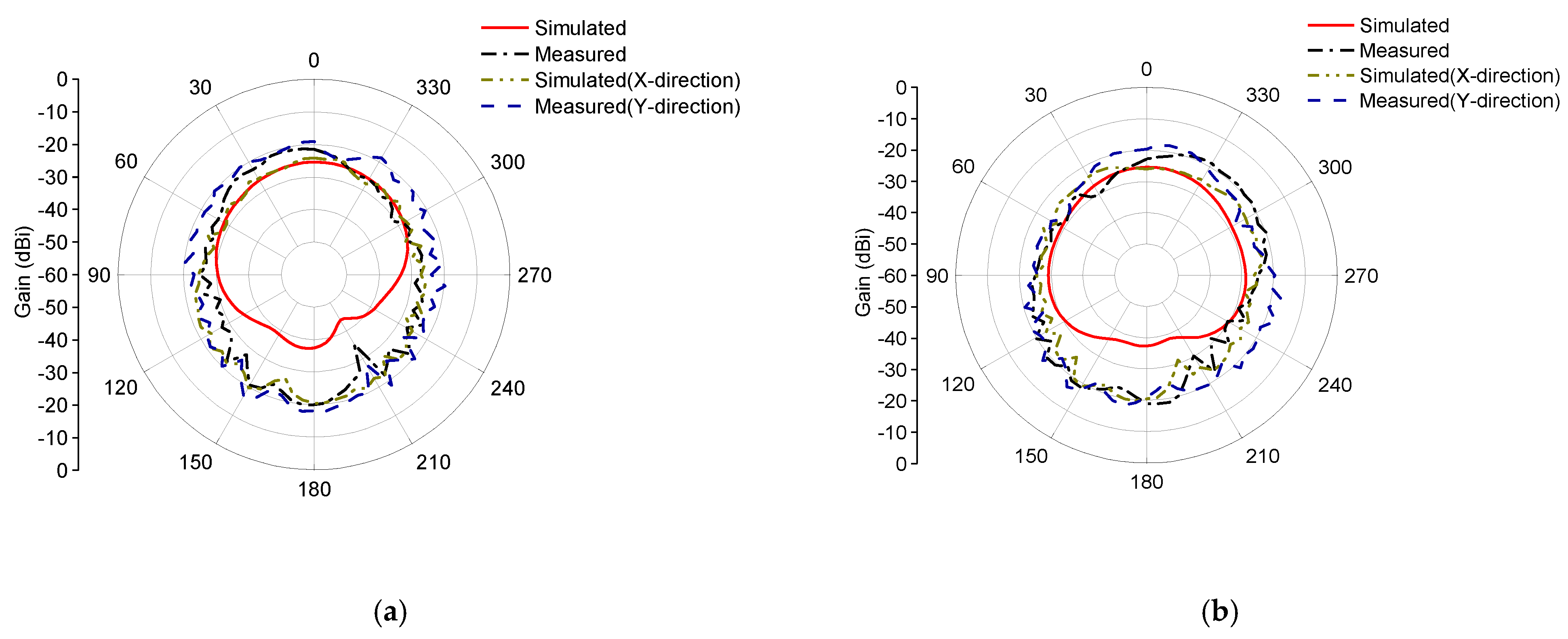
4.3.2. Radiation Direction Map Measurement Results

As shown in Figure 15, the actual measured radiation patterns of the proposed antenna under bending conditions are essentially consistent with those measured under planar conditions. The maximum radiation direction and null position of the antenna can also be maintained under deformation conditions. Additionally, the xoz and yoz plane patterns indicate that the antenna also has good omnidirectional radiation characteristics under bending conditions. Therefore, the analysis of the experimental results shows that the designed antenna meets the design requirements for implantable antennas, and the antenna can maintain stable radiation characteristics regardless of the direction of structural deformation.

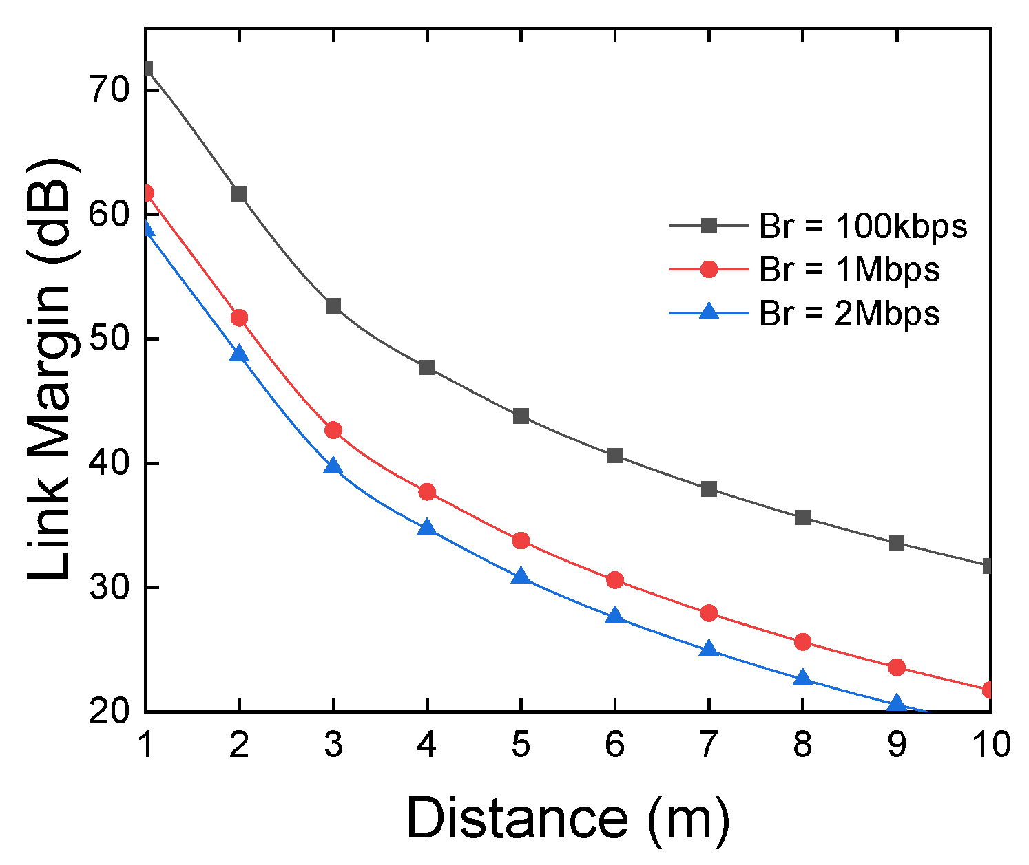
4.4. Wireless Link Budget Analysis

The ability of implantable devices to communicate reliably and effectively with external devices is crucial for the monitoring and transmission of medical data. Therefore, the performance of the implant antenna in actual application scenarios largely depends on its ability to seamlessly transmit recorded real-time data. To determine the wireless telemetry capabilities of the proposed miniaturized broadband implantable antenna, the link budget was theoretically calculated and experimentally evaluated.
The link budget was first theoretically calculated, and Table 3 lists the basic parameters for controlling the communication link survey. A dipole antenna with a gain of 3 dB was used as the receiver to calculate the link budget from the in-body transmitter to the external device scenario. To ensure the safety of the implantable device, according to ICNIRP regulations, the power of the implantable antenna was set to 25 μw (−16 dBm). Other relevant parameters related to the transmitter, receiver, propagation, and signal quality in the link budget calculation are shown in Table 3. Here, A P represents the available power of the antenna, R P represents the power required for antenna operation, K = 1.38 × 10⁻²³ is the Boltzmann constant, and B r represents the transmission rate in Mbps or kbps. The link margin (LM) in the wireless communication system is calculated using the following formula:
R P d B = E b N 0 + K T 0 + B r
A P d B = P T x + G T x + G R x L f
L d B = 20 l o g ( 4 π d λ )
L M d B = A P d B R P d B
The calculated results of the Link Margin (LM) for the antenna at different data rates and transmission distances are depicted in Figure 16. The implantable antenna can easily achieve data transmission rates of 100 kbps and 1 Mbps within a 10 m range, with the calculated LM exceeding 20 dB. When the transmission rate is increased to 2 Mbps, the effective communication range of the implantable antenna can still reach 9 m. Since the implantable antenna is situated in the upper layer of human muscle tissue and the external receiver will be in contact with the skin, the wireless data transmission distance should be less than 5 cm [17]. As shown in Figure. 17, the LM is higher than 58 dB within a 1 m range, allowing for wireless biotelemetry of the implantable antenna.

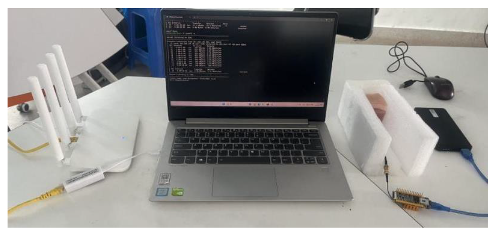
4.5. Wireless Data Transmission Verification

The antenna’s capability to achieve stable data transmission was further experimentally verified using the setup depicted in Figure 17. As shown, one end of the experimental setup consists of an antenna implanted into pork tissue and a Nano Pi Duo2 development board (FriendlyElec, Guangzhou, China) forming a wireless module, while the other end utilizes a common wireless router for data transmission. To comprehensively assess the wireless data transmission capabilities of the implantable antenna, experiments were conducted with the implantable antenna serving both as the receiver and the transmitter.
The iperf3 network performance testing tool was employed on a computer to measure the data transmission rates when the antenna was used as the receiver and the transmitter. The test results, as shown in Figure 18a, indicate that the data transmission rate is faster and more stable when the antenna is used as the receiver compared to when it is used as the transmitter. Additionally, it is evident that the distance between the transmitter and the receiver significantly affects data transmission. There is a noticeable decrease in transmission rate as the transmission distance increases. The fluctuations in transmission rate may be due to interference from other electronic devices and experimental instruments in the laboratory. The communication quality of the wireless communication module was also inspected using the iwconfig command, as shown in Figure 18b. The communication quality of the implantable antenna decreases with increasing communication distance. A slight improvement in communication quality is observed when the distance increases to 9 m, possibly because the antenna is placed on a table outside the laboratory at this distance. The relatively open space may be more conducive to data transmission. The experimental analysis indicates that the communication performance of the implantable antenna is affected by distance, with both communication rate and quality decreasing as distance increases.
Since the actual application scenario for the implantable antenna is within human tissue, the distance between the antenna and external devices will not be too far. Therefore, despite the impact of distance on the antenna’s communication performance, the distance over which the implantable antenna can maintain stable communication meets the actual needs of wireless telemetry.

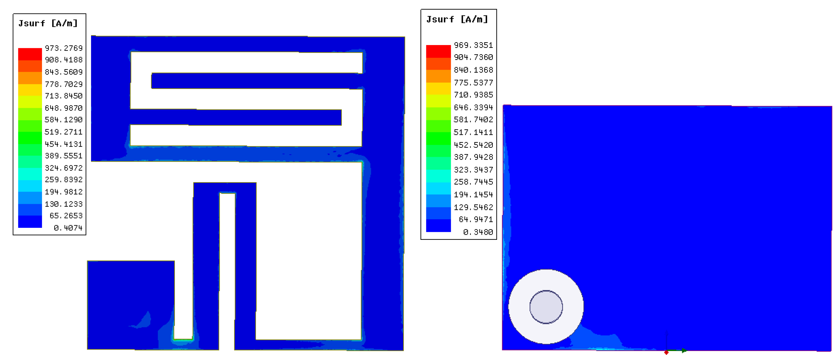
4.6. Antenna Current Distribution and Analysis

Figure 19 shows the surface current distribution of the radiating patch at the top and bottom of the antenna at the 2.45 GHz frequency point. From the figure, it can be seen that the current distribution of the antenna is relatively uniform. We increase the bandwidth of the antenna by adjusting the geometry and size of the antenna to create a uniform current distribution in the operating frequency band. Uniform current distribution results in better impedance matching of the antenna, more stable radiation efficiency, and lower SAR.

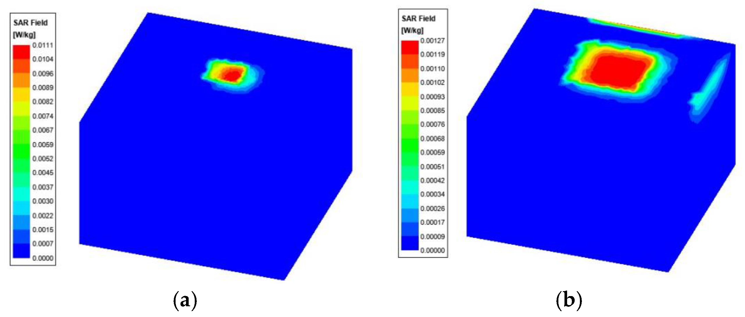
4.7. Specific Absorption Rate (SAR) Measurement and Analysis

Antennas generate electromagnetic radiation during operation, and since implantable antennas operate within human tissue, the radiation they produce is absorbed by the human body, potentially affecting health. Therefore, the SAR value of the implantable antenna must be considered during the design process. SAR is a parameter that measures the absorption of electromagnetic radiation energy by the human body, with units in W/kg. According to the IEEE C95.1-1999 standard, the average SAR value over any 1 g of human tissue should not exceed 1.6 W/kg [17]; according to the IEEE C95.1-2005 standard, the average SAR value over any 10 g of human tissue should not exceed 2 W/kg [18]. The International Commission on Non-Ionizing Radiation Protection (ICNIRP) has regulations on the radiation power of medical implant devices, limiting their maximum input power to 25 μW [19].
To determine the SAR value of the proposed antenna at an input power of 25 μW, we used simulation software to set the input power of the antenna implanted in human muscle tissue to 25 μW. Figure 20 shows that when the input power is 25 μW, the SAR value of the antenna in 1 g of tissue is 0.0111 W/kw, and the SAR value in 10 g of tissue is 0.00127 W/kg. In the literature [20], when the input power of the implantable antenna is set to 25 μW, the SAR value of the antenna in 1 g of tissue at the corresponding frequency of 2.45 GHz is 0.17 W/kg. In the literature [21], when the input power of the implantable antenna is set to 25 μW, the SAR values of the antenna in 10 g of tissue at different frequencies are 0.017, 0.016, and 0.014 W/kg, respectively. By comparing the above literature, the SAR value of the antenna designed in this paper is lower when the input power meets the ICNIRP regulations.
Through simulation analysis and calculation, it can be determined that the maximum input power of the antenna designed in this paper, which complies with the IEEE safety standards for 1 g and 10 g of human tissue, is 6.14 mW and 17.98 mW, respectively, as shown in Table 4. The maximum input power of the antenna at this time is much greater than 25 μW, so this antenna can meet the SAR requirements of both IEEE and ICNIRP standards.
In Table 4, the antenna designed in this study is compared with antennas from papers published in recent years. Compared with the implantable antennas designed in [22] and [8], the antenna designed in this paper has a wider bandwidth and lower SAR values. Although the implantable antenna proposed in [12] has lower SAR values, the antenna designed in this paper has a wider bandwidth and smaller dimensions. Through comparison, the antenna designed in this paper has superior comprehensive performance, featuring small size, wide bandwidth, and low SAR values.

5. Conclusions

This paper presents the design of a compact broadband implantable antenna for Wireless Body Area Networks (WBANs) with an operating frequency band covering the ISM band. By employing slotting techniques, the compactification of the antenna has been achieved, with the proposed antenna volume being only 6 mm× 6 mm× 0.53 mm. A rectangular ground plane is used to further expand the antenna’s operating bandwidth, with a relative bandwidth reaching 28% (703 MHz). The use of silicone material as a covering layer endows the antenna with biocompatibility. Pork was used to simulate the human tissue environment for antenna performance testing. The test results indicate that the antenna possesses omnidirectional radiation characteristics and a wide frequency band. The antenna designed in this paper has a wider bandwidth, lower SAR values, and a smaller size, making it easier to integrate and implant, with higher safety and stronger anti-interference capabilities. This work provides technical support for the development of implantable antennas in WBAN applications and offers new design insights for antennas with high requirements for compactification and biocompatibility.

Author Contributions

Conceptualization, Z.G. and P.C.; methodology, Z.G.; software, Z.G.; validation, Z.G., P.C. and D.W.; formal analysis, Z.G., X.F., X.W.; investigation, Z.G.; resources, Z.G.; data curation, Z.G.; writing—original draft preparation, Z.G.; writing—review and editing, Z.G., P.C. and L.L.; visualization, Z.G.; supervision, P.C.; project administration, P.C.; funding acquisition, P.C. All authors have read and agreed to the published version of the manuscript.

Funding

This work was supported by Fujian Provincial Science and Technology Department’s Industrial Guidance Projects (2024H0018) and the Xiamen Industry–University–Research Subsidy Project (2023CXY0303).

Institutional Review Board Statement

Not applicable.

Informed Consent Statement

Not applicable.

Data Availability Statement

The original contributions presented in this study are included in the article. Further inquiries can be directed to the corresponding author.

Conflicts of Interest

The authors declare no conflict of interest.

References

  1. Faisal, F.; Zada, M.; Ejaz, A.; Amin, Y.; Ullah, S.; Yoo, H. A Miniaturized Dual-Band Implantable Antenna System for Medical Applications. IEEE Trans. Antennas Propag. 2020, 68, 1161–1165. [Google Scholar] [CrossRef]
  2. Cornet, B.; Fang, H.; Ngo, H.; Boyer, E.W.; Wang, H.G. An Overview of Wireless Body Area Networks for Mobile Health Applications. IEEE Netw. 2022, 36, 76–82. [Google Scholar] [CrossRef]
  3. Wang, S.; Deng, W.; Yang, T.; Tian, G.; Xiong, D.; Xiao, X.; Zhang, H.; Sun, Y.; Ao, Y.; Huang, J.; et al. Body-area sensor network featuring micropyramids for sports healthcare. Nano Res. 2022, 16, 1330–1337. [Google Scholar] [CrossRef]
  4. Sui, Y.; Hou, C.; Wang, Y.; Chung, K.L.; Wei, C.; Li, Z.; Zong, W.-H.; Wang, J. A Tissue-Independent Flexible Antenna With Miniaturized Size for Injectable Implants. IEEE Antennas Wirel. Propag. Lett. 2023, 23, 945–949. [Google Scholar] [CrossRef]
  5. Magill, M.; Conway, G.A.; Scanlon, W. Tissue-Independent Implantable Antenna for In-Body Communications at 2.36–2.5 GHz. IEEE Trans. Antennas Propag. 2017, 65, 4406–4417. [Google Scholar] [CrossRef]
  6. Liu, R.-P.; Zhang, K.-L.; Li, Z.-W.; Cui, W.-J.; Liang, W.-B.; Wang, M.-J.; Fan, C.; Zheng, H.-X.; Li, E.P. A Wideband Circular Polarization Implantable Antenna for Health Monitor Microsystem. IEEE Antennas Wirel. Propag. Lett. 2021, 20, 848–852. [Google Scholar] [CrossRef]
  7. Xia, Z.; Li, H.; Lee, Z.; Xiao, S.; Shao, W.; Ding, X.; Yang, X. A Wideband Circularly Polarized Implantable Patch Antenna for ISM Band Biomedical Applications. IEEE Trans. Antennas Propag. 2020, 68, 2399–2404. [Google Scholar] [CrossRef]
  8. Zhang, J.; Das, R.; Hoare, D.; Wang, H.; Ofiare, A.; Mirzai, N.; Mercer, J.; Heidari, H. A Compact Dual-Band Implantable Antenna for Wireless Biotelemetry in Arteriovenous Grafts. IEEE Trans. Antennas Propag. 2023, 71, 4759–4771. [Google Scholar] [CrossRef]
  9. Kamel, A.; Mohamed, A.; Elsadek, H.; ELhennawy, H.M. Miniaturized Triple-Band Circular-Polarized Implantable Patch Antenna for Bio-Telemetry Applications. IEEE Antennas Wirel. Propag. Lett. 2023, 22, 74–78. [Google Scholar] [CrossRef]
  10. Lamkaddem, A.; El Yousfi, A.; Abdalmalak, K.A.; Posadas, V.G.; Segovia-Vargas, D. Circularly Polarized Miniaturized Implantable Antenna for Leadless Pacemaker Devices. IEEE Trans. Antennas Propag. 2022, 70, 6423–6432. [Google Scholar] [CrossRef]
  11. Shah, A.; Zada, M.; Nasir, J.; Yoo, H. Ultraminiaturized Triband Antenna with Reduced SAR for Skin and Deep Tissue Implants. IEEE Trans. Antennas Propag. 2022, 70, 8518–8529. [Google Scholar] [CrossRef]
  12. Mosavinejad, S.; Rezaei, P.; Khazaei, A. A miniaturized and biocompatible dual-band implantable antenna for fully-passive wireless signal monitoring. AEU-Int. J. Electron. Commun. 2022, 154, 154303. [Google Scholar] [CrossRef]
  13. Hertleer, C.; Rogier, H.; Vallozzi, L.; Van Langenhove, L. A Textile Antenna for Off-Body Communication Integrated Into Protective Clothing for Firefighters. IEEE Trans. Antennas Propag. 2009, 57, 919–925. [Google Scholar] [CrossRef]
  14. Bait-Suwailam, M.; Alomainy, A. Flexible Analytical Curve-Based Dual-Band Antenna for Wireless Body Area Networks. Prog. Electromagn. Res. M 2019, 84, 73–84. [Google Scholar] [CrossRef]
  15. Vidhya, S.; Shanthi K, G. Ultra Wideband Flexible Antennas: Design, Performance and Integration for Wireless Body Area Network Applications. Int. J. Microw. Opt. Technol. 2023, 18, 435–443. [Google Scholar]
  16. Ganeshwaran, N.; Jeyaprakash, J.K.; Alsath, M.G.N.; Sathyanarayanan, V. Design of a Dual-Band Circular Implantable Antenna for Biomedical Applications. IEEE Antennas Wirel. Propag. Lett. 2020, 19, 119–123. [Google Scholar] [CrossRef]
  17. Green, R.B.; Hays, M.R.; Mangino, M.J.; Topsakal, E. An Anatomical Model for the Simulation and Development of Subcutaneous Implantable Wireless Devices. IEEE Trans. Antennas Propag. 2020, 68, 7170–7178. [Google Scholar] [CrossRef]
  18. Hayat, S.; Shah, A.; Yoo, H. Miniaturized Dual-Band Circularly Polarized Implantable Antenna for Capsule Endoscopic System. IEEE Trans. Antennas Propag. 2021, 69, 1885–1895. [Google Scholar] [CrossRef]
  19. Iqbal, A.; Al-Hasan, M.; Ben Mabrouk, I.; Basir, A.; Nedil, M.; Yoo, H. Biotelemetry and Wireless Powering of Biomedical Implants Using a Rectifier Integrated Self-Diplexing Implantable Antenna. IEEE Trans. Microw. Theory Tech. 2021, 69, 3438–3451. [Google Scholar] [CrossRef]
  20. Kaim, V.; Singh, N.; Kanaujia, B.K.; Matekovits, L.; Esselle, K.P.; Rambabu, K. Multi-Channel Implantable Cubic Rectenna MIMO System with CP Diversity in Orthogonal Space for Enhanced Wireless Power Transfer in Biotelemetry. IEEE Trans. Antennas Propag. 2023, 71, 200–214. [Google Scholar] [CrossRef]
  21. Iqbal, A.; Al-Hasan, M.; Ben Mabrouk, I.; Denidni, T.A. Self-Quadruplexing Antenna for Scalp-Implantable Devices. IEEE Transactions on Antennas and Devices. IEEE Trans. Antennas Propag. 2024, 72, 2252–2260. [Google Scholar] [CrossRef]
  22. Yousaf, M.; Ben Mabrouk, I.; Zada, M.; Akram, A.; Amin, Y.; Nedil, M.; Yoo, H. An Ultra-Miniaturized Antenna with Ultra-Wide Bandwidth Characteristics for Medical Implant Systems. IEEE Access 2021, 9, 40086–40097. [Google Scholar] [CrossRef]
Figure 1. Three layer tissue model of the human body.
Applsci 15 01385 g001
Figure 2. Measurement device.
Applsci 15 01385 g002
Figure 3. Structural diagram of the proposed antenna.
Applsci 15 01385 g003
Figure 4. Design process of the proposed antenna.
Applsci 15 01385 g004
Figure 5. Reflection coefficients corresponding to each design step.
Applsci 15 01385 g005
Figure 6. Reflection coefficients of the antenna with varying silicone layer thicknesses.
Applsci 15 01385 g006
Figure 7. Analysis of the impact of different antenna parameters on the reflection coefficient; (a) l1, (b) s1.
Applsci 15 01385 g007
Figure 8. Prototype diagram of the designed antenna.
Applsci 15 01385 g008
Figure 9. Experimental setup for measuring the s11 of the proposed antenna.
Applsci 15 01385 g009
Figure 10. Measured reflection coefficient of the proposed antenna in pork.
Applsci 15 01385 g010
Figure 11. Experimental setup for measuring the radiation pattern of the proposed antenna.
Applsci 15 01385 g011
Figure 12. Simulated and measured radiation patterns of the designed antenna; (a) xoz, (b) yoz.
Applsci 15 01385 g012
Figure 13. Antenna bending deformation; (a) X-direction, (b) Y-direction.
Applsci 15 01385 g013
Figure 14. Reflection coefficient of the designed antenna after bending; (a) X-direction, (b) Y-direction.
Applsci 15 01385 g014
Figure 15. Simulated and measured radiation patterns of the designed antenna; (a) xoz, (b) yoz.
Applsci 15 01385 g015
Figure 16. Link margin analysis for the proposed antenna.
Applsci 15 01385 g016
Figure 17. Measurement device for wireless data transmission.
Applsci 15 01385 g017
Figure 18. (a) Transmission rate, (b) transmission quality.
Applsci 15 01385 g018
Figure 19. Antenna current distribution.
Applsci 15 01385 g019
Figure 20. Average SAR distribution of the proposed antenna in human tissue; (a) SAR in 1 g of tissue, (b) SAR in 10 g of tissue.
Applsci 15 01385 g020
Table 1. Dielectric properties of different human tissues.
TissueRelative Dielectric Constant ( ε r )Relative Permeability
[ σ (S/m)]
Loss Angle Tangent
Skin38.11.430.283
Fat5.280.10.145
Muscle52.71.740.242
Table 2. Parameters of the proposed antenna.
ParameterSize (mm)ParameterSize (mm)ParameterSize (mm)
W6s14.4s70.2
L6s20.4s80.3
G4.5s32s92.8
l10.3s41.5s102
h0.13s50.5s113
h10.4s63r0.3
Table 3. Link budget parameters of the proposed antenna.
ParametersVariableValue
Frequency F r (GHz)2.45
Transmitter power P T x −16
Transmitter antenna gain G T x −23.8
Receiver antenna gain G R x 3
Distance d ( m ) 1–10
Temperature T 0 ( K e l v i n ) 273
Noise power density N 0 ( d B / H z ) 203.93
Ideal-BPSK E b / N 0 9.6
Free space path loss L f ( d B ) Distance dependent
Available power A P ( d B ) Distance dependent
Required power R P ( d B ) Adaptive (bitrate)
Table 4. Comparison of the antenna proposed in this paper with the other literature.
ReferenceYearSizeRelative Bandwidth (MHz)1 g SAR
(W/kg)
[17]202018.74 mm × 16 mm × 2.4 mm4.4%-
[22]20215 mm × 5 mm × 0.528 mm3.3%340.42
[12]20228.5 mm × 8.5 mm × 1.27 mm3.5%207
[20]202315 mm × 15 mm32.6%324.4
[8]20235 mm × 5 mm× 0.635 mm15.5%785
[21]202412 mm× 14.5 mm × 0.13 mm1.4%-
This paper 6 mm × 6 mm × 0.53 mm28%260.68
Disclaimer/Publisher’s Note: The statements, opinions and data contained in all publications are solely those of the individual author(s) and contributor(s) and not of MDPI and/or the editor(s). MDPI and/or the editor(s) disclaim responsibility for any injury to people or property resulting from any ideas, methods, instructions or products referred to in the content.

