1. Introduction
The pipe jacking method is a trenchless underground pipeline installation technique, with advantages, such as a short construction period and minimal environmental impact, leading to significant economic benefits [
1]. In recent years, with increasing engineering demands, pipe jacking construction has been evolving towards larger diameters and longer distances. In long-distance pipe jacking, the jacking force is one of the key parameters for the selection of pipe segments, the jacking machine, and the working shaft [
2]. Typically, the jacking force comes from the front resistance and the frictional resistance. As the jacking distance increases, the frictional resistance around the pipe also increases, thus increasing the required jacking force [
3], particularly in ultra-long-distance pipe jacking [
4]. If a precise calculation of the jacking force can be achieved, it will significantly contribute to practical engineering applications.
Currently, many scholars have conducted extensive research on grouting for friction reduction in pipe jacking. In terms of the slurry materials and interaction between slurry and soil, Wei et al. [
5] and Namli and Guler [
6] analyzed the properties of a thixotropic slurry, the grouting mechanism, and the use of a bentonite slurry to reduce the jacking resistance. Huang et al. [
7] conducted experiments showing that the slurry can reduce the friction resistance in saturated sandy soil to 63.1%. Yu et al. [
8] analyzed the relationship between the microscopic structure of slurry and friction resistance through laboratory tests, finding that friction resistance increases with time.
The effectiveness of grouting lubrication in pipe jacking largely depends on the selected grouting material. Currently, commonly used grouting materials include a bentonite slurry, cement grout, polymers, and composite slurries. Bentonite slurry is composed of bentonite, CMC (carboxymethyl cellulose), soda ash, and water, characterized by its swelling and thixotropic properties. Bentonite primarily consists of potassium, calcium, and sodium, montmorillonite, with a typical concentration of approximately 5%. When mixed with water and stirred, bentonite forms a suspension. When static, the montmorillonite particles transition from a dispersed state to a gel structure. Upon agitation, the particle structure is disrupted and redistributes, forming a viscous and flowable colloidal liquid. Once the suspension is stationary again, the gel structure re-forms, a property known as thixotropy. Due to its low cost and excellent performance, the bentonite slurry is the preferred material for pipe jacking projects. Cement grout is one of the most basic and commonly used materials in pipe jacking grouting. It has good flowability and strength, enabling it to form a solid structure during the grouting process, effectively reinforcing the soil layer, and improving the bearing capacity and stability of the soil. Polymers primarily consist of materials, such as an epoxy resin slurry and polyurethane slurry and are highly suitable for engineering projects that require excellent reinforcement effects, impermeability, and high durability. The composite slurry mainly includes a cement–sodium silicate slurry and cement–sodium silicate–fly ash slurry. It has a short settling time and high early strength, along with strong fluidity at the beginning, making it suitable for soil layers that require rapid reinforcement and projects with high environmental protection requirements.
In terms of the application of grout in friction reduction for pipe jacking, Zhou et al. [
9] studied the variation pattern of the jacking force under grouting conditions in silty strata through model tests. The tests showed that the viscosity and condensation force of the slurry play a major role in reducing the friction resistance and surface settlement. As the slurry settles or consolidates, the liquid phase (usually water) starts to drain or evaporate, causing the solid particles to come closer together. This process results in an increase in density and the development of internal forces within the slurry. These forces can influence the stability, pressure distribution, and overall performance of the slurry in its application. Wang et al. [
10] conducted detailed research and discussion on the slurry scheme for large-diameter, long-distance pipe jacking based on the construction of the Hong Kong–Zhuhai–Macau Bridge tunnel at the Gongbei site. Through the research, the engineers significantly reduced the friction resistance in practical engineering and solved the problem of excessive jacking force.
The grouting process is as follows. At the beginning of the grouting, we need to pressurize first, then jack. During the process, we need to pressurize and jack simultaneously and regrout timely. An appropriate amount of friction-reducing slurry is injected into the outer wall of the pipe section through the grouting annular pipe. By using a multi-point symmetrical grouting method, the slurry can be evenly distributed in the gap between the outer wall of the pipe section and the surrounding soil, thereby reducing the friction resistance between the pipe section and the soil and lowering the jacking force.
The main technical parameters of grouting are as follows:
- (1)
Grouting Volume: This parameter quantifies the relationship between the pipe jacking length and the thickness of the grout layer. By dynamically monitoring the grouting volume, jacking length, and grout layer thickness, the actual friction-reducing effect of the grouting can be evaluated.
- (2)
Grouting Pressure: During the grouting process, it is essential to strictly control the grouting pressure. On the one hand, if the pressure is too low, the grouting effect may not be achieved. On the other hand, if the pressure is too high, it may fail to form an effective grout layer and could cause grout leakage (overflow).
- (3)
Grouting Speed: The grouting speed is influenced and controlled by several factors, including the arrangement of the grouting holes, the formation of the slurry sleeve, and the jacking speed.
There are generally two methods for grouting in long-distance pipe jacking:
- (1)
Double-layer Grouting Method: The double-layer grouting method effectively reduces friction resistance by forming a protective layer between the slurry and the surrounding soil. This method first injects a consolidation grout behind the jacking head. As the jacking head and pipe advance, the consolidation grout gradually hardens to form a solid shell. Then, an expansion device compresses the consolidation grout, forming a strong protective layer. Finally, grout is injected into the gap between this protective layer and the pipe to ensure the integrity of the grout sheath. This method requires two types of slurry to be stored and injected separately, with consolidation grout primarily used for support and lubrication and supplementary grout used for further lubrication [
11].
- (2)
Pipe Membrane Pushing Method: This method installs a pipe with a plastic membrane inside at the rear of the tunneling machine. During the jacking process, the plastic membrane is continuously drawn out from the pipe, and grout is injected between the membrane and the pipe to facilitate pipe sliding, avoiding uneven grouting and grout leakage.
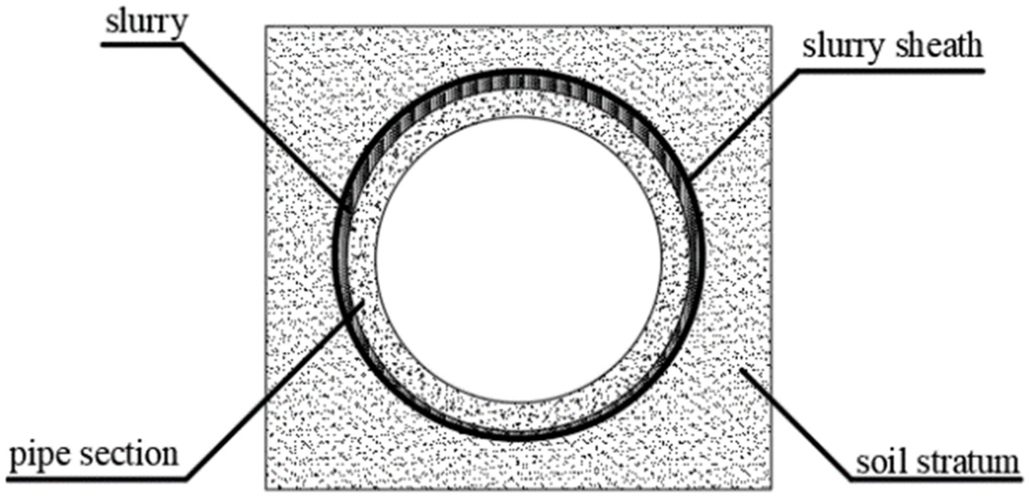
Regardless of the grouting material or method used, the similar grouting-friction-reduction processes work as follows: after the grout comes into contact with the soil, the grouting pressure causes the free water in the grout to permeate into the cracks of the surrounding soil, leading to water loss in the grout [
12]. As the permeation process continues, the grout gradually transforms into a gel-like substance, filling the voids in the soil. During this permeation process, a dense permeation layer forms between the grout and the soil, causing the solid particles in the grout to adhere to this layer, forming a low-permeability slurry sheath. This reduces water loss from the grout. The combined structure of the slurry and the permeation layer is referred to as the grout sheath [
12], as shown in
Figure 1.
The grout sheath transmits the liquid pressure, which exceeds the underground water pressure to the soil particles, and the effective stress generated by this process compacts the soil. Meanwhile, the hydraulic pressure of the grout also supports the borehole wall, maintaining its stability and preventing collapse.
Therefore, the mechanism of grouting mainly involves two aspects: on one hand, the grout provides lubrication between the pipe and the surrounding soil, thereby reducing the frictional resistance during the jacking process; on the other hand, grouting fills the gaps between the pipe and the soil, and the grouting pressure supports the soil, reducing its deformation, thus enhancing the stability of the soil.
In the calculation of jacking force considering grout friction reduction, the most common method is presented in
Section 2 [
13]. This method assumes that the circumferential friction of the pipe is uniformly distributed and uses an imprecise range of average unit frictional resistance between the pipe’s outer surface and the soil to account for the friction reduction. This method cannot consider the depth at which the pipe is buried, which is a significant parameter that influences the friction values. To address these limitations, some scholars have proposed new methods to enhance the accuracy. Li et al. [
14] derived a calculation formula for the additional stress in soil caused by grouting pressure under self-weight conditions based on Terzaghi’s theory of earth pressure. Wang et al. [
15] proposed a method to determine the three common slurry ring shapes for a circular pipe and introduced a segmental method to calculate the corresponding friction resistance.
However, in practice, the distribution of friction resistance around the pipe is continuous and more complex, which can affect the calculation results, especially in the analysis of friction resistance for ultra-long pipe jacking, leading to non-negligible errors. The friction is influenced not only by the grouting, but also by the depth. It is necessary to improve the common method through a numerical analysis, especially by accounting for both the grouting and the depth at which the pipe is buried.
This paper first presents the common theoretical calculation method adopted in China. Then, finite element analysis is employed to simulate the jacking force in long-distance pipe jacking, obtaining the jacking force values under different interface friction angles to simulate the effect of the grouting. The common theoretical method about the friction resistance is improved based on the simulation results to take into account both the grouting and the depth. The improved theoretical method evaluates the friction by calculating interface friction angles through the friction-reduction effect of grouting and normal stress distribution. The numerical and improved theoretical results are compared with the common method that assumes an imprecise range of average unit frictional resistance.
3. Case Study
3.1. Example Verification
To ensure the reliability of the proposed numerical model, example verification was performed using a case provided in the article by Cao et al. [
16].
The details of the case are provided in the article [
16]. The method of processing the numerical simulation is similar to the subsequent simulation process. However, there are two main differences: the length of the pipe is 100 m in this example verification, which is significantly shorter than the following simulation; the bottom burial depth is 9.6 m, which is significantly shallower than the following simulation. The partial results are illustrated in
Figure 3 and
Figure 4. According to the statistics in the article [
16], the soil stratum through which the pipe traverses is silty clay. As shown in
Table 1, the average frictional resistance ranges between 5 kN/m and 8 kN/m; these values are used to calculate the theoretical results, determining the minimum and maximum values. Similarly, according to
Table 2 [
17], the interface friction angle ranges from 0.2 to 0.3; these two values are used to calculate the numerical results, determining their corresponding minimum and maximum values.
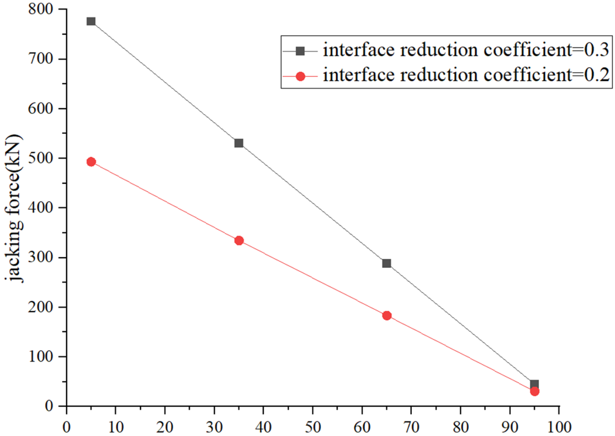
The interface reduction coefficient is set to 0.2 in
Figure 3. The numerical result of the distribution is approximately circular and conforms to prevalent viewpoints [
18] and Chinese regulations [
13]. The distribution of axial force under different reduction coefficients is shown in
Figure 4. It can be observed that as the distance from the launch shaft increases, the jacking force decreases approximately linearly, indicating that the distribution of shear stress along the pipe is relatively uniform. Additionally, the jacking force increases by approximately 1.5 times when the interface reduction coefficient is increased by the same factor, which aligns with common sense.
From
Table 3, the numerical results are compared with the theoretical results introduced in
Section 2 and the field-measured results provided in the referenced article. It can be observed that the numerical results closely align with the theoretical results, and the field-measured results fall within both ranges.
From the above example, the numerical results presented below were validated for reliability and trustworthiness. It should be noted that the main differences between the example verification and the subsequent simulation are the length and the depth of the pipe. If the length is significantly increased or the depth is considerably deeper, the theoretical results may lead to significant errors.
3.2. Overview of the Numerical Model
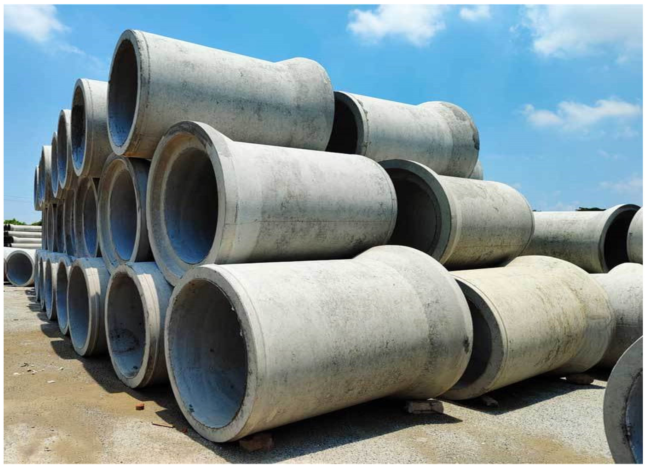
In an electric utility corridor project located in a soft soil area, “F”-type steel reinforced concrete pipes with an outer diameter of 3600 mm and an inner diameter of 3000 mm are planned for use. “F”-type-steel-reinforced concrete pipes are named after the F-type joint that they use. Due to their excellent sealing performance and durability, they are widely used in urban engineering projects [
19] as shown in
Figure 5. Each pipe section is 2.5 m in length, with a total jacking length of 625 m. The soil layer of the pipe consists of silty clay.
The finite element software PLAXIS 3D (Edition 2017) is used for the calculation. Considering that the impact range of the tunnel construction is 3 to 5 times the larger value between the height and width of the tunnel section, the model’s soil domain is set to a height of 43.6 m (the depth is a boundary between two strata) and a width of 60 m to eliminate boundary effects. The ten-node elements are set. In order to consider the different effect of the grout, the interface reduction coefficients are set to different values.
3.3. Soil Parameter Settings
The soil adopts the Mohr–Coulomb model with a “drained” condition. The groundwater level is located 11 m below the ground surface. The basic parameters of the soil layers are shown in
Table 4. The soil model is shown in
Figure 6.
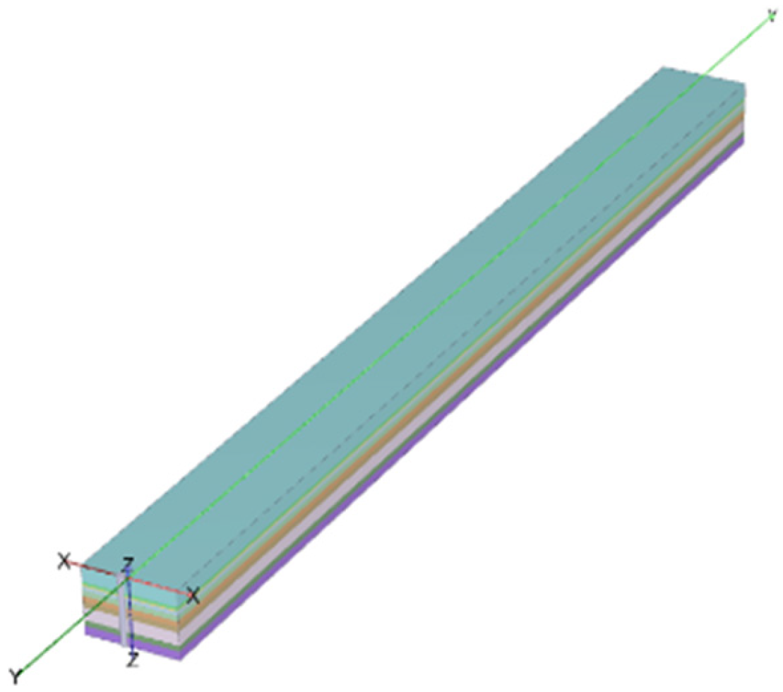
3.4. Structure Parameter Settings
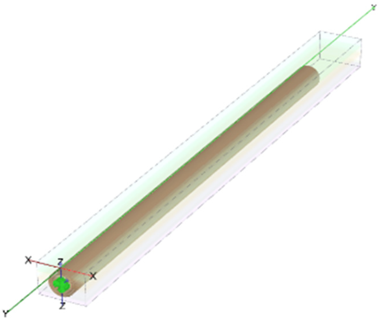
The pipe is modeled using linear elastic plate elements. The outer diameter is 3600 mm, the inner diameter is 3000 mm, and the longitudinal length is 625 m. The bottom burial depth is 24.4 m. The structure model is shown in
Figure 7.
The unit weight of the pipe (γ) is 24.5 kN/m
3, and the thickness is 0.3 m. In order to consider the effect of the grouting, the interface between the pipe and the surrounding soil is set. Typically, the range of the interface reduction coefficient between the pipe and the surrounding soil is listed in
Table 2 [
17].
Different interface reduction coefficients are set on the interface to simulate different effects of grouting. The relationship between the interface friction angle and the internal friction angle can be calculated as
In the formula,
is the interface friction angle;
is the internal friction angle;
is interface reduction coefficient;
In this case, the strata through which the pipe traverses consist of silty clay, and the groundwater level is located 11 m below the ground surface, resulting in wet soil conditions. According to
Table 2, the Interface reduction coefficients between the pipe and the surrounding soil should be set within the range of 0.2 to 0.3. However, the friction-reduction effect of grouting may not be effective in long-distance pipe jacking. To address potential issues and ensure the safety of practical engineering applications, additional considerations may be required. Therefore, six interface reduction coefficients are set separately by 0.2, 0.24, 0.28, 0.32, 0.36, and 0.4.
To simulate the pressure exerted by the soil on the front surface of the pipe, a force perpendicular to the surface is applied. The magnitude of this force increases along the vertical direction to reflect the rise in the lateral soil pressure with depth.
3.5. Mesh and Phases Settings
The element mesh density is medium. The first phase is the initial phase, the soil elements outside the pipe interior, plate elements, the force implied on the front surface, interface elements are activated, and the calculation type is the procedure. The equilibrium of the forces is not guaranteed, and thus, the second phase is set without any change in the model only to consider the force equilibrium with the “plasticity” calculation mode. There are three modes to select, namely “plasticity”, “consolidation”, and “safety”. The plasticity mode considers an elastoplastic drained or undrained analysis, without considering consolidation. The consolidation mode considers a time-dependent analysis of deformation and excess pore pressure. The safety mode calculates the overall safety factor using the strength-reduction method. The simulation does not consider the effect of the pore pressure and the strength-reduction method; thus, the first mode is selected. In order to exert the frictional resistance, a 10 cm displacement along the longitudinal direction of the whole pipe is applied in the third phase.
3.6. Results Analysis
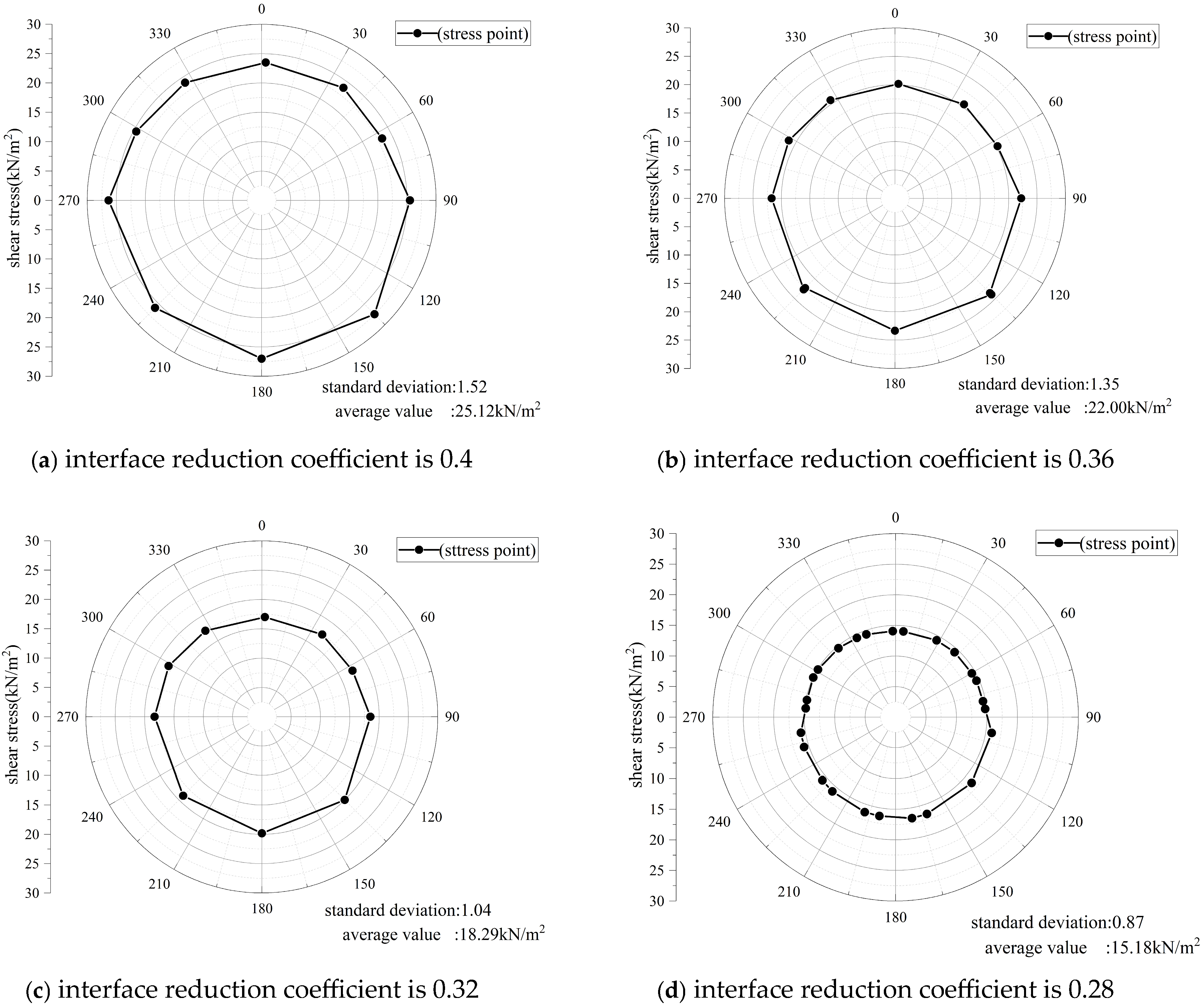
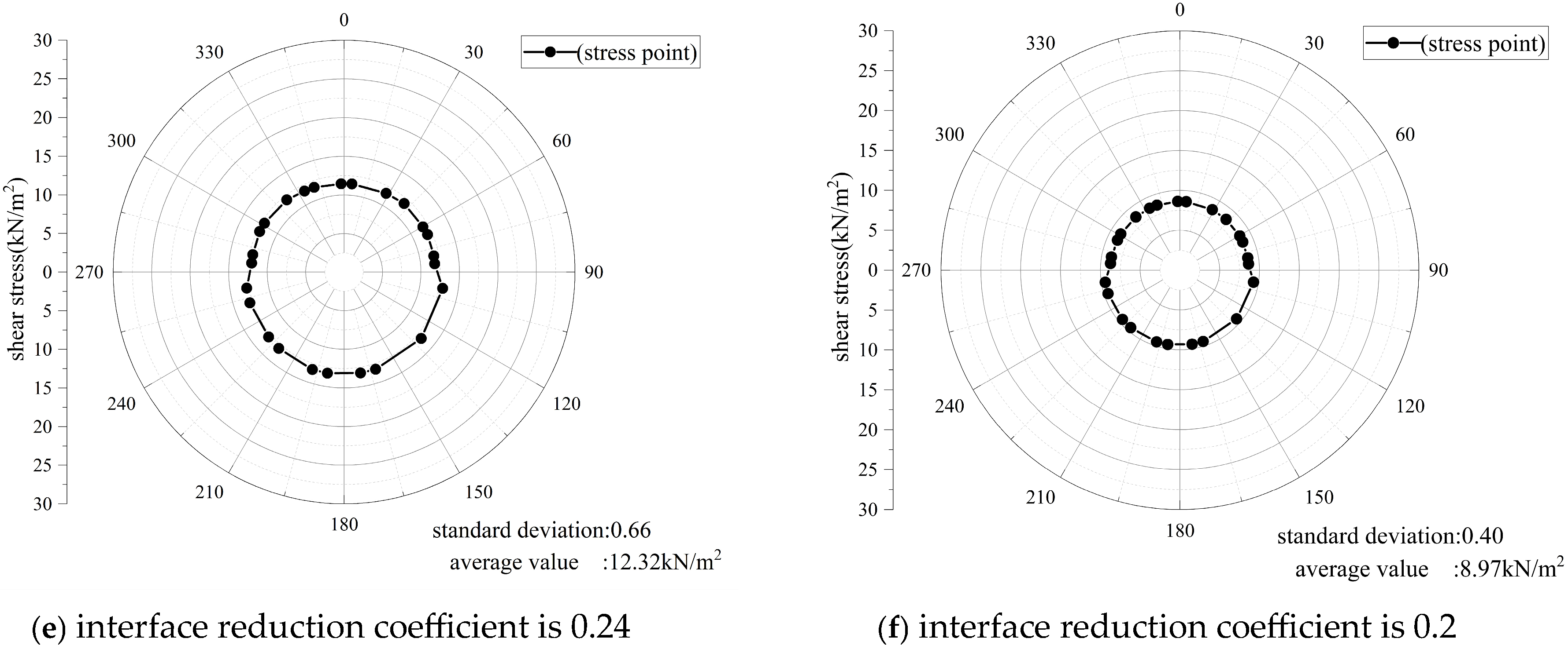
Figure 8 shows the distribution of sectional frictional resistance at the same position (100 m from the launch shaft) under different interface reduction coefficients.
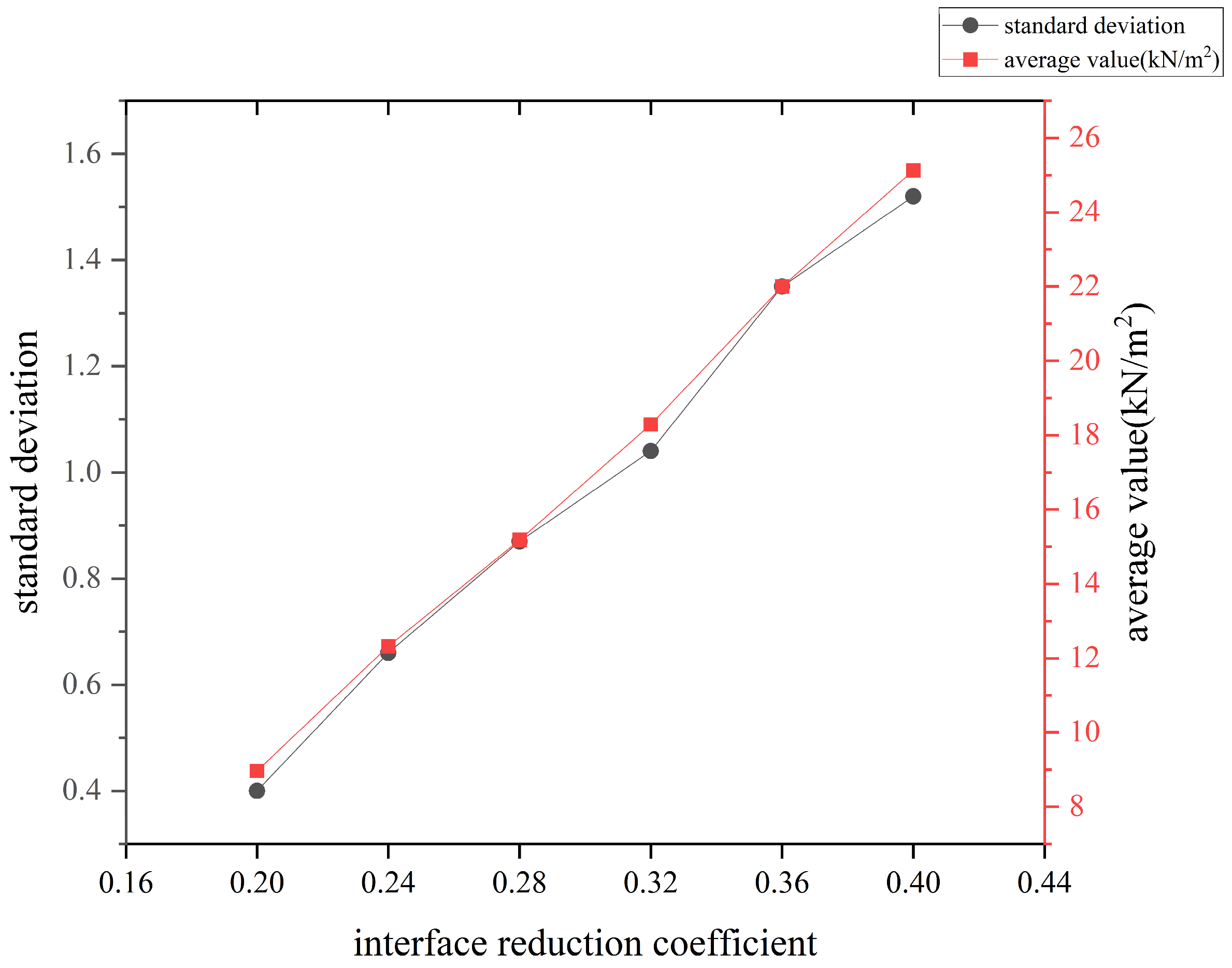
Figure 9 illustrates the variation in the standard deviation and average value with respect to different interface reduction coefficients. It can be observed that as the coefficient increases in the range of 0.2 to 0.4, the average frictional resistance around the pipe increases approximately linearly, and the value of the standard deviation of the stress points around the pipe also increases linearly. This reveals that as the interface reduction coefficient increases, the distribution of the stress around the pipe becomes more uneven. Thus, if the interface friction angle is sufficiently large, the variation in shear stress across the same section should be considered.
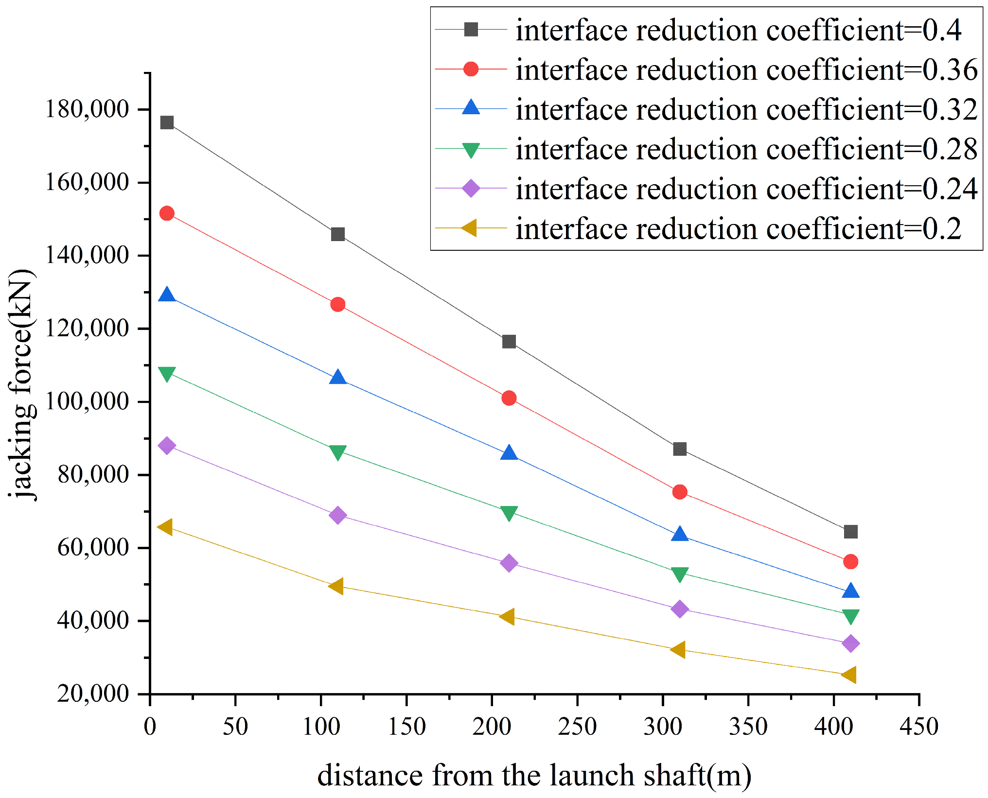
Figure 10 shows the axial jacking force along the length of the pipe under different interface reduction coefficients. It can be observed that as the distance from the launch shaft increases, the reduction in the jacking force slows down, indicating a slight decrease in the frictional resistance around the pipe. The reason may be the difference in displacement between the pipe and the surrounding soil. There should be sufficient relative distance to develop frictional resistance. Since the pipe is not modeled as rigid, the displacement near the launch shaft is greater than that at the pipe’s end, reducing the frictional resistance at the end.
The theoretical and numerical results of the jacking force are summarized in
Figure 11. Regarding the numerical results, as the interface friction angle increases, the total jacking force of the pipe increases approximately linearly. It can be inferred that in long-distance pipe jacking projects, the proportion of front resistance is very small, and the main resistance originates from the frictional resistance between the pipe and the surrounding soil.
The theoretical method is presented in
Section 2, indicating that the frictional resistance is 10 kN/m
2, as shown in
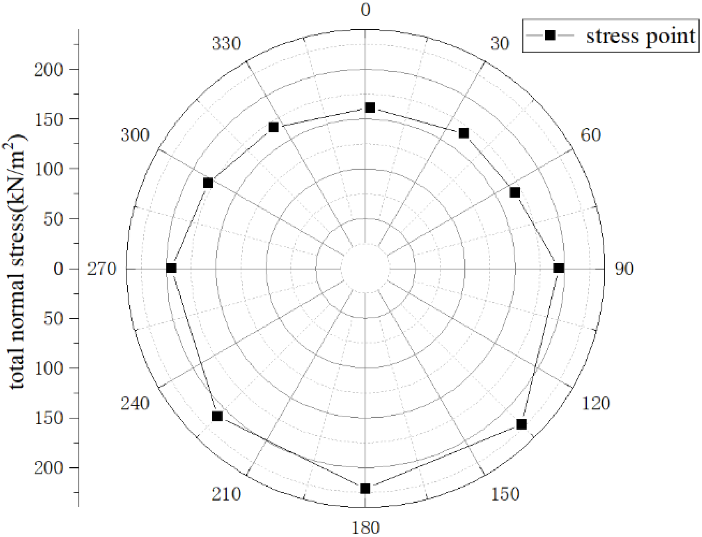
Table 1. The jacking force remains constant because the frictional resistance is defined as a fixed range. The different values can be applied within this range, but the value is too imprecise to select, so the fixed value is applied here. The simulated jacking force is much larger than the theoretical value because the theoretical value does not consider the increasing trend of frictional resistance with the depth of the pipe. In this simulation, the pipe’s bottom end is buried at a depth of 24.4 m, where the normal stress on the interface between the soil and the pipe is quite large, as shown in
Figure 12 (100 m from the launch shaft). This results in significantly larger friction resistance around the pipe, much greater than the average friction resistance between the pipe and soil selected in the theoretical method as shown in
Table 1.
3.7. Improved Theoretical Method for Calculating Frictional Resistance
In long-distance pipe jacking projects, the proportion of front resistance is very small, so it is suitable only to improve theoretical methods for calculating the frictional resistance by the simulation results.
First, the total normal stress can be calculated based on the data in
Table 4. The formula is expressed as
In this formula,
is the total normal stress in the vertical direction;
is the number of soil strata;
is the saturated unit weight of each stratum;
h is the d = thickness of each stratum.
The effective normal stress at both the bottom and the top of the pipe can be calculated. In this case, the effective normal stress is 474 kPa at the bottom and 403 kPa at the top.
Second, the total normal stress can be estimated based on the
. There are many influencing factors here, such as the arching effect of the soil and the difference between the
and
(total normal stress in the lateral direction). In this case, the average total normal stress is 160 kPa (according to
Figure 12, the average total normal stress is higher than 160 kPa, but the data are obtained from 100 m from the launch shaft, and there is a slight decrease in the frictional resistance along the longitudinal direction).
Third, by using the formula presented later, the relationship between the average total normal stress and the frictional resistance is established.
In this formula,
is the average total normal stress;
is the internal friction angle of the soil stratum around the pipe.
In this case, the average internal friction angle is 16.7°, and there are six different values of
to calculate. The results are shown in
Table 5.
Finally, apply the improved
to the Formula (4) to obtain the new answer. And the total jacking force is obtained using Formulas (1) and (2) as the previous theoretical methods. The results are shown in
Table 5.
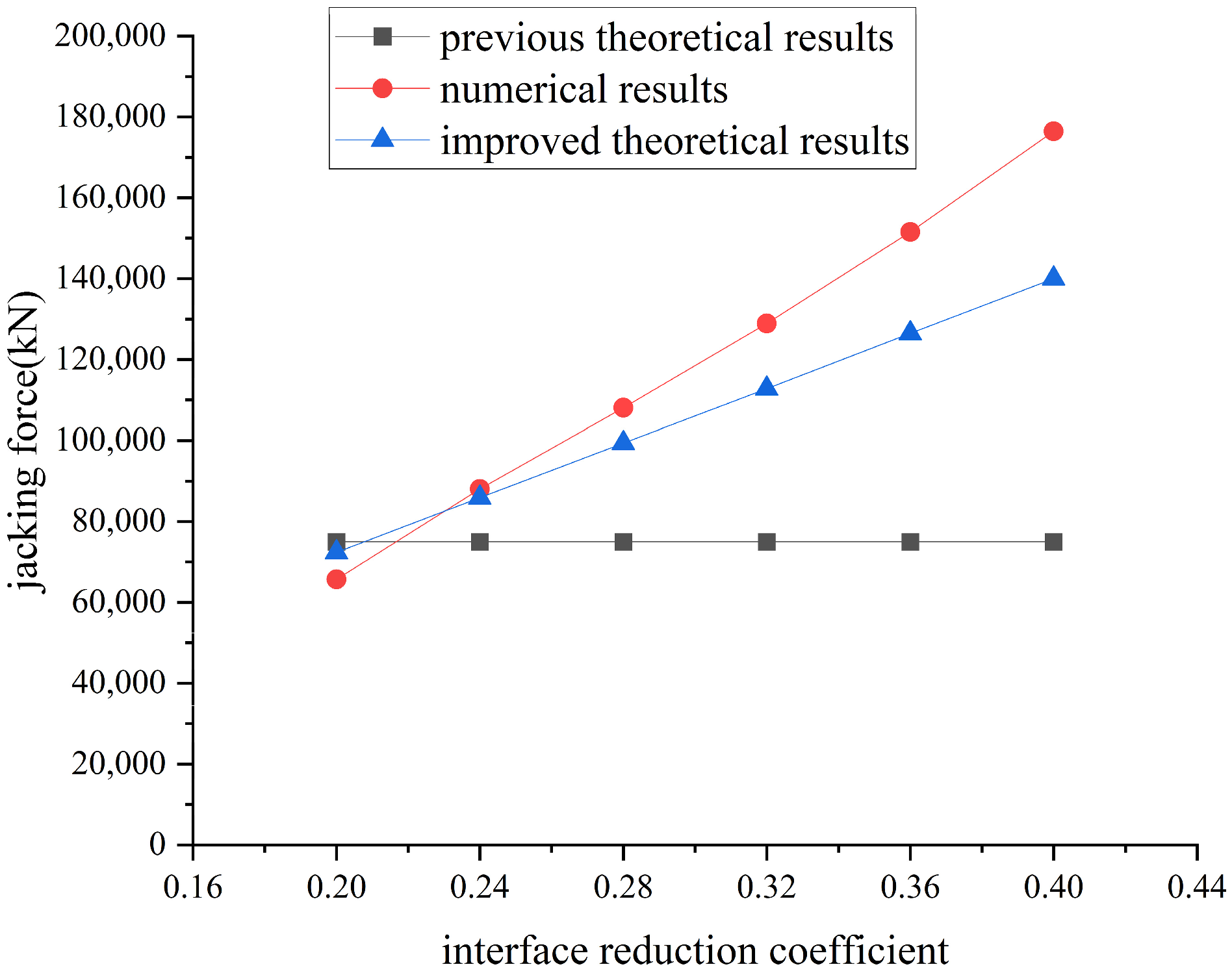
The previous theoretical results, improved theoretical results, and numerical results of the jacking force are summarized in
Figure 13.
In
Figure 13, it is evident that the improved theoretical results exhibit a linear relationship based on different interface reduction coefficients. This trend aligns better with the numerical results, and the discrepancy between the improved theoretical results and the numerical results is significantly smaller compared to the difference between the previous theoretical results and the numerical results.


