

An Analytical Model for the Steady-State Thermal Analysis of Façade-Integrated PV Modules Cooled by a Solar Chimney


 ,
,  ,
,  and
and
Abstract
1. Introduction
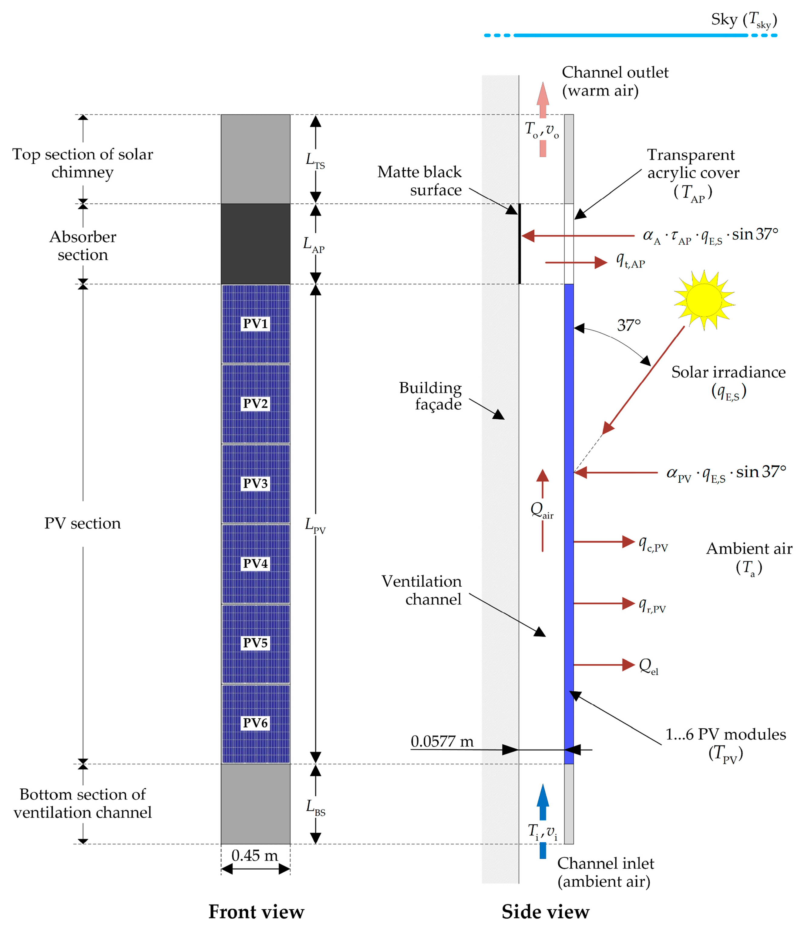
2. Case Study
3. Steady-State Thermal Modeling
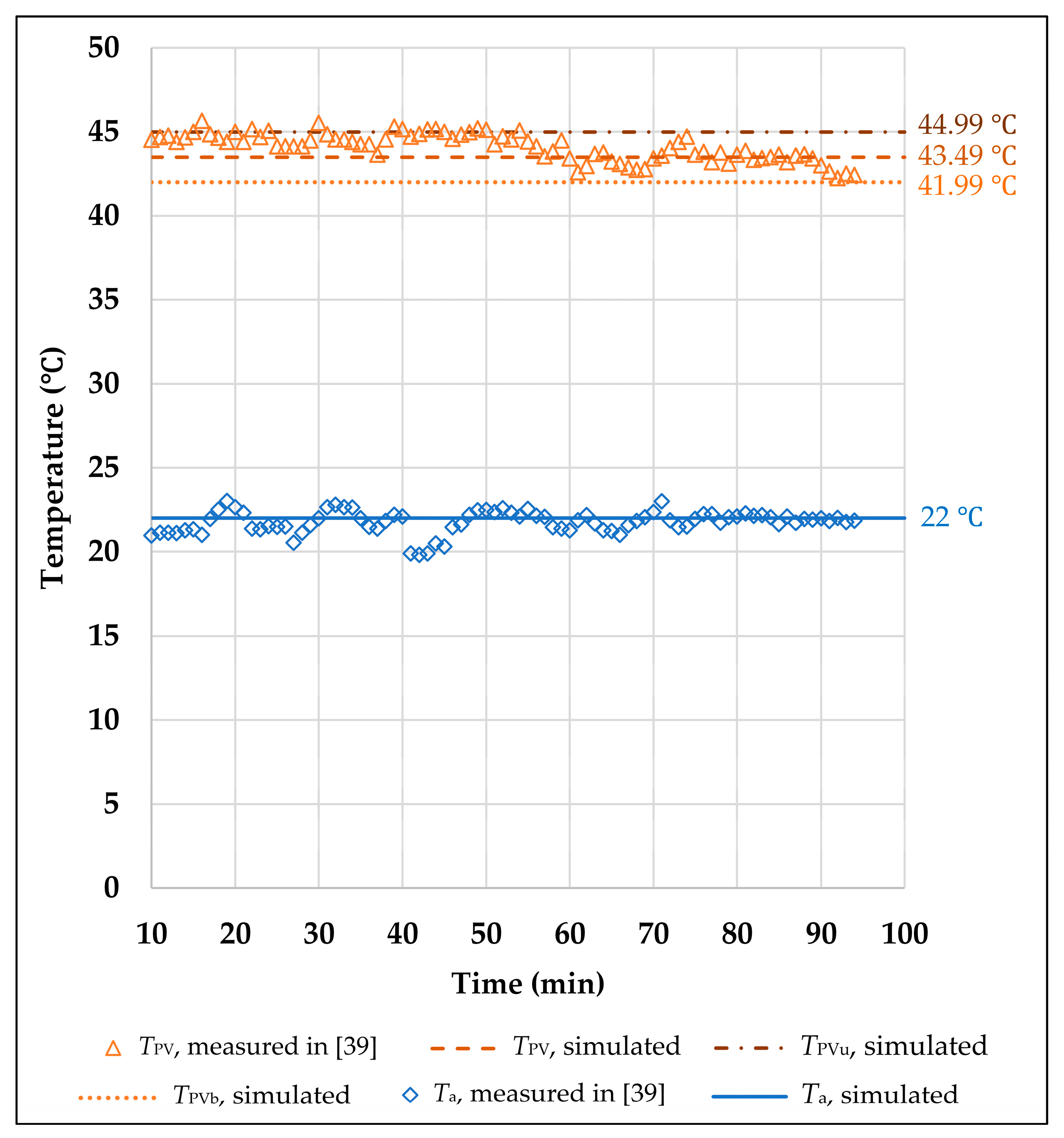
4. Results and Discussion
5. Conclusions
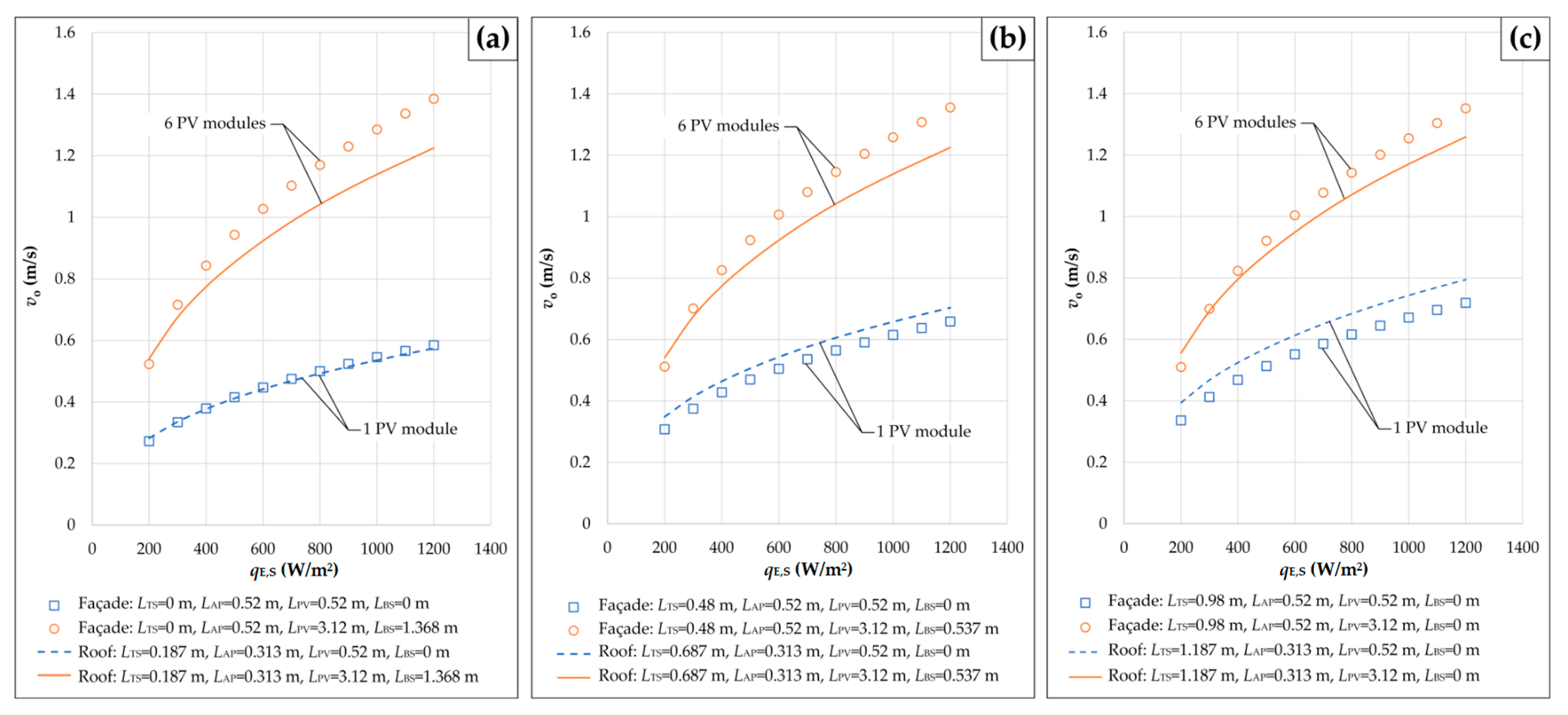
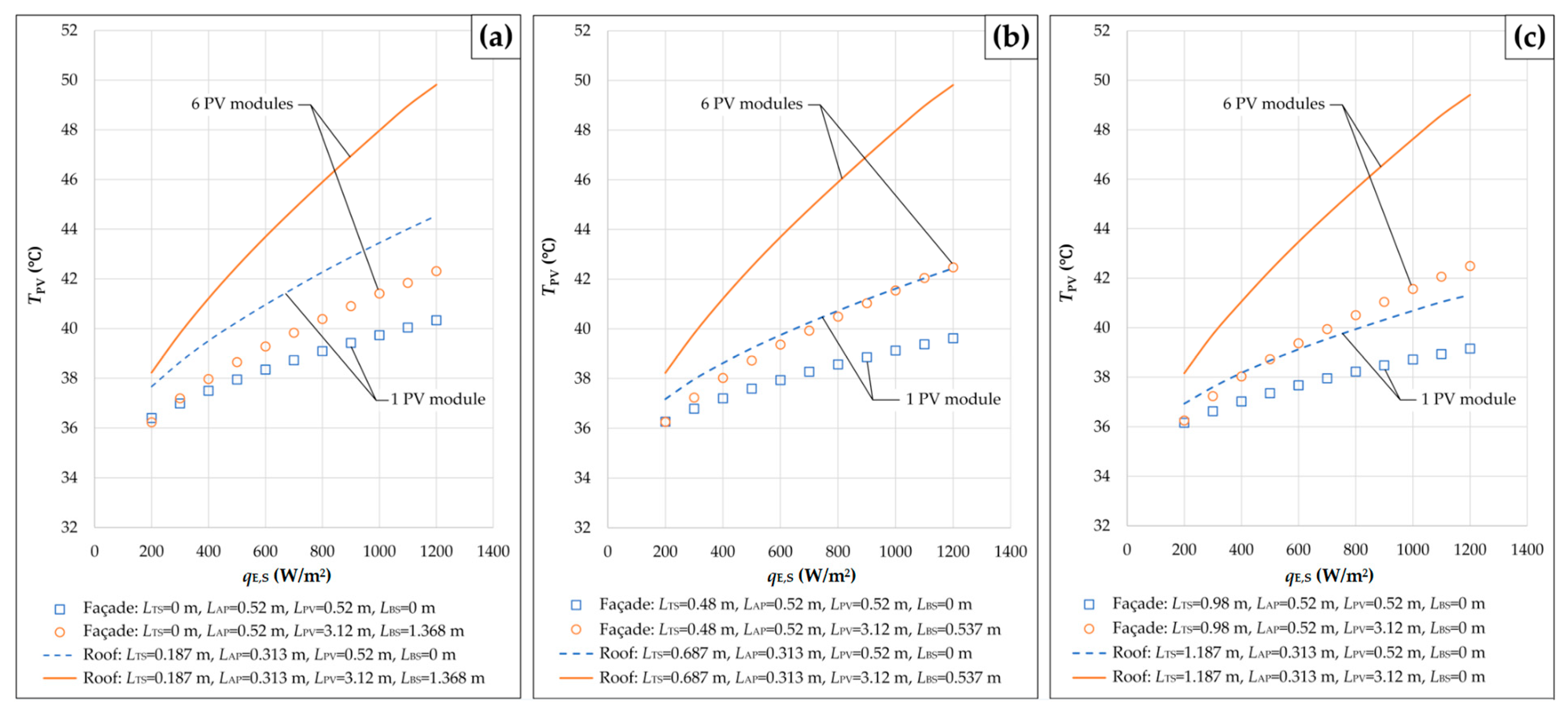
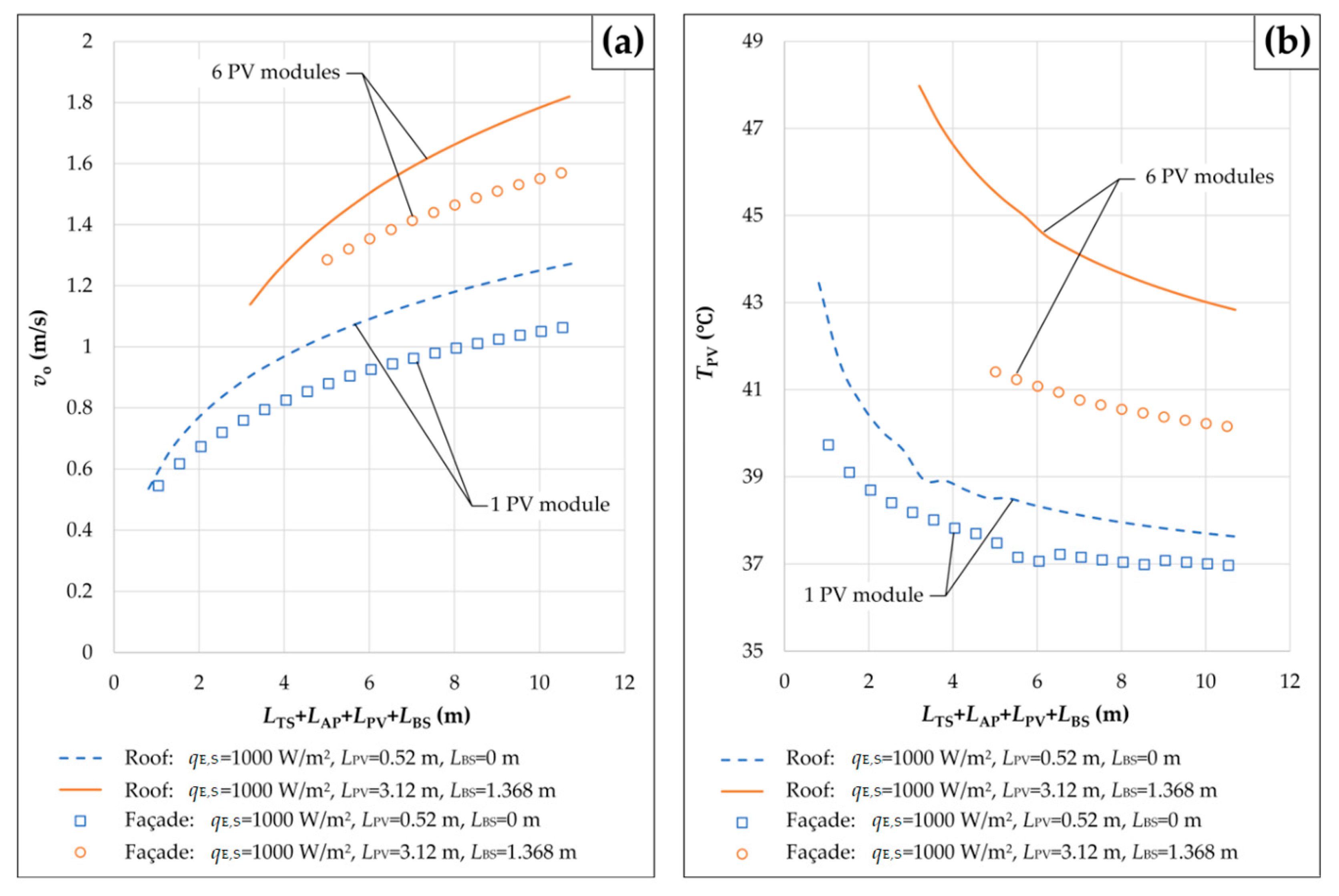
- The velocity of air at the outlet of any solar chimney integrated with PV modules increases with an increase in the solar irradiance and with an increase in the height difference between the outlet and the inlet of the associated ventilation channel. This increase is significantly more pronounced in the case of “Façade” than in the case of “Roof”. In addition, the solar chimney effect on the velocity of air in any ventilation channel is almost negligible for the cases of PV sections with larger numbers of roof- or façade-integrated PV modules. Unlike the air velocity, the average temperature of any PV section increases with increasing solar irradiance and decreases with increasing height of the solar chimney. Moreover, the greater the amount of heat transferred between one PV section and the air in the ventilation channel below it, the smaller the effect of the velocity of air at the outlet of the channel on the average temperature of roof- or façade-integrated PV modules.
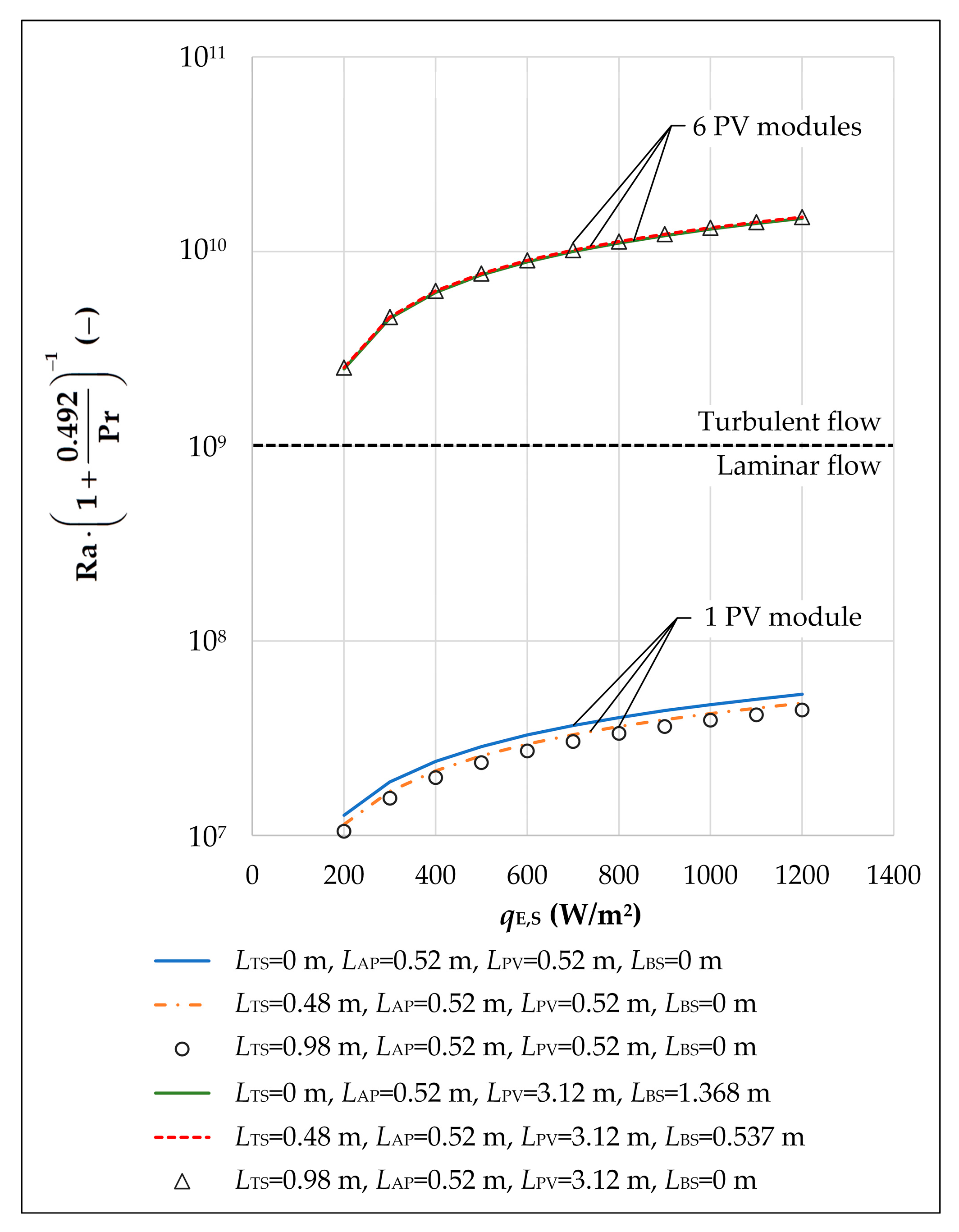
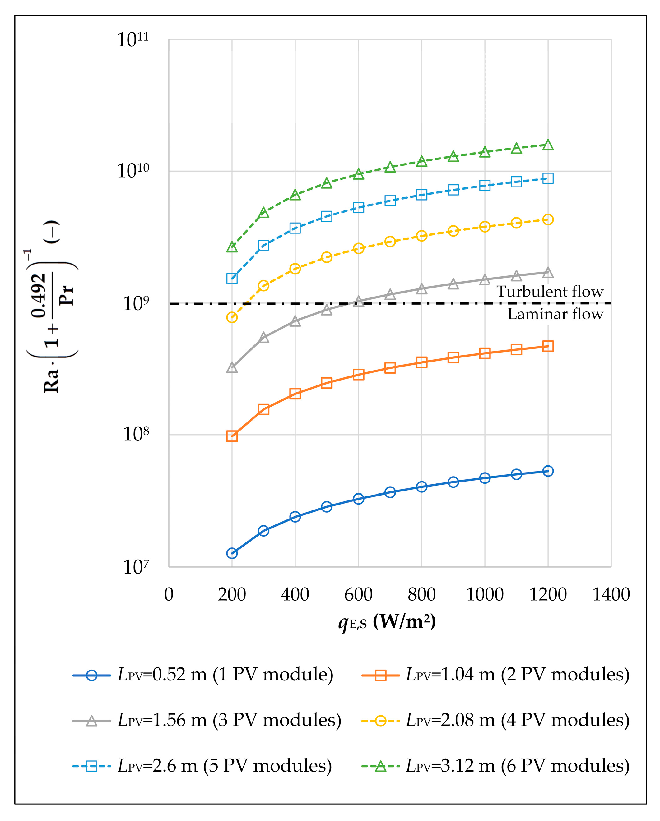
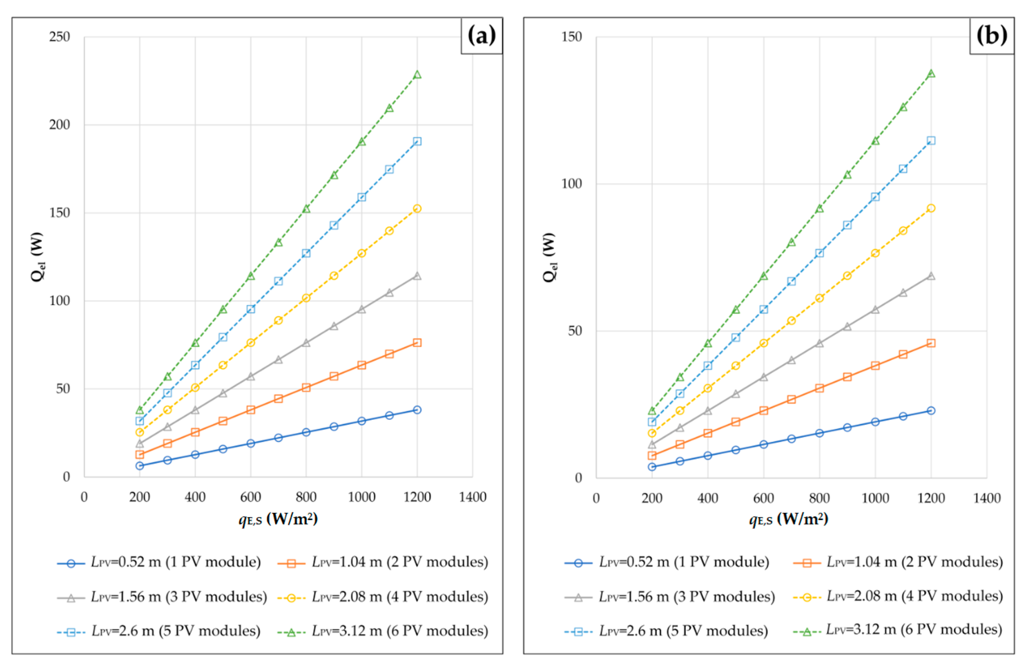
- For the cases where PV sections consist of one and two PV modules, the air flow regimes over the upper surfaces of the PV sections and the appropriate acrylic plates are laminar. In addition, the turbulent flow of air along one ventilation channel corresponds to higher values for the velocity of air at the outlet of the channel and the average temperature of roof- or façade-integrated PV modules. Furthermore, for the cases where PV sections consist of four or more PV modules, the air flow is turbulent at solar irradiance greater than 250 W/m2 or 200 W/m2, respectively. Finally, the use of façade-integrated PV modules in urban areas contributes to the reduction in greenhouse gas emissions, the generation of clean electricity on-site, and the zero carbon transition of cities.
- Future research on this issue should include roof- or façade-integrated PV systems with different ventilation channels, PV sections with seven or more PV modules, and absorbers with larger absorption areas. In addition, future studies should deal with newer PV technologies and include more experiments, as well as appropriate economic and environmental analyses.
Author Contributions
Funding
Institutional Review Board Statement
Informed Consent Statement
Data Availability Statement
Conflicts of Interest
Nomenclature
| Specific heat of air at the film temperature in J/(kg·K) | |
| Specific heat of air at the ambient air temperature in J/(kg·K) | |
| Hydraulic diameter of the channel in m, | |
| View factor | |
| Friction coefficient for flow in a smooth pipe or channel | |
| Acceleration due to gravity, = 9.81 m/s2 | |
| Forced convection heat transfer coefficient between the air in the ventilation channel and the bottom surface of the acrylic plate in W/(m2·K) | |
| Free convection heat transfer coefficient between the upper surface of the acrylic plate and the ambient air in W/(m2·K) | |
| Free convection heat transfer coefficient for the upper surface of the PV section in W/(m2·K) | |
| Radiation heat transfer coefficient for the upper surface of the PV section in W/(m2·K) | |
| Pressure loss coefficient for the inlet of the rectangular channel, 0.5–1.5 | |
| Sum of the pressure loss coefficients and | |
| Pressure loss coefficient for the outlet of the rectangular channel, 1.0–2.4 | |
| Thermal conductivity of air at the film temperature in W/(m·K) | |
| Thermal conductivity of air at the temperature in W/(m·K) | |
| Thermal conductivity of the acrylic plate in W/(m·K), = 0.19 W/(m·K) | |
| Height of the absorber section (or acrylic plate) in m | |
| Height of the bottom section of the ventilation channel in m | |
| Characteristic length of the PV section () or acrylic plate () in m | |
| Height of the PV section in m | |
| Height of the top section of the solar chimney in m | |
| Nusselt number | |
| Prandtl number | |
| Amount of heat absorbed by the mass of the air in the ventilation channel in W | |
| Free convection heat transfer between the upper surface of the PV section and the ambient air in W/m2 | |
| Solar irradiance that can be received by a horizontal surface on Earth in W/m2 | |
| Power related to the generation of electricity in the PV section in W | |
| Heat transfer through the acrylic plate between the air in the ventilation channel and the ambient air in W/m2 | |
| Radiation heat exchange between the upper surface of the PV section and the surroundings in W/m2 | |
| Rayleigh number | |
| Reynolds number, | |
| Area of one side of the acrylic plate in m2 | |
| Cross-sectional area of the ventilation channel in m2 | |
| Area of one side of the PV section in m2 | |
| Temperature of the ambient air in K or °C | |
| Average temperature of the air in the ventilation channel in K or °C | |
| Average temperature of the acrylic plate in K or °C | |
| Temperature of the bottom surface of the acrylic plate in K or °C | |
| Temperature of the upper surface of the acrylic plate in K or °C | |
| Film temperature in K | |
| Temperature of the air at the inlet of the ventilation channel in K or °C | |
| Temperature of the air at the outlet of the ventilation channel in K or °C | |
| Average temperature of the PV section in K or °C | |
| Temperature of the bottom surface of the PV section in K or °C | |
| Temperature of the upper surface of the PV section in K or °C | |
| Temperature of the sky in K or °C | |
| Overall heat transfer coefficient for the acrylic plate in W/(m2·K) | |
| Average velocity of the air in the ventilation channel in m/s, | |
| Air velocity at the inlet of the ventilation channel in m/s | |
| Air velocity at the outlet of the ventilation channel in m/s | |
| Solar absorption coefficient for the absorption area of the absorber | |
| Solar absorption coefficient for the upper surface of the PV section | |
| Thermal diffusivity of air in m2/s, | |
| Thermal expansion coefficient of air in 1/K, | |
| Thickness of the acrylic plate in m, = 0.003 m | |
| Total pressure difference due to buoyancy (natural draft pressure) in kg/(m·s2) | |
| Total pressure drop across the ventilation channel in kg/(m·s2) | |
| Temperature difference between the two surfaces of the PV section in K | |
| Thermal emissivity for the upper surface of the PV section | |
| Efficiency of conversion of solar energy into electricity | |
| Dynamic viscosity of air at the film temperature in kg/(m·s) | |
| Kinematic viscosity of air in m2/s, | |
| Average kinematic viscosity of the air in the channel at the temperature in m2/s | |
| Wetted perimeter of the channel in m, = 0.45 m | |
| Angle of inclination in degrees | |
| Density of air at the film temperature in kg/m3 | |
| Density of air at the ambient air temperature in kg/m3 | |
| Density of air at the temperature in kg/m3 | |
| Stefan–Boltzmann constant, = 5.67 × 10⁻⁸ W/(m2·K4) | |
| Solar transmittance for the acrylic plate |
References
- Seklecki, K.; Litzbarski, L.S.; Adamowicz, M.; Grochowski, J. PV installations and the safety of residential buildings. Inż. Bezpieczeństwa Obiektów Antropog. 2023, 4, 1–10. [Google Scholar] [CrossRef]
- Ghaleb, B.; Asif, M. Application of solar PV in commercial buildings: Utilizability of rooftops. Energy Build. 2022, 257, 111774. [Google Scholar] [CrossRef]
- Hussain, M.N.; Qamar, S.B.; Janajreh, I.; Zamzam, S. Solar PV implementation in industrial buildings: Economic study. In Proceedings of the 2017 International Renewable and Sustainable Energy Conference (IRSEC), Tangier, Morocco, 4–7 December 2017; pp. 1–5. [Google Scholar] [CrossRef]
- Gholami, H. Technical potential of solar energy in buildings across Norway: Capacity and demand. Sol. Energy 2024, 278, 112758. [Google Scholar] [CrossRef]
- Han, Z.; Zhou, W.; Sha, A.; Hu, L.; Wei, R. Assessing the photovoltaic power generation potential of highway slopes. Sustainability 2023, 15, 12159. [Google Scholar] [CrossRef]
- Dai, Y.; Yin, Y.; Lu, Y. Strategies to facilitate photovoltaic applications in road structures for energy harvesting. Energies 2021, 14, 7097. [Google Scholar] [CrossRef]
- Klimenta, D.; Minić, D.; Pantić-Ranđelović, L.; Radonjić-Mitić, I.; Premović-Zečević, M. Modeling of steady-state heat transfer through various photovoltaic floor laminates. Appl. Therm. Eng. 2023, 229, 120589. [Google Scholar] [CrossRef]
- Alawasa, K.M.; AlAbri, R.S.; Al-Hinai, A.S.; Albadi, M.H.; Al-Badi, A.H. Experimental study on the effect of dust deposition on a car park photovoltaic system with different cleaning cycles. Sustainability 2021, 13, 7636. [Google Scholar] [CrossRef]
- Fu, Y.; Xu, W.; Wang, Z.; Zhang, S.; Chen, X.; Wang, B. Parametric study and sensitivity analysis on thermoelectric energy generation of building integrated photovoltaic facades in various climatic zones of China. J. Build. Eng. 2024, 82, 108096. [Google Scholar] [CrossRef]
- Chatzipanagi, A.; Frontini, F.; Virtuani, A. BIPV-temp: A demonstrative building integrated photovoltaic installation. Appl. Energy 2016, 173, 1–12. [Google Scholar] [CrossRef]
- Martín-Chivelet, N.; Gutiérrez, J.C.; Alonso-Abella, M.; Chenlo, F.; Cuenca, J. Building retrofit with photovoltaics: Construction and performance of a BIPV ventilated façade. Energies 2018, 11, 1719. [Google Scholar] [CrossRef]
- Fu, Y.; Xu, W.; Wang, Z.; Zhang, S.; Chen, X.; Chu, J. Experimental investigation on thermal characteristics and novel thermal estimation method of BIPV façade air channel under actual operation. J. Build. Eng. 2023, 72, 106489. [Google Scholar] [CrossRef]
- Rahiminejad, M.; Khovalyg, D. Numerical and experimental study of the dynamic thermal resistance of ventilated air-spaces behind passive and active façades. Build. Environ. 2022, 225, 109616. [Google Scholar] [CrossRef]
- Hassan, A.M. Solar chimney performance driven air ventilation promotion: An investigation of various configuration parameters. Buildings 2023, 13, 2796. [Google Scholar] [CrossRef]
- Zheng, Y.; Miao, J.; Yu, H.; Liu, F.; Cai, Q. Thermal analysis of air-cooled channels of different sizes in naturally ventilated photovoltaic wall panels. Buildings 2023, 13, 3002. [Google Scholar] [CrossRef]
- Li, K.; Zhou, Y.; Wei, D.; Jin, X. An investigation of the electrical and thermal performances of the photovoltaic wall with different air gap thicknesses and modes in winter. Build. Serv. Eng. Res. Technol. 2023, 44, 605–624. [Google Scholar] [CrossRef]
- Moghaddam, H.A.; Tkachenko, S.; Yeoh, G.H.; Timchenko, V. A newly designed BIPV system with enhanced passive cooling and ventilation. Build. Simul. 2023, 16, 2093–2107. [Google Scholar] [CrossRef]
- Zhang, H.; Luo, C.; Li, W.; Chen, X.; Luo, Q.; Yu, Y.; Su, X.; Peng, R. Performance prediction of ventilated building-integrated photovoltaic system with lightweight flexible crystalline silicon module based on experimental fitting method. Renew. Energy 2024, 234, 121262. [Google Scholar] [CrossRef]
- Rai, P.; Chowdhury, A. Experimental study of the solar chimney effect in naturally ventilated BIPV cladding system under real operating condition. Sol. Energy 2024, 278, 112769. [Google Scholar] [CrossRef]
- Karimi-Pour-Fard, P.; Beheshti, H.; Baniasadi, E. Energy and exergy analyses of a solar chimney power plant with thermal energy storage. Int. J. Exergy 2016, 20, 150–169. [Google Scholar] [CrossRef]
- Karimipour-Fard, P.; Beheshti, H. Performance enhancement and environmental impact analysis of a solar chimney power plant: Twenty-four-hour simulation in the climate condition of Isfahan Province, Iran. Int. J. Eng. Trans. B Appl. 2017, 30, 1260–1269. [Google Scholar] [CrossRef]
- Saleh, M.J.; Atallah, F.S.; Algburi, S.; Ahmed, O.K. Enhancement methods of the performance of a solar chimney power plant: Review. Results Eng. 2023, 19, 101375. [Google Scholar] [CrossRef]
- Gao, N.; Yan, Y.; Sun, R.; Lei, Y. Natural ventilation enhancement of a roof solar chimney with wind-induced channel. Energies 2022, 15, 6492. [Google Scholar] [CrossRef]
- Azhar, M.H.A.; Alhammadi, S.; Jang, S.; Kim, J.; Kim, J.; Kim, W.K. Long-term field observation of the power generation and system temperature of a roof-integrated photovoltaic system in South Korea. Sustainability 2023, 15, 9493. [Google Scholar] [CrossRef]
- Nguyen, Y.Q.; Huynh, T.N. Evaluating the performance of a combined vertical wall–horizontal roof solar chimney for the natural ventilation of buildings. Buildings 2024, 14, 1501. [Google Scholar] [CrossRef]
- Rodriguez Miranda, S.; Gamboa, G.O.; Zamora-Antuñano, M.A.; Farrera-Vázquez, N.; García-García, R. CFD evaluation of thermal conditioning in a house of social interest with a solar chimney arrangement in Guanajuato, Mexico. Processes 2023, 11, 1286. [Google Scholar] [CrossRef]
- Kim, Y.-S.; Kim, A.-R.; Tark, S.-J. Building-integrated photovoltaic modules using additive-manufactured optical pattern. Energies 2022, 15, 1288. [Google Scholar] [CrossRef]
- Martín-Chivelet, N.; Polo, J.; Sanz-Saiz, C.; Núñez Benítez, L.T.; Alonso-Abella, M.; Cuenca, J. Assessment of PV module temperature models for building-integrated photovoltaics (BIPV). Sustainability 2022, 14, 1500. [Google Scholar] [CrossRef]
- Li, J.; Cai, Q.; Wang, X.; Liu, F.; Yu, H.; Liu, J.; Miao, J.; Li, G.; Chen, T.; Feng, L.; et al. Performance study of ventilated energy-productive wall: Experimental and numerical analysis. Sol. Energy 2024, 273, 112512. [Google Scholar] [CrossRef]
- Zhang, X.; Miao, J.; Geng, Z.; Zhang, S.; Feng, F.; Cao, A.; Wang, L.; Wei, W.; He, S.; Gao, M. Investigation on the operation performance of solar panels cooled by a natural draft cooling system. Therm. Sci. Eng. Prog. 2024, 54, 102799. [Google Scholar] [CrossRef]
- Babin, M.; Andersen, N.L.; Thorning, J.K.; Thorsteinsson, S. Yield analysis of a BIPV façade prototype installation. Energy Build. 2024, 322, 114730. [Google Scholar] [CrossRef]
- Zhang, T.; Wang, M.; Yang, H. A review of the energy performance and life-cycle assessment of building-integrated photovoltaic (BIPV) systems. Energies 2018, 11, 3157. [Google Scholar] [CrossRef]
- Rehman, S.; Aliyu, K.N.; Alhems, L.M.; Mohandes, M.A.; Himri, Y.; Allouhi, A.; Alam, M.M. A comprehensive global review of building integrated photovoltaic systems. FME Trans. 2021, 49, 253–268. [Google Scholar] [CrossRef]
- Pillai, D.S.; Shabunko, V.; Krishna, A. A comprehensive review on building integrated photovoltaic systems: Emphasis to technological advancements, outdoor testing, and predictive maintenance. Renew. Sustain. Energy Rev. 2022, 156, 111946. [Google Scholar] [CrossRef]
- Chen, L.; Baghoolizadeh, M.; Basem, A.; Ali, S.H.; Ruhani, B.; Sultan, A.J.; Salahshour, S.; Alizadeh, A.A. A comprehensive review of a building-integrated photovoltaic system (BIPV). Int. Commun. Heat Mass Transf. 2024, 159, 108056. [Google Scholar] [CrossRef]
- Klimenta, D.; Perović, B.; Klimenta, J.; Jevtić, M. Passive cooling of PV panels: The case of PV panels and solar chimney integrated in the roof of a family house. In Proceedings of the 2014 13th International Symposium INFOTEH-JAHORINA, Jahorina, RS, Bosnia and Herzegovina, 19–21 March 2014; pp. 281–286. [Google Scholar]
- Arpaci, V.S.; Selamet, A.; Kao, S.H. Introduction to Heat Transfer, 1st ed.; Prentice-Hall Inc.: Upper Saddle River, NJ, USA, 2000; pp. 288–330. [Google Scholar]
- Agathokleous, R.A.; Kalogirou, S.A. Part I: Thermal analysis of naturally ventilated BIPV system: Experimental investigation and convective heat transfer coefficients estimation. Sol. Energy 2018, 169, 673–681. [Google Scholar] [CrossRef]
- Date, A.; Singh, R.; Date, A.; Akbarzadeh, A. Cooling of solar cells by chimney-induced natural draft of air. In Proceedings of the 48th AuSES Annual Conference (Solar2010), Canberra, ACT, Australia, 1–3 December 2010; pp. 1–11. [Google Scholar]
- Fujii, T.; Imura, H. Natural-convection heat transfer from a plate with arbitrary inclination. Int. J. Heat Mass Transf. 1972, 15, 755–767. [Google Scholar] [CrossRef]
- Holman, J.P. Heat Transfer, 8th ed.; McGraw-Hill Inc.: New York, NY, USA, 1999. [Google Scholar]
- Bergman, T.L.; Lavine, A.S.; Incropera, F.P.; Dewitt, D.P. Fundamentals of Heat and Mass Transfer, 7th ed.; John Wiley & Sons, Inc.: Hoboken, NJ, USA, 2011. [Google Scholar]
- Sakonidou, E.P.; Karapantsios, T.D.; Balouktsis, A.I.; Chassapis, D. Modeling of the optimum tilt of a solar chimney for maximum air flow. Sol. Energy 2008, 82, 80–94. [Google Scholar] [CrossRef]
- Dai, Y.J.; Sumathy, K.; Wang, R.Z.; Li, Y.G. Enhancement of natural ventilation in a solar house with a solar chimney and a solid adsorption cooling cavity. Sol. Energy 2003, 74, 65–75. [Google Scholar] [CrossRef]
- Solar Electric Supply, Inc. Available online: https://www.solarelectricsupply.com/bp-solar-bpsx320?srsltid=AfmBOorsrcvmQkz_QvLkV2IKY9LltAqJ8BQiZluMA_a6D_m1v_L1MGXP (accessed on 29 January 2025).

| Parameter | Unit | Simulation | |
|---|---|---|---|
| First | Second | ||
| Degrees | 37 | 90 | |
| °C | 44.03 | 34.3 | |
| °C | 33.01 | 28.15 | |
| m/s | 0.498 | 0.524 | |
| m/s | 0.535 | 0.545 | |
| m/s | 0.517 | 0.534 | |
| W | 226.98 | 136.6 1 | |
| W | 191.65 | 115.34 2 | |
| W | 342.8 | 201.05 | |
| W | 3.803 | 2.031 | |
| W | 17.069 | 12.23 | |
| W | 32.067 | 25.42 | |
| W | 31.777 | 19.124 | |
| W/(m2·K) | 2.885 | 2.972 | |
| W/(m2·K) | 3.172 | 2.805 | |
| °C | 27.25 | 25.16 | |
| W/(m2·K) | 3.17 | 2.805 | |
| W/(m2·K) | 12.444 | 17.66 | |
| °C | 43.49 | 39.72 | |
| – | 1.3257 × 10⁸ | 7.9744 × 10⁷ | |
Disclaimer/Publisher’s Note: The statements, opinions and data contained in all publications are solely those of the individual author(s) and contributor(s) and not of MDPI and/or the editor(s). MDPI and/or the editor(s) disclaim responsibility for any injury to people or property resulting from any ideas, methods, instructions or products referred to in the content. |
© 2025 by the authors. Licensee MDPI, Basel, Switzerland. This article is an open access article distributed under the terms and conditions of the Creative Commons Attribution (CC BY) license (https://creativecommons.org/licenses/by/4.0/).
Share and Cite
Šućurović, M.; Klimenta, D.; Andriukaitis, D.; Žilys, M.; Sledevič, T.; Tomović, M. An Analytical Model for the Steady-State Thermal Analysis of Façade-Integrated PV Modules Cooled by a Solar Chimney. Appl. Sci. 2025, 15, 1664. https://doi.org/10.3390/app15031664
Šućurović M, Klimenta D, Andriukaitis D, Žilys M, Sledevič T, Tomović M. An Analytical Model for the Steady-State Thermal Analysis of Façade-Integrated PV Modules Cooled by a Solar Chimney. Applied Sciences. 2025; 15(3):1664. https://doi.org/10.3390/app15031664
Chicago/Turabian StyleŠućurović, Marko, Dardan Klimenta, Darius Andriukaitis, Mindaugas Žilys, Tomyslav Sledevič, and Milan Tomović. 2025. "An Analytical Model for the Steady-State Thermal Analysis of Façade-Integrated PV Modules Cooled by a Solar Chimney" Applied Sciences 15, no. 3: 1664. https://doi.org/10.3390/app15031664
APA StyleŠućurović, M., Klimenta, D., Andriukaitis, D., Žilys, M., Sledevič, T., & Tomović, M. (2025). An Analytical Model for the Steady-State Thermal Analysis of Façade-Integrated PV Modules Cooled by a Solar Chimney. Applied Sciences, 15(3), 1664. https://doi.org/10.3390/app15031664