1. Introduction
Unmanned aerial vehicle (UAV) launch systems, such as catapult mechanisms, require lightweight yet solid structures. The main load-bearing part of a catapult is exposed to high thrust forces. If the part is designed too conservatively and uses excessive material, its weight increases unnecessarily. This added weight can reduce the overall efficiency of the system. This strongly incentivizes the optimization of the weight of mechanical components in order to improve transportability and performance without compromising safety or durability [
1]. The launch trolley, which carries the aircraft, is critical for stability and the life cycle, and has high mechanical performance requirements. Designs that are excessively strong for these components, which are subject to sudden thrust forces, negatively impact the structure’s weight and reduce its efficiency.
An effective way to reduce weight while maintaining structural strength is through Topology Optimization (TO), a method widely used in mechanical and aerospace engineering to design lightweight yet durable components [
2,
3]. TO is a numerical technique that aims to achieve the best structural performance with the least amount of material. It does this by optimizing how material is distributed within a given design space. Although the basic idea was introduced in the early 20th century, modern computational applications began to emerge in the late 1980s. The method became well-established with the pioneering work of Bendsoe and Kikuchi, who introduced a continuous material distribution approach [
4]. The main purpose of TO is to find the most effective way to place material within a given design space. The goal is usually to make the structure as stiff as possible or to reduce deformation energy. While doing this, certain limits—such as the allowed volume or mass—must be respected. During optimization, material is systematically removed from low-stress regions and concentrated in areas that carry higher loads or experience greater deformation. As a result, the optimized structure often takes on innovative, lightweight forms, such as thin load paths or lattice-like geometries that would be difficult to imagine using traditional design intuition. A key advantage of TO over conventional design methods is its ability to automatically generate efficient and high-performance shapes, making it a powerful tool for achieving weight reduction and stiffness improvement in modern engineering applications.
Among the TO methods, Solid Isotropic Material with Penalization (SIMP) [
4], Evolutionary Structural Optimization (ESO) [
5], Bidirectional Evolutionary Structural Optimization (BESO) [
6], and level-set approaches [
7] are prominent. Bendsoe and Kikuchi [
4] laid the theoretical foundation of the method by developing the material distribution-based optimization approach with the concept of “continuous density”. Subsequently, the Evolutionary Structural Optimization (ESO) method was proposed by Xie and Steven [
5], thus introducing an intuitive element removal approach to structural optimization problems. However, a limitation of classical ESO is the inability to add back the removed material, and therefore, the optimization process proceeds in a one-way (irreversible) manner. This problem was overcome by the BESO algorithm developed by Huang and Xie [
6]. BESO reduces the risk of the optimization getting stuck in local solutions by refilling regions removed in previous steps with material when necessary and ensures convergence of the solution. In subsequent years, with the contributions of Rozvany and other researchers, the TO method has matured considerably, and not only continuous density and evolutionary methods but also different approaches such as level-set and topological derivatives have been introduced in the literature [
8,
9,
10,
11,
12]. However, due to their solid theoretical basis and ease of implementation, the most widely used methods in industrial applications today are the density-based SIMP technique and evolutionary techniques such as ESO/BESO. Nowadays, intensive research is being carried out in the current literature on improving existing algorithms or developing new hybrid methods to increase the effectiveness of TO methods, and studies in this field continue unabated [
13,
14,
15,
16,
17].
Numerous studies have been published in the literature comparing SIMP and BESO methods or applying them to practical design problems. These studies examine which method offers which advantages for different geometries and loading conditions and identify method-specific performance criteria. For example, Yago et al. conducted an extensive comparative study testing SIMP, BESO, level set, and several other methods on three-dimensional industrial-scale samples [
18]. The results showed that both SIMP and BESO can produce high-quality designs in practice, but they exhibit different scaling behaviors in terms of computational time as the problem size increases [
18].
In recent years, examples of the application of SIMP and BESO to specific engineering problems have also been extensive in the literature. Structural elements and brackets, in particular, have become popular test cases for demonstrating the effectiveness of these methods [
19]. As one such example, Zhuang and Zeng achieved a 47.1% weight reduction in an automotive subframe using SIMP-based optimization, demonstrating that the design successfully met structural and dynamic requirements [
20]. Similarly, various aerospace applications are also being redesigned using TO. Crespo-Sanchez et al. investigated the TO design of an aircraft turbofan engine air intake component manufactured using SLM on various materials and demonstrated that it achieved a weight reduction of up to 71% compared to the conventional design while maintaining structural integrity [
21]. Consistent with these findings, significant reductions in mass and residual stresses were reported for aircraft brackets manufactured using additive manufacturing using SIMP-based TO, with a 50–75% volume reduction [
22]. The SI-ESO method, developed to address the iteration oscillation and mesh deviation issues in the conventional ESO method, was applied to the aerospace generator rear cover and validated through additive manufacturing. This resulted in a 31% weight reduction, as well as higher stiffness and frequency performance [
23]. Similarly, the Abaqus-Matlab collaborative framework, developed to increase the industrial applicability of the BESO method, increased the computational efficiency and accuracy of TO in complex engineering structures, and a 31% volume reduction was achieved in validation examples and a practical application [
24].
In recent years, TO methods have been successfully applied in many studies aiming to establish a balance between lightweight and strength in both the automotive and aerospace fields [
19,
20,
21]. Comparisons between SIMP and BESO methods have revealed the advantages and limitations of both approaches under different problem sizes and loading conditions [
18]. However, a review of the existing literature reveals that most studies either focus on a single method or have tested the methods separately on different example problems. This indicates that studies specifically involving direct comparative applications of SIMP and ESO/BESO methods on the same engineering component remain relatively limited. Moreover, although there are studies focusing on current trends such as integration with additive manufacturing, incorporating multi-physics design criteria, and improving the computational efficiency of methods [
13,
14,
16], the joint evaluation of different optimization algorithms in real engineering problems remains a significant research gap. Therefore, this gap in the literature clearly demonstrates the need for studies demonstrating the comparative effectiveness of methods.
This study addresses the TO of a launch trolley for an UAV catapult mechanism, which is critical for aerospace applications. The study’s originality lies in the comparative evaluation of the results of both SIMP and ESO/BESO algorithms applied to the same engineering component. Analyses were conducted using the SIMP algorithm integrated into Abaqus Tosca software and ESO/BESO-based approaches, comparing the performance of the methods in terms of weight reduction, structural strength, ease of manufacture, and compatibility with additive manufacturing. In this context, the study not only demonstrates the practical applicability of the methods but also provides guidance for designers in mechanical and aerospace engineering regarding which approach is more suitable under which circumstances.
2. Topology Optimization Algorithms
In optimization problems, defining the “best structure” depends on the optimization objective. For structural optimization, this is the objective function, a mathematical expression that can be maximized or minimized to quantify a structure’s performance. These functions represent measurable units such as the weight of the members, the stiffness of the structure, the overall cost, and the susceptibility to a specific failure mode like buckling. Therefore, determining the variables of the mathematical model, such as the number of variables defining the size of the mathematical model, the number of possible solutions, and, consequently, the computational cost required for the analysis, is critical. Another important factor in optimization is the application of constraints. While not a requirement, these constraints can be crucial for the search space, computational cost, and process efficiency. Constraints are pre-selected values that remain constant throughout the optimization procedure and restrict the search space (i.e., volume, cross-section, stresses, etc.). TO, thanks to its ability to generate unique structures by varying their size and shape in the design space, can be integrated with other types of optimization, making it one of the most preferred procedures. Due to this feature, various computational strategies, especially density-based methods and evolutionary techniques, have been developed and are widely applied in the literature.
2.1. Solid Isotropic Material with Penalization (SIMP)
The SIMP method is a frequently used TO strategy based on maximizing structural stiffness under volume constraints. SIMP offers a mathematically efficient and stable formulation that is well-suited to structural compliance problems, particularly when the goal is to maximize stiffness under specified loads [
23]. This approach aims to increase the stiffness of the structure by minimizing compliance under specified load conditions. In SIMP, each finite element is defined as a density variable that can vary continuously in the range
. Initially, the entire design domain is assumed to be filled with material, and the material distribution in the structure is optimized over this continuous density field [
21]. A penalty coefficient (
) is used in the SIMP method to make the resulting interpolated (grayscale) solutions practically manufacturable. This penalty forces the density variable (
) to extreme values of 0 or 1, ultimately converging the design to a two-state structure: either fully material or empty [
24]. Regions with
indicate the presence of material, while regions with
are areas devoid of material [
25]. Choosing a
value that is too low or too high can lead to excessive grayscale or very rapid convergence to local minima; therefore, good convergence to 0–1 solutions can be achieved by setting
[
18,
26].
The core logic of SIMP-based TO is defined as an interconnected flow in Equations (1)–(6). Equation (1) defines the effective modulus of elasticity (
) for each element based on its density value
. This determines the elastic behavior of the material depending on its density. Here,
represents the effective modulus of elasticity of the ith element,
represents the modulus of elasticity of the fully filled material, and
is a very small value assigned to empty elements to ensure numerical stability.
is the relative density variable of the element and varies in the range
.
is the penalty coefficient, and
is generally chosen to suppress gray areas and allow densities to converge to 0 or 1. Equation (2) uses this elasticity modulus to generate the element’s elasticity matrix
, thus updating the stress–strain relationships based on density. Here,
is the Poisson’s ratio. The elasticity matrix and the element’s geometric properties are converted to the element stiffness matrix
using Equation (3). This matrix defines the stress–strain relationship, taking into account the isotropic properties of the material. Here,
represents the strain-displacement matrix derived from the element’s shape functions, and
represents the volume of the
ith element.
Equation (4) calculates the global stiffness matrix (
) of the structure by combining all element stiffness matrices through the assembly process. Here, A is the assembly matrix, and the overall stiffness matrix of the structure is created by combining the stiffness matrices of all elements.
represents the total number of elements. Equation (5) calculates the displacement vector (
). Here,
is the external force vector. Equation (6) is used to calculate compliance (
). Minimizing this value, i.e., reducing the deformation energy, means maximizing the total stiffness of the structure. In this way, the process begins with density variables (Equations (1) and (2)), generates stiffness at the element and global levels (Equations (3) and (4)), resolves the deformation with equilibrium (Equation (5)), and finally defines the optimization target by calculating the compliance value (Equation (6)). This interconnected loop forms the core of the SIMP optimization algorithm.
Theoretically, SIMP solves an optimization problem defined in a continuous design variable space using gradient-based methods (e.g., the Optimality Criteria Algorithm or Mathematical Programming Techniques). In this respect, the SIMP method exhibits robust convergence behavior, and when combined with appropriate filtering techniques, regular (checkerboard-free) and stable designs can be achieved [
21]. Indeed, the SIMP approach is preferred in the literature due to its mathematical efficiency and numerical stability in problems such as structural compliance minimization [
27,
28,
29], and it is built into many commercial software programs (e.g., Autodesk Fusion 360, SolidWorks Simulation, Siemens NX). Another advantage of the SIMP method is its wide acceptance and well-understood nature in engineering applications, which makes the results relatively easy to interpret and verify. However, after the optimized design obtained with SIMP, subsequent thresholding or design refinement may be required to completely remove gray areas. This process may lead to minor design changes, which may slightly deviate the structural performance from the optimal solution. Therefore, SIMP optimization results are typically verified through FEA, with minor manual adjustments made as needed.
2.2. Evolutionary Structural Optimization/Bi-Directional ESO (ESO/BESO)
ESO proposed by Xie and Steven, is a heuristic TO method that improves the design by gradually removing material from regions with low strain energy [
5]. The primary goal of ESO is to maximize stiffness by minimizing the structural compliance within a given volume constraint. In the ESO method, the lowest-contribution elements are removed from the structure as a hard-kill method at each iteration, based on performance criteria such as stress, within a specified volume reduction ratio [
30]. This process is repeated until the optimization objective (e.g., stiffness maximization) is improved or a predetermined volume ratio requirement is met. The ESO method offers an intuitively simple and relatively easy-to-implement approach, as the worst-performing material is discarded at each step to improve the structure’s performance. In the classical ESO method, the optimization process is unidirectional because the removed material cannot be replaced, which can lead to the design getting stuck in a local optimum. To overcome this problem, the BESO algorithm developed by Huang and Xie [
6] not only removes inefficient elements at each iteration but also updates the topology bidirectionally by refilling some regions removed in previous steps with material. Thus, BESO reduces the risk of the optimization getting stuck in local solutions and exhibits a more stable convergence behavior, resulting in more balanced topologies [
31].
This bidirectional optimization process allows the structure to offer a more balanced and performance-oriented topology through both material reduction and repositioned material addition. In engineering applications, it offers more favorable transitions than the monolithic “remove-and-wait” approach: Optimal truss-like skeletal systems emerge within the anatomical order, and structural stiffness and strength are maintained or improved while targeting the design volume. Such an optimization problem, aimed at volumetric minimization, is expressed by Equation (7) [
6].
Here,
represents the applied external force vector, and
represents the displacement vector resulting from these forces. The
value, known as compliance, measures the total deformation energy dissipated under the load applied to the structure. The total structural volume or volume fraction determined as the target in the optimization process is
(Equation (8)). The total number of elements in the system is expressed as
. The binary density variable
, used as the design variable, represents the absence (0) or presence (1) of the relevant element (Equation (9)). In this context, the change in the average compliance or total strain energy observed when the ith solid element is removed from a structure is explained by the strain energy of the element itself (Equation (10)), which is also referred to as the elemental sensitivity number.
Here,
is the nodal displacement vector of the ith element, and
is the stiffness matrix of the element. This basic sensitivity value is calculated by averaging the nodal sensitivities of each element (Equation (11)) [
6].
Here,
represents the total number of elements connected to node
. Transferring nodal sensitivities to the element level is a process that must be performed before determining the topology. In this process, a subregion (
) of radius rmin is defined around each element center. Nodes in this region are evaluated with a distance-dependent weight function
, and the filtered sensitivity of the element is calculated using Equation (12):
This equation smooths element sensitivities by accounting for surrounding nodal effects, resulting in more stable mesh-independent results. Filtering also reduces instabilities in the optimization process by transferring sensitivity to void elements.
Compared to classical ESO, BESO’s features of higher computational efficiency, mesh-independence, and more reliable convergence are prominent [
32]. Especially in engineering applications, BESO’s ability to increase topological variability with this two-way approach is important: the ability to add material in critical regions goes beyond completely removing unnecessary material, producing more stable and performant structures. Indeed, modern research has developed parallel BESO methods (Parallel BESO) for high-resolution TO problems, improving their performance by employing evolutionary rate control, reanalysis techniques, and flexible “hard-kill/soft-kill” strategies [
24]. This enhanced flexibility offered by BESO in terms of structure stability, iteration stability, and manufacturability are key factors in favoring the BESO method. Furthermore, the BESO algorithm’s ability to produce convergent and mesh-independent solutions has made it a widespread design tool thanks to its computational efficiency and robustness.
3. Materials and Methods
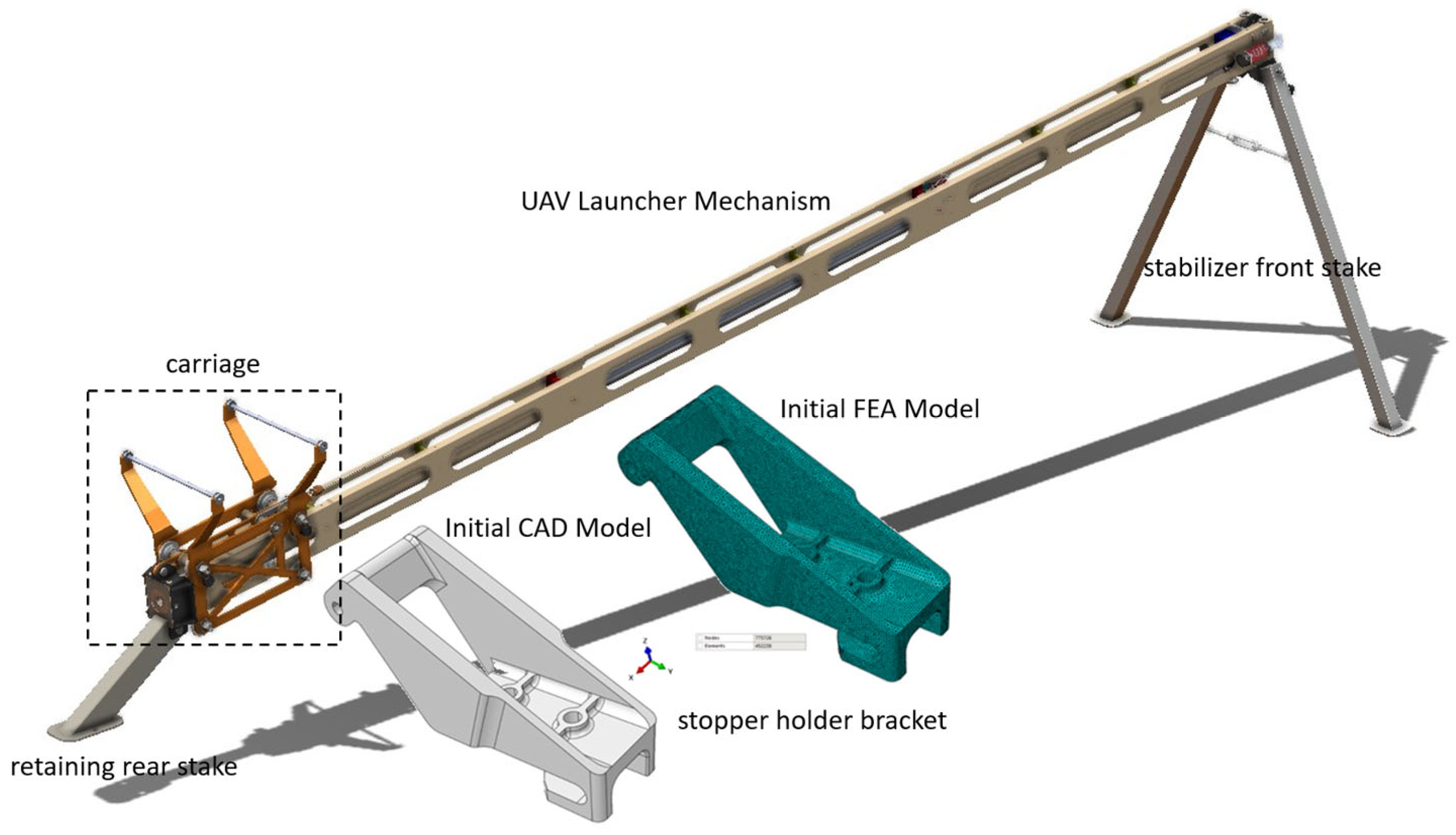
This study systematically investigates the design and optimisation process of a launcher trolley bracket positioned on an UAV catapult used in the aerospace industry (
Figure 1). The analyzed launcher trolley bracket connects the trolley to the catapult rail and experiences the highest compressive and bending stresses during launch. The methodology employed encompasses the design, analysis, optimisation and validation steps aimed at reducing mass while improving the component’s mechanical performance (
Figure 2). In the initial phase, the non-optimised launcher trolley bracket geometry was modelled in Catia (V5R2018), and its geometric consistency was verified. The initial model was subjected to static analysis in the Abaqus 2018 FEA environment to serve as a reference for the structural behaviour. Validation was performed using different mesh densities and solution methods. The analysis results were evaluated to define the structure’s initial force-displacement characteristics and form the basis for the optimization process.
Then, a comparative analysis was conducted on the efficacy of two TO algorithms (SIMP and BESO) utilising FEA results obtained from the initial model. The objective of the optimisation process was to maximise stiffness within the specified volume constraints, whilst simultaneously preserving the functional integrity of the component by limiting geometry changes. The structural performance (compliance, stress, and displacement) of each iteration was evaluated, and the model with the lowest compliance value and balanced constraint functions was selected as the final design. In this process, the ABAQUS-TOSCA was utilised for the SIMP method, and the Abaqus (2018)—Matlab (2024B) integration was employed for the BESO method. The resulting optimisation outputs were then compared to ascertain the most suitable topology.
To ensure numerical stability and convergence, both SIMP and BESO algorithms were executed with adaptive filtering and tolerance-based stopping criteria. In the SIMP approach, the Optimality Criteria (OC) method was employed, where convergence was achieved when the compliance variation between two successive iterations was less than 0.01%. For the BESO algorithm, the average strain energy change between iterations was monitored, and optimization was terminated when the difference dropped below 0.05%. In addition, a minimum element density threshold of 0.001 was applied to prevent singularities.
Abaqus-Matlab integration was realized using a Python-based data exchange script, which automatically transferred element sensitivity, stress, and displacement results in .txt format between iterations. This direct coupling eliminated redundant read/write operations, improving computational efficiency by approximately 20%. All optimizations were executed on an Intel i7-10510U (1.8 GHz, 16 GB RAM) workstation. These convergence and stability controls ensured mesh-independent, repeatable, and computationally efficient results for both optimization strategies.
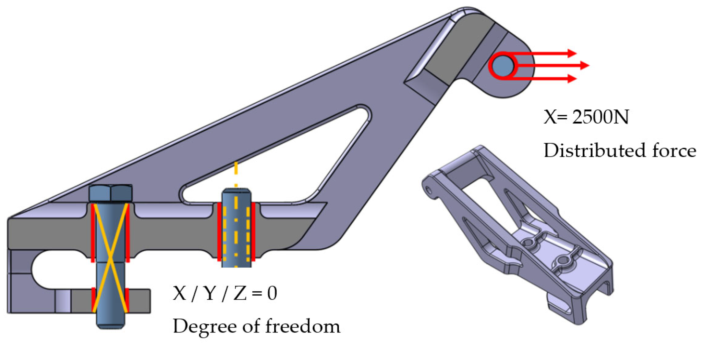
Before the optimization, the structural analysis results of the non-optimized initial model must be obtained. For this purpose, boundary conditions must be prepared appropriately for the test environment (
Figure 3). An examination of the part’s design structure reveals a symmetric geometry. Taking advantage of this feature, FEM of half the part was created to minimize time and processor requirements. The loads on the part were applied similarly at a ½ ratio. Because the highest stress and displacement values on the non-optimized geometry were taken as reference, it was determined that a linear material model could be used. Therefore, only the density and yield stress of the AA7075 aluminum alloy were used in the FEA process, ignoring the material’s nonlinear properties.
The material properties of the launch trolley bracket manufactured from 7075 aluminum alloy are given in
Table 1. The FEA mesh models are shown in
Figure 4. The designed model was recreated in the FEM structure in the Abaqus environment. The mesh size of the solution mesh model was set to 2 mm, and the mesh and nodes are shown in
Table 2. Linear static analyses were performed.
To ensure the reliability of the analysis results and to accurately capture complex geometric details, high-density, uniformly distributed, four nodes tetrahedral elements (C3D4) were used throughout the model for SIMP. A review of the literature reveals that regular lattice structures yield more stable results and that it is easier to iteratively add or remove elements from the design region depending on whether the material is present or absent [
33].
In the 3D BESO method, eight nodes hexahedral elements (C3D8), which are widely used, were selected. A review of the literature reveals that regular lattice structures yield more stable results and that it is easier to iteratively add or remove elements from the design region depending on the presence or absence of material [
34].
The prepared mesh was created using Abaqus-Tosca FEM with 187,863 nodes and 86,119 elements, and Abaqus-Matlab FEM with 38,010 nodes and 7366 elements (
Table 1). The nature and density of the elements established an optimal balance between computational efficiency and analytical accuracy, ensuring reliable results that meet engineering requirements. These mesh structures allow for high-resolution analysis of stress and deformation distributions in all critical regions of the analyzed component.
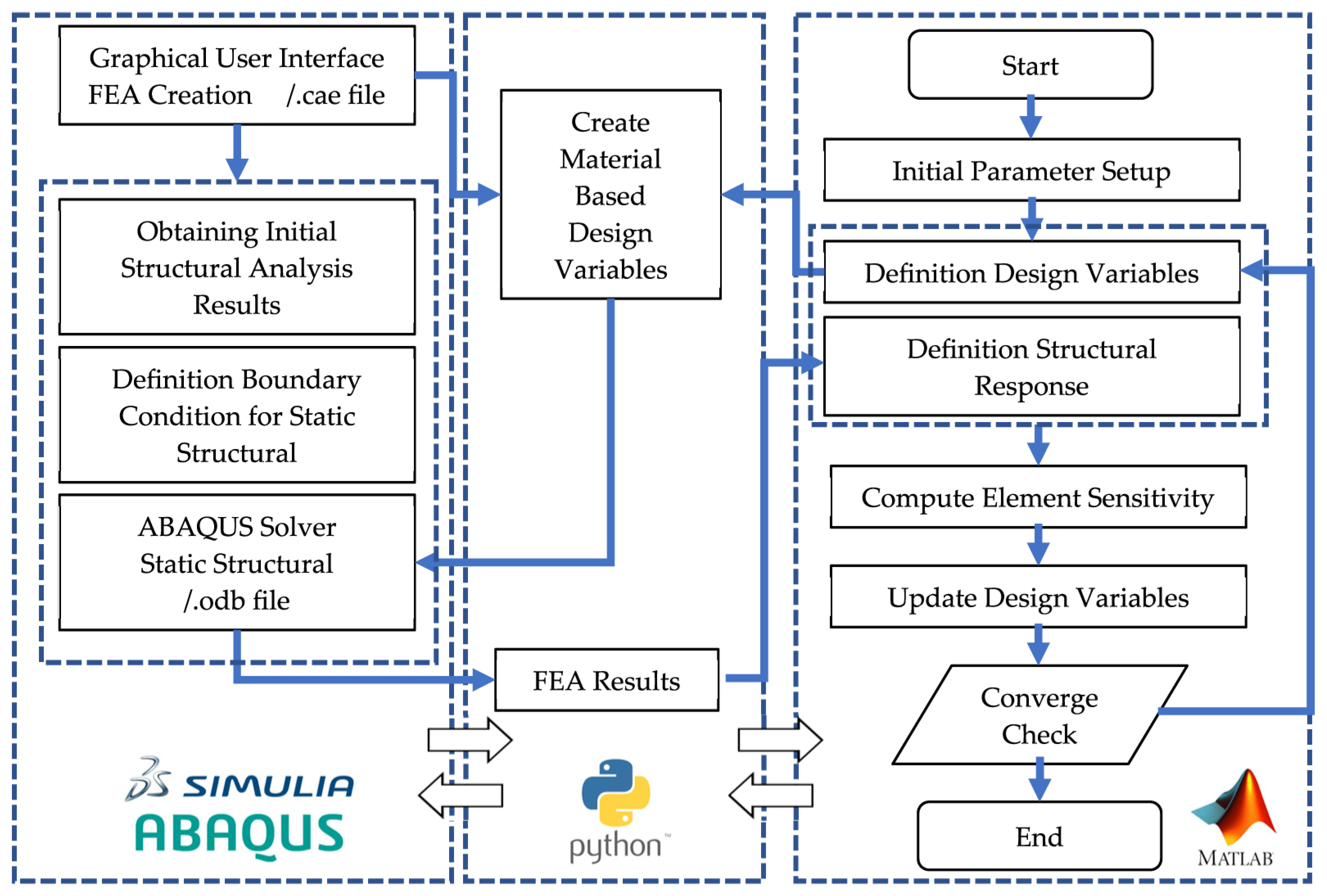
The proposed workflow begins by opening the .cae file (which consists of the geometry, material, boundary conditions, contacts, loads, and mesh model of the initial model without optimization) in Python using the Abaqus Scripting Interface (ASI) (
Figure 5). This way, the parameters required for TO are exported with a .txt extension and read in Matlab.
At the beginning of the process, Matlab performs the initial configuration by matching design variables with element IDs. As an initial condition for the BESO method, all design variables are assigned unit values, and this data is stored in the .txt file format. Then, Matlab runs the ABAQUS Solver using the pre-prepared Python script [
34]. The script accesses the .cae file, extracts part and node information, and then reads the design variables stored in the data file. Elements are classified according to their respective density values, and material properties are updated based on this classification. This allows the model parameters required for FEA to be transferred to the ABAQUS Solver. After the analysis is complete, the script extracts element-level results (stress, displacement, etc.) from the .odb file.
This data is saved in a new .txt format and imported back into the Matlab environment. Based on the resulting outputs, Matlab iterates through the optimization process: sensitivity calculation, sensitivity filtering, updating design variables, and checking convergence. If the convergence criteria are not met, the updated design variables are rewritten to the data file, and the process continues with a new iteration. This interplay cycle repeats until the optimization convergence conditions are met. With this method, the Matlab-based BESO algorithm is directly fed with FEA results, systematically advancing the optimization process (
Figure 5).
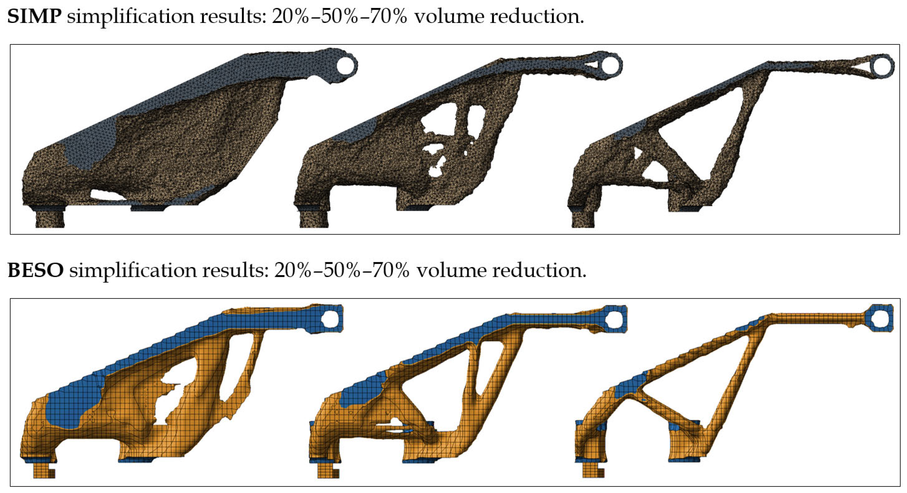
In this study, the values 20%, 50%, and 70% refer to the amount of reduction from the initial solid volume after each optimization process. For example, volume ratio of 50% means that half of the initial material is preserved, while the remaining 50% is removed by the optimization algorithm. SIMP and BESO do not use these limits in the same way. SIMP uses the retained volume as a direct constraint, whereas BESO uses it as an evolutionary target that may slightly deviate depending on the element elimination and re529aras-addition steps.
The SIMP optimization used a penalization factor of p = 3, a minimum density threshold of ρmin = 0.001, and a sensitivity filtering radius of rmin = 3 × element size, which ensured checkerboard-free and mesh-independent results. In BESO, a sensitivity filter was applied using rmin = 1.5 × element size, and the evolutionary rate was set to ER = 0.02. These filtering parameters directly control minimum feature size and guarantee manufacturable geometries.
4. Results
To obtain the mechanical behavior of the non-optimized bracket model, structural analysis results for various SIMP and BESO mesh models were obtained in the ABAQUS FEA environment. This allowed us to calculate the static stresses, displacement values, and residual stresses on the bracket. The von Mises stress distribution obtained from the static analysis was used to quantitatively and qualitatively evaluate the behavior of the part before optimization. The analysis was conducted under boundary conditions and loadings applied to the connection and assembly regions, and the calculated stress field clearly reveals the areas where material usage is ineffective and the potential critical areas (
Figure 6).
The results obtained with both solutions indicate that the highest von Mises stresses are concentrated in the part’s joint/pivot geometries and fillet/shaft transitions; these regions were identified as the most structurally critical points. Color scale: blue (0–10 MPa), green (10–20 MPa), yellow (20–30 MPa), orange (30–40 MPa), and red (>40 MPa). The highest stress concentration occurs around the joint and fillet transition regions. Stresses are relatively low in the main body sections of the part, and these areas can be considered prime candidates for material reduction during TO. The current stress distribution provides direct input for selecting both design and frozen regions and determining optimization constraints (e.g., maximum allowable stress, rigid region definitions, mandatory connection regions).
The mesh density and element type used for the study were selected to provide sufficient resolution, particularly in joint/fillet regions (local mesh densification was applied if necessary). The recommended steps before proceeding with TO are as follows: (1) verifying the source of stress peaks at critical points (checking mesh dependency), (2) fixing critical joint geometries as frozen regions, and (3) selecting the maximum allowable stress and volume law parameters to be used in the optimization based on the current von Mises distribution. These measures will ensure that critical areas of the structure are protected and engineering requirements are maintained as a result of optimization (
Figure 7).
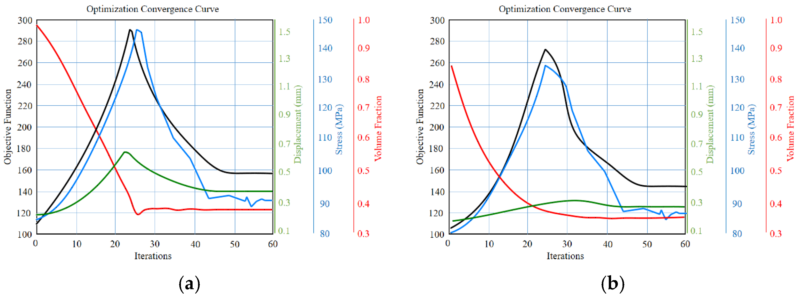
The objective function in this study is to minimize the structure’s compliance and, in other words, maximize its stiffness. Throughout the topological iteration, the objective function curve shows that the function becomes progressively smaller, indicating that the optimization makes the structure more rigid. The graph also traces the constraints specified for the model (volume ratio, displacement, maximum stress). The curves show that these constraints approach their limiting values as the iterations progress and eventually stabilize within the specified limits. After 59 iterations, both the objective function and the constraint functions converged; in other words, the optimization process stabilized and achieved the desired design objectives (
Figure 8).
In both methods, the optimization process begins with the full volume fraction (red curve) and gradually decreases towards the targeted lower levels as the iterations progress. Throughout this process, an increase in the displacement (green curve) and stress (blue curve), the mechanical responses of the system, is observed, and then, thanks to the structural adaptations of the optimization algorithm, they reach a stable level. In the SIMP method (left graph), fluctuations in the stress and displacement values along with the objective function (black curve) are noticeable, especially in the 20th iteration. This can be attributed to the SIMP method’s nature of allowing intermediate densities and stability issues arising from the continuous variation in element densities. In contrast, the BESO method (right graph) exhibits a similar initial increase, but the fluctuation is more limited, and the volume fraction and mechanical responses settle more regularly and steadily towards the target values. Both methods ultimately achieve the desired optimization goals by lowering the objective function and decreasing the volume fraction. However, the BESO method appears to converge faster, exhibit lower fluctuations, and provide a more stable solution compared to SIMP. This comparison demonstrates that BESO is an advantageous method over SIMP, particularly in engineering applications where stability and deterministic results are critical (
Figure 8).
In all three volume-reduction scenarios, the Abaqus–Matlab BESO method demonstrated consistently lower computational times compared to the Abaqus–Tosca SIMP approach (
Figure 9). At the highest volume reduction level, the SIMP method exhibited the longest computational time at 36 min, whereas the BESO method completed the optimization in 28 min. For the 50% reduction target, SIMP required 24 min and BESO 23 min, while in the 20% reduction case the corresponding times were 20 and 18 min. The extended runtime observed for the highest reduction level is primarily attributed to the initial stabilization process of the filtering parameters. Conversely, lower reduction levels converge more rapidly, as larger quantities of material are removed per iteration, thereby accelerating the overall optimization process.
The solution computer features an Intel i7-10510, 1.8 GHz CPU, 16 GB RAM, and 4 GB graphics cards. Although both methods take relatively similar times for the lowest 20% volume reduction target (approximately 18 min and 20 min, respectively), ABAQUS-Matlab BESO appears to require less computational time overall. These findings indicate that for this specific TO application, the Abaqus-Matlab BESO method has an advantage in terms of time efficiency over the Abaqus-Tosca SIMP method for different reduction targets.
The displacement values correspond to the maximum total deformation of the model, and the volume values indicate the reduction solid volume after optimization. Then the results were evaluated, it was determined that the model created using the BESO method was the most ideal solution. Compared to the conventional model, the von Mises stress and displacement of the new design increased by 52% and 8%, respectively, and the total volume decreased by 51%. This optimized design ensures that the catapult meets structural safety criteria and provides a stable platform that allows for precise alignment of the launch trolley. As a result, the static performance of the component has been enhanced, the negative impact of external influences on measurement accuracy has been reduced, and the lightweight construction requirements have been successfully met (
Table 3).
Although both SIMP and BESO were executed using the same volume reduction targets, slight differences appeared in the final solid volume, particularly in the BESO results. This is expected because SIMP enforces the volume fraction strictly as a mathematical constraint, whereas BESO controls volume through iterative element removal/addition, which may lead to deviations of ±3–5% depending on sensitivity filtering and evolutionary rate. Therefore, the small differences between the volumes in
Table 3 reflect the inherent algorithmic nature of BESO and do not indicate errors or inconsistencies.
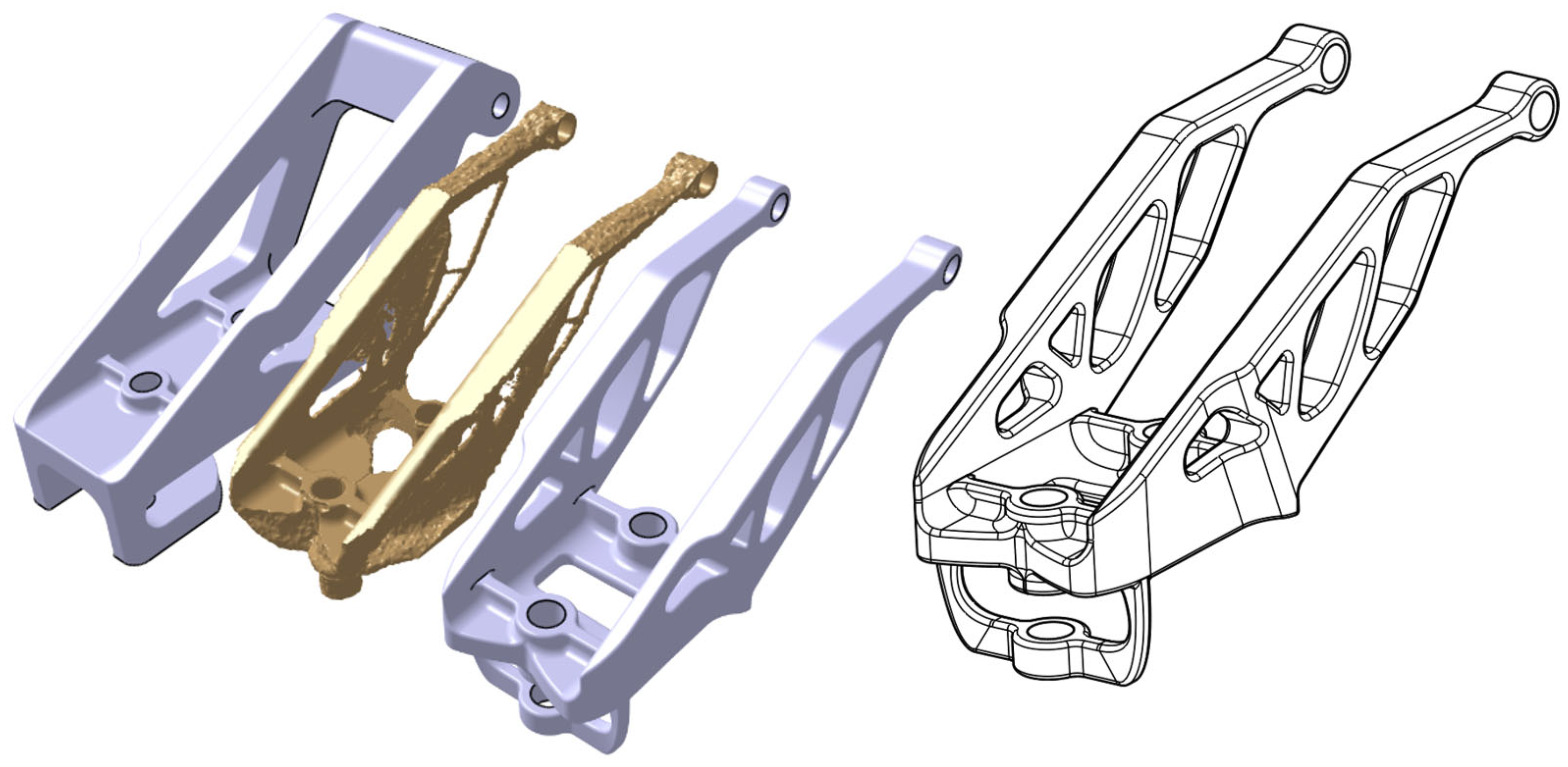
The geometries obtained using the BESO and SIMP methods are imported into STL (Stereolithography) format from ABAQUS software (
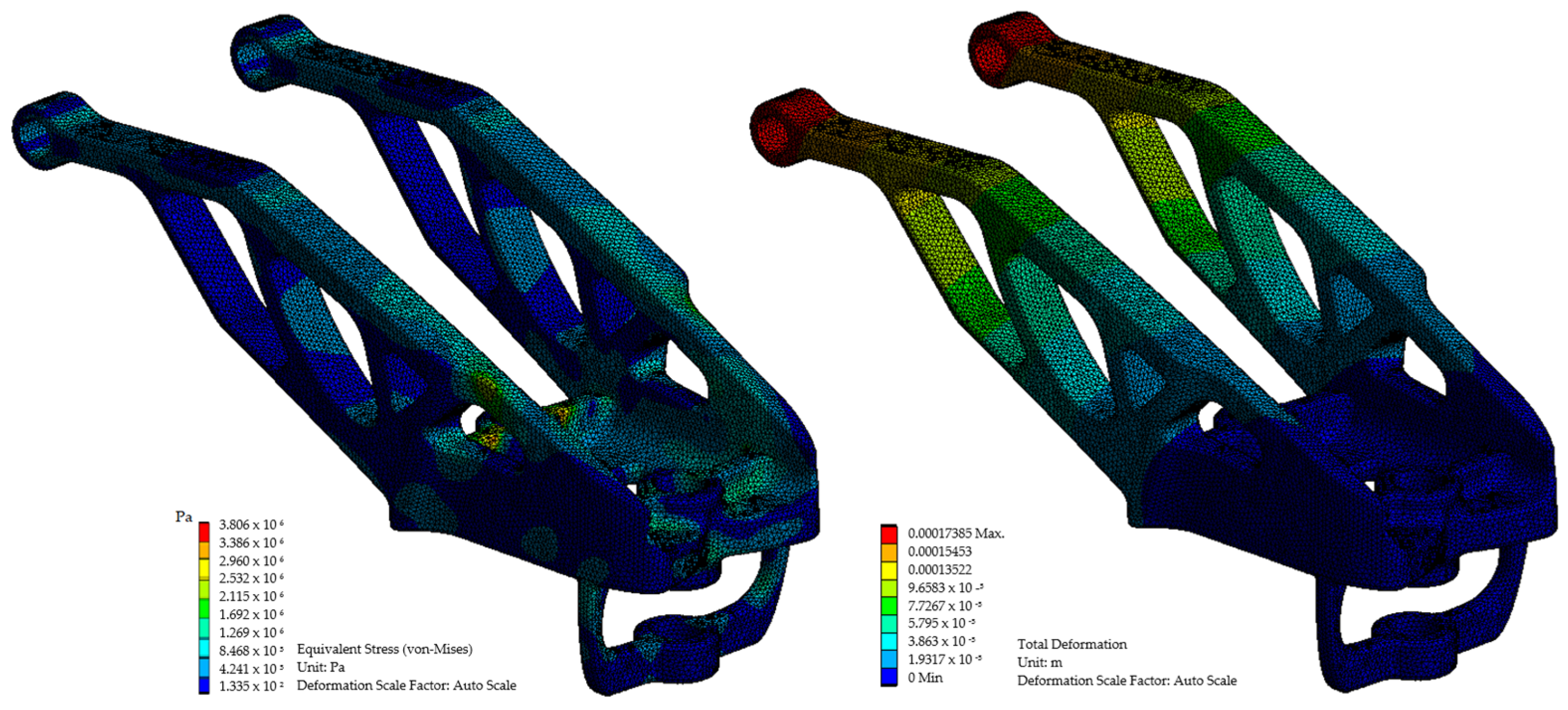
Figure 10). An STL model defines the surface geometry of a 3D object; that is, the geometry is stored as a triangular surface mesh. STL models are used in industrial part production with 3D printers. In this application, the obtained model through TO were redesigned using a solid modeling approach to suit the manufacturing strategy. Then, an FEA study was performed on the redesigned model (
Figure 11). When the stress and displacement results on the component were examined, they showed similar results to those of TO. The highest von Mises stress on the redesigned part was 38 MPa and the total deformation was 0.17 mm.
5. Discussion
In this study, the TO method based on SIMP and BESO was applied to a UAV launch trolley bracket subjected to high dynamic loads, which has critical structural importance. The results were compared in terms of multiple performance criteria. Both algorithms successfully achieved the specified volume reduction targets, resulting in significant improvements compared to the original design. Specifically, dramatic reductions of up to 70% in component volume were achieved, while structural stiffness was largely maintained. This demonstrates that TO, when properly applied, can provide a safe lightweighting solution. Furthermore, both methods achieved solutions without exceeding the predicted stress and displacement limits during the optimization process, thus ensuring that the final designs met all design constraints.
Weight reductions of up to 40% and stiffness increases of approximately 30% have been reported in the literature for similar parts subjected to TO [
3]. Similarly, Okorie et al. [
2] reported a 20% weight reduction on an aerospace bracket while maintaining the part’s initial displacement. In this context, the weight reduction and stiffness gains achieved in the study are consistent with the best results in the literature [
2]. With this, when examining the convergence behavior of the TO, significant differences were observed between the SIMP and BESO methods. Both methods gradually decreased the volume fraction from the initial full state to the targeted lower level over the iterations, and accordingly, the structure’s displacement and stress responses initially increased and then decreased to a stable level (
Figure 7). However, fluctuations occurred during convergence in the SIMP method: around the 20th iteration, significant oscillations occurred in the maximum stress and displacement values along with the objective function. This fluctuation can be attributed to numerical instabilities arising from SIMP’s continuous approach, which allows for intermediate densities. While a similar initial increase was observed in the BESO method, convergence was more regular and stable; as the iterations progressed, the volume fraction and structural response values reached the targets more uniformly. Consequently, the BESO algorithm exhibited a more stable convergence behavior compared to SIMP, reaching the solution in fewer iterations and with fewer oscillations. This demonstrates the advantage of BESO, especially in critical engineering applications where solution stability is crucial. This demonstrates the advantage of BESO, particularly in critical engineering applications where solution stability is crucial.
The BESO method also demonstrated superior performance in terms of computational efficiency. According to the results presented in
Figure 8, the ABAQUS-Matlab BESO application produced solutions in a shorter time compared to the ABAQUS-Tosca SIMP in all volume reduction scenarios. Specifically, when the highest volume reduction target was reached, the SIMP optimization required the longest computational time, taking 36 min., while the BESO optimization completed in 28 min. In this case, BESO achieved a significant time savings by reducing the computational time by approximately 22%. At the lowest volume reduction target (20%), both methods achieved similar computational times (SIMP 18 min., BESO 20 min.); although the difference is small, BESO is generally faster. The findings indicate that the BESO approach is advantageous in terms of time efficiency, even at different mitigation rates, and therefore may be preferred for optimization problems with intensive computational costs.
The optimized designs obtained with SIMP and BESO were also compared in terms of structural performance criteria.
Table 3 shows that both methods significantly increase the specific stiffness (bearing capacity per unit mass) compared to the original bracket, but the absolute stiffness of the structure (i.e., the total energy absorption capacity) decreases as the amount of removed material increases. In the moderate lightweighting scenario of 50% volume reduction (halving the mass), the SIMP and BESO results are nearly identical. For example, the total strain energy of the SIMP design was calculated as 6.22 × 10
4 Nmm, while that of the BESO design was calculated as 5.98 × 10
4 Nmm. The maximum von Mises stress values are almost identical at 48.6 MPa and 33.9 MPa, respectively. In this case, the SIMP solution exhibited slightly higher stiffness and slightly lower peak stress, while the BESO solution yielded a slightly lighter structure (BESO’s final volume was 583 × 10
3 mm
3, while SIMP’s was 628 × 10
3 mm
3). Remarkably, although BESO removed more volume than targeted in this scenario, it achieved structural performance very close to SIMP. This demonstrates the highly efficient material distribution of the evolutionary method; BESO was able to produce a solution with less material while maintaining the same stiffness and strength.
In the extreme lightening scenario (70% volume reduction target, leaving only 30% of the original mass), the differences between the methods became more pronounced. In this most aggressive case, the SIMP model showed in lower stiffness and higher stress values compared to the BESO model. Indeed, the total strain energy of the SIMP optimized model, 9.84 × 10⁴ Nmm, is approximately 25% higher than that of the BESO model, indicating that the BESO design remains stiffer with less material. Similarly, the maximum von Mises stress measured in the structure as a result of SIMP method is 48.68 MPa, approximately 15 MPa higher than the BESO result. This significant stress difference indicates that the SIMP method has difficulty distributing stresses evenly at very low volume fractions, and stress concentrations can occur in critical regions. In the same scenario, the displacement criterion was also more negative in the SIMP design. These findings suggest that the BESO approach is more effective in preserving structural performance under extreme lightening conditions. Presumably, BESO’s element-based selective removal strategy optimizes material distribution by preserving the most critical load-bearing paths.
In addition to structural improvements, the manufacturability of the optimized design was evaluated in the context of additive manufacturing (AM). The final geometry was analyzed for build orientation, minimum wall thickness, and support structure requirements. Both the SIMP- and BESO-based geometries were found suitable for Selective Laser Melting (SLM) and Fused Deposition Modeling (FDM) processes after minor design refinements. The minimum wall thickness of 2.5 mm and maximum overhang angle of 45° were confirmed as printable according to standard AM guidelines. The AA7075 aluminum alloy, chosen for this study, offers a high strength-to-weight ratio and good thermal conductivity, ensuring dimensional accuracy during the SLM process. The resulting structure therefore satisfies both mechanical and manufacturability constraints, demonstrating that the optimization approach is not only numerically robust but also practical for real-world aerospace applications.
6. Conclusions
In this study, a UAV catapult launch trolley bracket was optimized with two different TO methods (SIMP and BESO) and the outputs of both approaches were evaluated comparatively.
Thanks to the TO implemented in this study, a significant mass reduction was achieved in the original UAV catapult launch trolley bracket design. Lightweight reductions, reaching up to 50%, provided significant gains that directly increased the system’s portability and overall energy efficiency. Although this lightness caused a decrease in structural performance, critical engineering indicators such as stiffness, deformation and stress were positively improved. This resulted in a more advantageous structure in terms of both transportability and mission performance.
By rearranging the material distribution, the structural compliance the bracket was reduced, resulting in a significant increase in rigidity. The resulting designs after optimization showed 0.16 mm increase in displacement under the same load compared to the original model. This did not produce a significant impact on launch deflection and vibration, and improved the UAV’s takeoff accuracy and system stability as it remained within the desired tolerance range. Furthermore, the resulting von Mises stress value is well below the yield stress of the material. This stress allows the material to operate at lower stress levels, increasing fatigue strength and reducing the risk of unexpected damage. This makes the structure not only lighter but also safer.
Both optimization algorithms (SIMP and BESO) produced designs of similar quality and successfully met the specified objectives. Specifically, at the 50% weight reduction target, the SIMP and BESO methods achieved nearly equivalent stiffness, deformation, and stress values. However, the BESO method had the advantage in terms of computational time and exhibited more stable behavior during the convergence process. For higher weight reduction targets (e.g., 70% volume reduction), the BESO solution time was approximately 20% shorter than SIMP. Furthermore, fluctuations during the iteration process were less pronounced. On the other hand, the SIMP method, thanks to its continuous density approach, provides smooth geometric transitions, resulting in more homogeneous structures suitable for production. In this context, both methods have advantages, and the selection criteria can largely be determined by software capabilities, engineering priorities, and user experience. The manufacturability of the topology-optimized design was validated through SLM-based additive manufacturing feasibility analysis. The geometry satisfies minimum wall thickness, support, and orientation criteria, confirming that the optimization results are directly transferable to production.
Finally, the fact that designs obtained with different algorithms yield similar results demonstrates the reliability and accuracy of the optimization process. The final design was evaluated for manufacturability and remodeled to be suitable for additive manufacturing technologies (e.g., SLM or FDM-based 3D printers). The complex and lightweight lattice-like geometry, combined with the structural advantages offered by TO, allows for direct integration into modern manufacturing processes. This demonstrates that the proposed approach is not only theoretically valid but also valuable for practical engineering applications.
