Article

A Concept of Equivalent Load Scheme for Easy Prediction of Structural Topology When Load Position Changes Randomly

by
Bogdan Bochenek
and
Katarzyna Tajs-Zielińska
*
Faculty of Mechanical Engineering, Cracow University of Technology, 31-155 Cracow, Poland
*
Author to whom correspondence should be addressed.
Appl. Sci. 2025, 15(22), 12294; https://doi.org/10.3390/app152212294
Submission received: 19 September 2025 / Revised: 27 October 2025 / Accepted: 17 November 2025 / Published: 19 November 2025

Featured Application

The paper proposes a straightforward methodology for predicting topologies with minimized compliance for structures exposed to randomly varying load locations. Due to the occurrence of such loads in real-world structures, the method can be used for a wide range of industrial design applications. The concept may be implemented in the context of optimal engineering design, utilizing any algorithm or commercial software that allows finding topologies with minimum compliance involving multiple load schemes.

Abstract

The contemporary optimal design methodologies must be aligned with actual operating conditions of the structures, like, for example, load uncertainty—a situation which often occurs in engineering problems. This paper focuses on the topology optimization of structures under loads uncertainty, a situation which often occurs in engineering problems. It is worth underlining that random load changes can significantly affect generated topologies, therefore predicting them is an important design task. In this paper, a numerical approach suited to cope with this task is proposed. It is based on the idea that while minimizing structure compliance, random load changes can be mimicked by the deterministic problem of multiple load cases. This very useful approach, however, requires hundreds of load cases to consider. To reduce the number of load cases to a few, a new concept, the Equivalent Load Scheme—ELS, is proposed. This idea, being very simple, does not require specialized software to predict the structural topology of minimal compliance for uncertain point of load application. The implementation of this idea has been tested on numerical examples, including an engineering one. The results confirmed that the presented ELS concept can be regarded as a useful alternative to the existing techniques, significantly simplifying the design process. Taking into account the effectiveness, ease of implementation, and versatility, the proposed idea stands for an original contribution to structural topology optimization, suited for the case of loads exposed to random changes, in particular, when the position of the load changes randomly.

1. Introduction

Modern engineering design methods are nowadays based on advanced computer technologies. Artificial intelligence and machine learning, including computational intelligence and heuristic methods, are becoming increasingly important in structural engineering. Pioneering design methods are increasingly based on optimization techniques. This allows for the creation of durable, lightweight, and sustainable structures. Innovative methodologies in optimal design, including topology optimization, e.g., [1], shape optimization, e.g., [2], or generative design, e.g., [3], have led to a fundamental change in the field of mechanical engineering. High-performance computers have allowed the use of these methods in the fields of automotive, aerospace, biomedical, and civil engineering, e.g., [4,5,6]. Additive manufacturing has made them even more useful [7,8,9].
Topology optimization (TO), a concept that has been extensively discussed in the professional literature, has the potential to be applied in a variety of industries. The problems formulated within this field include designing in micro and macro scales [10], linear and nonlinear problems [11], static problems [12], dynamic problems [13], reliability and uncertainty [14], and much more. This paper focuses on problems where uncertainty and randomness in structural loads occur. Predicting optimized topologies for such structures, in terms of engineering practice, is very important due to the widespread occurrence of such effects in engineering problems. This topic has been discussed in the literature for decades [15,16] up to the latest papers, e.g., [17,18,19,20], including robust topology optimization for uncertain material properties [21,22] or multi-source uncertainties [23,24]. The studies conducted this year on transient dynamic loading [25,26], multiscale robust structural topology optimization [27], non-probabilistic reliability topology optimization [28,29], and fatigue reliability-based topology optimization as well as newly developed methods such as the stochastic method of moving asymptotes [30] have demonstrated the significant interest and considerable potential of the subject.
Introducing random parameters into calculations, both at the stage of structural analysis and optimization, usually greatly complicates the formulation and solution of the problem. The more complex the concept, the greater the demands on software and engineering skills. This paper aims to simplify complex calculations and proposes an alternative approach for predicting optimized structural topologies with minimal compliance in the presence of randomness of the structural load application point. In this paper, a concept of Equivalent Load Scheme (ELS) for easy prediction of structural topology is presented, which is not demanding for the software and users. This method can be successfully employed in combination with any optimization algorithm or with a commercial TO system, allowing its use in small- and medium-sized design offices that do not possess sophisticated software and highly specialized knowledge. This makes the method practical. The optimization algorithm utilized for this method can be a classical gradient-based algorithm or one of the modern methods.
In recent years, the role of heuristics and metaheuristics in modern design has been greatly appreciated. It is worth noting the paper in [31], which presents a comprehensive study on modern optimization techniques for engineering applications. In the context of biologically inspired methods, which have recently attracted the attention of designers, Cellular Automata (CA) represent a significant area of interest. This heuristic method was also used as an optimization tool in this paper. A Cellular Automaton is a mathematical idealization of a physical system that divides the design domain into a grid of cells. The states of these cells are updated in time steps in a discrete way according to a defined local rule determined by local information. Such a phenomenon of localized information flow has been observed in biological tissues. The concept of Cellular Automata was initially proposed in the late 1940s [32,33]. Following this pioneering contribution, CA began attracting considerable attention from researchers across a range of scientific disciplines (e.g., [34,35], or the latest [36,37]). As a tool for modeling complex structures, the Cellular Automaton is successfully used, due to its unique properties, also in engineering design as a modern optimization tool [38]. The earliest use of CA for structural optimization was in the mid-1990s [39]. Since then, it has become evident that CA can be the basis for efficient methods of optimal design—both sizing optimization and topology optimization [40,41,42].
For the purposes of this paper, CA approach was chosen as the modern and effective topology optimization tool. The choice was dictated by the advantages of CA as a fast and versatile method (see [41,43,44]). However, it should be emphasized that the main idea of the paper, i.e., ELS, can be implemented with any code that allows topology optimization to be performed, taking into account multiple load schemes. At this point, the idea is being tested for structures with minimal compliance with the predefined volume fraction constraint.
This paper is organized as follows. The problem of topology optimization is formulated in Section 2. The algorithm used to solve it is described herein, as well as the numerical technique for implementing random loads in topology optimization as a set of multiple loading cases. Subsequently, a new concept of ELS—Equivalent Load Scheme is introduced in Section 3. Section 4 of this paper presents case studies of the aforementioned approach, with a particular emphasis on the ELS technique. The discussion and conclusions based on the results are drawn in the final section of the paper.

2. Structural Design Using a Heuristic Approach to Topology Optimization

This paper focuses on topology optimization performed for the complex problem of designing the layout of structures in the case of random changes in load position. The innovative idea is introduced. Moreover, Cellular Automata, a modern method of optimal design, is utilized. This section presents the basis of the proposed concept.

2.1. Formulation of the Topology Optimization Problem

Topology optimization (TO) is a highly effective tool for achieving optimal designs in engineering, offering multiple valuable practical applications. This procedure can be defined as the process of material redistribution within a design space, with a view to minimizing a specific objective function. The process is usually undertaken strictly in accordance with the predefined constraints. In this investigation, the optimization problem is defined as a minimization of the compliance c, while a total volume constraint must be satisfied for κ, where κ is the available material volume fraction; see Equations (1)–(4):
m i n i m i z e         c d = U T K U = i = 1 N d n p u n T k n u n
s u b j e c t   t o       V = κ V 0
K U = F
0 < d m i n d n   1
The quantities in Equations (1)–(4) are defined as follows: U stands for the global displacement vector and F for the force vector; K is the global stiffness matrix. The element displacement vector is defined as u n , and the element stiffness matrix as k n . V 0 is a volume of the design domain.
The process of optimization is based on the discretization of the design domain into finite elements, for which the design variable d n , referred to as the relative density of the material, is defined. The idea of the material relative density was introduced in [45,46] and then developed and named as SIMP (Solid Isotropic Material with Penalization) in [1,47]. The presence of a physical material - solid element is denoted by the design variable d n equal to 1. Consequently, for d n tending to 0, the element can be treated as the void. The lower bound d m i n = 0.001 is defined for this investigation to avoid the instabilities in the finite element method utilization. The intermediate values of d n are eliminated by means of a penalization procedure that utilizes a power law E n = d n p E 0 , where p = 3 for these investigations, thereby driving the design to a solid/void structure. E 0 is used to denote the elastic modulus of a solid material.

2.2. Heuristic Optimization Procedure Based on Cellular Automata

In recent times, a significant number of contemporary optimization techniques have been developed for the purpose of performing analogous functions to those of biological systems [48,49]. In the context of optimal design, the Genetic Algorithms (GA) [50] or swarm-based metaheuristic algorithms [51] are the most widespread and developed, but those that are less common can be attractive for specialized applications like topology optimization. TO’s defining feature is its large number of design variables, which can make referring to the objective function computationally expensive. Consequently, algorithms not based on swarm intelligence have an advantage because they only need to refer to the objective function once per iteration step, rather than for each individual at each step. Among such algorithms is the Cellular Automata method, which was selected as the optimization tool for the illustration of the technique called ELS proposed in this paper.
The optimization process using CA can be divided into an analysis stage performed using the finite element method and a design variable update stage. The second stage is performed by a Cellular Automaton based on the information from the analysis. The details of this stage are as follows. The cells of the automaton are equivalent to elements in the finite element lattice. The state of each cell is described by the design variable d n , defining the relative density of the material. At each iteration step, the update of the design variable value can be performed according to Equation (5):
d n n e w = d n + d n
At this stage, the idea of local information exchange can be applied. For each cell in the design domain, a neighborhood that surrounds the central cell is defined. The information from the central cell and its neighborhood can be completed, and the average can be calculated as in Equation (6), where m is a move limit and M is the number of neighboring cells:
d n n e w = d n + F ( n ) + k = 1 M F ( k ) m M + 1 .
The update rules that govern CA algorithm performance are based on the information exchanged within cells forming neighborhood. This can be compared to the filtering technique based on averaging sensitivities calculated for elements surrounding the central one [1].
The function F n for the central cell n and F k for M neighboring cells can be calculated based on the rules proposed in [43]—see Equations (7) and (8):
F n = C     if     n < N 1 f n       if     N 1 n N 2 C       if     n > N 2 ,
where
f n = 2 C n N 2 N 1 C N 2 + N 1 N 2 N 1   .
In order to understand the idea presented, we need to recall compliance values calculated for each cell during the analysis process, rank them in ascending order, and then assign the appropriate number n according to this order: for the cell with the smallest compliance value n = 1, for the cell with the biggest n = N . Now, two values, N 1 and N 2 , where 1 < N 1 < N 2 < N , can be selected. When the compliance value for a cell is sufficiently low (i.e., its assigned value n is lower than the selected N 1 ), the coefficient -C is designated for this cell. It can be understood, in some generalization, as material removal, because such an assignment will consequently cause the relative density of the central cell to decrease. If the compliance value for the cell under consideration is sufficiently large, i.e., its assigned value n is greater than the selected N 2 , then the coefficient C is designated for this cell. It can be understood, to a certain extent, as adding a portion of the material and thus strengthening the cell. For all intermediate cells, a value between -C and C is assigned according to the linear function defined in Equation (8). For the purposes of this paper, C = 1 has been assumed. It is important to note that the parameters N 1 , N 2 may be constant during the iteration process, or alternatively, they may change their value, thereby changing the range of applicability of the function f n . Previous studies [43] prove that the implementation of the adaptive technique, characterized by a reduction in the interval [ N 1 , N 2 ], has the potential to accelerate the process of eliminating gray elements during the final stage of topology generation. While performing topology optimization for the test structures in this paper, the strategy for selecting values of parameters N 1 and N 2 is implemented as follows: the computations start with N 1   = N 0.02, and then from iteration 25 N 1   = N 0.5, from iteration 50 N 1   = N 0.7, and finally from iteration 75 N 1   = N 0.9, while N 2   = N 0.98 is kept for all iterations.
A global volume constraint is enforced to maintain a predefined material volume fraction κ ; see Equation (2). This constraint is applied after all local updates have been completed in a given iteration. In practice, this involves introducing a design variable multiplier, which is adjusted iteratively to ensure the volume condition is satisfied.

3. Predicting Structural Topology When Load Position Changes Randomly

3.1. Loads Applied at Random Positions Simulated by the Multiple Load Case

Random loads are an integral feature of real-world systems and should be taken into account during the optimization process. The article’s primary thesis posits the feasibility of employing a straightforward numerical methodology involving deterministic loads to model randomly varying forces while performing the structural topology optimization. The proposed approach is heuristic. It is based, first of all, on the observation that the problem of topology generation under loads exposed to random changes can be mimicked by the multiple load case approach. The paper focuses on predicting the topology of structures under forces whose point of application changes randomly. In [52,53,54], it was demonstrated that treating random loads as multiple load cases can generate topologies that are highly similar to those obtained in the standard way for randomly varying loads. However, even if this is considered to be valid, the need to take into account multiple load cases in order to emulate random loads increases computational costs, as each load case requires structural analysis. It would therefore be advisable to create a load scheme that uses a limited number of cases but gives a topology analogous to that obtained when random loads are taken into account. Therefore, an alternative Equivalent Load Scheme (ELS) has been proposed, oriented to cases when the position of loads changes randomly. A similar idea but suited only for the case of randomly changing the angle of load application has been recently discussed in [53].
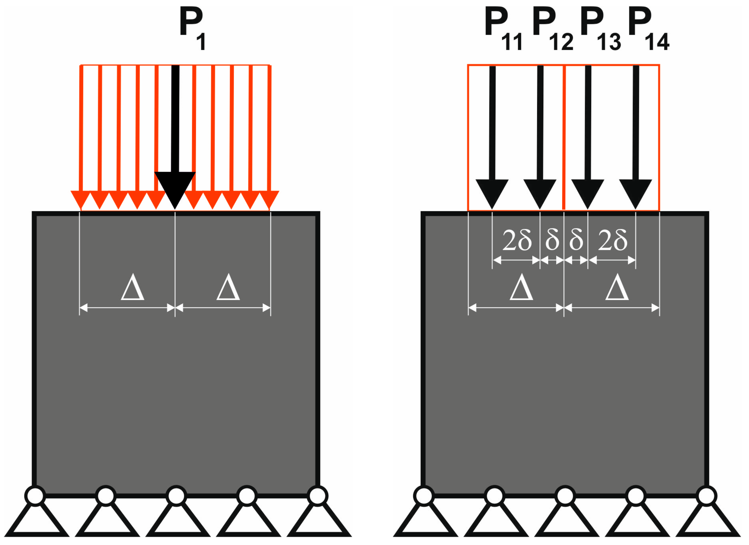
The structure under consideration as an introductory example is a square in shape, with 200 × 200 elements/cells in total, and is loaded with a deterministic force P = 1 N; see Figure 1 (left). The Young modulus E has been set to 1 N/mm2 and the Poisson ratio ν to 0.3. Topology optimization was implemented to minimize the compliance subject to a total volume constraint, for the volume fraction κ = 0.2, giving the final topology presented in Figure 1 (right).
In this part of the study, the load of a structure is exposed to random changes, with the point of application of the load chosen randomly from the range [−Δ, Δ] along the horizontal direction (see Figure 2).
In the preceding studies [54], the objective was to simulate the action of a load with a random point of application by replacing the random load with a set of at least 100 deterministic loads with randomly selected points of load application; see Figure 3 (left). A structural analysis was then performed for each of them. The resulting compliance of the structure is calculated as the average compliance value for each load case.

3.2. Equivalent Load Scheme to Represent Loads Applied at Randomly Selected Positions

To minimize the number of load cases and therefore the computational time, the idea was selected to use only four load cases, which can mimic the results of a primary large set of randomly selected forces, i.e., randomly selected points of application of the forces; see Figure 3 (left). Four equidistant force application points were selected, see Figure 3 (right), and the structure topology was generated for the four load cases, namely P11, P12, P13, and P14.
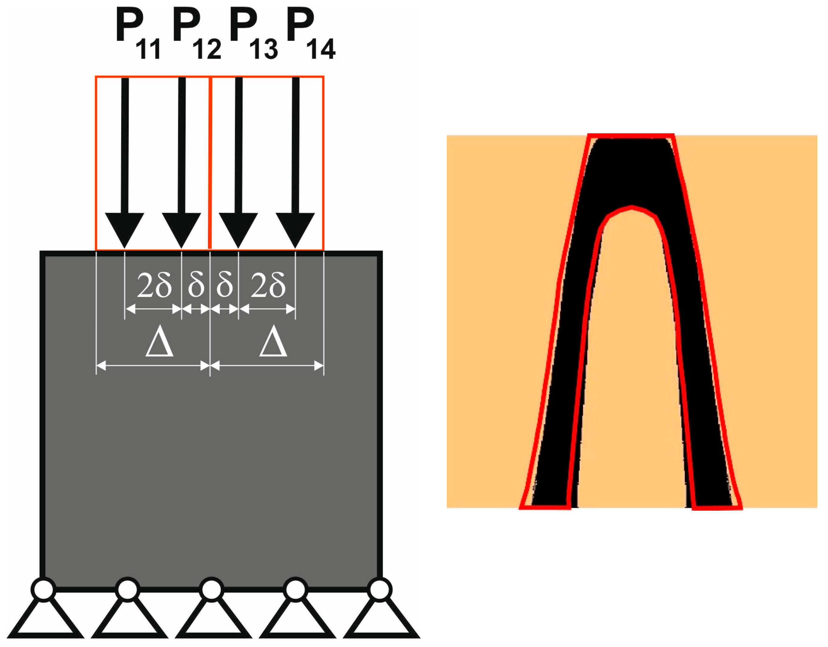
It was assumed that the topology obtained in this way would be equivalent to the topology of a structure loaded with a force whose position is randomized within the range [−Δ, Δ]. The final topologies presented in Figure 4 show the compatibility of the two resulting structures.
Based on these observations, it was concluded that it is possible to replace forces acting at randomized positions by the deterministic Equivalent Load Scheme in order to perform the topology optimization process. This numerical heuristic approach significantly simplifies the complex initial problem and reduces computation time. Moreover, the proposed concept can be applied to any code that allows the generation of structural topologies with minimal compliance under multiple load schemes. No additional software is required.
The reasoning of how to select ELS is presented based on the introductory example from Figure 1. The topology for the set of loads applied at randomly distributed positions is generated first. Random load positions s i are selected within the range ,   s i = ( 2 r 1 ) , where random number r is taken from the uniform distribution. The result is presented in Figure 5. The compliance for the final topology equals c = 10.467 Nmm.
The first choice for ELS is to select a pair of loads, each applied in the middle of the load position range , δ = / 2 .
The obtained topology is presented in Figure 6 (right). The outline of the topology generated for the stochastic load set has been applied to Figure 6 (right), in order to enable comparison. One can observe that the topologies fail to coincide. The compliance computed for the final result equals c = 9.125 Nmm and when compared to the one computed for the stochastic load results in 12.8% difference.
The next attempt is the 4-load ELS ( δ = / 4 ) scheme which is shown in Figure 7 (left). The generated topology is presented in Figure 7 (right); compliance for the final result is equal to 10.036 Nmm. In this case, the good topologies resemblance is observed and the difference in compliance values is smaller than 5%.
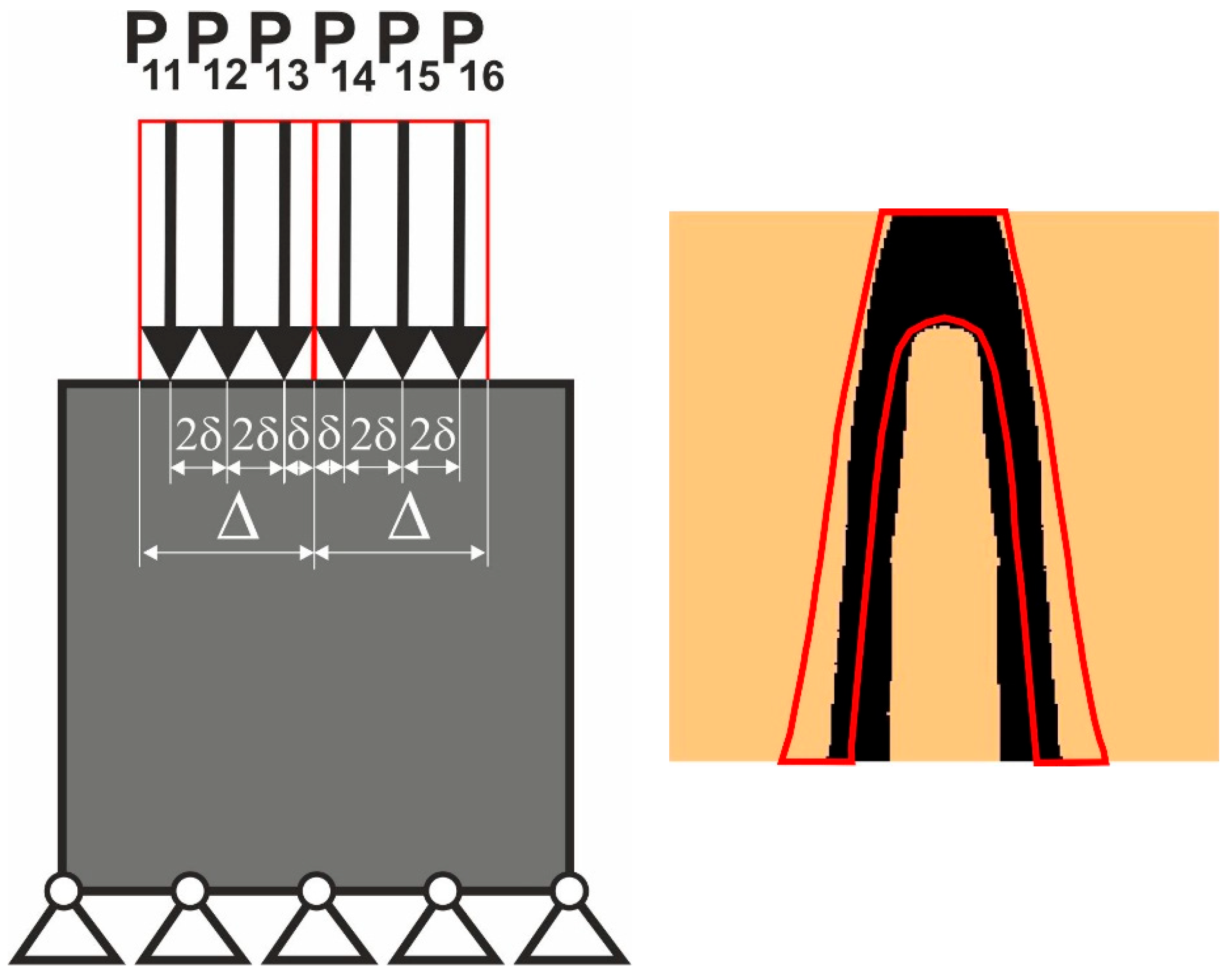
The 6-load ELS ( δ = / 6 ), shown in Figure 8, has also been considered. The final topology of the compliance value 9.345 Nmm is presented in Figure 8 (right). It is seen that the implementation of this scheme resulted in poor topologies resemblance and a significant difference in compliance values—10.7%.
On the basis of the above reasoning, the 4-load ELS has been proposed for further tests.

4. Results

In order to illustrate the proposed methodology, a set of representative test examples has been selected. The computational procedures were performed using an original in-house algorithm implemented in the MATLAB 2020b environment.
As to the type of neighborhood, the Moore one, where the neighboring cells have common vertices with the central cell, has been selected for computations for all discussed examples. As to the stopping criterion, the fixed number of iterations has been chosen.

4.1. The Test Structure 1

The first test is performed as a reference to a well-recognized simply supported plane structure, also mentioned in the paper in [54]. The test structure 1 under a single deterministic load, shown in Figure 9, is discretized into 120,000 (1 mm × 1 mm) finite elements (600 × 200). Material data E = 1 N/mm2, ν = 0.3 were defined, and the volume fraction κ = 0.5 has been selected.
Under a single deterministic load, the structure is subjected to a force P, applied at the center of the upper edge. The final topology for this case can be found in [54]. Concurrently, the final topology obtained for the considered structure under a load applied at randomly selected positions is presented in the aforementioned paper and in Figure 10 below as a recollection. This serves as an illustration of the primary concept to transform a random load case into the deterministic problem of multiple loads with randomly selected positions of load application. In this example, the 100 load cases are considered, and the randomly selected positions of load application vary within the range [−Δ, Δ].
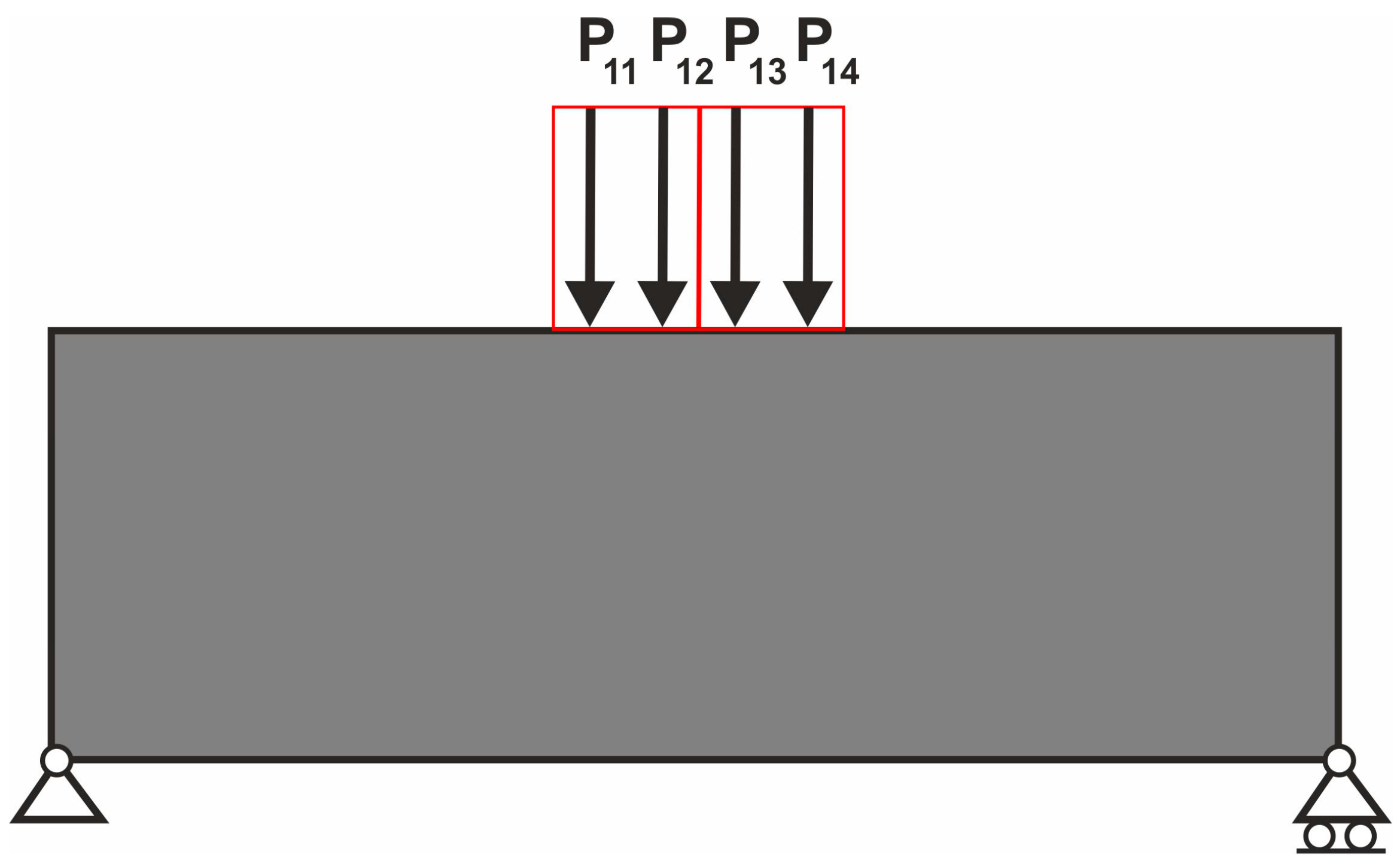
Using the transformation of random loads into a deterministic problem of multiple loads as a basis, the concept of Equivalent Load Scheme ELS can be introduced. In place of generating a multitude of random loads, the four representative load cases are implemented, as shown in Figure 11.
The topology optimization process was carried out for the 4-load Equivalent Load Scheme ELS, resulting in the topology presented in Figure 12.
In consideration of the equivalency of the final topologies presented in Figure 10 and Figure 12, it was determined that the Equivalent Load Scheme (ELS) facilitated the prediction of the structures topology under load applied at randomly selected positions.
As an illustration of a detailed comparison of the topologies obtained for the test structure 1, the following Figure 13 and Figure 14 may be used.
The contour of the above-presented shape obtained for the set of loads applied at random positions—multi-load case, has been applied to the ELS shape in Figure 14 below.
The shapes are practically identical.

4.2. The Test Structure 2

Following this line of thinking, comparative calculations were performed for the second test structure shown in Figure 15. The regular mesh of 204,800 (640 × 320) elements/cells (1 mm × 1 mm), the volume fraction κ = 0.4, and E = 1 N/mm2, P = 1 N, ν = 0.3 have been applied.
In order to model the topology for a structure under load with an uncertain point of application, a deterministic load scheme was utilized. This scheme comprised 100 load cases, with the positions of load application being randomly selected and varying within the range [−Δ, Δ]—see Figure 16. This test structure was also investigated in [54].
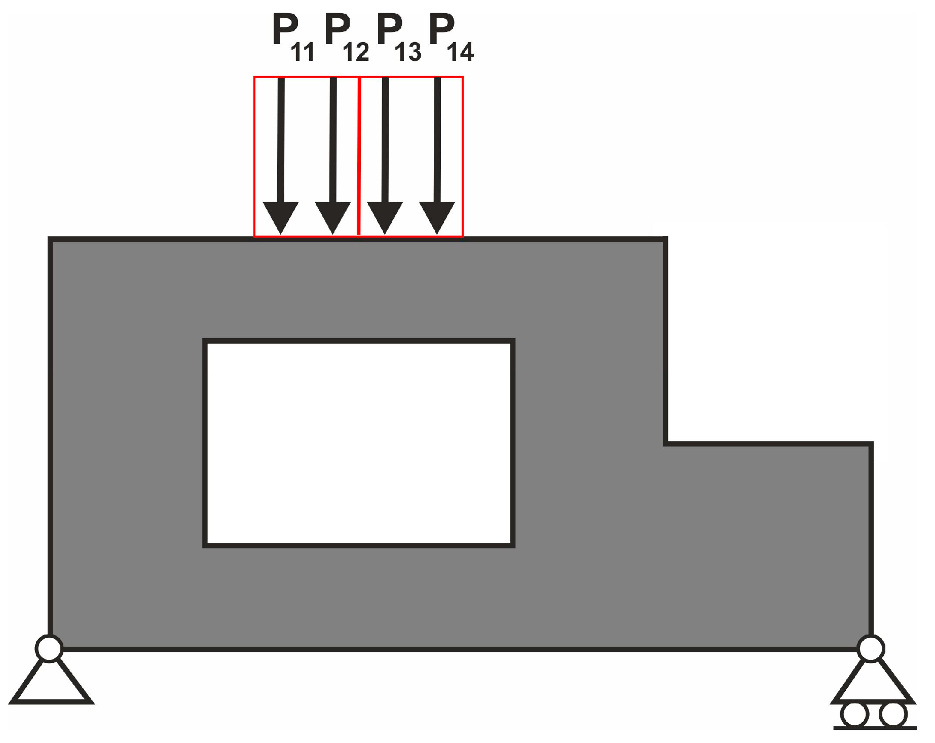
The 100 load cases scheme, according to the idea proposed in the paper, can be replaced by only four load cases, as shown in Figure 17, which presents the ELS for the considered example.
As a result, the final topology shown in Figure 18 has been obtained. One can observe the compatibility of the two resulting structures.

4.3. The Test Structure 3

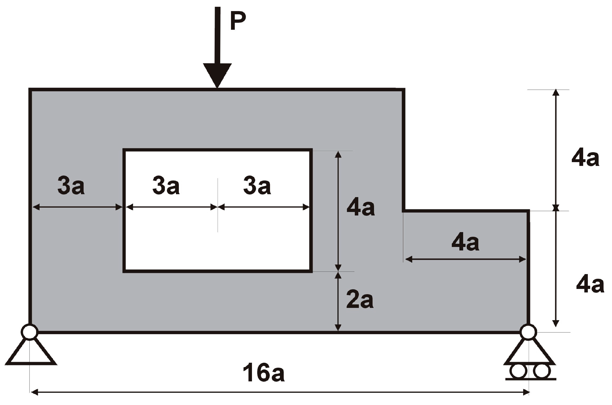
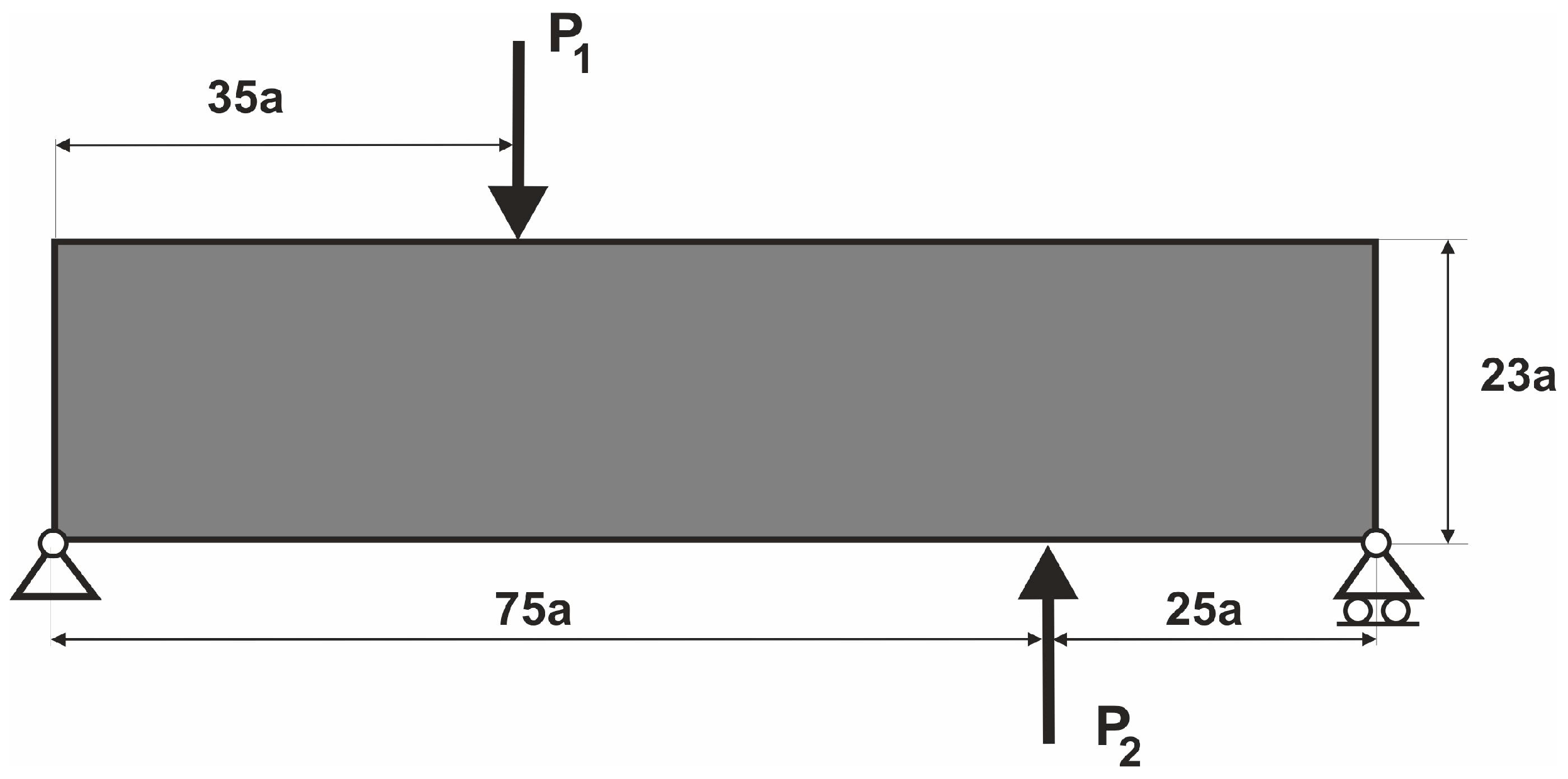
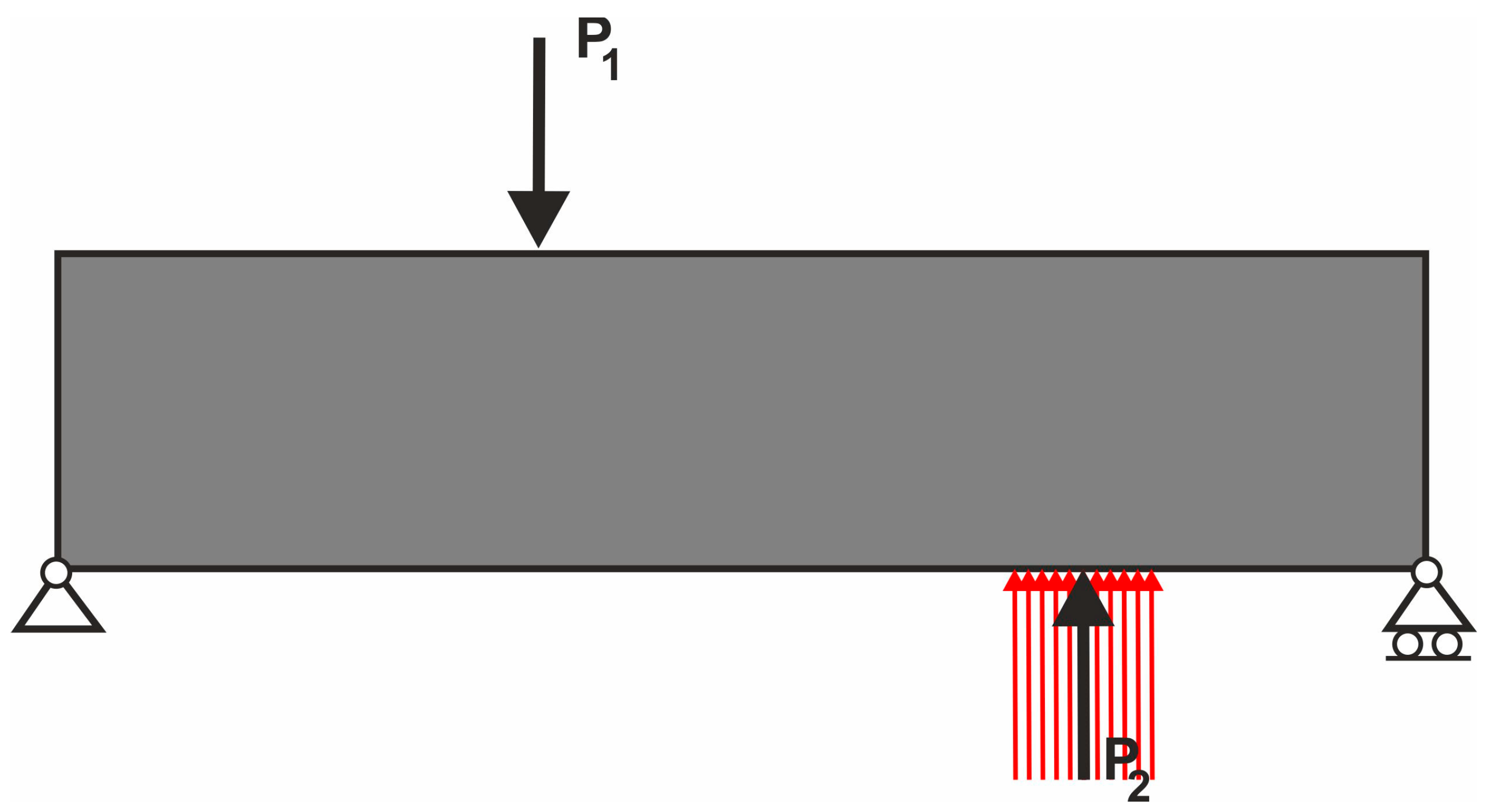
For the proposed test structure 3, initial computations were performed for two simultaneously operating loads for the deterministic case—see Figure 19 for an illustration of the applied loads and Figure 20 for the final topology for this deterministic case. The following parameters were applied: a regular mesh of 230,000 elements/cells (1000 × 230), volume fraction κ = 0.5, E = 1 N/mm2, P1 = P2 = 1 N, and ν = 0.3.
In the next step, it is assumed that force P1 can act at a randomly selected point of application, and therefore, a set of 100 load cases modeling such behavior has been adopted, as it is schematically presented in Figure 21. The corresponding final topology is presented in Figure 22.
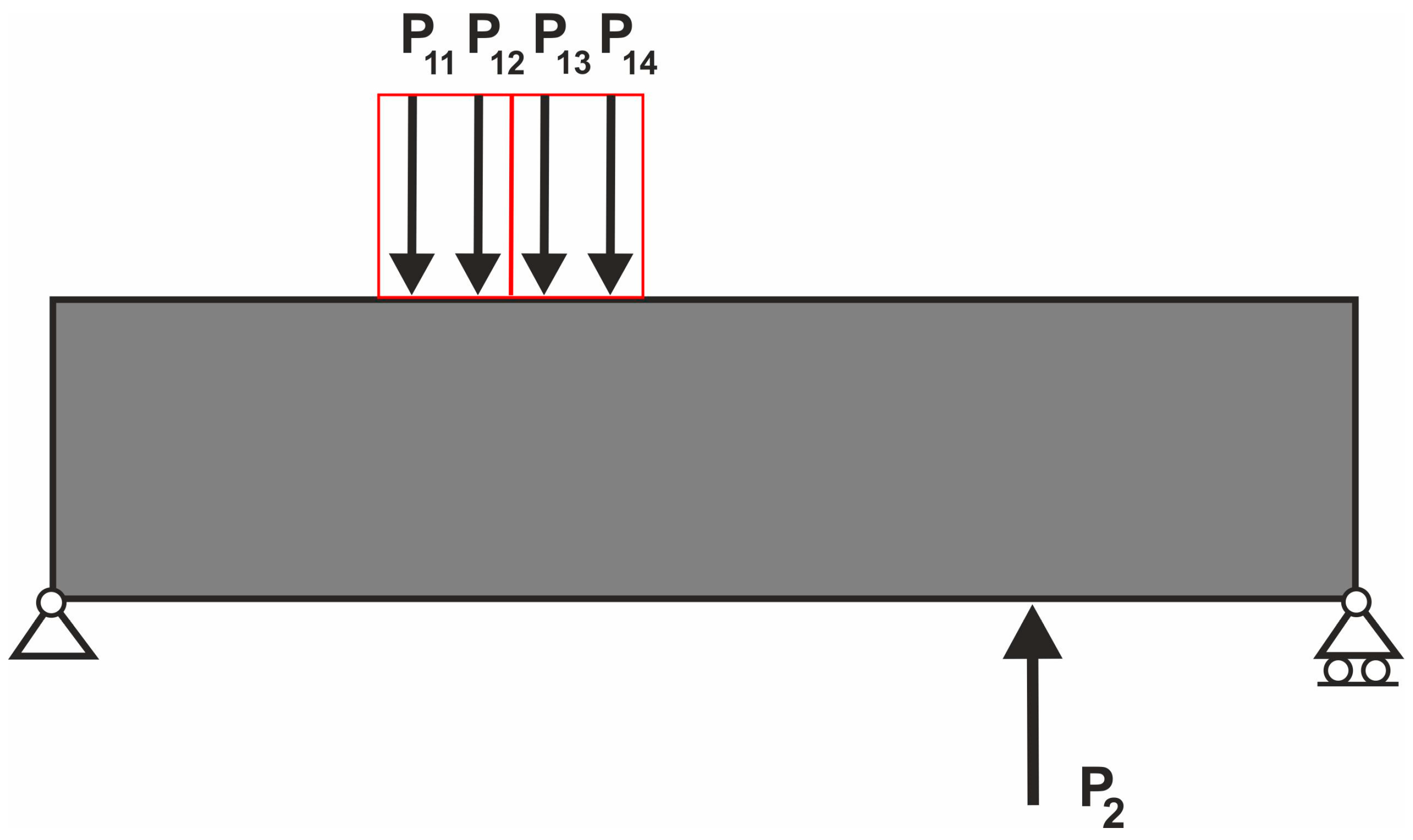
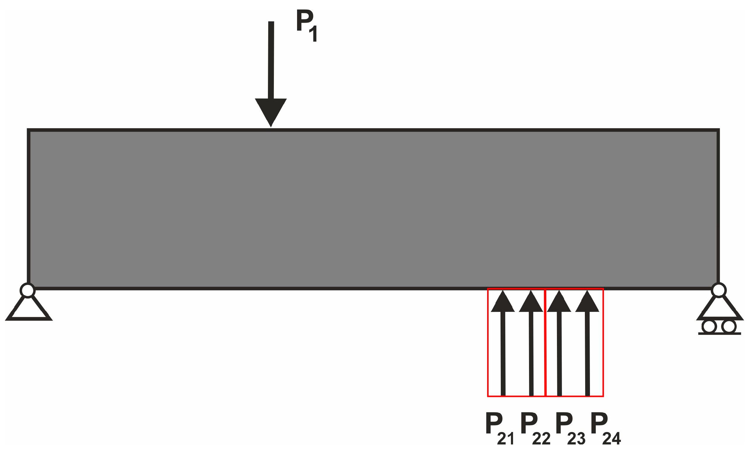
Now, to reduce the number of load cases, an equivalent scheme illustrated in Figure 23 has been used, with substitute forces acting in tandem with P2, so the four schemes look as follows: P11 + P2, P12 + P2, P13 + P2, P14 + P2. As a result of the optimization process, the resulting topology shown in Figure 24 has been obtained.
In what follows, it is assumed that now the force P2 is applied at randomly selected points, and a set of 100 load cases mimics such behavior, as it is schematically presented in Figure 25. The force P1 remains fixed. Figure 26 shows the final topology obtained for this case.
The four loads Equivalent Load Scheme (ELS) for this variant is as follows: P1 + P21, P1 + P22, P1 + P23, P1 + P24; see Figure 27.
As shown above, the 100 load cases scheme can be successfully replaced by only four load ELS, the final topologies for both cases are practically identical, as shown in Figure 26 and Figure 28.

4.4. Test Structure 3 for Two Independently Acting Forces

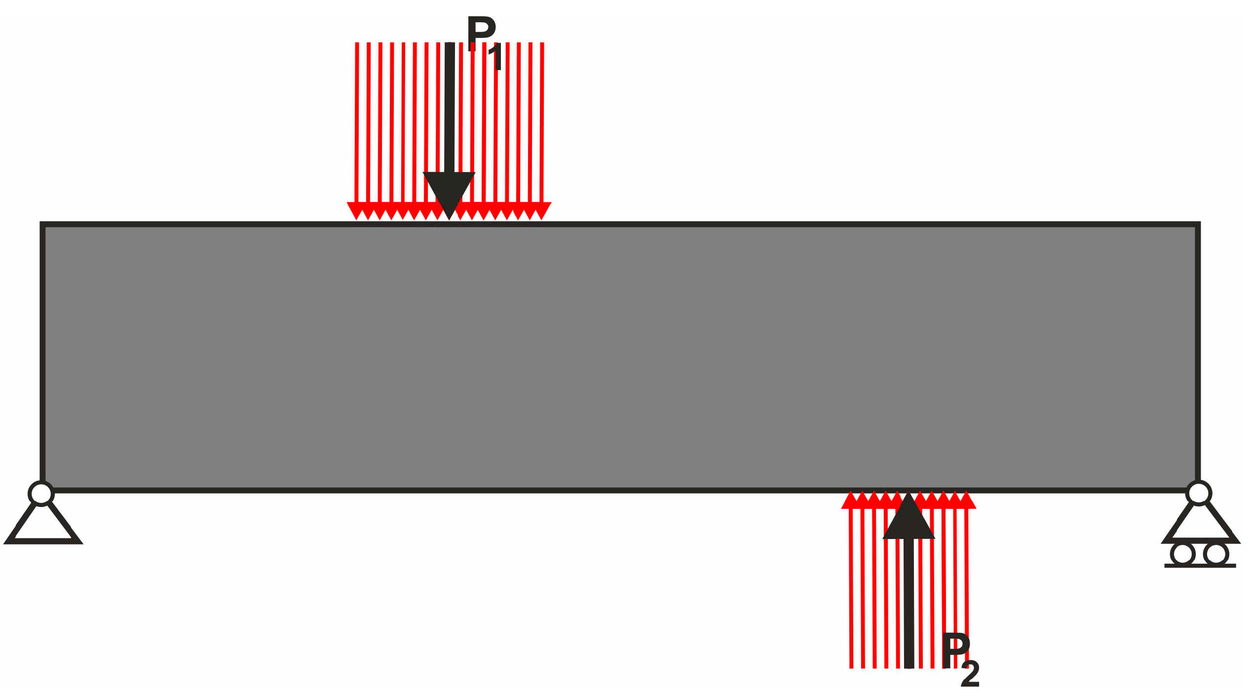
The next step of implementation of the ELS concept is the possibility of taking into account the effect of a combined loading in the case of a random point of application. It is therefore stated that the positions of both forces P1 and P2 are treated as random. This case can be modeled using two sets of 100 load cases (Figure 29), which, as a result of the optimization process, give the final topology shown in Figure 30.
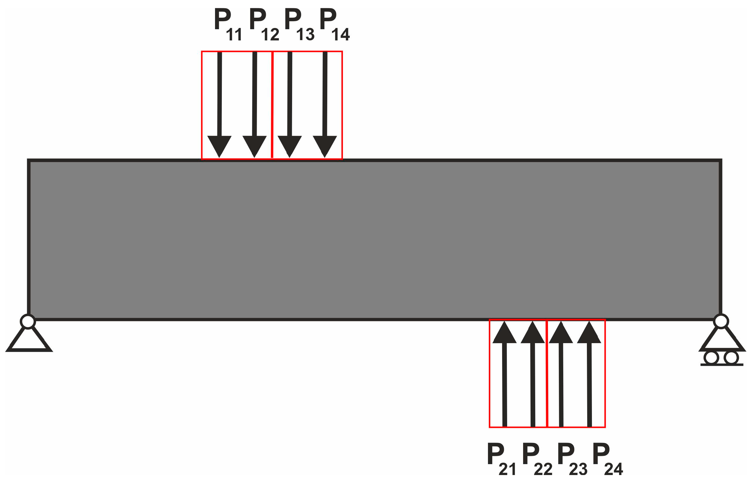
For this complex case, the ELS consists of 16 load cases, namely P11 + P21, P11 + P22, P11 + P23, P11 + P24, P12 + P21, P12 + P22, P12 + P23, P12 + P24, P13 + P21, P13 + P22, P13 + P23, P13 + P24, P14 + P21, P14 + P22, P14 + P23, P14 + P24; see Figure 31. The result of topology generation is presented in Figure 32.

4.5. Test Structure 4—Asymmetric Range of Random Load Positions

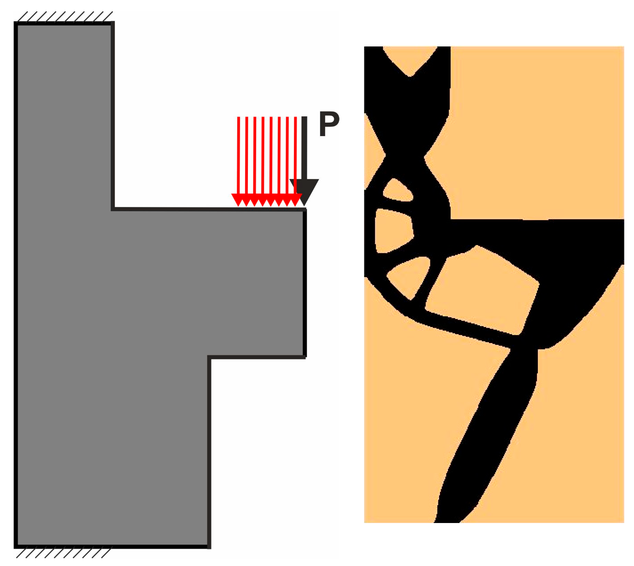
Continuing to test the possibilities of application of the proposed ELS idea, the case of an asymmetrical range of random load positions is examined. Let us consider the structure shown in Figure 33 (left), loaded with a concentrated force applied at the corner. The following parameters were applied: a regular mesh of 165,000 elements/cells (300 × 550), volume fraction κ = 0.3, E = 1 N/mm2, P = 1 N, and ν = 0.3. The final topology obtained for the deterministic case is presented in Figure 33 (right).
The design space represented by the gray area excludes randomly selected application points from appearing symmetrically. The random application of force can only be considered in one direction, as shown in Figure 34 (left). The calculations were performed for 100 deterministic load cases for which the load position was randomly selected, resulting in the final topology shown in Figure 34 (right).
The Equivalent Load Scheme for this case is selected as shown in Figure 35 (left), and the obtained final topology is presented in Figure 35 (right).

4.6. Engineering Example—Brake Pedal

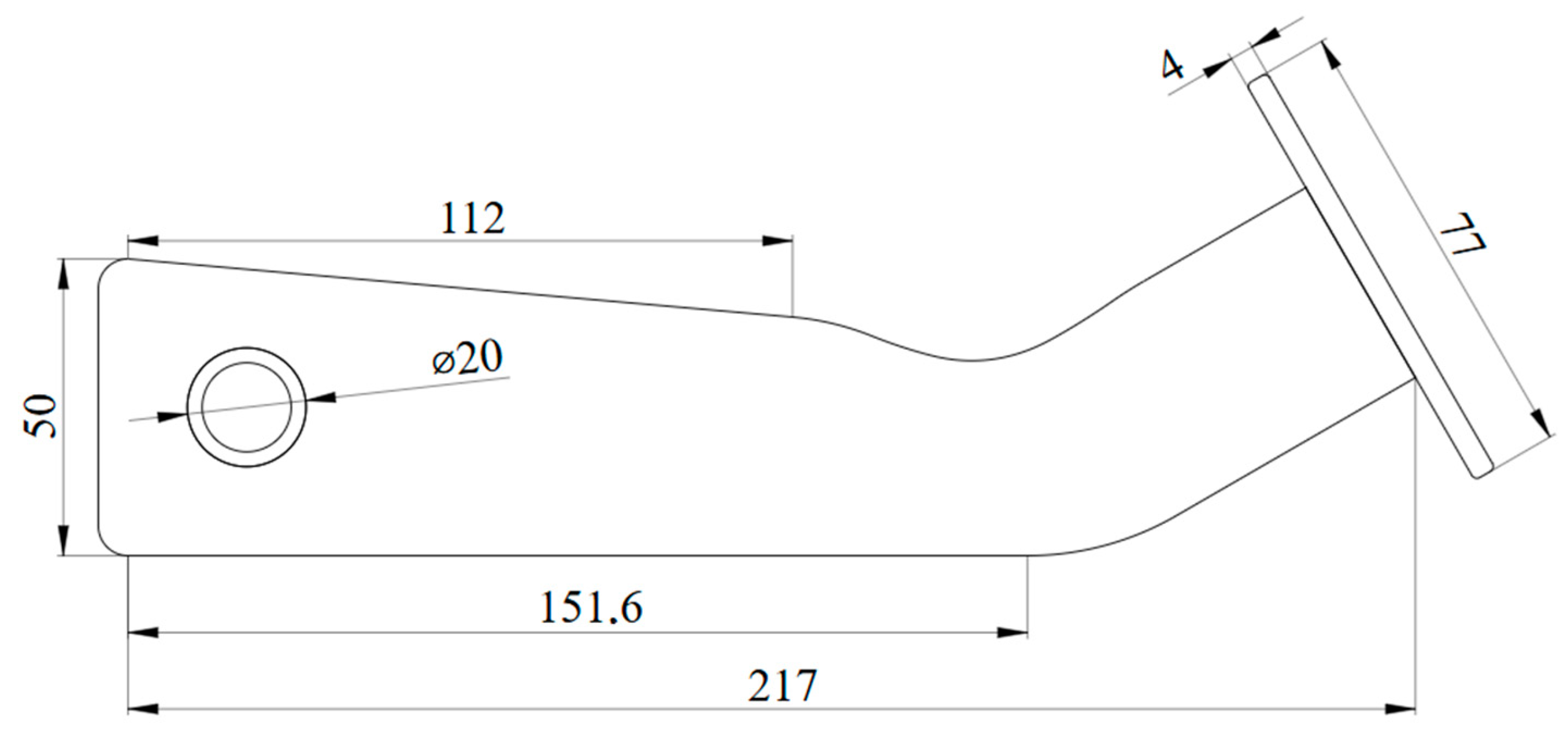
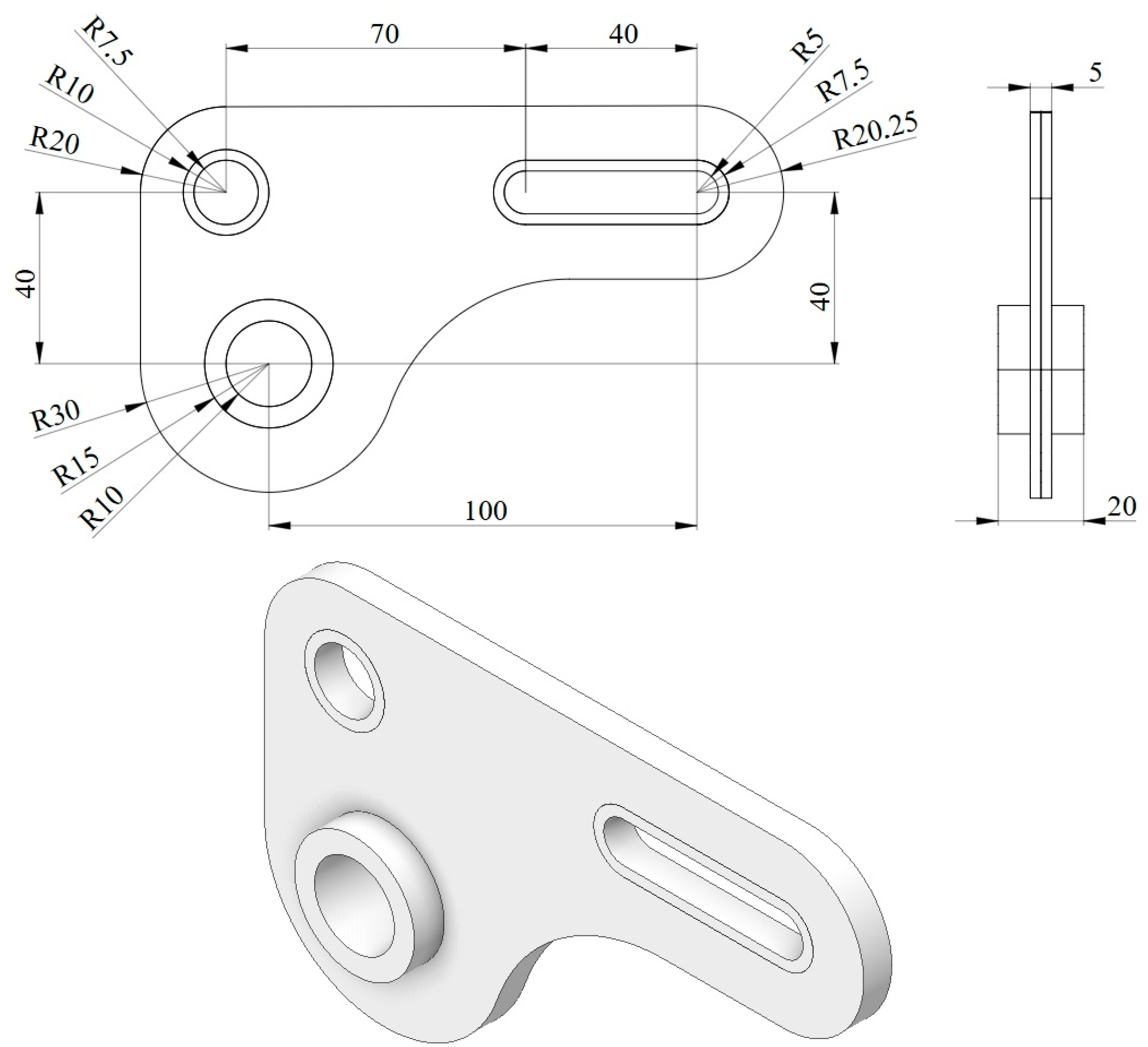
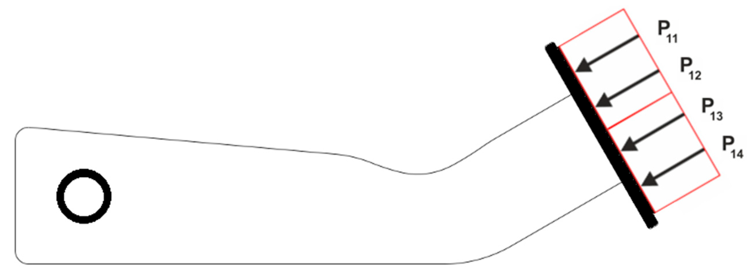
As the engineering application of the ELS concept, the brake pedal model has been chosen. The overall dimensions are shown in Figure 36. The material data for this example are defined as follows: E = 10 GPa and ν = 0.35. It was assumed that the volume fraction is κ = 0.5.
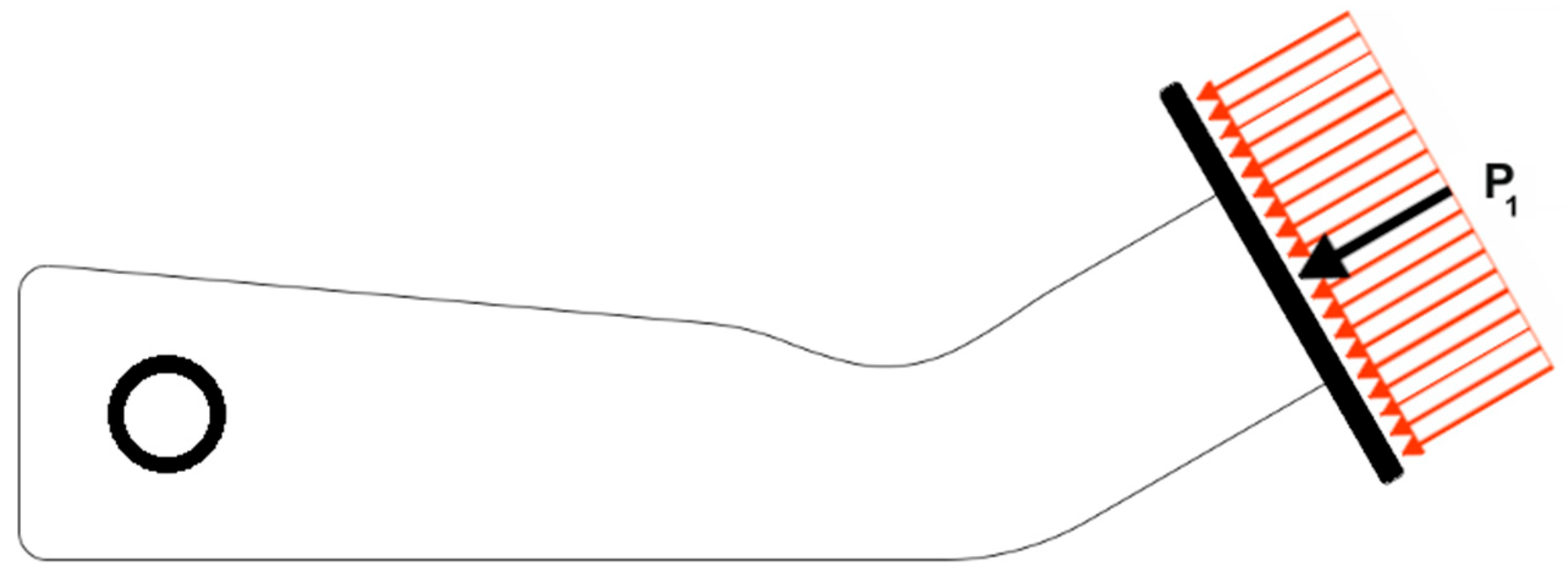
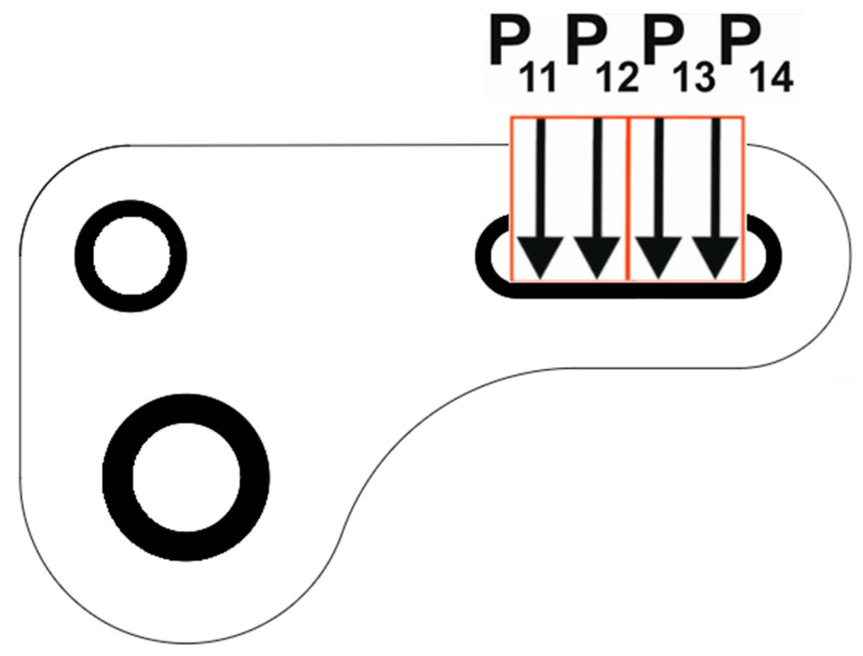
The design space is divided into areas subjected to optimization and excluded ones (Figure 31—black areas). Inside the mounting hole on the left, all degrees of freedom are constrained. Position of the force P1 = 500 N, shown in Figure 37, changes randomly. The 300 load cases mimicking such behavior have been adopted—it is schematically presented as red loading in Figure 37.
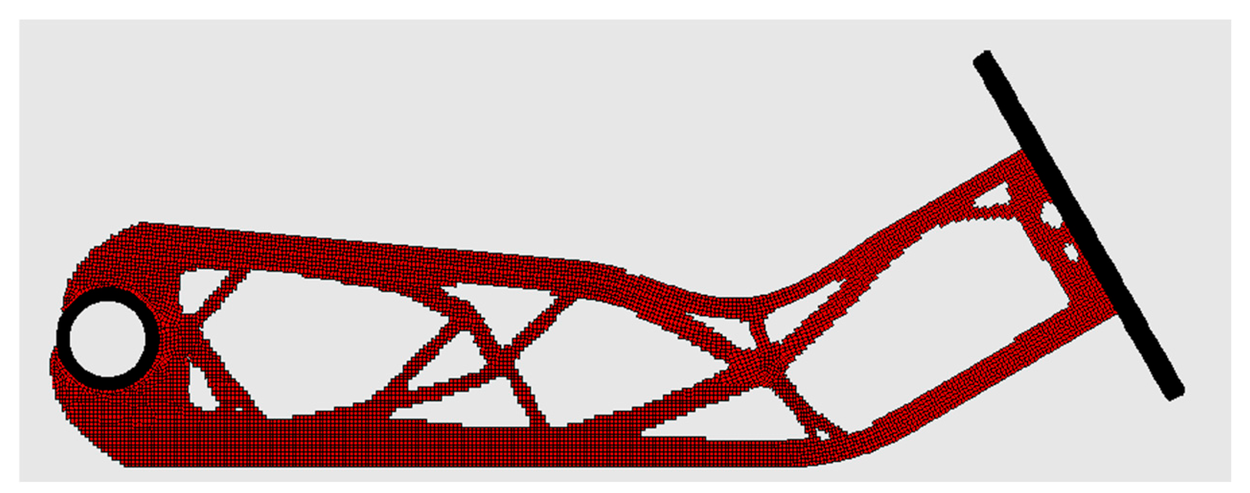
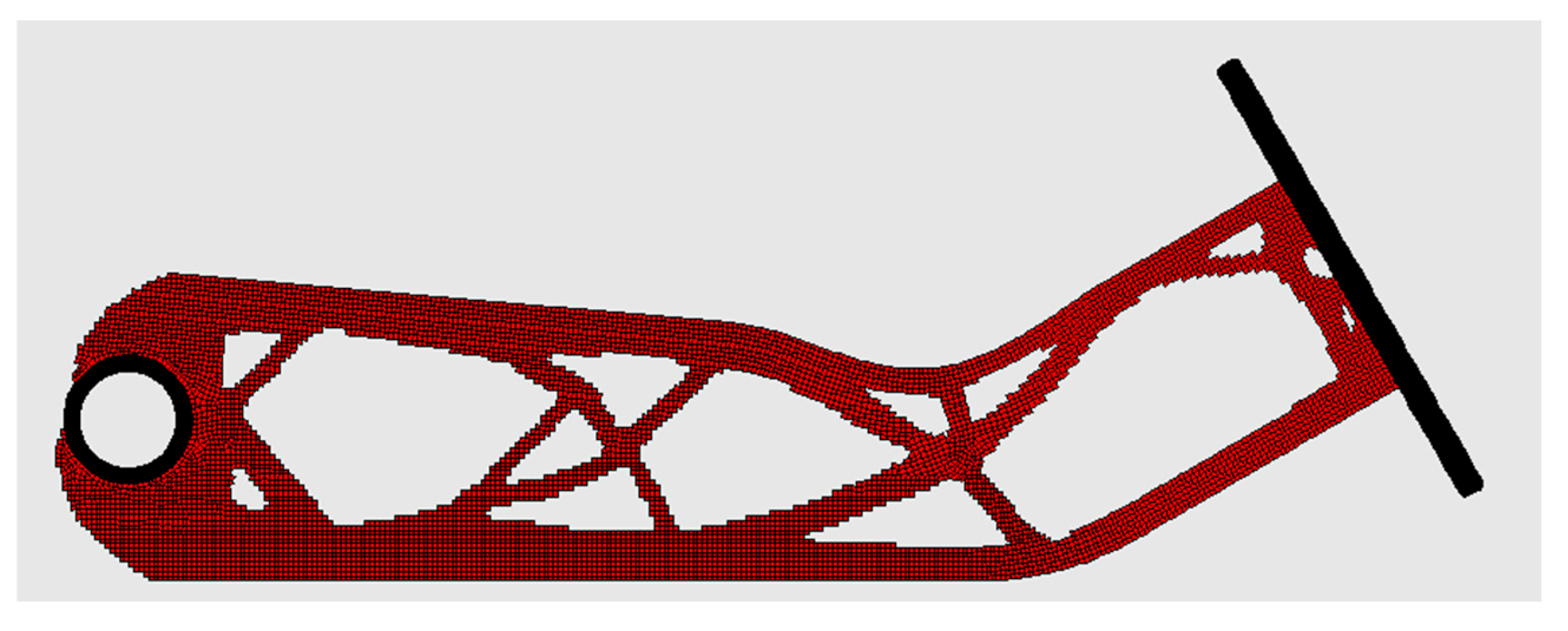
The final topology for the problem formulated in this way is presented in Figure 38.
The next step is to introduce the Equivalent Load Scheme; see Figure 39.
The final topology for the problem formulated in this way is presented in Figure 40. One can observe that there is practically no difference between the two obtained topologies.
For the engineering structure, the Ansys Mechanical APDL 2025R1 was used as the analysis tool, while the optimization process was controlled by in-house code written in FORTRAN. The use of a commercial analysis package allows for the analysis of arbitrarily complex geometries, which broadens the application of the idea proposed in the paper.

4.7. Engineering Example—Lever Arm

The ELS concept can be easily applied to three-dimensional tasks with complex geometry. The lever arm shown in Figure 41 was selected as an example. The material data used in the computational model are defined as E = 2.1 GPa and ν = 0.35, while the volume fraction is κ = 0.5. The design space is split into two sections: regions that are subject to optimization and those that are excluded (see Figure 42, black volumes).
The horizontal degrees of freedom are constrained in the upper left mounting hole, while the vertical degrees of freedom are constrained in the lower left mounting hole. The position of the force P1 = 200 N (see Figure 42) fluctuates randomly. This phenomenon can be replicated through the implementation of 300 load cases, as depicted by the red loading in Figure 42.
The final topology corresponding to the formulated problem is shown in Figure 43.
In order to predict the topology of a structure loaded with a random point of load application without having to perform calculations for a large number of load cases, ELS was used with equivalent forces defined as shown in Figure 44.
The final topology corresponding to the problem formulated in this manner is shown in Figure 45.
As in the previous example involving complex geometry (see Section 4.6), Ansys Mechanical APDL 2025R1 was employed as the structural analysis tool, while the optimization process was managed by an in-house FORTRAN code.

5. Discussion and Conclusions

The easy-to-implement approach to predict structural topologies in the case when load position changes randomly has been introduced and its performance has been illustrated by several numerical tests. The straightforward methodology for topology optimization, converting loads that change randomly into a set of deterministic loads treated as multiple loads case, has been utilized. Since the direct implementation of this approach usually requires hundreds of load cases to be considered in order to mimic random load location, to reduce the number of load cases to a few, a new concept of Equivalent Load Scheme—ELS has been introduced. Although not mathematically rigorous, this heuristic concept allows prediction of final topologies for the considered case of load randomness. From the applied sciences point of view, such a numerical tool supporting engineering design may be of practical value.
Several numerical tests have been performed to verify the proposed concept. For the test structures, the resulting topologies obtained both for the sets of loads located at randomly selected positions and for the suitable Equivalent Load Schemes have been generated. The detailed presentation of the results is given in Section 4.
It started with the rectangular test structure 1, followed by the test structure 2 of slightly more complicated geometry. The comparison of obtained results shows that the resulting topologies based on implementation of the Equivalent Load Scheme coincide with the ones resulting from application of the straightforward multi-load case approach. The test structure 3 is loaded by two forces and the topologies have been generated for the case when the position of one load is randomized while the other remains fixed, as well as for the case when the positions of both loads change randomly independent of each other. The Equivalent Load Scheme has also been successfully applied to the case of an asymmetric range of random load positions. It is worth underlining that for a single load, the ELS approach requires only four load cases in order to generate a suitable topology. For more complicated loading schemes, the ELS approach requires more loading cases to consider, but their number is still significantly lower compared to the straightforward method. The engineering examples presented in Section 4.6 and Section 4.7 validate the application of the proposed technique in practical engineering designs. The models of a brake pedal and lever arm have been chosen for this purpose. The results presented show that the topology obtained using the ELS is practically identical to the one resulting from implementation of the direct approach involving a few hundred load cases.
The topology resemblance has been supported by a quantitative metric based on compliance values. In what follows, the compliances are computed for both sets of randomly selected positions of load application and for ELS (see Table 1). One can observe that the differences in compliance values do not exceed 3%.
The algorithm built as a Cellular Automaton has been effectively used for computations. The minimal compliance topologies have been generated without greyscale and checkerboard effects. The performance of the algorithm is easy to control. The process of topology generation is fast due to its non-swarm nature, i.e., the algorithm refers to the value of the objective function only once in each iteration. It is important because when using the finite element method for complex structures with a large number of finite elements, the analysis can be computationally expensive. It is also worth noting the ease of the algorithm implementation even for users without advanced knowledge within the field of topology optimization.
The multiple load cases approach mimicking load randomness and the Equivalent Load Scheme built on this background are not linked to any particular topology generator or strength analysis program. It should be emphasized that this idea can be used with any algorithm or commercial software that allows finding topologies with minimum compliance involving multiple load schemes. The versatility of the proposed approach is its advantage.
The discussion in this paper is not limited to plane test structures; the straightforward extension to spatial problems has been be made. The proposed approach has great potential for practical application in engineering design due to its simplicity and accessibility. It is evident that there is a need in design practice to take into account random load changes occurring in construction realities.

Author Contributions

As far as conceptualization, methodology, software, investigation, and writing the paper are concerned, B.B. and K.T.-Z. contributed equally to this work. All authors have read and agreed to the published version of the manuscript.

Funding

The APC was funded by the Faculty of Mechanical Engineering at Cracow University of Technology.

Institutional Review Board Statement

Not applicable.

Informed Consent Statement

Not applicable.

Data Availability Statement

The data presented in this study are available on request from the corresponding author.

Conflicts of Interest

The authors declare no conflicts of interest.

Abbreviations

The following abbreviations are used in this manuscript:
TOTopology Optimization
CACellular Automata
SIMPSolid Isotropic Material with Penalization
ELSEquivalent Load Scheme

References

  1. Bendsoe, M.P.; Sigmund, O. Topology Optimization. Theory, Methods and Applications; Springer: Berlin/Heidelberg, Germany; New York, NY, USA, 2003. [Google Scholar] [CrossRef]
  2. Allaire, G.; Dapogny, C.; Jouve, F. Shape and topology optimization. In Geometric Partial Differential Equations—Part II; Bonito, A., Nochetto, R.H., Eds.; Handbook of Numerical Analysis; Elsevier: Amsterdam, The Netherlands, 2021; Volume 22, pp. 1–132. [Google Scholar] [CrossRef]
  3. Koul, P. A Review of Generative Design Using Machine Learning for Additive Manufacturing. Adv. Mech. Mater. Eng. 2024, 41, 145–159. [Google Scholar] [CrossRef]
  4. Dalpadulo, E.; Pini, F.; Leali, F. Assessment of Computer-Aided Design Tools for Topology Optimization of Additively Manufactured Automotive Components. Appl. Sci. 2021, 11, 10980. [Google Scholar] [CrossRef]
  5. Chen, Y.; Wang, Q.; Wang, C.; Gong, P.; Shi, Y.; Yu, Y.; Liu, Z. Topology Optimization Design and Experimental Research of a 3D-Printed Metal Aerospace Bracket Considering Fatigue Performance. Appl. Sci. 2021, 11, 6671. [Google Scholar] [CrossRef]
  6. Müller, P.; Synek, A.; Stauß, T.; Steinnagel, C.; Ehlers, T.; Gembarski, P.C.; Pahr, D.; Lachmayer, R. Development of a density-based topology optimization of homogenized lattice structures for individualized hip endoprostheses and validation using micro-FE. Sci. Rep. 2024, 14, 5719. [Google Scholar] [CrossRef] [PubMed]
  7. Khadiri, I.E.; Zemzami, M.; Nguyen, N.; Abouelmajd, M.; Hmina, N.; Belhouideg, S. Topology optimization methods for additive manufacturing: A review. Int. J. Simul. Multidiscip. Des. Optim. 2023, 14, 12. [Google Scholar] [CrossRef]
  8. Fiuk, G.; Mrzygłód, M.W. Topology optimization of structures with stress and additive manufacturing constraints. J. Theor. Appl. Mech. 2020, 58, 459–468. [Google Scholar] [CrossRef] [PubMed]
  9. Feng, Y.; Yamada, T. Multi-material topology optimization for additive manufacturing considering maximum build volume and assembly process. Eng. Anal. Bound. Elem. 2024, 163, 616–640. [Google Scholar] [CrossRef]
  10. Guerrero, D.A.; Jacobs, G.; Zerwas, T.; Delgadillo, A. Integrating Topology Optimization into Model-Based Systems Engineering for Lightweight Structural Design. Forsch. Im Ingenieurwesn 2025, 89, 63. [Google Scholar] [CrossRef]
  11. Tan, Y.; Yan, L.; Zhu, S. Structural topology optimization in linear and nonlinear elasticity using a discontinuous Galerkin finite element method. Control. Cybern. 2025, 53, 283–315. [Google Scholar] [CrossRef]
  12. Tang, T.; Wang, L.; Zhu, M.; Zhang, H.; Dong, J.; Yue, W.; Xia, H. Topology Optimization: A Review for Structural Designs Under Statics Problems. Materials 2024, 17, 5970. [Google Scholar] [CrossRef]
  13. Wu, Q.; Li, Q.; Liu, S. Dynamic Topology Optimization for Structures Exhibiting Frequency-Dependent Material Properties with Prescribed Frequency Forbidden Band. Comput. Methods Appl. Mech. Eng. 2024, 432, 117439. [Google Scholar] [CrossRef]
  14. Maute, K. Topology Optimization under Uncertainty. In Topology Optimization in Structural and Continuum Mechanics; Rozvany, G.I.N., Lewiński, T., Eds.; CISM International Centre for Mechanical Sciences; Springer: Vienna, Austria, 2014; Volume 549, pp. 1–15. [Google Scholar] [CrossRef]
  15. Kharmanda, G.; Olhoff, N.; Mohamed, A.; Lemaire, M. Reliability-Based Topology Optimization. Struct. Multidiscip. Optim. 2004, 26, 295–307. [Google Scholar] [CrossRef]
  16. Dunning, P.D.; Kim, H.A.; Mullineux, G. Introducing Loading Uncertainty in Topology Optimization. AIAA J. 2011, 49, 760–768. [Google Scholar] [CrossRef]
  17. Wang, X.; Shi, Y.; Meng, Z.; Yang, B.; Long, K. Uncertainty-oriented topology optimization of dynamic structures considering hybrid uncertainty of probability and random field. Reliab. Eng. Syst. Saf. 2025, 256, 110744. [Google Scholar] [CrossRef]
  18. Habashneh, M.; Cucuzza, R.; Aela, P.; Rad, M.M. Reliability-Based Topology Optimization of Imperfect Structures Considering Uncertainty of Load Position. Structures 2024, 69, 107533. [Google Scholar] [CrossRef]
  19. Gresia, J.; Vasconcelos Senhora, F.; Paulino, G.H. Topology Optimization with Continuously Varying Load Magnitude and Direction for Compliance Minimization. Struct. Multidiscip. Optim. 2024, 67, 179. [Google Scholar] [CrossRef]
  20. Zhang, J.; Chen, T.; Chen, J.; Peng, X.; Zhao, Y.; Lu, H.; Zhang, D. Robust topology optimization of multi-material structure with load uncertainty based on element-free Galerkin method. Eng. Struct. 2025, 340, 120786. [Google Scholar] [CrossRef]
  21. Cheng, J.; Peng, D.; Hu, W.; Liu, Z.; Tan, J. Collaborative robust topology optimization of FGMs considering hybrid bounded uncertainties based on the distance to ideal solution. Compos. Struct. 2024, 341, 118205. [Google Scholar] [CrossRef]
  22. Yang, S.; Meng, D.; Alfouneh, M.; Keshtegar, B.; Zhu, S.P. A robust-weighted hybrid nonlinear regression for reliability based topology optimization with multi-source uncertainties. Comput. Methods Appl. Mech. Eng. 2025, 447, 118360. [Google Scholar] [CrossRef]
  23. Liao, H.; Yuan, W.; Zhang, J.; Qin, M.; Huang, Y. A robust multi-material topology optimization method considering load and material uncertainties with univariate interpolation. Thin-Walled Struct. 2025, 212, 113173. [Google Scholar] [CrossRef]
  24. Saurabh, S.; Gupta, A.; Chowdhury, R.; Duddu, R. Robust topology optimization for uncertainty in load positions of transient dynamic loading. Reliab. Eng. Syst. Saf. 2025, 264, 111440. [Google Scholar] [CrossRef]
  25. Meng, Z.; Tian, Z.; Gao, Y.; Faes, M.G.R.; Li, Q. Transient dynamic robust topology optimization methodology for continuum structure under stochastic uncertainties. Comput. Methods Appl. Mech. Eng. 2025, 442, 118019. [Google Scholar] [CrossRef]
  26. Du, D.; Wang, D. An efficient method for concurrent multiscale robust structural topology optimization under loading uncertainties. Comput. Struct. 2025, 318, 107960. [Google Scholar] [CrossRef]
  27. Jong, C.H.; Kye, J.H.; Li, G.S.; Kim, C.H. A non-probabilistic reliability-based topology optimization of continuum structures using evolutionary topology optimization method. J. Braz. Soc. Mech. Sci. Eng. 2025, 47, 485. [Google Scholar] [CrossRef]
  28. Zhan, J.; Wang, M.; Chen, J.; Xing, J. Reliability-based topology optimization of geometrically nonlinear structures considering non-probabilistic load parameter and geometric field uncertainties. Struct. Multidiscip. Optim. 2025, 68, 187. [Google Scholar] [CrossRef]
  29. Zhan, J.; Zhu, X.; Zhu, B.; Liu, M. Fatigue reliability-based topology optimization of compliant mechanisms considering material uncertainties. Struct. Multidiscip. Optim. 2025, 68, 95. [Google Scholar] [CrossRef]
  30. Pflug, L.; Stingl, M.; Uihlein, A. A Stochastic Method of Moving Asymptotes for Topology Optimization Under Uncertainty. Int. J. Numer. Methods Eng. 2025, 126, e70109. [Google Scholar] [CrossRef]
  31. Selvarajan, S. A Comprehensive Study on Modern Optimization Techniques for Engineering Applications. Artif. Intell. Rev. 2024, 57, 194. [Google Scholar] [CrossRef]
  32. Von Neumann, J. Theory of Self-Reproducing Automata; Burks, A.W., Ed.; University of Illinois Press: Urbana, IL, USA, 1966. [Google Scholar]
  33. Ulam, S. Random processes and transformations. In Proceedings of the International Congress of Mathematics, Cambridge, UK, 30 August–6 September 1950; Volume 2, pp. 85–87. [Google Scholar]
  34. Ganguly, N.; Sikdar, B.K.; Deutsch, A.; Canright, G.; Chaudhuri, P.P. A Survey on Cellular Automata. Technical Report, Centre for High Performance Computing, Dresden University of Technology, December 2003. Available online: https://api.semanticscholar.org/CorpusID:10466545 (accessed on 16 November 2025).
  35. Ghosh, M.; Kumar, R.; Saha, M.; Sikdar, B.K. Cellular Automata and Its Applications. In Proceedings of the 2018 IEEE International Conference on Automatic Control and Intelligent Systems (I2CACIS), Shah Alam, Malaysia, 20 October 2018; pp. 85–89. [Google Scholar] [CrossRef]
  36. Romitti, G.S.; Liberos, A.; Termenón-Rivas, M.; de Arcaya, J.B.; Serra, D.; Romero, P.; Calvo, D.; Lozano, M.; García-Fernández, I.; Sebastian, R.; et al. Implementation of a Cellular Automaton for Efficient Simulations of Atrial Arrhythmias. Med. Image Anal. 2025, 101, 103484. [Google Scholar] [CrossRef]
  37. Rollier, M.; Zielinski, K.M.C.; Daly, A.J.; Bruno, O.M.; Baetens, J.M. A comprehensive taxonomy of cellular automata. Commun. Nonlinear Sci. Numer. Simul. 2025, 140, 108362. [Google Scholar] [CrossRef]
  38. Da, D.C.; Chen, J.H.; Cui, X.Y.; Li, G.Y. Design of Materials Using Hybrid Cellular Automata. Struct. Multidiscip. Optim. 2017, 56, 131–137. [Google Scholar] [CrossRef]
  39. Inou, N.; Shimotai, N.; Uesugi, T. A cellular automaton generating topological structures. In Proceedings of the 2nd European Conference on Smart Structures and Materials, Glasgow, Scotland, 12–14 October 1994. [Google Scholar] [CrossRef]
  40. Tajs-Zielińska, K.; Bochenek, B. Cellular Automata Approach to Topology Optimization of Graded Multi-Material Structures. Appl. Sci. 2023, 13, 2929. [Google Scholar] [CrossRef]
  41. Tovar, A.; Patel, N.M.; Niebur, G.L.; Sen, M.; Renaud, J.E. Topology Optimization Using a Hybrid Cellular Automaton Method With Local Control Rules. J. Mech. Des. 2006, 128, 1205–1216. [Google Scholar] [CrossRef]
  42. Deng, X.; Chen, H.; Xu, Q.; Feng, F.; Chen, X.; Lv, X.; Lin, X.; Fu, T. Topology Optimization Design of Three-Dimensional Multi-Material and Multi-Body Structure Based on Irregular Cellular Hybrid Cellular Automata Method. Sci. Rep. 2022, 12, 5602. [Google Scholar] [CrossRef] [PubMed]
  43. Tajs-Zielińska, K.; Bochenek, B. Topology algorithm built as an automaton with flexible rules. Bull. Pol. Acad. Sci. Tech. Sci. 2021, 69, e138813. [Google Scholar] [CrossRef]
  44. Bochenek, B.; Tajs-Zielinska, K. Cellular Automaton Mimicking Colliding Bodies for Topology Optimization. Materials 2022, 15, 8057. [Google Scholar] [CrossRef]
  45. Bendsøe, M.P. Optimal shape design as a material distribution problem. Struct. Optim. 1989, 1, 193–202. [Google Scholar] [CrossRef]
  46. Bendsoe, M.P.; Kikuchi, N. Generating optimal topologies in optimal design using a homogenization method. Comput. Methods Appl. Mech. Eng. 1988, 71, 197–224. [Google Scholar] [CrossRef]
  47. Zhou, M.; Rozvany, G. The COC algorithm, Part II: Topological, geometrical and generalized shape optimization. Comput. Methods Appl. Mech. Eng. 1991, 89, 309–336. [Google Scholar] [CrossRef]
  48. Jakšić, Z.; Devi, S.; Jakšić, O.; Guha, K. A Comprehensive Review of Bio-Inspired Optimization Algorithms Including Applications in Microelectronics and Nanophotonics. Biomimetics 2023, 8, 278. [Google Scholar] [CrossRef]
  49. Trojovský, P.; Dehghani, M. A new bio-inspired metaheuristic algorithm for solving optimization problems based on walruses behavior. Sci. Rep. 2023, 13, 8775. [Google Scholar] [CrossRef]
  50. Goldberg, D.E.; Holland, J.H. Genetic algorithms and machine learning. Mach. Learn. 1988, 3, 95–99. [Google Scholar] [CrossRef]
  51. Knypiński, Ł.; Devarapalli, R.; Kamiński, M. Metaheuristic Algorithms in Optimal Design of Engineering Problems. Algorithms 2024, 17, 522. [Google Scholar] [CrossRef]
  52. Bochenek, B. An easy way for the generation of structural topologies under random loads using cellular automata. Acta Polytech. Hung. 2023, 20, 9–28. [Google Scholar] [CrossRef]
  53. Bochenek, B.; Tajs-Zielińska, K. On predicting optimal structural topologies in the presence of random loads. Materials 2025, 18, 2819. [Google Scholar] [CrossRef]
  54. Tajs-Zielińska, K.; Bochenek, B. Heuristic Optimization Rules Applied for the Sustainable Design of Lightweight Engineering Structures Under Loads Subject to Random Changes. Sustainability 2025, 17, 7011. [Google Scholar] [CrossRef]
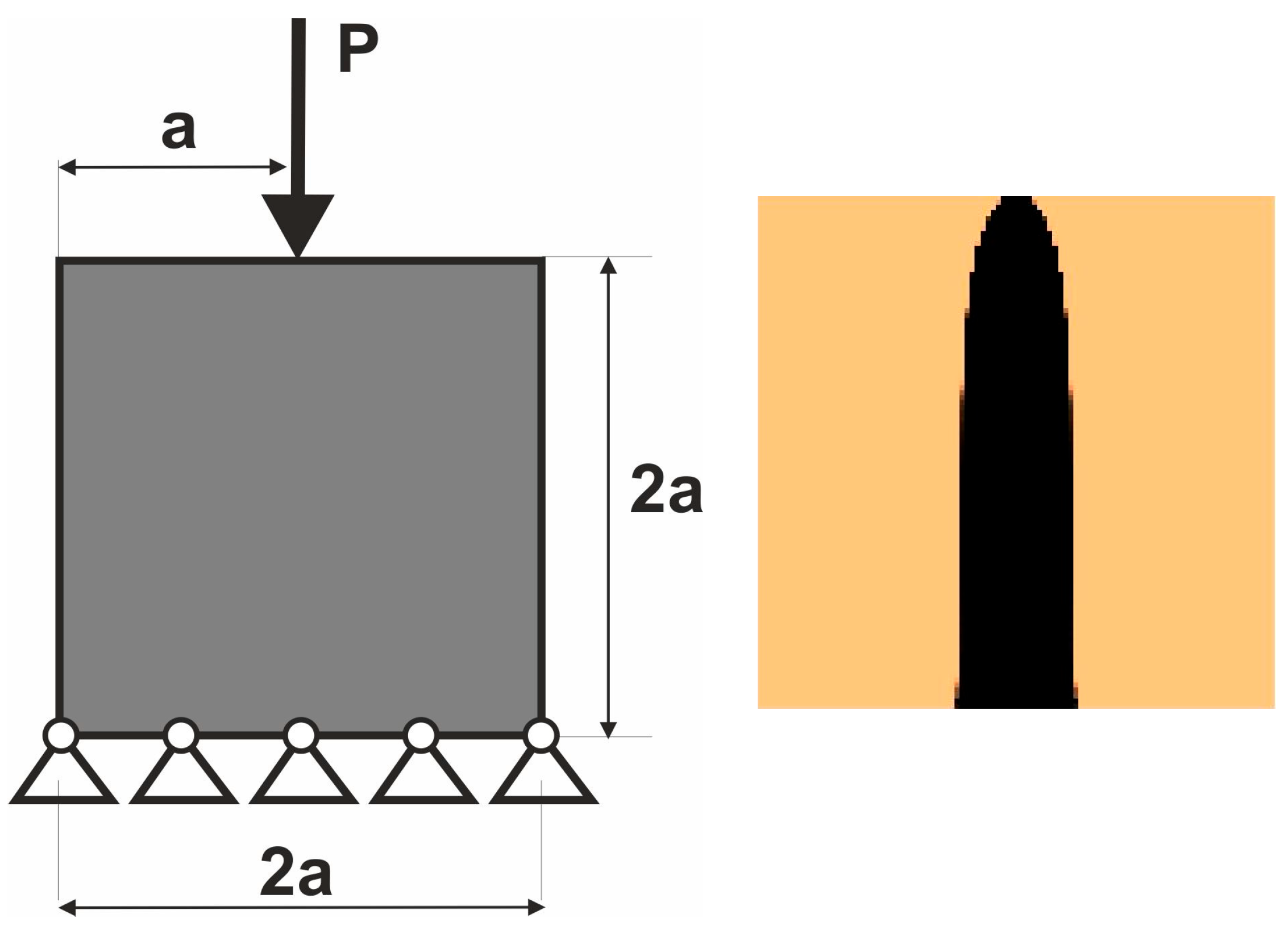
Figure 1. The introductory example: the structure under a single deterministic load (left); the final topology for the structure under a single deterministic load (right).
Applsci 15 12294 g001
Figure 2. Multiple load cases mimicking the load applied at randomly selected positions, conceptual diagram.
Applsci 15 12294 g002
Figure 3. The square structure under load applied at randomly selected positions (left) and under the deterministic Equivalent Load Scheme ELS, δ = Δ/4, conceptual diagram (right).
Applsci 15 12294 g003
Figure 4. The square structure under load applied at randomly selected positions (left) and under the deterministic Equivalent Load Scheme ELS, δ = Δ/4 (right).
Applsci 15 12294 g004
Figure 5. Random load positions s i selected within the range ,   s i = ( 2 r 1 ) (left) and obtained topology (right).
Applsci 15 12294 g005
Figure 6. A pair of loads, each applied in the middle of the load position range , δ = 2   (left) and obtained topology (right).
Applsci 15 12294 g006
Figure 7. The 4-load ELS, δ = 4 (left), and obtained topology (right).
Applsci 15 12294 g007
Figure 8. The 6-load ELS, δ = 6 (left), and obtained topology (right).
Applsci 15 12294 g008
Figure 9. The test structure 1 under a single deterministic load, a = 100 mm.
Applsci 15 12294 g009
Figure 10. The test structure 1 under a load applied at randomly selected positions [54].
Applsci 15 12294 g010
Figure 11. The test structure 1 under the Equivalent Load Scheme ELS = [P11, P12, P13, P14].
Applsci 15 12294 g011
Figure 12. The structure topology for the 4-load Equivalent Load Scheme ELS.
Applsci 15 12294 g012
Figure 13. The test structure 1 under a load applied at randomly selected positions with marked contours.
Applsci 15 12294 g013
Figure 14. The structure topology for the 4-load Equivalent Load Scheme ELS with the applied contours from above.
Applsci 15 12294 g014
Figure 15. The test structure 2 under a single deterministic load, a = 40 mm.
Applsci 15 12294 g015
Figure 16. The final topology of the test structure 2 under a load applied at randomly selected positions [54].
Applsci 15 12294 g016
Figure 17. The test structure 2 under the Equivalent Load Scheme ELS = [P11, P12, P13, P14].
Applsci 15 12294 g017
Figure 18. The test structure 2—final topology for the 4-load Equivalent Load Scheme ELS.
Applsci 15 12294 g018
Figure 19. The test structure 3 under two deterministic loads, a = 10 mm.
Applsci 15 12294 g019
Figure 20. Test structure 3—final topology for the deterministic case.
Applsci 15 12294 g020
Figure 21. Test structure 3—P1 changes its position randomly, whereas P2 remains fixed.
Applsci 15 12294 g021
Figure 22. Test structure 3—P1 changes its position randomly, whereas P2 remains fixed—final topology.
Applsci 15 12294 g022
Figure 23. Test structure 3—Equivalent Load Scheme for P1, P2 remains fixed.
Applsci 15 12294 g023
Figure 24. The test structure 3—final topology for the 4-load Equivalent Load Scheme ELS for P1, P2 remains fixed.
Applsci 15 12294 g024
Figure 25. Test structure 3—P2 changes its position randomly, whereas P1 remains fixed.
Applsci 15 12294 g025
Figure 26. Test structure 3—P2 changes its position randomly, whereas P1 remains fixed—final topology.
Applsci 15 12294 g026
Figure 27. Test structure 3—Equivalent Load Scheme for P2, P1 remains fixed.
Applsci 15 12294 g027
Figure 28. The test structure 3—final topology for the 4-load Equivalent Load Scheme ELS for P2, P1 remains fixed.
Applsci 15 12294 g028
Figure 29. Test structure 3—both P1 and P2 change their positions randomly.
Applsci 15 12294 g029
Figure 30. The test structure 3 under P1 and P2 loads applied at randomly selected positions simultaneously—final topology.
Applsci 15 12294 g030
Figure 31. The test structure 3; the Equivalent Load Schemes for both P1 and P2.
Applsci 15 12294 g031
Figure 32. The test structure 3; the Equivalent Load Schemes implemented for both P1 and P2—final topology.
Applsci 15 12294 g032
Figure 33. The test structure 4 under a single deterministic load, a = 50 mm (left), and the final topology for test structure 4 under a single deterministic load (right).
Applsci 15 12294 g033
Figure 34. The test structure 4—P changes its position randomly (left), and the final topology generated for this scenario (right).
Applsci 15 12294 g034
Figure 35. The test structure 4—Equivalent Load Scheme (left), and the final topology generated for this option (right).
Applsci 15 12294 g035
Figure 36. Dimensions of the design space—brake pedal model [mm].
Applsci 15 12294 g036
Figure 37. The brake pedal structure under 300 load cases applied at randomly selected positions—red loading.
Applsci 15 12294 g037
Figure 38. Final topology for the brake pedal under 300 load cases applied at randomly selected positions.
Applsci 15 12294 g038
Figure 39. The brake pedal structure under the Equivalent Load Scheme.
Applsci 15 12294 g039
Figure 40. Final topology for the brake pedal under the Equivalent Load Scheme (ELS).
Applsci 15 12294 g040
Figure 41. Dimensions of the design space—lever arm model [mm] and isometric view.
Applsci 15 12294 g041
Figure 42. The lever arm structure under 300 load cases applied at randomly selected positions—red loading.
Applsci 15 12294 g042
Figure 43. Final topology for the lever arm model under 300 load cases applied at randomly selected positions.
Applsci 15 12294 g043
Figure 44. The lever arm structure under the Equivalent Load Scheme.
Applsci 15 12294 g044
Figure 45. Final topology for the lever arm structure under the Equivalent Load Scheme (ELS).
Applsci 15 12294 g045
Table 1. The comparison of compliance values for the test structures.
StructureCompliance: Multi-Load, StochasticCompliance: ELSPercentage Difference
Test structure 126.9596 Nmm26.9634 Nmm0.01%
Test structure 221.3801 Nmm21.3098 Nmm0.33%
Test structure 3 (P1)30.9170 Nmm30.7509 Nmm0.54%
Test structure 3 (P2)28.8550 Nmm28.7781 Nmm0.27%
Test structure 3 (P1 + P2)31.6918 Nmm31.1125 Nmm1.83%
Test structure 416.1655 Nmm16.0927 Nmm0.45%
Brake pedal13,958.7614 Nmm14,004.6986 Nmm0.33%
Lever arm (3D)6.8320 Nmm6.6736 Nmm2.3%
Disclaimer/Publisher’s Note: The statements, opinions and data contained in all publications are solely those of the individual author(s) and contributor(s) and not of MDPI and/or the editor(s). MDPI and/or the editor(s) disclaim responsibility for any injury to people or property resulting from any ideas, methods, instructions or products referred to in the content.