Article

Damping Optimization Design of Plant Fiber-Reinforced Composites for Subway Interior Structures

by
Songli Tan
1,
Andong Cao
1,
Zhen Zhang
1,2,3,* and
Qian Li
1,2,3,*
1
School of Aerospace Engineering and Applied Mechanics, Tongji University, Shanghai 200092, China
2
Key Laboratory of AI-Aided Airworthiness of Civil Aircraft Structures, Civil Aviation Administration, Tongji University, Shanghai 200092, China
3
Shanghai Institute of Aircraft Mechanics and Control, 100 Zhangwu Road, Yangpu District, Shanghai 200092, China
*
Authors to whom correspondence should be addressed.
Appl. Sci. 2025, 15(22), 12281; https://doi.org/10.3390/app152212281
Submission received: 19 October 2025 / Revised: 9 November 2025 / Accepted: 18 November 2025 / Published: 19 November 2025
(This article belongs to the Special Issue Structural Dynamics and Vibration)

Featured Application

This work provides a design blueprint for advanced composite panels aimed at creating quieter, lighter, and more sustainable transportation systems. We demonstrate a novel methodology for optimizing carbon/flax fiber hybrid composites specifically for subway interior structures, achieving an exceptional balance between structural integrity and noise reduction. The resulting hybrid composites not only fulfill their essential load-bearing role but also actively reduce cabin noise and vibration, significantly enhancing passenger comfort. This integrated design philosophy, which combines structural and functional requirements, is readily applicable to other sectors, including the automotive and aerospace industries, for creating next-generation multifunctional components.

Abstract

The optimization of material design for subway interior structure is crucial for noise reduction and sustainability. Plant fiber-reinforced composites (PFRCs) used as interior structures offer both adequate load-bearing capacity and vibration reduction. In this study, a hybrid fiber technique was employed, integrating the Hashin failure criterion and complex eigenvalue method to investigate bending and damping performances of five distinct carbon/flax fiber-reinforced epoxy composite (CFFRC) stacking sequences (C80, C20F20C20, F15C20F15, F10C10F10C10F10, and F40) of an interior structure. The CFFRCs were fabricated via a hot press platen process with a consistent 60% overall fiber volume fraction. The experimental modal behaviors (damping ratios, frequencies, and mode shapes) were clarified by vibration tests using a non-contacting 3D Scanning Laser Doppler Vibrometer. The results revealed that hybrid composites can effectively balance the mechanical and damping properties. Hybrid composites with the flax fiber positioned in the outermost layer demonstrated superior damping performances. The optimal hybrid composite (F10C10F10C10F10) achieved a first-order modal damping ratio of 0.75% (numerically), which is significantly higher than the 0.30% observed for pure carbon fiber composites (C80). The numerical model’s validity was confirmed by a strong correlation with experimental results. It provides valuable parameters for designing safe and reliable subway interior structures, integrating load-bearing and damping capabilities.

1. Introduction

With the development of urban rail transportation, the number of subway vehicles has increased, leading to an escalation in both noise pollution and energy consumption associated with subway operations. Addressing these challenges through material selection for subway vehicles has become a critical concern in the industry [1]. Traditionally, subway interior structures primarily utilize materials like aluminum alloys, steel, or conventional fiberglass-reinforced polymers (FRPs). While these materials satisfy essential load-bearing requirements, they often lack optimal damping capabilities to effectively mitigate cabin noise and vibration, or they present sustainability challenges [2,3]. An effective approach to address these limitations is the selection of advanced composite materials. Conventional synthetic fiber-reinforced composites (e.g., pure carbon or glass fiber-reinforced composites) offer superior strength but come with high costs and poor environmental footprints [4]. Therefore, the selection of materials that can simultaneously enhance structural integrity, damping, and environmental sustainability is a critical industry concern. Plant fibers possess several key advantages, such as high specific strength and modulus, low density, and cost-effectiveness, as well as eco-friendly and globally renewable characteristics [5]. By employing plant fiber-reinforced composites (PFRCs) in subway interior structures, it is possible to enhance train speed and energy efficiency while reducing wear and impact between wheels and rails. Moreover, the vibration resistance and noise prevention of the train can be improved, ultimately reducing the overall life cycle cost of the vehicle [6,7].
Hybrid composites exhibit significant advantages over single fiber-reinforced composites, especially in terms of mechanical properties [8,9]. Pinto et al. [8] experimentally investigated the flexural, damping, and impact properties of carbon and hemp fiber-reinforced epoxy resin hybrid composites, with fiber volume fraction ranging from 53.2% to 53.8%. Tests for three-point bending, interlaminar shear, damping (free vibration test based on logarithmic decrement), and impact were conducted to determine the effects of the hemp fiber’s stacking position on the hybrid composites’ mechanical performance. It was found that the hybrid composites demonstrated a balanced combination of the absorbed energy in both flexural and dynamic conditions when the hemp layers are placed on the laminate top side. Significant improvements in flexural modulus, absorbed energy, and damage extension after impact were achieved by placing the hemp layers close to the neutral axis. The hybridization process had a notable impact on the flexural response by modifying the failure mechanism, which could be attributed to the combination of the brittle failure of carbon and the smoother, gradual deformation of the hemp fibers. Liu et al. [9] assessed the mechanical properties and durability in harsh environments of hybrid flax and glass fiber-reinforced plastic composites using a universal testing machine. The hybrid composites with the layup of [G2/F2]s exhibited the best bending and shear performance after hygrothermal aging and thermal stability performance, achieving the highest storage modulus values.
Excellent damping performances of PFRCs were demonstrated in our previous study [10]. Compared to man-made fibers with single chemical composition and microstructure, plant fibers possess complex chemical composition (i.e., cellulose, lignin, hemicellulose, pectin, and waxes) and hierarchical and lumen structure [11], which introduced a novel damping mechanism in PFRCs. Our previous work [10] has established that the superior damping in PFRCs stems from their unique multiscale structure. Unlike man-made fibers, plant fibers feature a complex hierarchy, from the cellular level with its lumen to the microfibrillar sub-layers. These inherent interfaces create multiple pathways for energy dissipation through mechanisms like interfacial friction, which are not present in man-made fibers, thus granting PFRCs excellent vibration-damping capabilities. Specifically, for unidirectional laminates, the damping ratio of PFRCs at 50 Hz was found to be up to seven times higher than that of carbon fiber-reinforced composites (CFRCs). Despite these advantages, PFRCs face challenges due to the hydrophilic nature of the fibers clashing with the hydrophobic polymer matrix, resulting in poor interfacial adhesion. Furthermore, the fibers’ hygroscopic behavior leads to dimensional instability upon moisture absorption, which can cause internal stresses and degrade long-term mechanical properties. Addressing these limitations requires advanced design and predictive strategies [12,13]. The damping properties of hybrid composites have been initially explored by several researchers [14,15,16]. Assarar et al. [14] employed the impulse technique to evaluate the effects of stacking sequences and hybridization on the damping properties of twill carbon/flax fiber-reinforced epoxy composites (CFFRCs). They found that the damping properties of hybrid composites improved with the introduction the flax fibers. Li et al. [15] revealed that the position of the flax fiber layer played a crucial role in the damping properties of CFFRCs. Ben et al. [16] indicated that the damping ratio and loss factor of unidirectional CFFRCs relied on the fiber orientation and the volume content of flax and carbon fibers. However, the detailed modal analysis of hybrid composite structures had not been clearly illustrated yet via experimental and numerical methods.
Motivated by the need to develop multifunctional and sustainable materials that overcome the trade-off between high structural performance and damping capacity, this study presents a novel, integrated methodology for the stacking sequence optimization of CFFRCs specifically for subway interior structures. Firstly, a finite element (FE) model integrating laminate theory, the Hashin failure criterion, and the complex eigenvalue method was developed to calculate the bending and damping properties of CFFRC interior structures under five different stacking sequences. Then, the experimental modal behaviors (modal damping ratios, modal frequencies, and vibration mode shapes) of CFFRC interior structures with the optimal stacking sequence were clarified by vibration tests using a non-contacting 3D Scanning Laser Doppler Vibrometer (SLDV). Finally, a structurally and functionally integrated optimization design of the CFFRC interior structure was achieved. It is meaningful to offer essential parameters for designing subway interior structures that are both safe and efficient.

2. Materials and Methods

2.1. Materials

The unidirectional flax fabrics/epoxy prepreg (UD110, 50% epoxy by total weight) were purchased from Eco-Technilin, France, with an areal density of 220 g∙m−2. The unidirectional carbon fiber/epoxy prepreg (T300/7901, USN15000-7901-33%) was purchased from Guangwei Composites Co., Ltd., Weihai, China, with an areal density of 150 g∙m−2. Both materials utilized unidirectional continuous fibers. All prepregs were stored under controlled-humidity conditions to maintain the factory-specified low moisture content of the hygroscopic natural fibers prior to manufacturing.

2.2. Numerical Analysis

The subway interior carbon/flax fiber hybrid composite of Kunming Metro Line 1, along with its geometric model, is depicted in Figure 1a [17]. FE models for analysis of damping and bending properties of CFFRC interior structures are, respectively, illustrated in Figure 1b,c.

2.2.1. FE Model for Analysis of the Damping Properties

The damping ratio varies with vibration frequency, exhibiting a strong frequency dependence. Based on the principle of extended elastic–viscoelastic correspondence, the complex eigenvalue equation for the damping vibration system is expressed in Equation (1) [18]:
( [ K ] ( ω ( r ) ) 2 [ M ] ) { ϕ } ( r ) = { 0 }
where [ K ] is the complex stiffness matrix, [ M ] is the total mass matrix of the laminate, and ( ω ( r ) ) 2 and { ϕ } ( r ) are the r-th order complex eigenvalues and eigenvectors, respectively.
The modal damping ratio η i for each mode is then extracted from the complex eigenvalue ( ω ) 2 by taking the ratio of its imaginary and real parts, as shown in Equation (2):
η i = Im ( ( ω ) 2 ) / Re ( ( ω ) 2 )
The basic material properties required for the FE simulation are given in Table 1. Table 2 illustrates the number of plies and the fiber stacking sequences for the laminate configurations. The black circle represents a ply of CFRCs and white circle represents a ply of FFRCs. The single-ply thickness of CFRCs was 0.125 mm, while the single-ply thickness of flax fiber-reinforced composites (FFRCs) was 0.25 mm, both with a fiber orientation of 0°. The overall fiber volume fraction remains consistent at 60% across all stacking sequences. At a frequency of 80 Hz, the longitudinal, transverse, and in-plane shear damping ratios were measured as 0.07, 0.34, and 0.35% for CFRCs and 0.50, 1.13, and 1.01% for FFRCs, respectively [10,19]. To capture the frequency-dependent viscoelastic behavior of the composites, the complex eigenvalue method based on laminate theory was implemented through a user-defined material subroutine (UMAT) in the FE model. Modal parameters were determined using the frequency and complex frequency analysis steps within the simulation software. The Lanczos eigensolver was selected for its efficiency in extracting the modes of the structure. Boundary conditions were applied in the initial state, with the nodes at the top corners fully fixed. The laminates were all meshed using eight-node brick elements (C3D8). After mesh sensitivity analysis, an element size of 1 × 1 mm was selected.

2.2.2. FE Model for Analysis of the Bending Properties

Based on the Hashin failure criterion, four kinds of failure modes, including fiber tension, fiber compression, matrix tension, and matrix compression, were introduced to simulate the initiation of material degradation at a given point [20,21]. The damage parameters required for the simulation were provided in Table 3. The element type was selected as the four-node reduced continuous shell element (S4R), with an element size of 1 × 1 mm, resulting in a total of 33,560 elements. Three translational degrees of freedom at both sides were restricted to simulate the real constraints for the subway interior structure. Displacement transfer during the analysis was facilitated by using a discrete rigid cylinder, on which a 2 mm displacement load was applied along the centerline of the surface. A general contact was set between the discrete rigid cylinder and the surface of the subway interior structure, with a tangential friction coefficient of 0.4. Dynamic explicit analysis was employed for the FE calculation.

2.3. Experimental

2.3.1. Preparation of the Composites

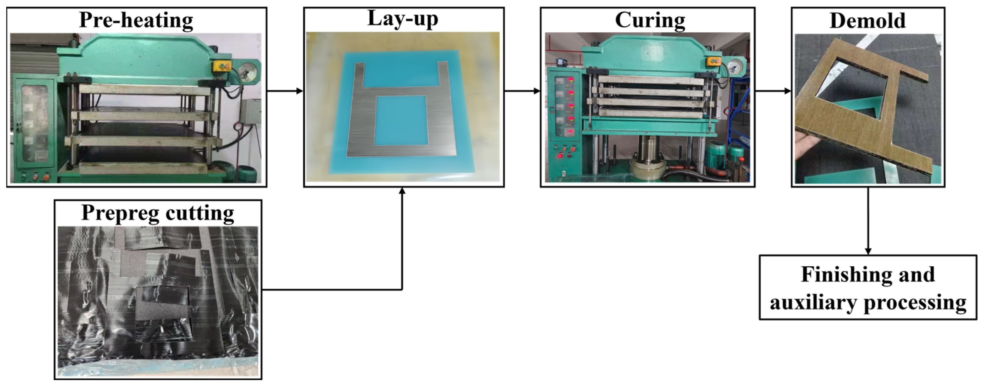
The hybrid composite interior structure with the optimal stacking sequence was manufactured using a hot press platen process, as shown in Figure 2. The specimen was cured under a pressure of 4 MPa and a temperature of 130 °C for 2 h, followed by cooling to room temperature in the oven. The dimensions were identical to those of the FE model, with a total thickness of 10 mm and an overall fiber volume content of 60%.

2.3.2. Vibration Tests

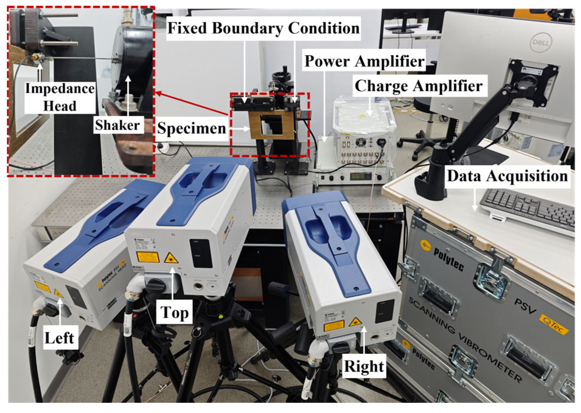
The first ten order mode shapes of the prepared CFFRC structures were characterized through vibration tests using a non-contact 3D SLDV. The 3D SLDV (Polytec, Waldbronn, Germany) operates based on the Doppler principle and consists of three independent SLDV heads (top, left, and right). The experimental setup for the 3D vibration measurement of the specimen is exhibited in Figure 3. The top sides of the specimen were clamped to establish fixed boundary conditions. The modal shaker (DH40050), power amplifier (DH5871), and charge amplifier (DH5862) were provided by Donghua Testing Technology Co., Ltd., Taizhou, China. As shown in the top left corner of Figure 3, the modal shaker was fixed to a large, heavy table and attached to the opposite side of the specimen via an impedance head. A power amplifier was connected to the modal shaker to provide adequate energy input. A charge amplifier, which converts coulombs to volts, was connected to the data acquisition system of SLDV. The instantaneous velocities of the specimen along its line of sight were captured by each laser transducer. The resonances were identified by selecting the peaks in the frequency spectrum, and the corresponding mode shapes were visualized under broad frequency band excitation.

3. Results and Discussion

3.1. Effects of Stacking Sequences on the Damping Properties of CFFRC Structures

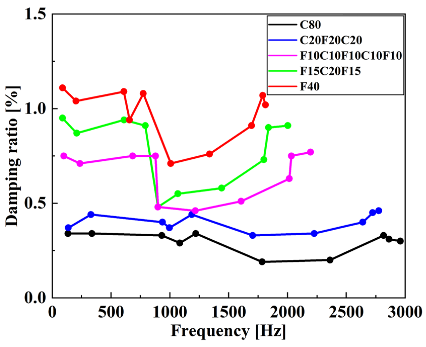
Variations in numerical damping ratios with the first ten modal frequencies for the CFFRC structures with different stacking sequences as illustrated in Figure 4. As shown in Figure 4, pure CFRCs exhibited the lowest damping ratio, while pure FFRCs possessed the highest damping ratio. It can be attributed to the hierarchical structure and viscoelastic behaviors of flax fibers, creating additional pathways for energy dissipation at the interface between each cell wall layer and the micro-fibrillated sub-layers. The stacking sequence of carbon or flax fiber had a considerable impact on the damping ratio of the hybrid composites. The damping ratio of the CFFRC structure could be effectively enhanced by incorporating flax fibers into the hybrid composites, with the greatest improvement observed by placing the flax fibers in the outermost layer, which is consistent with the findings reported in the literature [8]. The reason was that the outer layers of the CFFRC structure experienced the maximum strain during vibration, leading to great internal deformation and more effective energy dissipation through hierarchical interfacial friction. The outermost layers played a dominant role in the overall dynamic response of the structure. High damping capacity of the outer layers could absorb and dissipate effective vibrational energy before it propagates deep into the structure. As a result, the damping energy generated by the outer layers could significantly reduce the vibrations of the entire CFFRC structure, thus improving the overall damping ratio of the structure. Therefore, the damping properties of the CFFRC structure with the stacking sequence of F15C20F15 and F10C10F10C10F10 were superior to those of C20F20C20.
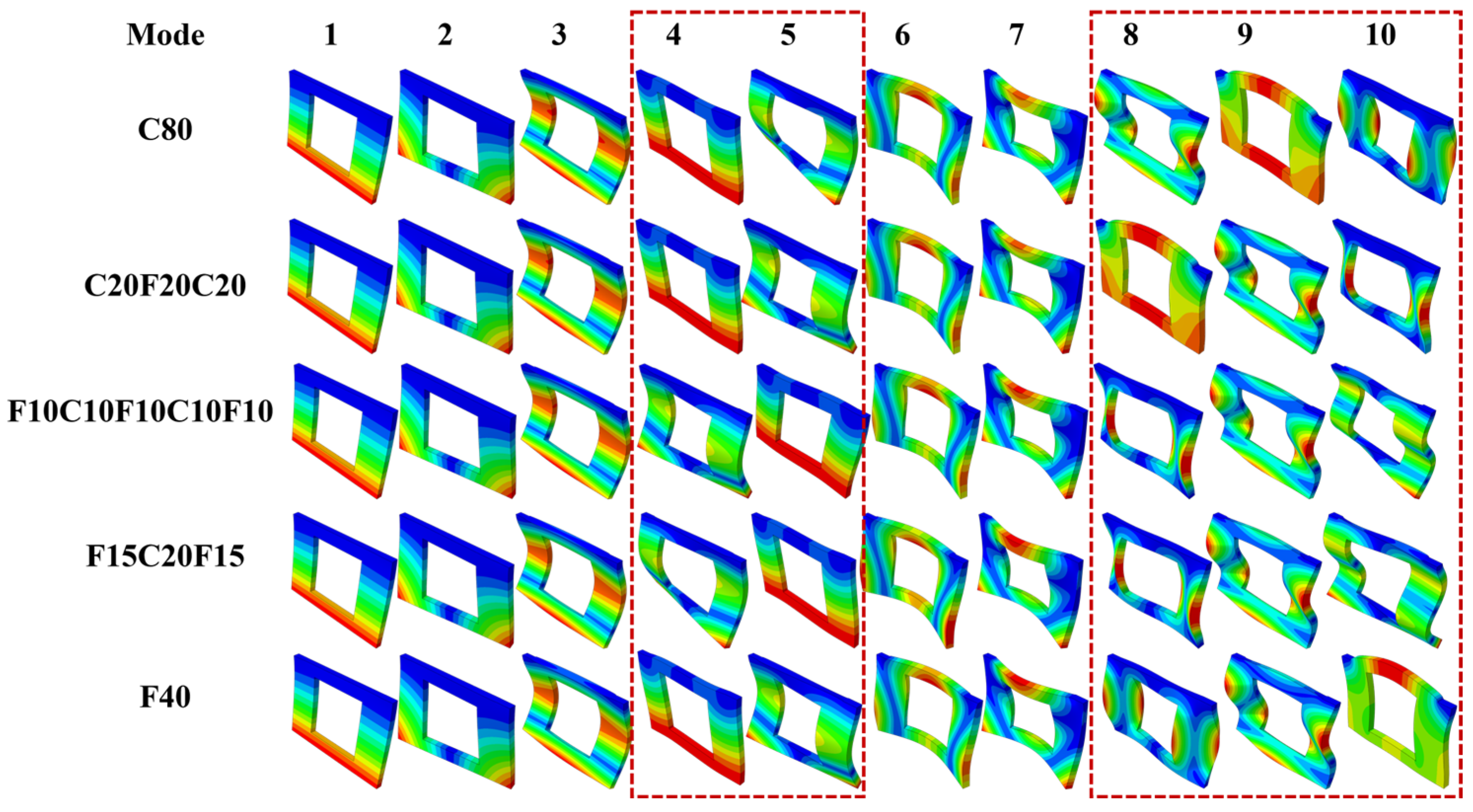
The first ten vibration mode shapes for the CFFRC structures with different stacking sequences were simulated and presented in Figure 5. It could be observed that the mode shapes of the composite structures at the 4th, 5th, 8th, 9th, and 10th modes varied depending on the stacking sequences. High-order mode shapes were primarily affected by the stacking sequence. The introduction of the flax fibers in CFRCs caused the 8th mode to be more difficult to excite. When carbon fiber as the outer layer was substituted with flax fiber for the hybrid composites, the 10th mode appeared earlier than the 8th mode. This could be attributed to distinct damping mechanisms of flax fiber layers at different vibration frequencies [22,23,24,25]. Friction within and between the cell wall layers and micro-fibrillated sub-layers contributed to energy dissipation at small deformations. The time for energy dissipation increased at low vibration frequencies, leading to the enhanced damping ratios of CFFRC structures, whereas friction within and between the twisted flax yarns became the primary mechanism for energy dissipation at large deformations. A short period for energy dissipation occurred at high vibration frequencies, reducing the damping effectiveness.

3.2. Effects of Stacking Sequences on the Bending Properties of CFFRC Structures

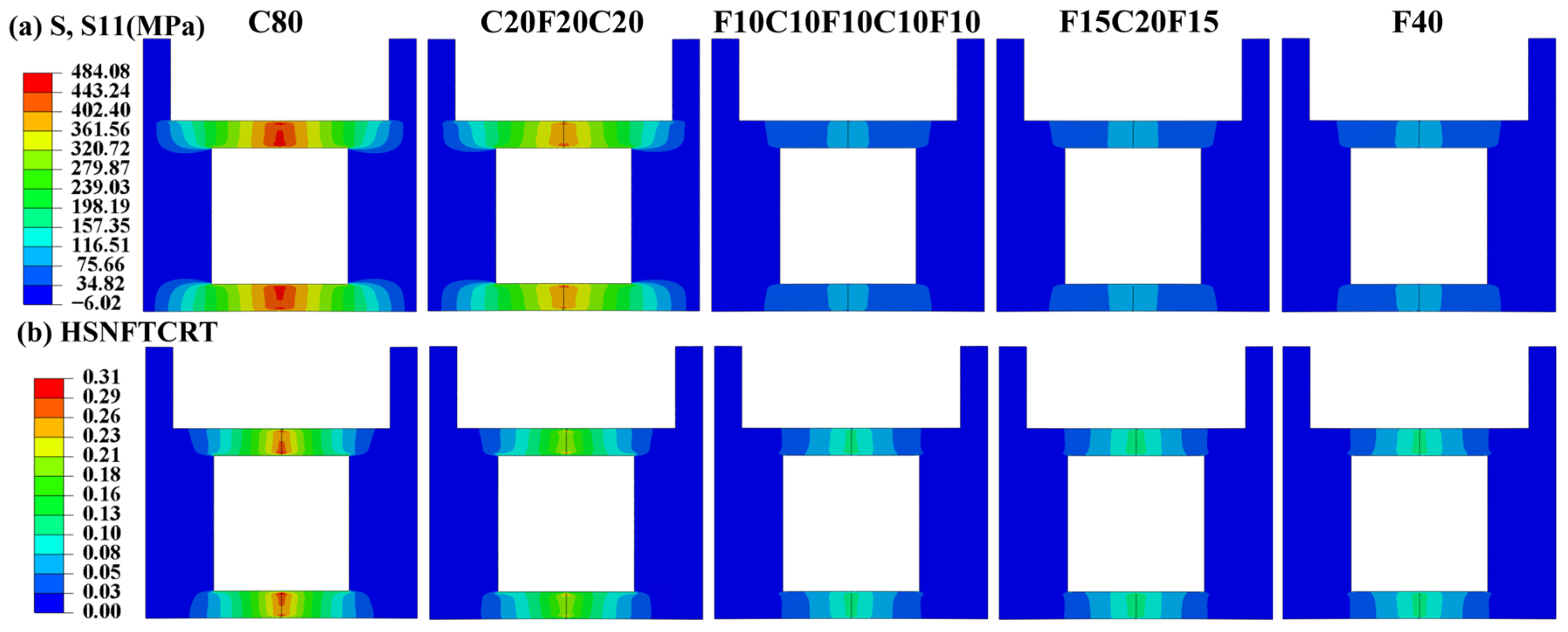
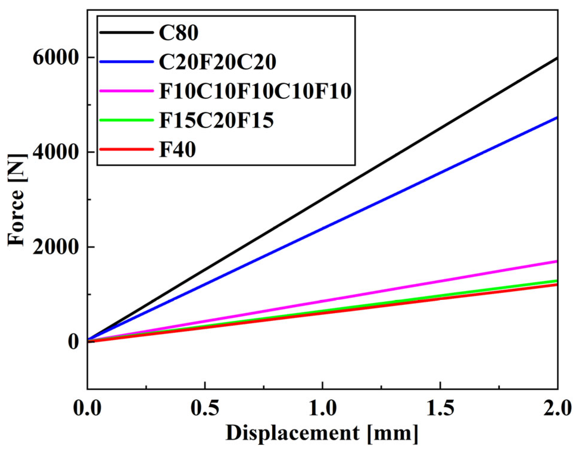
The in-plane stress distributions along the fiber direction and the initiation factor of fiber tensile damage of the bottom layer under bending load for the CFFRC structures with five different stacking sequences were fully analyzed and illustrated in Figure 6. It could be seen that the stacking sequences of the hybrid composites had a significant influence on the bending strength. As a number of flax fiber layers were positioned close to the outer layer, the bending strength decreased, which could be attributed to the maximum compressive and tensile stress being, respectively, observed at the upper and lower layers of the CFFRCs structures under bending load, with relatively low shear stress. The maximum shear stress occurred on the fiber layers at the middle position, along with low compressive and tensile stress. When carbon fiber as the outer layer was substituted with flax fiber, the flax fiber layer was unable to sustain a high bending load and failed earlier due to low strength and modulus. The force–displacement curves at loading direction for the CFFRC structures with different stacking sequences are displayed in Figure 7. It can be observed that the values of force for the CFFRC structures with the stacking sequence of C20F20C20 were significantly higher than those for the other two hybrid composites. Among the three kinds of stacking sequences with the flax fiber layer positioned at the outermost layer, the CFFRC structure with the stacking sequence of F10C10F10C10F10 exhibited the highest bending properties.

3.3. Mechanisms on Structural and Functional Integrated Optimization Design of CFFRC Structures

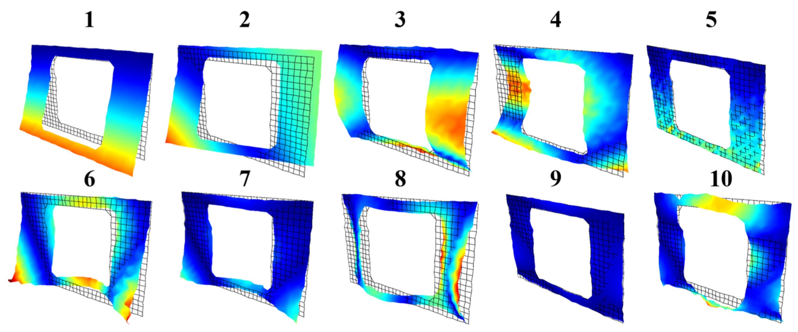
Pure CFRCs had high bending properties but low damping properties, and an opposite trend was presented for pure FFRCs, which is consistent with the findings of Ben et al. [16]. For the CFFRC structures with the flax fiber as the outer layer, a large bending deformation was observed compared to those with the flax fiber as the inner layer. High interfacial frictional dissipation within the flax fibers contributed to the high damping performances of the structures [26]. Therefore, the optimal stacking sequence for achieving the desired mechanical and damping properties in the subway interior panel structure was the hybrid composite with the stacking sequence of F10C10F10C10F10. Mode shapes were defined in relation to the natural frequencies of the structure and did not change with external excitation, while the forced response of the structure subjected to excitation at given frequencies was referred to as the Operational Deformation Shape (ODS). The resonant behavior of the structure could be characterized by the mode shapes, whereas both resonant and non-resonant vibration states could be described by the ODS. When the excitation frequency is equal to the r-th natural frequency, the ODS of the structure’s forced response is primarily dominated by the vibration of the r-th mode. In this case, it can be assumed that the ODS represents the mode shape of the structure at the r-th mode. To clarify the damping optimization mechanisms of CFFRC structures, the first ten vibration mode shapes for the interior structures with the stacking sequence of F10C10F10C10F10 were measured and demonstrated in Figure 8. A significant agreement between the experimental first seven mode shapes and those derived from the established model was achieved. Since the ODS could be affected by variations in external excitation, the vibration of the r-th mode shape depended on the ODS of the CFFRC structure when the excitation frequency coincided with the r-th natural frequency. The mode shape of the structure at the r-th mode was assumed to be described by the ODS. High-order mode shapes with bending and torsional coupling components became increasingly complex and pronounced. The experimental first ten order modal damping ratios were derived from the Fourier transform of the frequency response function by using a broad frequency band input. The comparison between numerical and experimental results of the first ten order modal frequencies and damping ratios is listed in Table 4. Hierarchical interlaminar interfaces for the interior structures with the stacking sequence of F10C10F10C10F10 provided additional channels for effective energy dissipation, leading to excellent damping performances.

4. Conclusions

The structural and damping optimization designs for the subway interior structure with carbon/flax fiber-reinforced epoxy composites (CFFRCs) were investigated in this study. The main findings were concluded as follows:
(1)
The effects of the stacking sequences on the bending and damping properties of CFFRC structures were evaluated by developing a finite element (FE) model integrating laminate theory, the Hashin failure criterion, and the complex eigenvalue method. The stacking sequence of carbon or flax fiber had a considerable impact on the damping ratio of the CFFRC structure, with the greatest improvement by placing the flax fibers in the outermost layer, whereas the bending strength decreased as the number of flax fiber layers positioned close to the outer layer. The balance between the damping and bending properties should be considered for structural design. The CFFRC structure with the stacking sequence of F10C10F10C10F10 exhibited balanced damping and bending properties.
(2)
Mechanisms of load-bearing and damping functional integrated optimization design of CFFRC structures were clarified. High damping capacity of the outer layers could absorb and dissipate effective vibrational energy before it propagates deep into the structure. The hierarchical structure and viscoelastic behaviors of flax fibers created additional pathways for energy dissipation at the interface between each cell wall layer and the micro-fibrillated sub-layers. The maximum compressive and tensile stresses were observed at the upper and lower layers of the CFFRC structures under bending load, with relatively low shear stress. When flax fiber as the outer layer was substituted with carbon fiber, the carbon fiber layer could sustain a high bending load.
(3)
The experimental modal behaviors (modal damping ratios, modal frequencies, and vibration mode shapes) of CFFRC structures with the optimal stacking sequence were identified by employing a non-contacting 3D Scanning Laser Doppler Vibrometer (SLDV) in vibration tests. The effects of the stacking sequences on the mode shapes tended to primarily occur in high-order modes. A significant agreement between the experimental first seven mode shapes and those derived from the established model was achieved. The findings provided essential parameters for designing subway interior structures that are both safe and reliable.
The current findings are specifically confined to the non-standard geometry of the subway interior structure with unidirectional (0°) plies, thus limiting generalized applicability. Furthermore, the mechanical bending results were based solely on simulation (the Hashin failure criterion) without experimental validation due to the complex panel geometry. Future work will focus on designing customized fixtures for experimental bending validation, exploring multi-directional layups to improve structural performance, and conducting an expanded experimental campaign to provide statistical variability for damping properties.

Author Contributions

Conceptualization, Z.Z.; methodology, S.T. and A.C.; software, S.T., A.C. and Z.Z.; validation, S.T., A.C., Z.Z. and Q.L.; formal analysis, S.T. and Z.Z.; investigation, S.T.; resources, Z.Z. and Q.L.; data curation, S.T. and Z.Z.; writing—original draft preparation, S.T.; writing—review and editing, Z.Z. and Q.L.; visualization, S.T., Z.Z. and Q.L.; supervision, Z.Z. and Q.L.; project administration, S.T. and Q.L.; funding acquisition, Z.Z. and Q.L. All authors have read and agreed to the published version of the manuscript.

Funding

This research was funded by the Natural Science Foundation of Shanghai (No. 23ZR1466100), the National Natural Science Foundation of China (NSFC) Young Scientist Fund (No. 12302183), the Young Elite Scientists Sponsorship Program by CAST (2023QNRC001), the Shanghai Gaofeng Project for University Academic Program Development, and it was supported by the Fundamental Research Funds for the Central Universities from Tongji University.

Institutional Review Board Statement

Not applicable.

Informed Consent Statement

Not applicable.

Data Availability Statement

The original contributions presented in this study are included in the article. Further inquiries can be directed to the corresponding authors.

Conflicts of Interest

The authors declare no conflicts of interest.

Abbreviations

The following abbreviations are used in this manuscript:
PFRCsPlant fiber-reinforced composites
CFFRCsCarbon/flax fiber-reinforced epoxy composites
FRPsFiberglass-reinforced polymers
FEFinite element
SLDVScanning Laser Doppler Vibrometer
CFRCsCarbon fiber-reinforced composites
FFRCsFlax fiber-reinforced composites
UMATUser-defined material subroutine
ODSOperational Deformation Shape

References

  1. Saeedi, A.; Motavalli, M.; Shahverdi, M. Recent Advancements in the Applications of Fiber—Reinforced Polymer Structures in Railway Industry—A Review. Polym. Compos. 2024, 45, 77–97. [Google Scholar] [CrossRef]
  2. Chango, I.V.L.; Chen, J. Numerical and Statistical Evaluation of the Performance of Carbon Fiber-Reinforced Polymers as Tunnel Lining Reinforcement during Subway Operation. Buildings 2022, 12, 1913. [Google Scholar] [CrossRef]
  3. Navaratnam, S.; Selvaranjan, K.; Jayasooriya, D.; Rajeev, P.; Sanjayan, J. Applications of Natural and Synthetic Fiber Reinforced Polymer in Infrastructure: A Suitability Assessment. J. Build. Eng. 2023, 66, 105835. [Google Scholar] [CrossRef]
  4. Manso-Morato, J.; Hurtado-Alonso, N.; Revilla-Cuesta, V.; Skaf, M.; Ortega-López, V. Fiber-Reinforced Concrete and Its Life Cycle Assessment: A Systematic Review. J. Build. Eng. 2024, 94, 110062. [Google Scholar] [CrossRef]
  5. Zhang, Z.; Cai, S.; Li, Y.; Wang, Z.; Long, Y.; Yu, T.; Shen, Y. High Performances of Plant Fiber Reinforced Composites—A New Insight from Hierarchical Microstructures. Compos. Sci. Technol. 2020, 194, 108151. [Google Scholar] [CrossRef]
  6. Muneer Ahmed, M.; Dhakal, H.N.; Zhang, Z.Y.; Barouni, A.; Zahari, R. Enhancement of Impact Toughness and Damage Behaviour of Natural Fibre Reinforced Composites and Their Hybrids through Novel Improvement Techniques: A Critical Review. Compos. Struct. 2021, 259, 113496. [Google Scholar] [CrossRef]
  7. Li, M.; Pu, Y.; Thomas, V.M.; Yoo, C.G.; Ozcan, S.; Deng, Y.; Nelson, K.; Ragauskas, A.J. Recent Advancements of Plant-Based Natural Fiber–Reinforced Composites and Their Applications. Compos. Part B Eng. 2020, 200, 108254. [Google Scholar] [CrossRef]
  8. Pinto, F.; Boccarusso, L.; De Fazio, D.; Cuomo, S.; Durante, M.; Meo, M. Carbon/Hemp Bio-Hybrid Composites: Effects of the Stacking Sequence on Flexural, Damping and Impact Properties. Compos. Struct. 2020, 242, 112148. [Google Scholar] [CrossRef]
  9. Liu, Z.; Wang, H.; Yang, L.; Du, J. Research on Mechanical Properties and Durability of Flax/Glass Fiber Bio-Hybrid FRP Composites Laminates. Compos. Struct. 2022, 290, 115566. [Google Scholar] [CrossRef]
  10. Tan, S.; Zhang, Z.; Li, Q.; Yang, W.; Yu, T.; Li, Y. Characterization and Prediction of Frequency- and Moisture-Dependent Damping Behaviors for Hierarchical Flax Fiber Reinforced Composite Laminates. Compos. Sci. Technol. 2024, 254, 110682. [Google Scholar] [CrossRef]
  11. Li, Q.; Li, Y.; Ma, H.; Cai, S.; Huang, X. Effect of Processing Temperature on the Static and Dynamic Mechanical Properties and Failure Mechanisms of Flax Fiber Reinforced Composites. Compos. Commun. 2020, 20, 100343. [Google Scholar] [CrossRef]
  12. Karthi, N.; Kumaresan, K.; Sathish, S.; Gokulkumar, S.; Prabhu, L.; Vigneshkumar, N. An Overview: Natural Fiber Reinforced Hybrid Composites, Chemical Treatments and Application Areas. Mater. Today Proc. 2020, 27, 2828–2834. [Google Scholar] [CrossRef]
  13. Mohammed, M.; Jawad, A.J.M.; Mohammed, A.M.; Oleiwi, J.K.; Adam, T.; Osman, A.F.; Dahham, O.S.; Betar, B.O.; Gopinath, S.C.B.; Jaafar, M. Challenges and Advancement in Water Absorption of Natural Fiber-Reinforced Polymer Composites. Polym. Test. 2023, 124, 108083. [Google Scholar] [CrossRef]
  14. Assarar, M.; Zouari, W.; Sabhi, H.; Ayad, R.; Berthelot, J.-M. Evaluation of the Damping of Hybrid Carbon–Flax Reinforced Composites. Compos. Struct. 2015, 132, 148–154. [Google Scholar] [CrossRef]
  15. Li, Y.; Cai, S.; Huang, X. Multi-Scaled Enhancement of Damping Property for Carbon Fiber Reinforced Composites. Compos. Sci. Technol. 2017, 143, 89–97. [Google Scholar] [CrossRef]
  16. Ben Ameur, M.; El Mahi, A.; Rebiere, J.-L.; Abdennadher, M.; Haddar, M. Damping Analysis of Unidirectional Carbon/Flax Fiber Hybrid Composites. Int. J. Appl. Mech. 2018, 10, 1850050. [Google Scholar] [CrossRef]
  17. Li, Y.; Li, Q. Plant Fiber Reinforced Composites; Engineering Materials; Springer Nature: Singapore, 2022; pp. 220–221. [Google Scholar]
  18. He, Y.; Xiao, Y.; Liu, Y.; Zhang, Z. An Efficient Finite Element Method for Computing Modal Damping of Laminated Composites: Theory and Experiment. Compos. Struct. 2018, 184, 728–741. [Google Scholar] [CrossRef]
  19. Liu, Y.; Xiao, Y.; Zhang, Z.; He, Y. Modal damping prediction of laminated composites using elastic-viscoelastic correspond-ence principle: Theory and finite element implementation. Acta Mater. Compos. Sin. 2017, 34, 1478–1488. [Google Scholar] [CrossRef]
  20. Hashin, Z. Complex Moduli of Viscoelastic Composites—II. Fiber Reinforced Materials. Int. J. Solids Struct. 1970, 6, 797–807. [Google Scholar] [CrossRef]
  21. Wan, Y.; Liu, Y.; Hu, C.; Yao, J.; Wang, F.; Yang, B. The Failure Mechanism of Curved Composite Laminates Subjected to Low-Velocity Impact. Acta Mech. Sin. 2023, 39, 423113. [Google Scholar] [CrossRef]
  22. Duc, F.; Bourban, P.E.; Månson, J.-A.E. The Role of Twist and Crimp on the Vibration Behaviour of Flax Fibre Composites. Compos. Sci. Technol. 2014, 102, 94–99. [Google Scholar] [CrossRef]
  23. Amenini, F.; Brocail, J.; Chauvin, M.; Thuillier, S. Dynamical Properties of Flax Fibre Reinforced PA11 over a Large Frequency Range. Compos. Sci. Technol. 2019, 171, 234–243. [Google Scholar] [CrossRef]
  24. Liu, T.; Butaud, P.; Placet, V.; Ouisse, M. Damping Behavior of Plant Fiber Composites: A Review. Compos. Struct. 2021, 275, 114392. [Google Scholar] [CrossRef]
  25. Wei, D.; Nurakhmetov, D.; Spitas, C.; Aniyarov, A.; Zhang, D. Nonlinear Dynamical Analysis of Some Microelectromechanical Resonators with Internal Damping. Acta Mech. Sin. 2021, 37, 1457–1466. [Google Scholar] [CrossRef]
  26. Li, Y.; Yi, X.; Yu, T.; Xian, G. An Overview of Structural-Functional-Integrated Composites Based on the Hierarchical Microstructures of Plant Fibers. Adv. Compos. Hybrid Mater. 2018, 1, 231–246. [Google Scholar] [CrossRef]
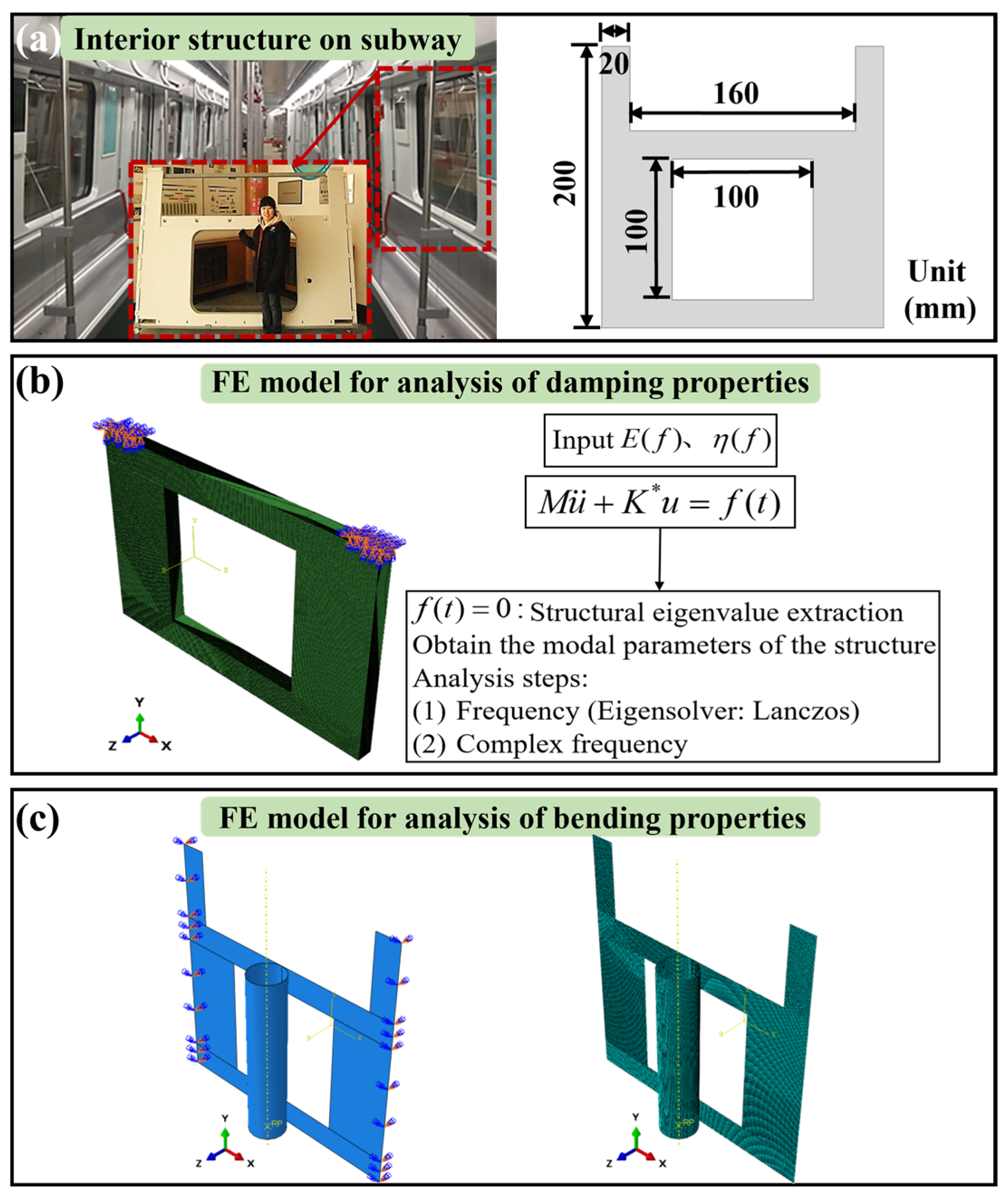
Figure 1. Schematic illustration of (a) the side panel of a railcar within the dashed box and geometric model [17], and the FE model for analysis of the (b) damping and (c) bending properties of CFFRC interior structures.
Applsci 15 12281 g001
Figure 2. Flowchart of hot press platen process.
Applsci 15 12281 g002
Figure 3. Experimental setup for the 3D vibration measurement. (The modal shaker was fixed to a large, heavy table and attached to the opposite side of the specimen via an impedance head within the dashed box).
Applsci 15 12281 g003
Figure 4. Variations in numerical damping ratios with the first ten modal frequencies for the CFFRC structures with different stacking sequences.
Applsci 15 12281 g004
Figure 5. Numerical results of the first ten vibration mode shapes for the CFFRC structures with different stacking sequences. (The different colors represent the distribution of velocity response amplitude relative to the input force, the mode shapes of the composite structures at the 4th, 5th, 8th, 9th, and 10th modes varied depending on the stacking sequences within the dashed box, and the numbers represent the modal orders).
Applsci 15 12281 g005
Figure 6. (a) In-plane stress distributions along the fiber direction (unit: MPa) and (b) initiation factor of fiber tensile damage of the bottom layer under bending load for the CFFRC structures with different stacking sequences.
Applsci 15 12281 g006
Figure 7. Numerical results of force–displacement curves for the CFFRC structures with different stacking sequences.
Applsci 15 12281 g007
Figure 8. Experimental results of the first ten vibration mode shapes for the structures with the stacking sequence of F10C10F10C10F10. (The meanings of different colors and numbers are the same as in Figure 5).
Applsci 15 12281 g008
Table 1. Material constants for the interior structures used in the FE model.
E1 (GPa)E2 (GPa)E3 (GPa)v12v13v23G12 (GPa)G13 (GPa)G23 (GPa)Density
CFRCs1608.78.70.300.300.456.56.53.251690
(kg/m3)
FFRCs322.62.60.120.120.141.41.40.71120
(kg/m3)
Table 2. Stacking sequences of carbon fiber/flax fiber-reinforced epoxy composite interior structures.
LaminatesPly Number Ratio (Flax/Carbon)Stacking Sequence
C800/80Applsci 15 12281 i001
C20F20C2020/40Applsci 15 12281 i002
F15C20F1530/20Applsci 15 12281 i003
F10C10F10C10F1030/20Applsci 15 12281 i004
F4040Applsci 15 12281 i005
Table 3. Failure criteria for the interior structures used in the FE model.
Xt (MPa)Xc (MPa)Yt (MPa)Yc (MPa)S (MPa)
CFRCs895626255237
FFRCs275192163224
Table 4. Comparison between numerical and experimental results of the first ten order modal frequencies and damping ratios.
ModeFrequency (Hz)Damping Ratio (%)
NumExpNumExp
199.3791.240.750.91
2237.24215.680.710.93
3685.03636.790.750.87
4878.73849.500.750.95
5899.91862.180.480.76
61216.61170.930.460.72
71605.31583.510.510.78
82016.11942.760.630.84
92033.81993.090.750.96
102195.52007.560.770.92
Disclaimer/Publisher’s Note: The statements, opinions and data contained in all publications are solely those of the individual author(s) and contributor(s) and not of MDPI and/or the editor(s). MDPI and/or the editor(s) disclaim responsibility for any injury to people or property resulting from any ideas, methods, instructions or products referred to in the content.