Article

Numerical Simulation of Fracture Propagation and Damage Evolution in Coal Seam Under Controlled High-Energy Shock Wave Fracturing

1
Engineering Technology Research Institute of CNPC Xibu Drilling Engineering Co., Ltd., Karamay 834000, China
2
School of Resources and Geosciences, China University of Mining and Technology, Xuzhou 221116, China
3
Key Laboratory of Coalbed Methane Resource and Reservoir Formation Process, Ministry of Education, China University of Mining and Technology, Xuzhou 221008, China
*
Authors to whom correspondence should be addressed.
Appl. Sci. 2025, 15(22), 12279; https://doi.org/10.3390/app152212279
Submission received: 10 October 2025 / Revised: 13 November 2025 / Accepted: 17 November 2025 / Published: 19 November 2025
(This article belongs to the Section Energy Science and Technology)

Abstract

Reservoir stimulation is a critical technique for the efficient development of coalbed methane (CBM), playing a significant role in improving permeability. Controlled shock wave fracturing, as an emerging stimulation method, offers advantages such as safety and high energy utilization, making it a promising candidate for CBM reservoir enhancement. Due to the substantial potential of deep CBM reservoirs, conventional physical simulations and field experiments are limited in accurately analyzing the fracturing effects. Research on the fracture propagation and damage evolution of coal rock under the influence of different geological and engineering parameters is limited, hindering the determination of key operational parameters. In this study, a coupled mathematical model of solid mechanics and damage continuum mechanics is established using the finite element method, alongside a geometric model, to investigate fracture propagation characteristics under the influence of geological and engineering factors. The core contribution of this work is a systematic numerical analysis that clarifies the controlling effects of key parameters. The main conclusions are as follows: (1) a high stress contrast (≥6 MPa) favors fracture extension along the direction of the maximum principal stress while inhibiting the expansion of the damage area; (2) the increase in the orientation of natural fissures and the angle of horizontal stress inhibits the propagation of fractures and the growth of damage area; (3) engineering parameters exert a considerable effect on fracture propagation and multiple shock cycles (≥2 times) and high peak pressure (≥250 MPa) are conducive to fracture formation; and (4) a key distinguishing feature is the formation of radioactive fractures induced by high-energy shock waves, which are beneficial for enhancing communication between rock layers and natural fractures. Compared to hydraulic fracturing, the shock wave method achieves distinctly faster fracture extension in a shorter time, highlighting its unique advantage for improving coalbed permeability and porosity. This study extends the numerical simulation research on controlled shock waves in deep coal seams, elucidates the dynamic response of fracture propagation and damage evolution under the control of geological and engineering parameters, reveals the sensitivity of key parameters to fracture extension, and provides a critical basis for the selection and optimization of operational parameters in field applications of shock wave fracturing.

1. Introduction

With the continuous growth in energy demand driven by economic development, China faces a prominent contradiction between energy supply and demand, due to the complexity of resource endowment and the weak theoretical foundation [1,2]. As an important component of unconventional natural gas, the coalbed methane (CBM) resource in coal layers deeper than 2 km is estimated to be 40.71 × 10¹² m3 [3,4]. The large-scale exploration and development of unconventional natural gas can help alleviate the tension between energy supply and demand, ensuring energy security.
As the development of unconventional natural gas deepens, traditional technologies can no longer meet the increasing production demands. Reservoir stimulation has become a crucial technology in CBM exploration and development. Fracturing technologies can improve coalbed permeability, and then, gas well production [5,6,7], and several methods have been developed, including hydraulic fracturing, non-water fracturing, acid fracturing, and explosion fracturing. However, despite the widespread application of hydraulic fracturing, issues such as proppant-induced water contamination, water resource shortages, and limited branching fractures exist [8,9]. CO2 fracturing suffers from low viscosity, poor sand-carrying capacity, and high filtration losses, making it unsuitable for deep wells and high-permeability reservoirs [10]. Acid fracturing can effectively alter the coal’s pore structure and enhance permeability, but its effectiveness is easily influenced by mineral types, acid fluids, and pore temperature [11]. Explosion fracturing can cause severe damage to the wellbore and is not suitable for coal layers with high gas content, potentially triggering gas disasters [12]. Among these methods, controlled shock wave fracturing, based on the electro-hydraulic effect, is an innovative coalbed stimulation technique that does not require injecting fluids into the reservoir. Instead, high-energy shock waves are generated using energetic materials or metal wires, creating multi-directional fractures and forming fracture networks in a short time [13]. Currently, controlled shock wave fracturing has garnered significant attention and research. In field experiments, Qiao et al. [14] established a mathematical model for coalbed dynamic response based on explosion mechanics, rock dynamics, and elasticity. This model determines the effective influence radius, and field test data showed that this technology significantly improved coalbed methane production within the affected area. An et al. [15] conducted pilot tests, identifying shock density and the fracture-enhancing operation range as key factors for improving fracturing effectiveness, and finally determining fracturing range and shock density. Wang [16] analyzed test results from over 40 coalbed wells in the South Yanchuan Block, determining that the optimal well selection criteria for controlled shock wave treatments include low coalbed fracture pressure, the presence of impurities, good gas content, and relatively high pressure coefficients. In terms of physical simulation, Wang et al. [17] conducted physical simulation experiments on different types of rocks, determining the energy storage design parameters for high-strength cement, granite, and limestone. Qiao et al. [8], using a self-constructed controlled shock wave simulation platform, found that discharge voltage and frequency play a critical role in enhancing permeability in low-permeability coal layers. Han et al. [18] performed pulse-type repeated controlled shock wave fracturing experiments under triaxial stress loading, illustrating the relationship between shock wave energy and the complexity of crack propagation. Chen et al. [19] conducted controlled shock wave pre-fracturing tests, determining that with a 3-m interval between operation points and a peak pressure of 224 MPa, performing ≥ 4 shock cycles can achieve uniform pre-fracturing within the target area.
However, since fracture initiation by shock waves results from a combination of geological conditions and shock wave operating conditions, it is challenging to simulate this process systematically in physical experiments, and field monitoring conditions are not yet suitable [20]. Meanwhile, numerical simulations, as an essential tool for studying fracture propagation mechanisms, can compensate for the high cost and poor controllability of field tests. Many scholars have carried out numerical simulations of shock wave-induced fracturing. As example, Sun et al. [21], combining a damage-permeability-deformation coupled model, analyzed the positive correlation between shock intensity and damage area, highlighting the suppressive effect of geostress on fracture propagation. Moreover, Qin et al. [20] used the discrete element method with continuum mechanics to explain the influence of loading conditions, geostress, and mechanical properties on fracturing effectiveness. Based on numerical simulations, Li [22] showed that there is an optimal range of peak pressure, shock cycles, and fracture initiation effects, with geostress having a strong inhibitory effect, and elastic modulus and tensile strength being the key mechanical parameters that affect fracturing performance.
Accordingly, given the applicability of controlled shock wave fracturing to deep CBM reservoirs and the practical difficulty and high cost of conventional physical experiments, this study employs numerical simulations to elucidate the controlling factors and the advantages of controlled high-energy shock-wave fracturing over hydraulic fracturing, and to investigate fracture propagation and damage evolution under controlled repeated high-energy shock wave loading. By using the finite element method, a solid mechanics and damage continuum mechanics coupled model is established, introducing high-energy shock wave loads to simulate the dynamic fracture propagation characteristics in coal-rock formations. The study explores the impact of geological and engineering parameters on fracture morphology and propagation paths. Through comparison with hydraulic fracturing effects and mechanisms, this research demonstrates the potential and advantages of high-energy pulse fracturing in improving reservoir stimulation, providing guidance for the application of controlled high-energy shock wave fracturing technology in efficient CBM exploration and development.

2. Numerical Simulation Model Construction

2.1. Mathematical Model and Basic Assumptions

The coal seam is primarily composed of coal matrix and fractures [23]. During the controlled repeated high-energy shock wave fracturing process, the main deformation of the coal body remains within the small deformation range. Under tensile stress, the coal exhibits tensile failure characteristics, while under compressive stress, it exhibits shear failure characteristics. Based on the rationality of coal seam damage analysis, the assumptions for the mathematical models of controlled repeated high-energy shock wave fracturing and hydraulic fracturing are as follows: (1) the coal seam is modeled as a dual-porosity single-permeability linear elastic material, satisfying the small deformation assumption; (2) in the hydraulic fracturing process, only the migration of fracturing fluid within the fractures is considered, following Darcy’s law and (3) the coal body’s fracture process under geostress, fluid pressure, and other stress effects is represented by a damage-based continuum mechanics model, following the maximum tensile stress criterion and Mohr–Coulomb criterion.
(1)
Deformation Control Equation
Under the effects of geostress, shock load, and fluid pressure, coal undergoes deformation. Based on the theory of porous media elasticity, the stress field equation for the fracturing mathematical model in the Shenfu Block can be derived as follows [24]:
G u i , ij + G 1 2 v u j , ji α p f , i + F i = 0
where G is the shear modulus of coal, G = E/2(1 + v), GPa; E is the elastic modulus of coal, GPa; v is the Poisson’s ratio of coal; ui is the displacement component in the i-direction; α is the Biot coefficient, α = 1 − K/Ks; K and Ks are the bulk modulus of coal and the skeleton modulus, respectively, K = E/3(1 − 2v), Ks = Es/3(1 − 2v), GPa; Es is the skeleton modulus, GPa; pf,i is the fracture pressure component in the i-direction, MPa; Fi is the body force component in the i-direction, MPa.
(2)
Damage Evolution Equation
Under a triaxial geostress environment, the Mohr–Coulomb criterion [25] effectively describes shear failure of the coal body. Additionally, the maximum tensile stress criterion is used as the failure criterion for the coal body (Equation (2)). The damage variable is introduced to describe the damage state of the coal body:
D v = 0 , F 1 < 0 , F 2 < 0 1 ε t 0 ε 1 2 , F 1 = 0 , d F 1 > 0 1 ε c 0 ε 3 2 , F 2 = 0 , d F 2 > 0
F 1 = σ 1 σ t
F 2 = σ 1 1 + sin θ 1 sin θ σ 3 f c
where Dv is the damage variable; F1 is the function for tensile failure; F2 is the function for shear failure; σt and fc are the maximum tensile strength and uniaxial compressive strength, MPa; θ is the friction angle, °; σ1 and σ3 are the first and third principal stresses, MPa; εt0 is the maximum tensile strain at tensile failure, εt0 = σt/E0; εc0 is the maximum shear strain at shear failure, εc0 = σc/E0; ε1 and ε3 are the maximum and minimum principal strains, respectively.
(3)
Fluid Flow Control Equation
In hydraulic fracturing, the fluid in the coal seam fractures is assumed to be saturated. Based on the mass conservation equation and Darcy’s law, the fluid flow equation in the fractures is [26]:
( ρ w 1 φ f ) t + · ( ρ w 1 u w 1 ) = Q m
where ρw1 is the density of the fracturing fluid, kg/m3; φf is the fracture porosity; t is time, s; uw1 is the flow velocity of the fracturing fluid, uw1 = −kpf/μw1, m/s; k is the permeability of the coal body, m2; μw1 is the viscosity of the fracturing fluid, Pa/s; Qm is the mass source term, kg/(m3·s).
(4)
Coupling Terms
In both fracturing methods, the elastic modulus E [27] of the coal body can be expressed as:
E = ( 1 D ) E 0
where E0 is the initial elastic modulus of the coal, GPa.
Under the influence of fracture pressure and geostress, the porosity ϕ [28] of the coal can be expressed as:
φ = 1 1 + S [ ( 1 + S 0 ) φ 0 + α ( S S 0 ) ]
where S = εv + pf/Ks; S0 = εv0 + pf0/Ks; εv is the volume strain of the coal; εv0 is the initial volume strain; pf0 is the initial fracture pressure, MPa; φ0 is the initial porosity of the coal.
The permeability and porosity of the coal seam satisfy a cubic relationship [24], and thus the permeability and porosity of the coal seam can be expressed as follows:
k k 0 = φ φ 0 3 e α k D v
where k0 is the initial permeability of the coal, m2; αk is the permeability damage coefficient, with a typical value of 5.0.

2.2. Geometry Model Construction

(1)
Geometry Model and Parameter Settings
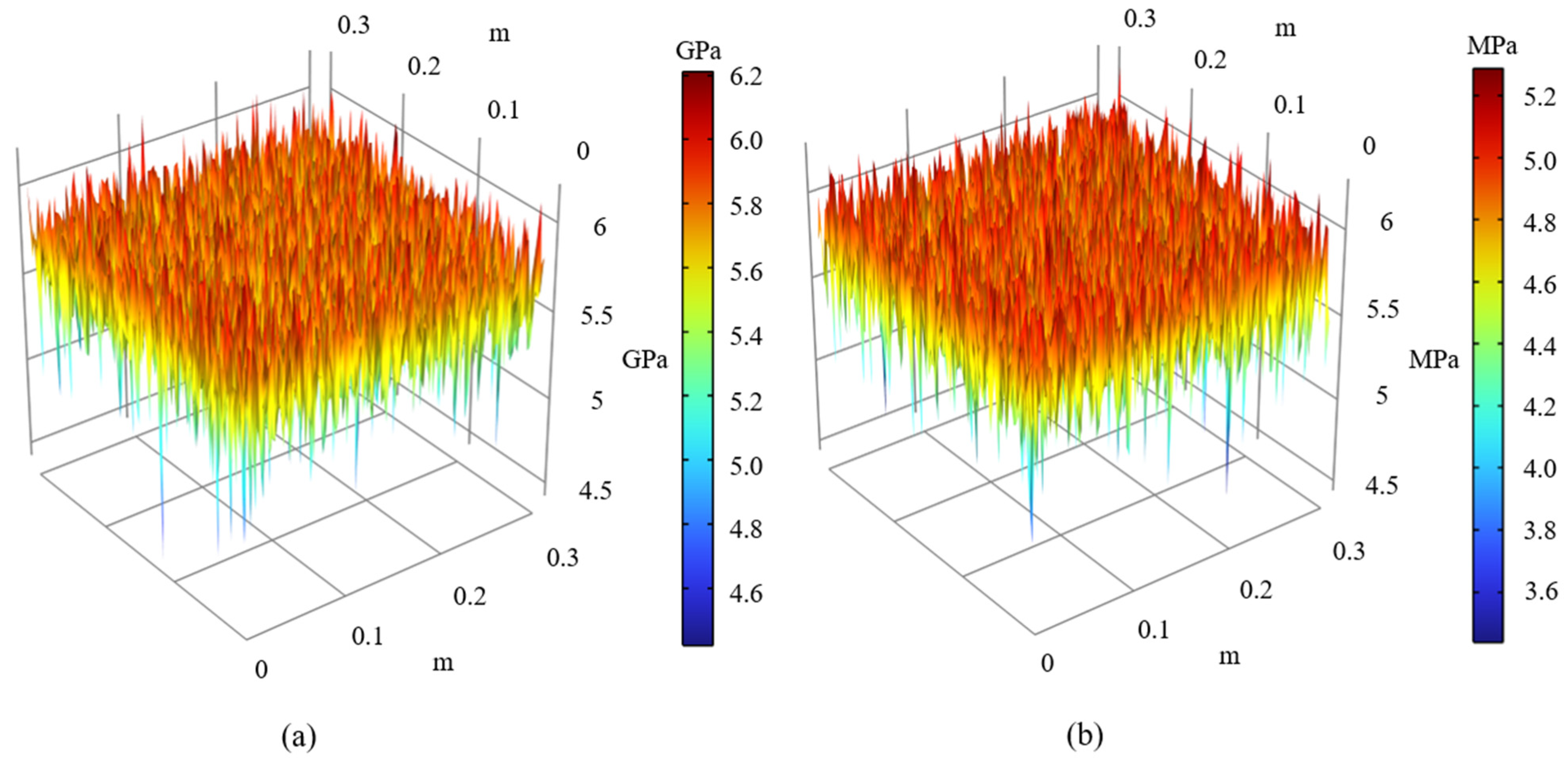
Based on the relevant studies on controlled repeated high-energy shock wave fracturing, a numerical model was established using COMSOL Multiphysics 6.2 finite element [29] software, with a model size of 0.3 m × 0.3 m (Figure 1). The model was discretized using a free triangular mesh in COMSOL Multiphysics. The element size was defined with a minimum of 0.0004 m, a maximum of 0.003 m, and a maximum element growth rate of 1.30. A two-step solution strategy was employed: first, a stationary study was performed to obtain the initial equilibrium state of the stress field. This steady-state solution was then used as the initial condition for a subsequent Time-Dependent study, which utilized an implicit time-stepping solver based on the Backward Differentiation Formula (BDF) to simulate the dynamic evolution of the damage field. For handling nonlinearities, the fully coupled Newton-Raphson method was applied. The numerical simulations were performed on a workstation equipped with an AMD Ryzen 9 9900X 12-Core Processor (4.40 GHz) and 64 GB of RAM. The L1 well in the Linxing block, located at the eastern margin of the Ordos Basin, was taken as an example. The fracture propagation process under the influence of controlled repeated high-energy shock waves was analyzed and compared with the fracture propagation results under hydraulic fracturing. A borehole with a radius of 0.005 m was set at the center of the geometry model, and the computational domain was divided into triangular mesh elements, with a total of 46,010 elements. The geological parameters of L1 well in the Linxing block were collected. Referring to the geological data of L1 well and related literature [30], and taking the Benxi Formation (Nos. 8 and 9 coal) in the Linxing block as the study object, the vertical stress and horizontal principal stress were determined to be 39 MPa and 33 MPa, respectively, with a Poisson’s ratio of 0.35 and an internal friction angle of 30°. The elastic modulus and tensile strength were determined based on a Weibull random distribution, as shown in the Figure 2.
(2)
Boundary Conditions
In the high-energy pulse fracturing process, non-reflective boundary conditions were applied to all four boundaries of the model. Specifically, independent viscous absorbing boundary conditions were set along the normal and tangential directions of the boundaries to absorb incident waves from the interior of the model, as shown in Equations (9)–(12). Stress loads related to boundary node velocity and the velocity of the particles at the boundary were applied as follows [31]:
σ n = 2 ( ρ C p ) v n
σ s = 2 ( ρ C s ) v s
C p = K + 4 G / 3 ρ
C s = G ρ
where σn is the normal stress load, MPa; σs is the shear stress load, MPa; ρ is the medium density, kg/m3; Cp is the wave speed for longitudinal stress waves, m/s; Cs is the wave speed for transverse stress waves, m/s; Vn is the normal velocity of the boundary particles, m/s; Vs is the tangential velocity of the boundary particles, m/s.
(3)
Controlled Repeated High-Energy Shock Wave Pressure–Time History Curve
In the numerical simulation of controlled high-energy shock waves, the pressure amplitude of the shock wave is related to the amount of energetic material [32,33]. Therefore, research on the pressure–time history curve of the shock wave pulse is limited. In this study, a pulse function (Equation (11) defined by the rise time and peak pressure [34] is used to define the pressure–time history curve of the shock wave in the numerical simulation (Figure 1b).
p ( t ) = p max e β t 0 t β t 0 e β t t 0 β t 0
where p is the pulse pressure, MPa; pmax is the peak pulse pressure, MPa; β is a constant; t is the pulse duration, s; t0 is the time from the initial state to the peak pressure, s.
(4)
Model Calculation and Verification
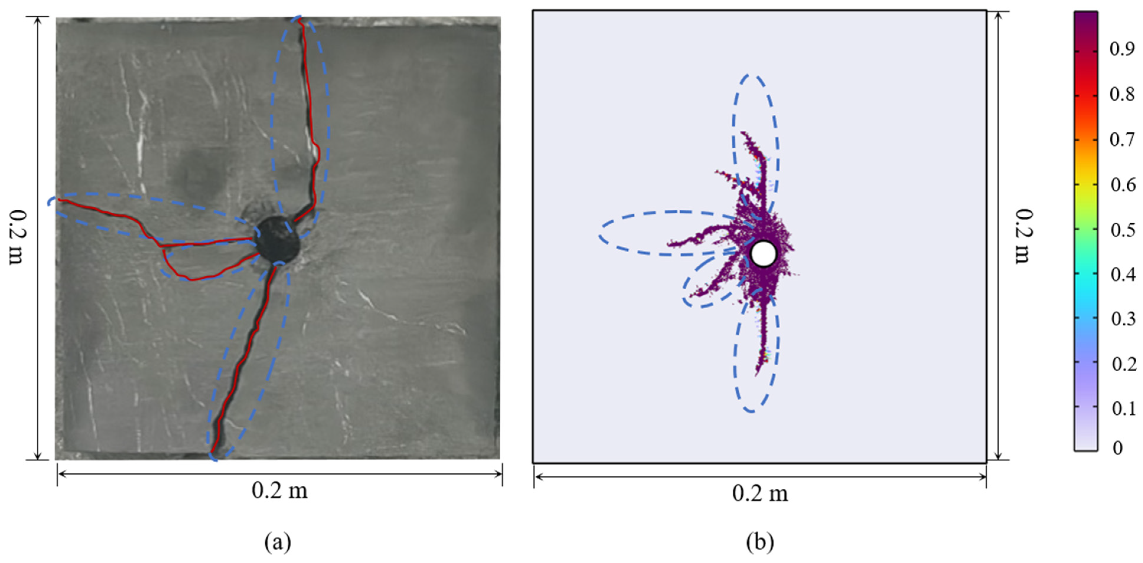
During the numerical model calculation, vertical stress was first applied to the upper part of the model, and horizontal stress was applied to the right boundary, with the remaining boundaries set as roller supports, representing the initial stress state for subsequent fracturing simulations. During the high-energy pulse fracturing numerical simulation, non-reflective boundary conditions were applied to all four boundaries of the model. Using the rock samples collected from the relevant region, the model was validated with the relevant mathematical and geometric models (Figure 3). The fracture propagation trends were consistent, with fractures extending from the upper and lower ends of the borehole and branching occurring on one side.

3. Fracture Propagation Influencing Factors Analysis

3.1. Numerical Simulation Results and Analysis

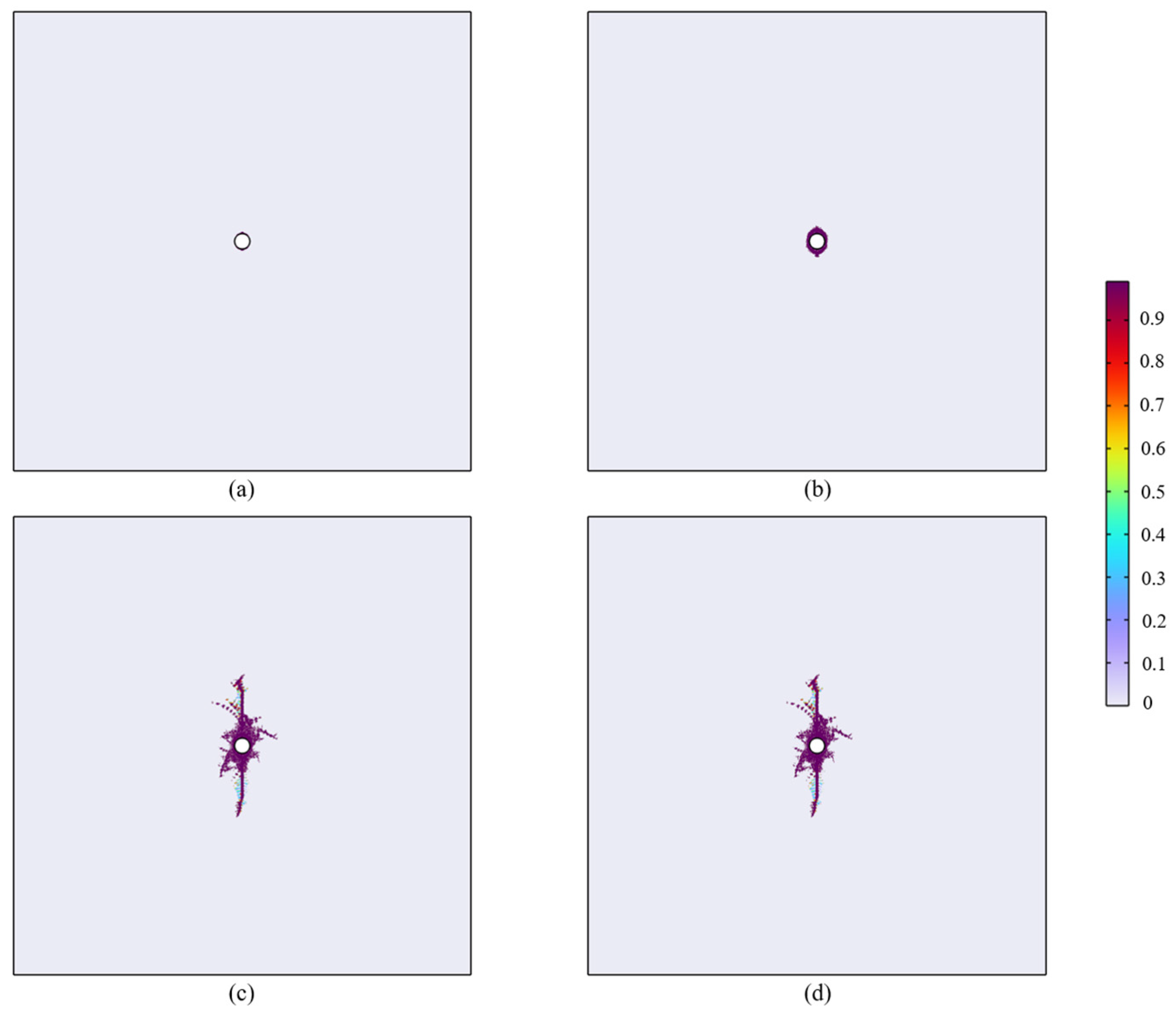
The fracture propagation during the numerical simulation is shown in Figure 4. As shown in the figure, under the effect of controlled high-energy shock wave fracturing, initial clustered fractures begin to form around the borehole at the peak pressure time (20 μs). These fractures expand further with the impact. By 50 μs, the fractures exhibit clear directionality, extending primarily along the maximum principal stress direction. By 100 μs, a significant tensile–shear composite failure mode is observed.
A single-factor analysis was performed on geological structures (tectonic stress, natural fracture development), and operational parameters (pulse pressure, loading and unloading time) to explore their effects on fracture propagation during pulse fracturing. In the single-factor influence simulation, all other parameters were kept constant while only the value of the analyzed factor was changed.

3.2. Effect of Geostress Difference

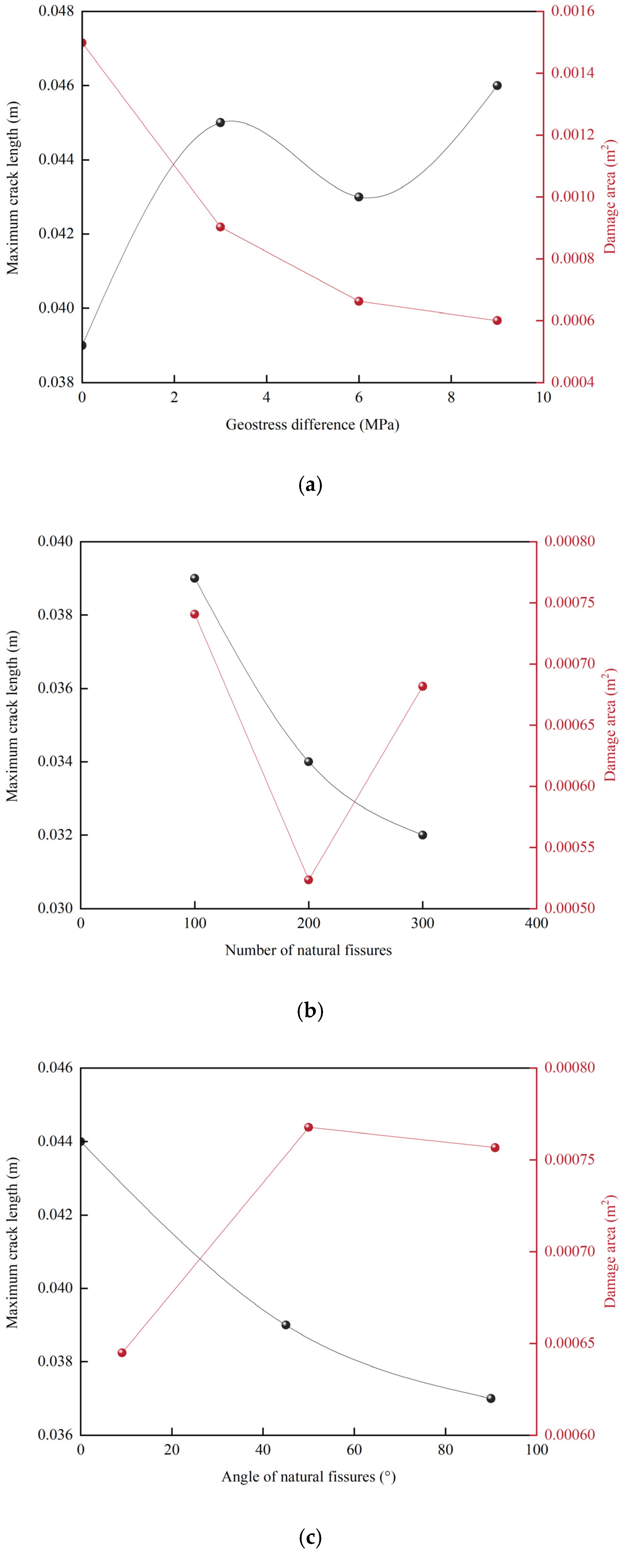
In the Linxing block, the geostress difference between vertical and horizontal principal stresses typically ranges from 5 to 7 MPa [27]. The fracture propagation under different geostress differences (0 MPa, 3 MPa, 6 MPa, 9 MPa) is shown in Figure 5. When the geostress difference is between 0 MPa and 3 MPa, fractures expand in all directions, showing a relatively clear radial pattern. As the geostress difference increases to 6–9 MPa, fracture branching significantly decreases, and the fracture propagation is largely suppressed in the horizontal principal stress direction, favoring extension along the vertical stress (maximum principal stress direction). The damage area and maximum fracture length under different stress states are shown in Figure 4. When the stress difference increases to 9 MPa, the maximum fracture length increases from 0.039 m to 0.046 m, and the fracture damage area increases in a stepwise manner. When the geostress difference is between 6 MPa and 9 MPa, the damage area changes little, decreasing by 40.06% compared to 0 MPa. This suggests that an increase in geostress difference promotes single-direction fracture extension and inhibits the increase in damage area.

3.3. Effect of Natural Fissure Characteristics on Fracture Propagation

Natural fissures have a significant impact on fracture propagation. A simulation was conducted with natural fissures set to 100, 200, and 300 fissures, and the fracture propagation under different natural fissures quantities was analyzed (Figure 6). It was observed that in the presence of natural fissures, fractures propagate along the natural fissure orientation under the impact of the pulse. Natural fissures provide advantageous pathways for controlled shock wave fracturing. When the number of fissures reaches 300, the fracture length along the maximum principal stress direction decreases from 0.039 m to 0.031 m, as fractures consume more energy when communicating through natural fissures, inhibiting further extension.
Additionally, the effect of the natural fissure orientation on fracture propagation was analyzed by setting the number of natural fissures to 200 and varying the angle between the natural fractures and the horizontal principal stress (0°, 45°, 90°). As shown in Figure 7 and Figure 8, when the natural fissure orientation is perpendicular to the maximum principal stress, there are more natural fissures at the upper end of the borehole, which significantly inhibits fracture propagation compared to the lower end of the borehole. As the angle between the natural fissures and the horizontal principal stress increases from 0° to 90°, the fractures tend to branch, and the overall damage area increases compared to the fractures at 0°.

3.4. Effect of Operational Parameters on Fracture Propagation

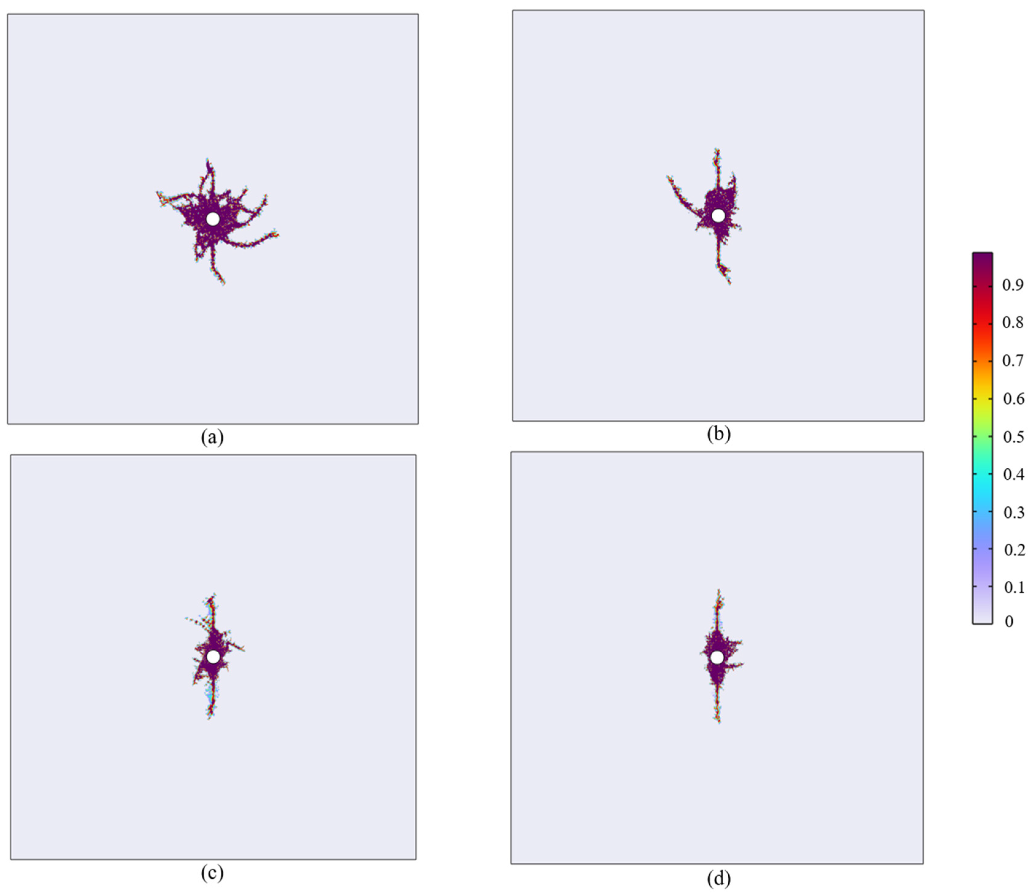
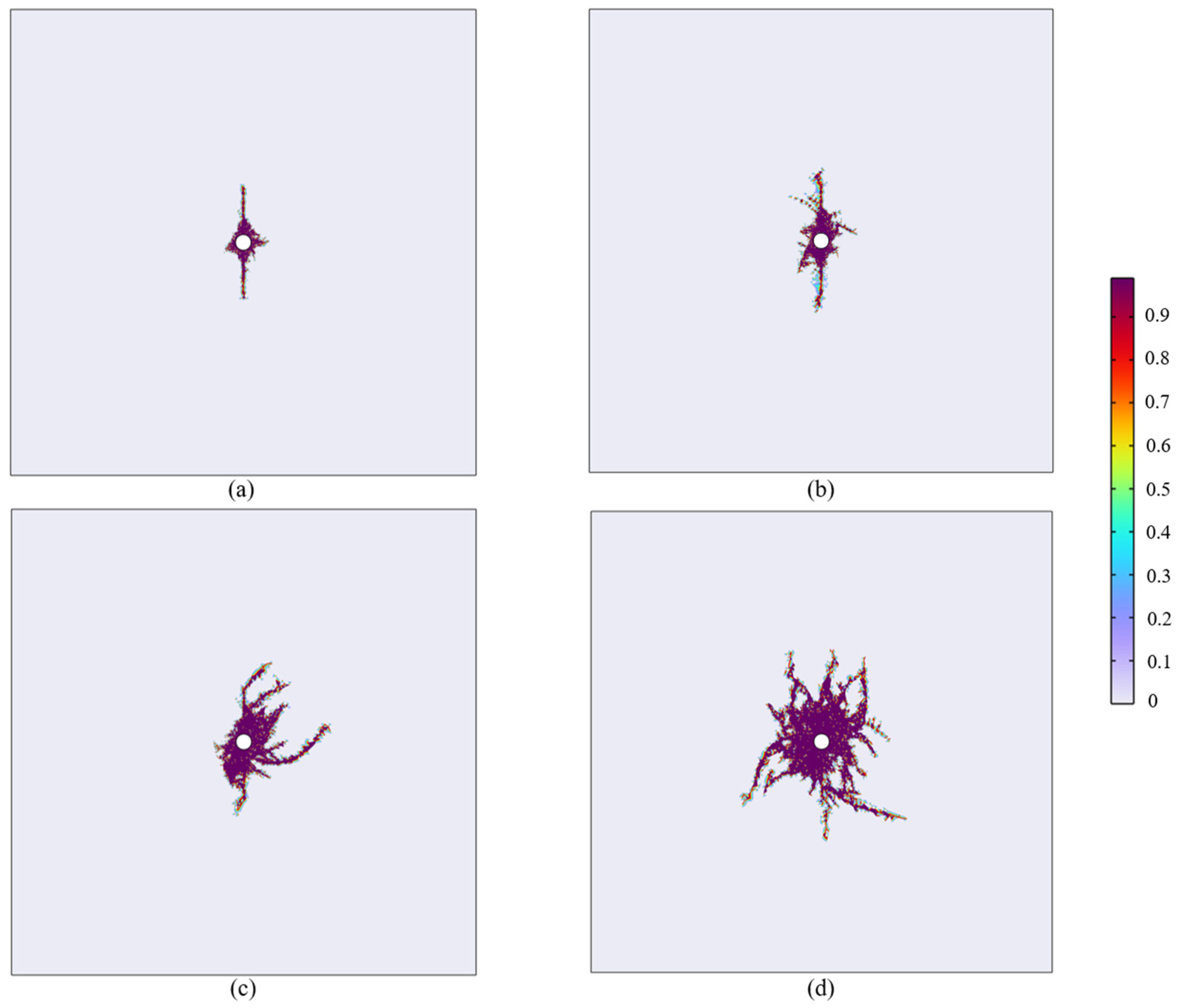
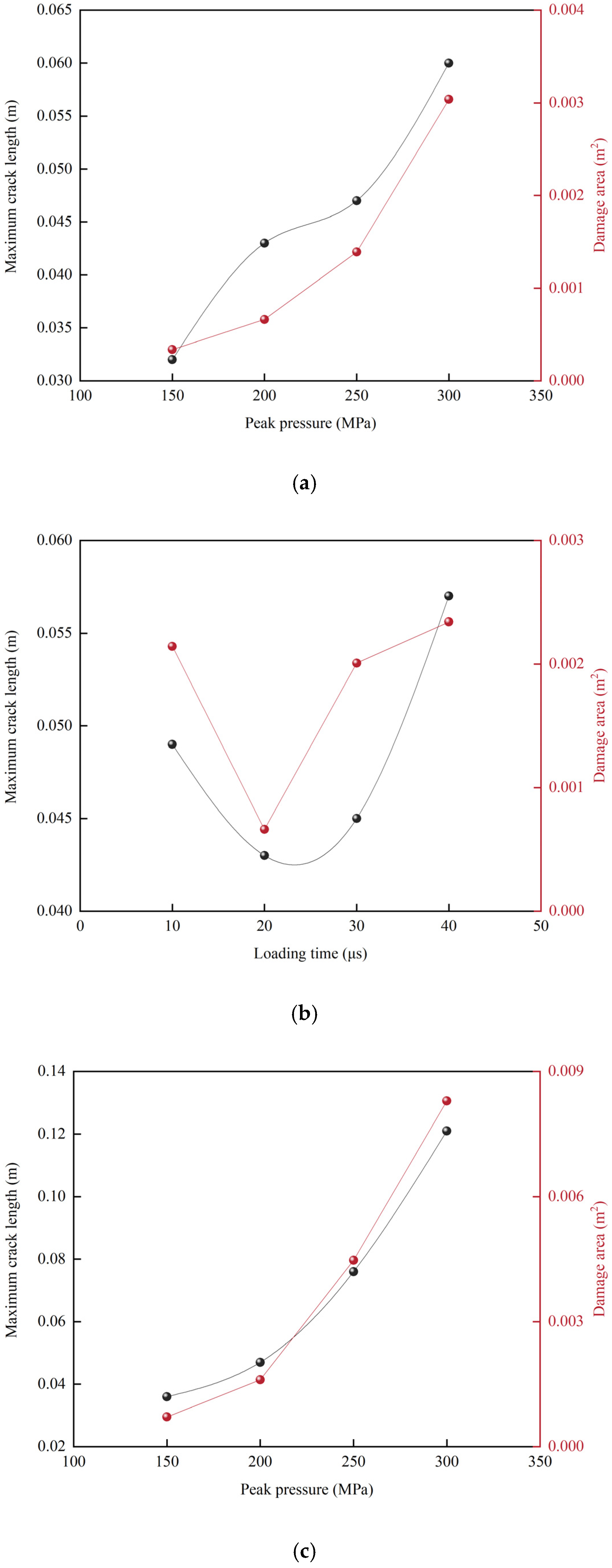
The fracture propagation under different peak pressures (150 MPa, 200 MPa, 250 MPa, 300 MPa) was analyzed (Figure 9). When the peak pressure is between 150 MPa and 200 MPa, the fractures tend to extend along the maximum principal stress direction under the effect of geostress. As the peak pressure increases to 300 MPa, the number of fracture branches increases to 6–7, and the maximum fracture length increases to 0.06 m, significantly larger than the 0.032 m extension at 150 MPa.
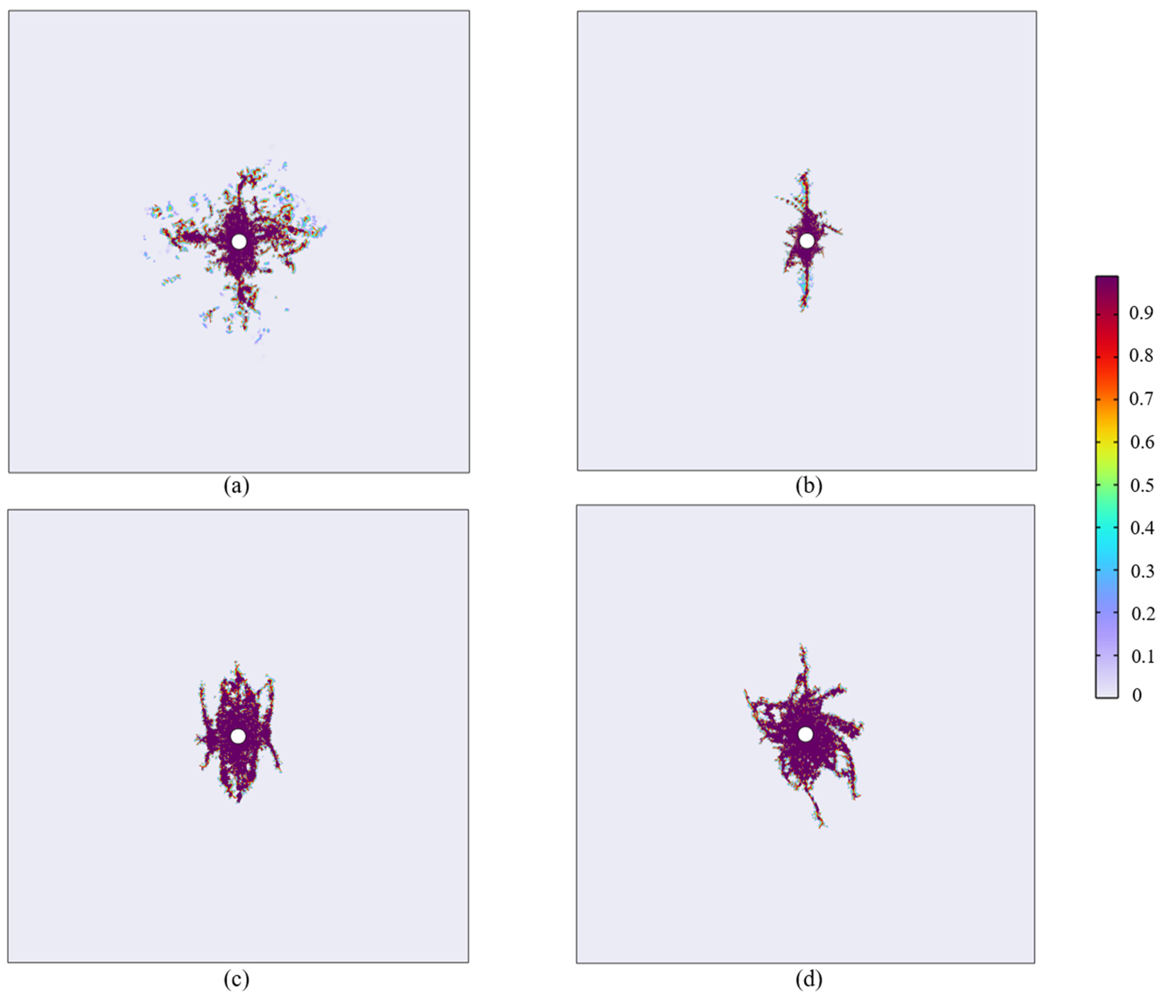
The effect of loading rate on fracture propagation was analyzed by setting the loading time of a single pulse waveform to 10 μs, 20 μs, 30 μs, and 40 μs, while keeping the unloading time constant at 80 μs. As the loading rate increases, the damage around the borehole initially decreases, then increases (Figure 10). The overall trend of fracture extension remains the same (from 0.053 m at 10 μs to 0.057 m at 40 μs). This behavior is due to excessive stress near the borehole when the loading time is too fast, leading to a more severe fracture. When the rise time is increased to 20 μs, passive confining pressure improves the stress state of the rock mass and increases its resistance to fracturing. When the loading rate is further slowed, the dynamic strength decreases, leading to significant increases in fracture propagation and damage.
The effect of repetition of shock pulses was analyzed by setting the number of repetitions to 1 and 2, with peak pressures of 150 MPa, 200 MPa, 250 MPa, and 300 MPa. As the number of shock pulses increases, the maximum fracture length increases significantly under higher peak pressures (≥250 MPa) (Figure 11 and Figure 12). The maximum fracture length increased by 12.5%, 9.3%, 61.7%, and 101.7% for the first shock at the respective pressures. This suggests that multiple shock pulses with higher peak pressures contribute to further extension and an increase in damage area.

4. Analysis and Discussion

4.1. Sensitivity Analysis of Factors Affecting Fracture Propagation

The analysis above demonstrates that geological and engineering parameters significantly influence fracture propagation. To quantify the degree of influence of specific parameters, the ratio of the damage area to the total area under single-factor influence is used as an indicator. The formula is as follows:
H = Δ L Δ P / P max
where ΔL is the change in the maximum fracture half-length, m; ΔP is the change in the parameter influencing fracture propagation; Pmax is the maximum value of the parameter influencing fracture propagation.
The sensitivity coefficients of various influencing factors are presented in Table 1, with the results indicating the following order of influence: repeated shocks > peak stress > geostress difference > loading time > angle of natural fissures > Number of natural fissures. Among these, the number of natural fractures exhibits a relatively minor impact on fracture propagation, while the number of repeated shocks and the peak stress exert more substantial control over both fracture extension and the damage area. This finding highlights the distinct advantage of engineering parameters (such as repeated shocks and peak stress) over geological parameters in promoting fracture propagation, underscoring the importance of focusing on stress conditions and repeated shock strategies in the design of controlled high-energy shock wave fracturing. From a mechanistic perspective, repeated shocks significantly enhance the rupture degree of the coal matrix through a fatigue damage accumulation mechanism, while high peak stress directly determines the initiation energy required for initial fractures. The synergistic effect of these two factors provides the essential conditions for the formation of a complex fracture network. Based on these findings, this study recommends employing a combination of engineering parameters—specifically, a peak pressure of ≥250 MPa, repeated shocks of ≥2 cycles, and a loading time of approximately 30–40 μs—when implementing shock wave fracturing, provided that geological conditions are well understood.
The determination of this parameter range is grounded in the distinct damage threshold effects observed in numerical simulations: a peak pressure of ≥250 MPa initiates significant damage in the coal matrix, repeated shocks of ≥2 cycles ensure effective fracture propagation, and a loading time of 30–40 μs balances sufficient energy input with the prevention of premature energy dissipation. Through this optimized parameter combination, the most favorable fracture propagation outcomes can be achieved, offering clear technical guidance for field operations.

4.2. Comparison with Hydraulic Fracturing

A comparative numerical simulation study conducted under identical coal seam conditions further reveals the distinct advantages of controlled repeated high-energy shock wave fracturing over conventional hydraulic fracturing. In terms of the operating mechanism, hydraulic fracturing typically requires on the order of minutes to complete fracture initiation and propagation, whereas controlled high-energy shock waves achieve energy release within microseconds to milliseconds. This instantaneous high-energy loading characteristic provides an order-of-magnitude advantage in operational efficiency. Regarding fracture morphology, shock wave action readily generates multiple radial main fractures and abundant short fracture branches around the borehole, while hydraulic fracturing under an in situ stress of 6 MPa tends to form a relatively simple planar fracture system (Figure 13). From the perspective of pressure mechanisms, hydraulic fracturing relies on the slow injection of fracturing fluid to gradually increase reservoir pressure, with its peak pressure typically rising by tens of megapascals above the initial pressure [9], yet remaining significantly lower than the peak pressure of controlled repeated high-energy shock wave fracturing (≥250 MPa). This high-pressure characteristic enables shock wave fracturing to overcome higher geo-stress barriers and achieve effective fracturing under more complex geological conditions. Compared to the operational features of hydraulic fracturing, the shock wave fracturing technology employed in this study not only significantly enhances fracture complexity but also avoids common issues associated with hydraulic fracturing, such as water consumption and environmental contamination, thereby offering a new technical alternative for coalbed methane development in arid areas and ecologically sensitive regions.

5. Conclusions

Based on numerical simulation of controlled repeated high-energy shock wave fracturing combined with systematic comparison with traditional hydraulic fracturing, this study reveals the influence of geological and engineering factors, clarifies the significant technical advantages of this method in coalbed methane development, and proposes an optimized engineering implementation plan. The main conclusions are as follows:
Geostress difference (≥6 MPa) significantly promotes fracture extension along the direction of the maximum principal stress and fracture formation. The angle between the orientation of natural fractures and the direction of the principal stress affects the fracture propagation path, and an angle of 90° between the natural fracture orientation and the horizontal principal stress inhibits fracture extension.
On this basis, sensitivity analysis further reveals the critical role of engineering parameters. The number of shock cycles and the peak pressure have the most significant impact on fracture propagation, while a longer loading time also contributes to fracture generation and improves propagation stability. Accordingly, a parameter combination of peak pressure ≥ 250 MPa, repeated shocks ≥ 2 times, and loading time of 30–40 μs is proposed, providing a basis for achieving efficient and controllable fracture extension.
The radial fracture system generated by high-energy shock waves demonstrates significant advantages in connecting rock layers and natural fractures. Compared to hydraulic fracturing, this method not only achieves rapid propagation on the order of milliseconds to microseconds but also operates without water. While effectively enhancing coal seam permeability and porosity, it avoids water consumption and reservoir contamination, offering a more sustainable technological pathway for coalbed methane development in arid regions and environmentally sensitive areas.

Author Contributions

Conceptualization, S.W. and S.L.; Methodology, S.W.; Software, S.W.; Validation, S.W., W.L. and Y.L. (Yonglong Li); Formal Analysis, S.W.; Investigation, L.Z., Y.L. (Yan Liang), X.L. and S.P.; Resources, S.W. and S.L.; Data Curation, S.W. and W.L.; Writing—Original Draft Preparation, S.W., W.L., Y.L. (Yonglong Li) and L.Z.; Writing—Review and Editing, Y.L. (Yan Liang), X.L., S.P., Y.L. (Yu Liang) and S.L.; Visualization, W.L. and Y.L. (Yonglong Li); Supervision, S.W. and S.L.; Project Administration, S.L.; Funding Acquisition, S.W. All authors have read and agreed to the published version of the manuscript.

Funding

This research was funded by China National Petroleum Corporation Scientific Research and Technology Development Project, grant number 2024DJ2303 and the National Natural Science Foundation of China, grant number 42030810.

Data Availability Statement

The original contributions presented in the study are included in the article, further inquiries can be directed to the corresponding author.

Conflicts of Interest

Authors Sukai Wang, Wei Liu, Yonglong Li, Lipeng Zhang, Yan Liang, Xionghui Liu and Songling Pu were employed by the company, Engineering Technology Research Institute of CNPC Xibu Drilling Engineering Co., Ltd. The remaining authors declare that the research was conducted in the absence of any commercial or financial relationships that could be construed as a potential conflict of interest.

References

  1. Xu, F.Y.; Hou, W.; Xiong, X.Y.; Xu, B.R.; Wu, P.; Wang, H.Y.; Feng, K.; Yun, J.; Li, S.G.; Zhang, L.; et al. The status and development strategy of coalbed methane industry in China. Pet. Explor. Dev. 2023, 50, 765–783. [Google Scholar] [CrossRef]
  2. Huo, C.; Guo, H.X.; Wang, L.; Xie, Z.Q.; Pan, H.Y.; Xu, Q.; Zhang, Z.G.; Wang, D.F.; Wang, D.D. Research Progress of Deep Coalbed Methane Exploration and development in China under the dual carbon background. Sci. Technol. Eng. 2025, 25, 5705–5720. [Google Scholar] [CrossRef]
  3. Ju, W.; Tao, S.; Yang, Z.B.; Cheng, J.X.; Shang, H.Y.; Ning, W.K.; Wu, C.L. Current status and development trends of deep coalbed methane research in China. Pet. Geol. Exp. 2025, 47, 9–16. [Google Scholar] [CrossRef]
  4. An, Y.S.; Sun, Z.W.; Wang, J.; Zhang, X.Y.; Sun, Y.F. Numerical simulation of deep coalbed methane development based on embedded discrete fracture model: A triple medium flow approach. Energy Sci. Eng. 2025, 13, 3045–3062. [Google Scholar] [CrossRef]
  5. Liu, J.Z.; Su, Y.C.; Sun, L.C.; Li, C.; Wang, L.; Meng, Y.J.; Li, Y. Research on fracturing optimization of coalbed methane wells aiming at economic benefit—A case study of Liulin block. Energies 2024, 17, 1829. [Google Scholar] [CrossRef]
  6. Xie, H.G.; Sang, S.S.; Li, X.J.; Yan, Z.H.; Zhou, X.Z.; Liu, S.Q.; Han, S.J.; Cai, J.J. Competitive adsorption-penetration characteristics of multi-component gases in micro-nano pore of coal. Chem. Eng. J. 2025, 506, 159965. [Google Scholar] [CrossRef]
  7. Xie, H.G.; Sang, S.X.; Li, X.J.; Yan, Z.H.; Liu, S.Q.; Zhou, X.Z.; Han, S.J. Evolution of pore-fracture and permeability prediction in soft coal rock under variable-pressure water saturation. Phys. Fluids 2025, 37, 76646. [Google Scholar] [CrossRef]
  8. Qiao, G.D.; Liu, Z.G.; Gao, K.; Zhang, Y.M.; Zhao, Y.Z.; Li, Y.Y.; Fu, S.G.; Zhang, J.Y.; Wang, Z.; Yang, S.; et al. Evolutionary patterns of cracking and damage due to anti-reflection of controllable shock waves at the roof of loose and low-permeability coal seams. J. China Coal Soc. 2025. [Google Scholar] [CrossRef]
  9. Zhao, X.L.; Huang, B.X.; Li, H.Z.; Chen, S.L. Field investigation of multi-stage pulse hydraulic fracturing for improving permeability of coal seam in directional long borehole in underground coal mines. Environ. Earth Sci. 2023, 82, 519. [Google Scholar] [CrossRef]
  10. Li, N.Y.; Wang, C.; Zhang, S.W.; Yu, J.J. Recent advances in waterless fracturing technology for the petroleum industry: An overview. J. Nat. Gas Sci. Eng. 2021, 92, 103999. [Google Scholar] [CrossRef]
  11. Xie, H.C.; Ni, G.H.; Xie, J.N.; Cheng, W.M.; Xun, M.; Wang, H.; Wang, G. The effect of SDS synergistic composite acidification on the chemical structure and wetting characteristics of coal. Powder Technol. 2020, 367, 253–265. [Google Scholar] [CrossRef]
  12. Zhou, X.H.; Li, X.L.; Bai, G.; Chai, L.; Wang, Y.M.; Xiao, M.F.; Xia, S.Y. Research method of pressure relief and permeability enhancement in low permeability coal seam: A review. AIP Adv. 2022, 12, 010702. [Google Scholar] [CrossRef]
  13. Fan, C.J.; Sun, H.; Li, S.; Yang, L.; Xiao, B.; Yang, Z.H.; Luo, M.K.; Jiang, X.F.; Zhou, L.J. Research advances in enhanced coal seam gas extraction by controllable shock wave fracturing. Int. J. Coal Sci. Technol. 2024, 11, 39. [Google Scholar] [CrossRef]
  14. Qiao, G.D.; Liu, Z.G.; Zhang, Y.M.; Yi, C.P.; Gao, K.; Fu, S.G.; Zhao, Y.Z. Theoretical analysis and engineering application of controllable shock wave technology for enhancing coalbed methane in soft and low-permeability coal seams. Int. J. Coal Sci. Technol. 2024, 11, 25. [Google Scholar] [CrossRef]
  15. An, S.G.; Chen, D.B.; Zhang, Y.M.; Kong, D.L.; Li, Y.; Zhang, D.; Wang, Y. Application of controllable electric pulse wave permeability-enhancing technology in the low-permeability coal seams. Coal Geol. Explor. 2020, 48, 138–145. [Google Scholar] [CrossRef]
  16. Wang, Z. Application of controllable shock wave plugging removal and permeability improvement technology in CBM gas field of Southern Yanchuan. Pet. Reserv. Eval. Dev. 2020, 10, 87–92. [Google Scholar] [CrossRef]
  17. Wang, S.B.; Zhang, S.; Ma, L.; Zhao, Y.Z.; Gao, L.; Cao, Y.X.; Xie, P.J. Physical simulation experiment on the rock breaking efficiency of pulse type controllable shock wave. ACS Omega 2024, 9, 51554–51569. [Google Scholar] [CrossRef]
  18. Han, Z.J.; Liu, M.J.; Zhang, J.C. The rock breaking mechanism and application effect of pulse type controllable shock wave. Geomech. Geophys. Geo-Energy Geo-Resour. 2025, 11, 18. [Google Scholar] [CrossRef]
  19. Chen, H.J.; Chen, Z.; Hu, B.; Hu, Q.Y.; Zhao, Y.Z. Optimization of parameters for controllable shock waves pre-splitting in hard rocks in tectonic zones. J. Xi’an Univ. Sci. Technol. 2024, 44, 857–865. [Google Scholar] [CrossRef]
  20. Qin, Y.; Li, H.L.; Zhang, Y.M.; Zhao, Y.Z.; Zhao, J.C.; Qiu, A.C. Numerical analysis on CSW fracturing behavior of coal seam under constraint of geological and engineering conditions. Coal Geol. Explor. 2021, 49, 108–118+129. [Google Scholar] [CrossRef]
  21. Sun, H.; Fan, C.J.; Yang, L.; Luo, M.K.; Wang, L.; Zhou, L.J. Modelling of enhanced gas extraction in low permeability coal seam by controllable shock wave fracturing. Sci. Rep. 2024, 14, 24155. [Google Scholar] [CrossRef] [PubMed]
  22. Li, H.L. Behavior and Mechanism of Fracturing and Enhanced-Permeability of Coals with Electric Pulse Stress Waves. Ph.D. thesis, China University of Mining and Technology, Xuzhou, China, 2015. [Google Scholar]
  23. Wang, W.W.; Lv, C.G.; Mu, C. Fractal Characterization of Surrounding Rock and Coal Matrix Stress Response Enhancing Gas Drainage Efficiency. ACS Omega 2025, 10, 10459–10467. [Google Scholar] [CrossRef] [PubMed]
  24. Liu, S.Q.; Fang, H.H.; Sang, S.X.; Hu, Q.J.; Duan, W.Y.; Jia, H.M.; Mao, C.H. Numerical simulation of gas production for multilayer drainage coalbed methane vertical wells in southern Qinshui Basin. Coal Geol. Explor. 2022, 50, 20–31. [Google Scholar] [CrossRef]
  25. Wu, L.; Hou, Z.M.; Xie, Y.C.; Luo, Z.F.; Xiong, Y.; Cheng, L.; Wu, X.N.; Chen, Q.J.; Huang, L.C. Fracture initiation and propagation of supercritical carbon dioxide fracturing in calcite-rich shale: A coupled thermal-hydraulic-mechanical-chemical simulation. Int. J. Rock Mech. Min. Sci. 2023, 167, 105389. [Google Scholar] [CrossRef]
  26. Lin, H.F.; Li, B.T.; Li, S.G.; Song, Z.X.; Wang, F.; Luo, R.W.; Wei, Z.Y.; Qin, L. A thermal-hydraulic-mechanical-damage coupling model of layer coal fracturing by liquid nitrogen. Chin. J. Rock Mech. Eng. 2024, 43, 1110–1123. [Google Scholar] [CrossRef]
  27. Zhu, W.C.; Wei, C.H.; Tian, J.; Yang, T.H.; Tang, C.A. Coupled thermal-hydraulic-mechanical model during rock damage and its preliminary application. Rock Soil Mech. 2009, 30, 3851–3857. [Google Scholar] [CrossRef]
  28. Zhang, H.B.; Liu, J.S.; Elsworth, D. How sorption-induced matrix deformation affects gas flow in coal seams: A new FE model. Int. J. Rock Mech. Min. Sci. 2008, 45, 1226–1236. [Google Scholar] [CrossRef]
  29. Li, S.; Fan, C.J.; Han, S.; Luo, M.K.; Yang, Z.H.; Bi, H.J. A fully coupled thermal-hydraulic-mechanical model with two-phase flow for coalbed methane extraction. J. Nat. Gas Sci. Eng. 2016, 33, 324–336. [Google Scholar] [CrossRef]
  30. Yang, F.; Li, B.; Wang, K.J.; Wen, H.; Yang, R.Y.; Huang, Z.W. Extreme massive hydraulic fracturing in deep coalbed methane horizontal wells: A case study of the Linxing Block, eastern Ordos Basin, NW China. Pet. Explor. Dev. 2024, 51, 389–398. [Google Scholar] [CrossRef]
  31. Yan, C.Z.; Sun, G.H.; Zheng, H.; Ge, X.R. Simulation of explosive gas-driven rock fracture by FEM/DEM. Rock Soil Mech. 2015, 36, 2419–2425. [Google Scholar] [CrossRef]
  32. Wang, E.B.; Zhu, H.Y.; Yi, X.Y.; Li, Q.; Zhao, P.; Marembo, M.; Tan, H.J.; Zhang, Z.P. Numerical simulation of fracture propagation in high-energy gas fracturing of shale reservoir. Geoenergy Sci. Eng. 2025, 252, 213915. [Google Scholar] [CrossRef]
  33. Ding, J.H.; Liu, M.J.; Zhang, Y.; Sun, X.; Niu, Q.H.; Wang, W.; Wang, W.; Zheng, Y.X.; Yin, C. Experimental and numerical simulation research on controllable shock wave-induced shale fracturing under repeated action. ACS Omega 2024, 9, 13252–13261. [Google Scholar] [CrossRef] [PubMed]
  34. Lin, M.H. Mechanism on Targeted Blasting Fracturing and Enhanced Permeability in Deep Coal Rock Mass and Its Engineering Application. Ph.D. thesis, China University of Mining and Technology, Xuzhou, China, 2024. [Google Scholar]
Figure 1. Geometry model and pressure–time history curve. (a) Geometric model; (b) pressure–time history curve.
Applsci 15 12279 g001
Figure 2. Distribution of coal seam elastic modulus and tensile strength. (a) Elastic modulus; (b) Tensile strength.
Applsci 15 12279 g002
Figure 3. Comparison of experimental and numerical simulation results (the red line and the purple line represent the fracture propagation in the experiment and the numerical simulation, respectively.). (a) Experimental result; (b) Numerical simulation result.
Applsci 15 12279 g003
Figure 4. Fracture propagation mode. (a) 10 μs; (b) 20 μs; (c) 50 μs; (d) 100 μs.
Applsci 15 12279 g004
Figure 5. Effect of geostress difference on fracture propagation. (a) 0 MPa; (b) 3 MPa; (c) 6 MPa; (d) 9 MPa.
Applsci 15 12279 g005
Figure 6. Effect of the number of natural fissures on fracture propagation (the short dash lines represent natural fractures.). (a) 100 natural fissures; (b) 200 natural fissures; (c) 300 natural fissures.
Applsci 15 12279 g006
Figure 7. Effect of the angle of the natural fissures on fracture propagation (the short dash lines in the figure represent natural fractures.). (a) 0°; (b) 45°; (c) 90°.
Applsci 15 12279 g007
Figure 8. The influence of geological structure on fracture propagation. (a) Geostress difference; (b) Number of natural fissures; (c) Angle of natural fissures.
Applsci 15 12279 g008
Figure 9. Effect of peak pressure on fracture propagation. (a) 150 MPa; (b) 200 MPa; (c) 250 MPa; (d) 300 MPa.
Applsci 15 12279 g009
Figure 10. Effect of loading time on fracture propagation. (a) 10 μs; (b) 20 μs; (c) 30 μs; (d) 40 μs.
Applsci 15 12279 g010
Figure 11. Effect of repeated shocks on fracture propagation. (a) 150 MPa; (b) 200 MPa; (c) 250 MPa; (d) 300 MPa.
Applsci 15 12279 g011
Figure 12. Fracture propagation with peak pressure, loading time and repeated shocks. (a) Peak pressure; (b) Loading time; (c) Peak pressure.
Applsci 15 12279 g012
Figure 13. The comparison of controlled shock wave fracturing and hydraulic fracturing. (a) Controlled shock wave fracturing; (b) Hydraulic fracturing.
Applsci 15 12279 g013
Table 1. Sensitivity coefficients of factors affecting fracture propagation.
ParameterSensitivity CoefficientRank
Geostress difference0.05373
Number of natural fissures0.00016
Angle of natural fissures 0.00205
Peak stress0.35262
Loading time 0.03594
Repeated shocks1.00001
Disclaimer/Publisher’s Note: The statements, opinions and data contained in all publications are solely those of the individual author(s) and contributor(s) and not of MDPI and/or the editor(s). MDPI and/or the editor(s) disclaim responsibility for any injury to people or property resulting from any ideas, methods, instructions or products referred to in the content.