1. Introduction
Composites have been widely utilized in engineering structures since the 1960s, and in some aspects they provide higher mechanical and chemical performances than their counterpart metals, such as specific strength, corrosion resistance and fatigue life [
1,
2,
3,
4,
5]. Therefore, the design and analysis methods of composite structures have gained more and more attention, especially for large-scale engineering structures such as aircrafts [
6,
7,
8], marine structures [
9,
10], space vehicles [
11,
12] and automotive constructions [
13,
14]. Both Boeing and Airbus companies have significantly increased the proportion of composite materials in their new generation of airliners, in order to reduce structural weight and improve flight performance. Hence, an increased proportion of composite materials in structural design has become an important index to gauge the advancement of new types of aircraft.
Thin-walled FRP composite structures are predominantly designed based on the buckling failure modes [
15]; however, these structures have a large post-buckling region [
16]. Therefore, major structural efficiency improvements can be obtained by utilizing these margins. However, in contrast to the metallic structures, where post-buckling design theories are well-matured, the failure modes in FRP-laminated composite structures cannot be accurately predicted due to the anisotropic nature of the composite materials [
17,
18]. Similarly, excessive out-of-plane deformations are not permitted in some aeronautical structures, such as wing and tail structures. Consequently, structural stability analysis has recently become a focused area of research [
19,
20].
Post-buckling analysis of composite structures can be carried out by using different approaches depending on the complexity of the problem [
21,
22,
23,
24]. For instance, approximate solutions can be obtained by the analytical formulation for fast computations and fewer degrees of freedom than the finite element models, which gives accurate results for complex problems [
25,
26]. Additionally, in order to deal with three-dimensional effects due to the out-of-plane and lateral deformations of structures in the post-buckling phase, a detailed analysis of such structures is required, which is computationally expensive. Therefore, efficient numerical simulation procedures are required, which enhance the computational efficiency of modern optimization frameworks [
27,
28,
29].
In this article, a progressive failure analysis [
30] was conducted using numerical simulations in ANSYS 2021 R2 finite element software to predict the nonlinear response and failure characteristics of a laminated FRP composite plate structure under compressive loading. The FE simulation for failure analysis uses shell elements based on Classical Laminate Plate Theory (CLPT) to calculate the in-plane stresses [
31]. The progressive failure analysis uses 3D failure criterion LaRC04 [
32] for damage detection and the stiffness degradation model [
33] for damage propagation in the laminated structure. The failure analysis results of the investigated composite laminated plate structure are compared with earlier published computational and experimental data to evaluate the accuracy and reliability of the proposed analysis methodology.
The research study is organized as follows:
Section 2 describes the current and future design scenarios for structural stability analysis and the building block approach used for the design of composite structures.
Section 3 details the progressive damage model used for the present study; furthermore,
Section 4 describes the progressive failure analysis of the FRP-laminated composite plate structure using ANSYS FE simulations.
Section 5 discusses the ANSYS FE analysis results and comparison with the earlier published data. Finally,
Section 6 concludes the post-buckling analysis results of the investigated laminated FRP plate structure.
This study proposes a numerical simulation procedure using a progressive damage model to predict the post-buckling response, i.e., failure modes and collapse loads of composite laminated structures under compressive loading. The simulation procedure uses a progressive damage model implemented in commercial FE software ANSYS to detect the damage initiation and subsequent damage propagation leading to the collapse of the laminated composite plate structure.
2. Stability Analysis of Laminated FRP Composite Structures
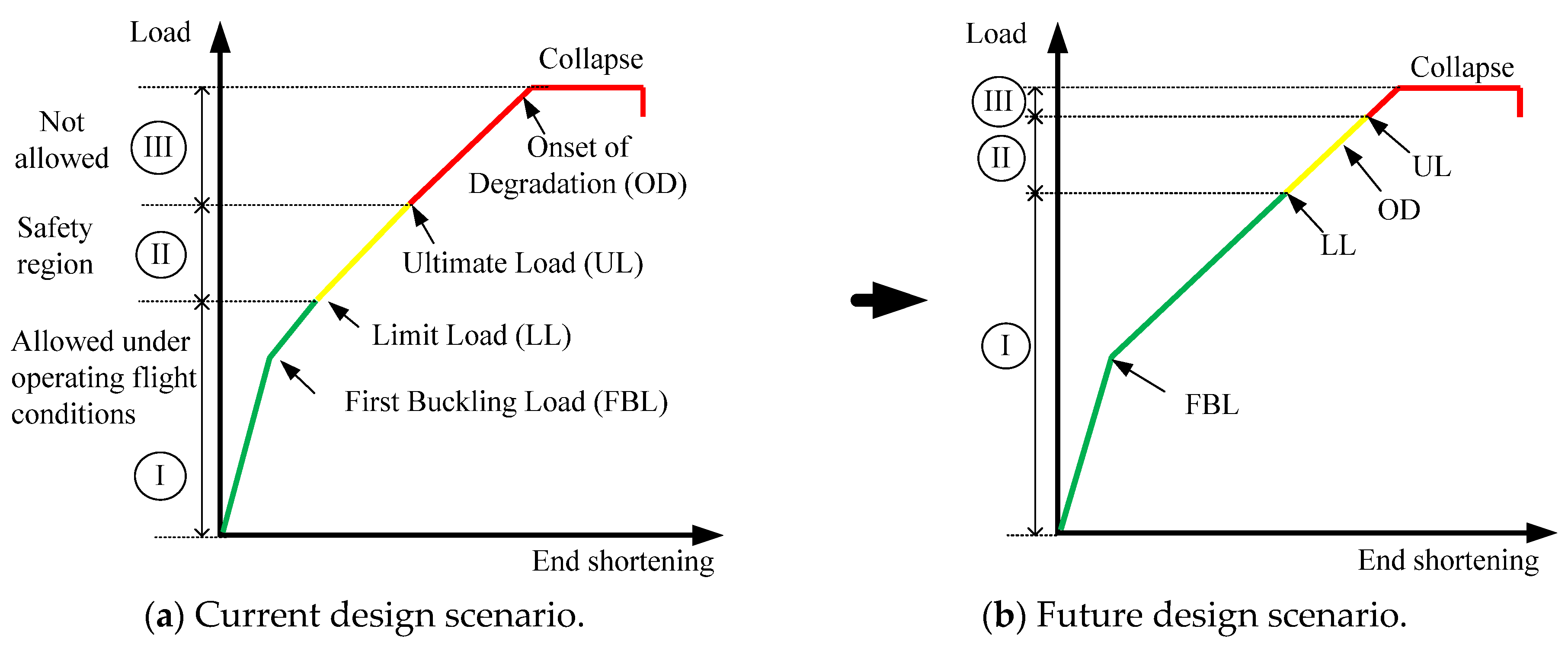
Figure 1 shows the currently used and the suggested future scenarios for the post-buckling design of laminated FRP composite structures. Post-buckling and collapse analysis of large composite structures offers a major weight-saving potential, since it allows for shifting the ultimate load close to the collapse load. This shift will increase the load-bearing capacity of the composite structures, which will result in considerable weight reduction in large composite constructions, such as aircraft fuselages [
34].
Figure 1a describes a current design practice for buckling analysis of laminated composite fuselage structures in terms of a typical load and end shortening curve under compressive loading. The curve is divided into three regions: Region I. is bound by Limit Load (LL), where operating flight loads are permitted; Region II. corresponds to the Ultimate Load (UL), which is taken as 150% of the Limit Load (LL) in aircraft design [
35,
36], serving as the safety margin; Region III. shows the onset of degradation leading to the structural collapse, and structures are not permitted to be operated in this region. In contrast,
Figure 1b shows the suggested future design scenario [
34,
35], in which the ultimate load is shifted near the collapse load, and onset of degradation is allowed in the safety region but not allowed to occur below the LL. This new design scenario is aimed at reducing the structural weight of composite constructions and using the considerable strength reserves available with the FRP composite materials in the post-buckling region. Due to the anisotropy of the composite materials and geometric nonlinearities, more accurate, fast and reliable collapse simulations are required to design the laminated FRP composite structures deep into the post-buckling region.
Recent research works are focused on establishing advanced design scenarios in which local skin buckling is permitted clearly below the LL. The load factor depends on the specific loading conditions; for example, in the case of axial compression, it is 0.7 LL [
34,
35,
36]. This loading factor is different for pure shear and combined loading conditions. However, it has to be ensured that the global buckling, which is regarded as the total loss of stability and load-carrying capacity of the structure, occurs clearly above the ultimate load. Such a scenario contributes to exploiting the load-carrying capacity of composite materials in the post-buckling region and finally leads to a significant structural weight reduction.
Currently applied design approaches do not take this potential into account, since damage with the corresponding degradation in the laminate may occur in the post-buckling region, which finally leads to the collapse of the structure. Efforts are made to simulate this phenomenon accurately enough in the design processes. Including these effects in the nonlinear post-buckling simulations of the composite structures requires numerical models that consider geometric and material nonlinearities. These high-fidelity FE-based numerical simulations, validated by experiments, are essential in the design process to determine the loading potential of composite constructions in the post-buckling region, without the onset of degradation.
Building Block Approach for Composite Structural Design
Due to the highly nonlinear nature of the post-buckling analysis, currently, the load-carrying capacity of the composite structures is not fully utilized. To reduce the computational cost of these nonlinear FE simulations, the building block approach is commonly used for the design and certification of composite constructions. In order to illustrate this approach, a characteristic structural levels pyramid for an aircraft fuselage is shown in
Figure 2 [
37].
The horizontal arrows in
Figure 2 show the validation of different levels (component level, subcomponent level, structural element level and coupon level) of numerical simulations with experimentations. Different levels are connected by the vertical arrows, which can be achieved by utilizing the more advanced multi-scalar options available in commercial FEA codes, such as the sub-modeling technique. By the use of these multi-scalar approaches, we can identify the hot spots and the critical areas of possible failures [
38].
The recently used ratio of analysis and experimentation is shown by the symmetric dashed blue lines, and the outer solid red lines show the future design scenario, where the ratio of analysis is increased compared to the costly validation experiments. The analysis share can be increased by more reliable and accurate multi-scalar analysis procedures, as shown by the distorted pyramid. This will not only reduce the more expensive and time-consuming experiments required for structural qualification but also mitigate the risk of failures in the development process by utilizing high-fidelity simulations in the early stages of the design process. Therefore, simplified and efficient design approaches are required to exploit the strength reserves of composite materials to operate deep into the post-buckling region. The accurate prediction of the collapse phenomenon of structures can be utilized in the design of next-generation composite constructions.
3. Progressive Damage Model for Structural Analysis of Laminated FRP Composite Structures
Damage of laminated composite structures can occur either by intralaminar or interlaminar failure mechanisms. Intralaminar damage constitutes the micro-mechanical mechanisms such as fiber breakage, matrix cracking and de-bonding of the fiber–matrix interface, whereas the interlaminar damage constitutes the interfacial separation of the plies, i.e., delamination. Different approaches are used to investigate these types of failures, such as progressive damage models, which are used to analyze the intralaminar damage of laminated composite structures. A typical progressive failure analysis consists of a two-step process: damage initiation and damage propagation, which leads to the ultimate failure of the composite structures.
3.1. Damage Initiation
The initial ply failure rarely corresponds to the catastrophic collapse of the laminated composite structures. As the load is increased, the structure ultimately fails due to the accumulation of local damages that can be predicted by the appropriate failure criterion. Six failure mechanisms induce the damage in laminated composite plates, i.e., fiber tensile failure, fiber compression, matrix tensile and compressive cracking, fiber matrix shearing and delamination. These mechanisms induce local deteriorations that can be accelerated when these mechanisms combine. Various failure criteria have been proposed in the literature, such as Hashin’s [
39,
40] failure criterion; however, these criteria must be able to predict all the mentioned failure modes for damage initiation. Hinton et al. [
41] compiled worldwide failure exercise findings to assess the real predictive capability of the currently available failure criterion.
LaRC04 is based on physical models for each distinct failure mode, including matrix compressive damage and fiber kinking under compressive loading, and also accounts for the nonlinear shear behavior of the matrix. Predictions using LaRC04 exhibit strong correlation with experimental data, often outperforming traditional criteria in accuracy [
32].
All the failure modes depend on the material’s strength properties; however, delamination may be due to manufacturing defects, curing cycle or out-of-plane effects. In this study, a three-dimensional (3D) set of equations proposed by Pinho et al. [
32] and denoted by LaRC04 failure criteria for laminated composite materials is used for the damage initiation. The LaRC04 failure criteria is used for the composite FRP structures under in-plane loading conditions and implemented in ANSYS FE software. The LaRC04 failure criteria consist of six failure modes; however, as the problem under consideration is pure compressive in nature, expressions for fiber and matrix compressive failure are discussed in detail.
3.1.1. LaRC04 Failure Criteria for Matrix Cracking Under Compression
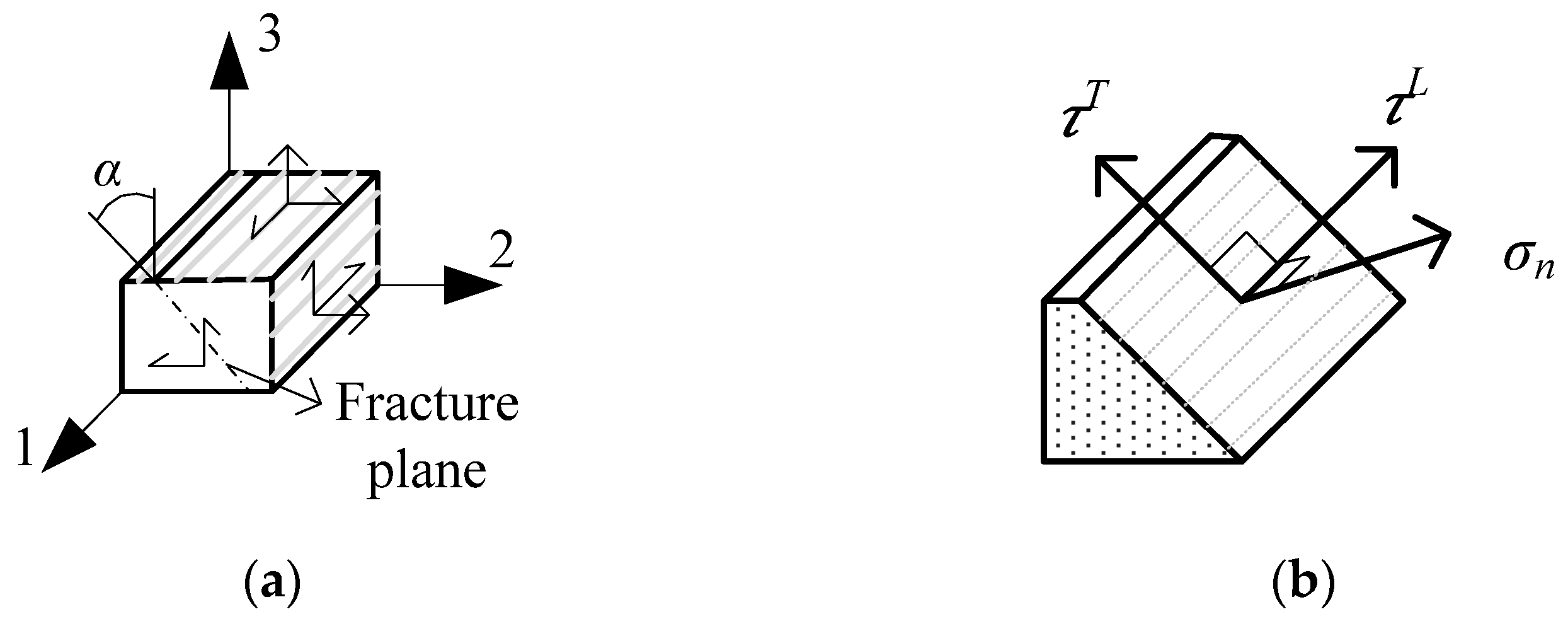
Matrix compression specimens fail by shear, and the geometrical representation of the FRP-laminated fracture plane under compression is shown in
Figure 3a. Moreover, the matrix fracture plane for a 3D stress state is shown in
Figure 3b, along with the corresponding stresses.
Equation (1) represents the expression for the matrix compressive failure condition of LaRC04 failure criteria, along with the description of the symbols used in the expression. Reference [
32] provides further details relating to the symbols used in the expression.
: Matrix failure index;
Normal traction in the fracture plane;
Transverse shear traction in the fracture plane;
Longitudinal shear traction in the fracture plane;
Transverse shear strength;
In situ longitudinal shear strength;
: Transverse friction coefficient;
: Longitudinal friction coefficient.
3.1.2. LaRC04 Failure Criteria for Fiber Kinking Under Compression
The compressive failure in the FRP composite materials is typically in localized bands where fibers are rotated largely, and the matrix is under large shear deformation. This phenomenon is known as the kinking band, as presented in
Figure 4a, with the corresponding misalignment frame. The misalignment angle at failure for pure compression is
. The unidirectional lamina under compression, along with the stress state in the (2,3) plane, is shown in
Figure 4b. The kink plane is at an angle
with plane 2, which depends on the particular stress state.
Equation (2) represents the fiber compressive failure condition of LaRC04 failure criteria, along with the description of the symbols used in the expression. Reference [
32] provides further details relating to the symbols used in the expression.
: Fiber failure index;
: Normal stress in the misalignment frame,
Figure 4a;
: Longitudinal friction coefficient;
: Shear stress in the misalignment frame;
: In situ longitudinal shear strength.
3.2. Damage Propagation
When damage occurs in a composite structure under compressive loading, the material response is modified according to the damage predicted by Equations (1) and (2). The FE simulations based on the progressive damage model, the presence of damage only affects the elastic properties of the specific element, and the stiffness reduction is confined only to the vicinity of that element. The effect of the damage on the stiffness properties of the material is represented by internal state variables, such as tensile (
) and compressive (
) properties degradation [
30].
Furthermore, in this study the CLPT is used to calculate the overall stiffness properties of the laminate and in-plane stresses. As the damage is detected, the material property degradation rules are applied to take into account the post-damage material properties for damaged regions until the global failure of the structure. The problem under consideration is pure compressive in nature; therefore, the matrix cracking and fiber compressive fracture are discussed in detail.
3.2.1. Material Degradation for Matrix Compressive or Shear Cracking
The internal state variables associated with the matrix compressive damage, and the elastic properties (i.e., the elements of the stiffness matrix in terms of
) of the damaged elements are reduced as shown in Equations (3)–(5) [
30,
42]. Reference [
32] provides further details relating to the symbols used in the expression.
3.2.2. Material Degradation for Fiber Compressive Fracture
A similar parametric investigation carried out by Tan et al. [
42] is used to calculate the internal state variable for the stiffness loss due to fiber compressive fracture (
). The elastic property reduction expression for fiber compressive failure is shown in Equation (6).
3.3. Progressive Analysis Methodology Adopted for Post-Buckling Analysis of Laminated FRP Plate Structure
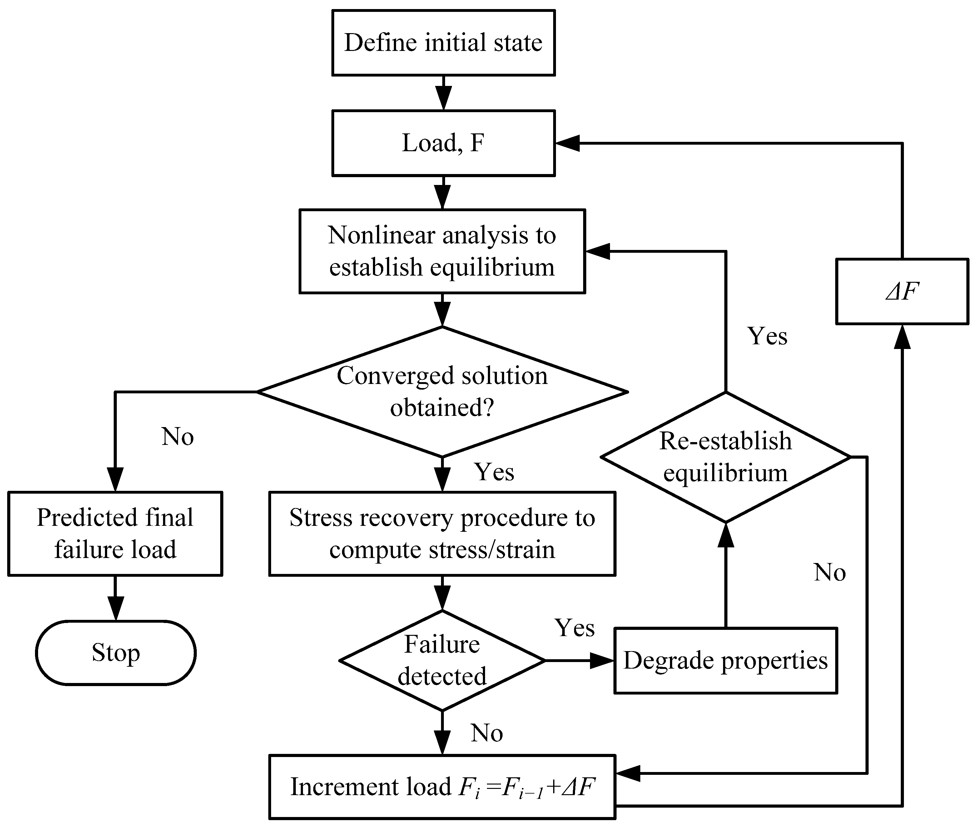
The progressive failure analysis methodology used in this study is illustrated in
Figure 5, which is based on Continuum Damage Mechanics (CDM) [
43]. FE simulations were based on the progressive failure analysis consists of five steps: (1) a nonlinear FE analysis using commercially available software, such as ANSYS; (2) a reliable stress estimation technique to quantify the stresses across the laminate plies; (3) failure criteria to determine the damage initiation; (4) a damage model to estimate new material properties at each load step; and (5) a procedure to re-establish equilibrium with modified material properties.
The compressive load for post-buckling analysis is applied in increments (load steps) on the composite structure until the final structural collapse. Load increments
in small steps are used in the nonlinear analysis procedure, which enhances the possibility of re-establishing the equilibrium during nonlinear analysis. As shown in
Figure 5, at each load step, a nonlinear analysis is performed until a converged solution is obtained, without degrading the material properties.
Afterwards, the stress level within each layer is used to determine the failure initiation in the composite construction as per the used failure criterion. If failure is detected in the material, then the material properties of the composite laminate are degraded according to the degradation model for damage propagation. A nonlinear analysis with modified material properties is performed to establish the equilibrium. The iterations for the nonlinear solution are continued until there is no additional material failure is detected with the change in material model. Finally, the catastrophic collapse resulted from the global structural buckling, and the corresponding load would be the final failure load of the composite construction.
4. Post-Buckling Analysis of a Laminated FRP Composite Plate Structure
The main objective of this research is to examine the use of progressive failure analysis methodology to determine the post-buckling response of a laminated composite plate structure. This study used the progressive failure model available with the ANSYS FE software. The proposed analysis methodology is based on the failure detection, material degradation models to modify material properties when failure is detected, and simulating the catastrophic collapse of the composite construction under compressive loading. The progressive failure model available in ANSYS 2022 R1 (ANSYS Inc., New Castle, DE, USA) is used to predict the damage and response of a laminated composite structure from initial loading to the final failure of the structure.
The composite laminated plate structure under axial compressive loading, proposed by Sleight et al. [
43], is used as a reference model to validate the results of our study.
4.1. Geometry and Boundary Conditions of the Investigated Structure
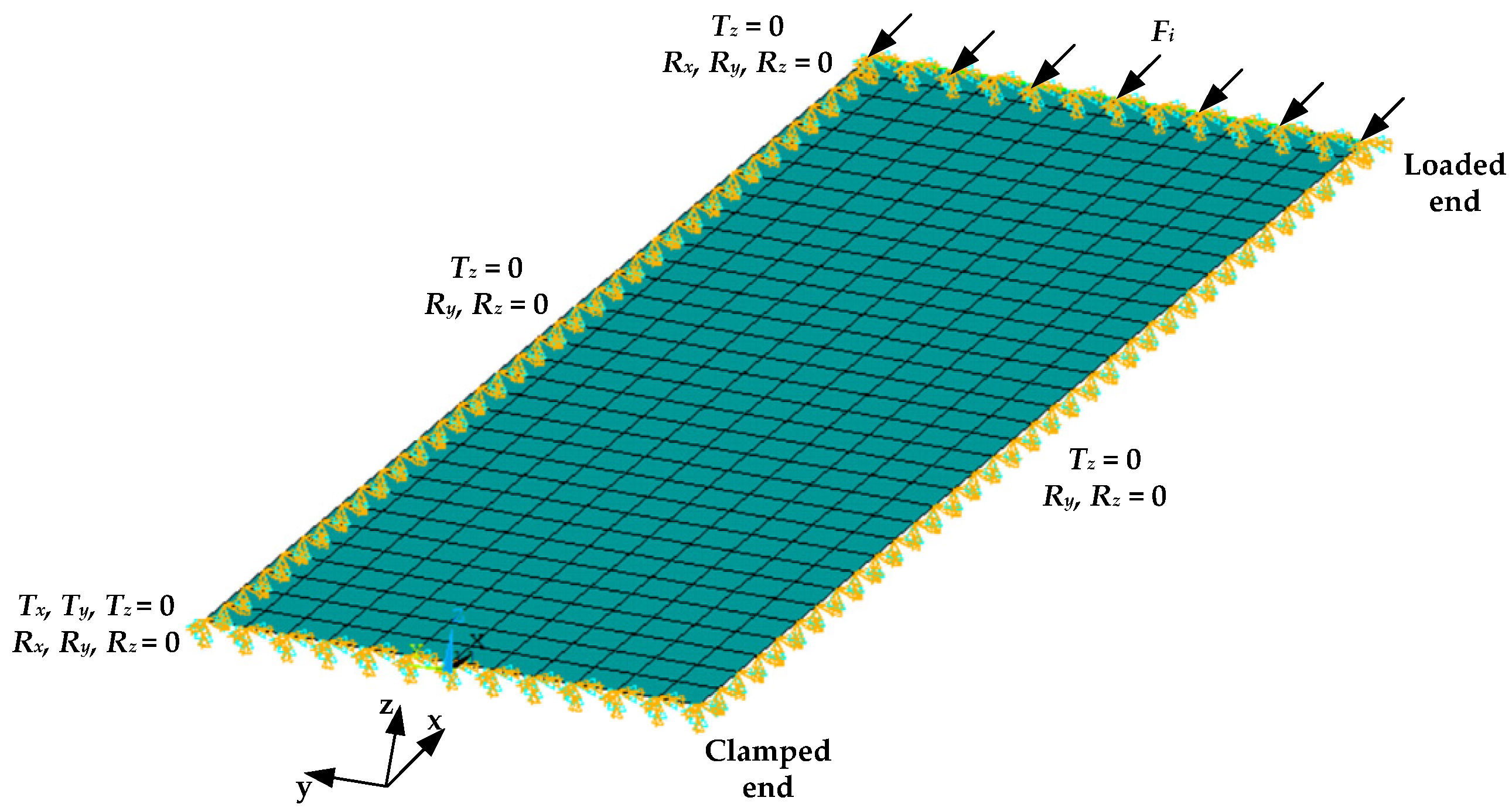
The investigated FRP-laminated structure is a rectangular plate without stiffeners, as shown in
Figure 6. The length of the panel (
l) is 508 mm (20 inches), and the width (
w) is 171.45 mm (6.75 inches).
The clamped boundary condition is applied on the right side of the plate, and a step-wise compressive load
F is applied in the longitudinal direction on the left side of the plate, as seen in
Figure 6. The load is incremented until the plate collapses, to investigate its post-buckling characteristics and determine the ultimate failure load.
4.2. Material Properties and Layup Sequence of the Investigated Laminated FRP Plate Structure
The plate structure uses unidirectional Thornel 300 graphite fiber tapes pre-impregnated with 450 K cure Narmco 5208 thermosetting epoxy resin [
43]. The composite material stiffness properties are shown in
Table 1, and the strength characteristics are shown in
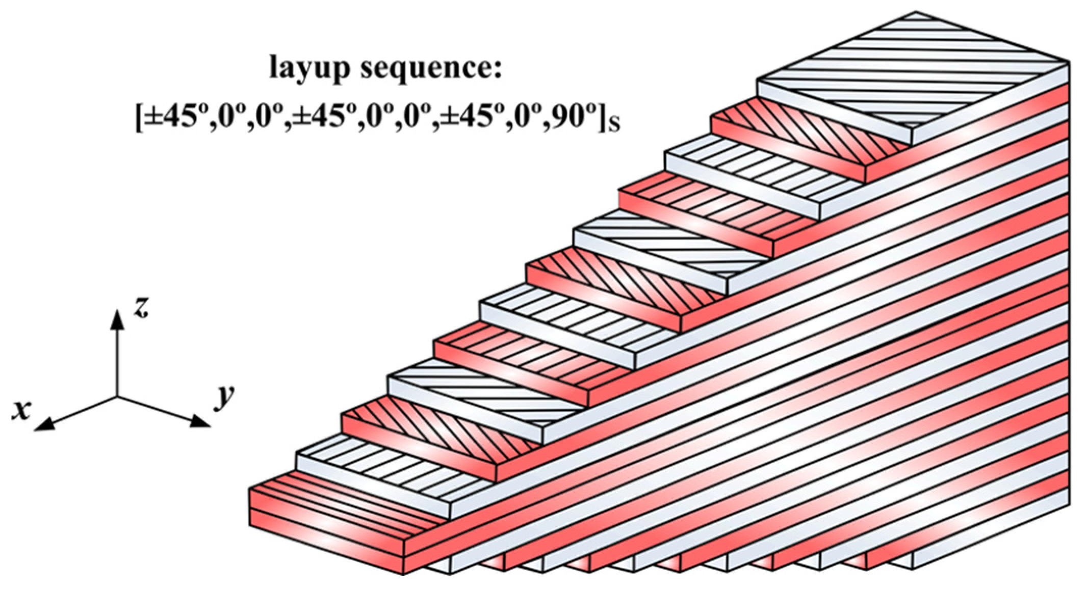
Table 2. The thickness of each ply is 0.14 mm. The investigated plate structure is made of a symmetric layup of 24 ply, and the stacking sequence used is [±45°, 0°, 0°, ±45°, 0°, 0°, ±45°, 0°, 90°]
s as shown in
Figure 7. The total laminate thickness (
t) is 3.36 mm.
4.3. FE Model of the Investigated FRP-Laminated Plate Structure
The FE mesh of the investigated plate structure is shown in
Figure 8. The present study focuses on the global post-buckling response of a thin laminated plate structure; therefore, CLPT provides a computationally efficient and reasonably accurate approximation for out-of-plane deformations. The FE model utilizes a four-node shell element, specifically the SHELL181 element, governed by first-order shear-deformation theory, well-suited for large deformations and strains in nonlinear applications.
A Shell-181 element has 06 DOF at each node, i.e., three translations Tx, Ty, Tz along x, y, z axes, respectively, and three rotations Rx, Ry, Rz about x, y, z axes, respectively. The shell elements comparatively require less time to solve the FE numerical model than the solid elements, which enhances the computational efficiency of the nonlinear analysis.
The plate is divided into 34 elements along the length and 12 elements along the width, as shown in
Figure 8. All the nodes at the clamped end of the plate are constrained in all DOF. An incremental compressive load is applied at the loaded end of the plate, which is clamped in
Tz translations and
Rx,
Ry,
Rz rotations. Moreover, the unloaded ends of the plate are simply supported by knife-edge supports to prevent the panel from buckling as a wide column, i.e.,
Tz,
Ry and
Rz are constrained.
4.4. FE Analysis Procedure of the Laminated FRP Plate Structure
The steps followed to solve the FE model for a nonlinear post-buckling analysis of the FRP-laminated plate structure under consideration are shown in
Figure 9.
The element’s stiffness matrices for finite element analysis were obtained through linear static analysis. The stiffness of the un-deformed structure was taken as the starting point, where the critical loads and buckling shapes were determined by solving an eigenvalue problem using the Block Lanczos method [
44]. To run the linear buckling analysis, a static solution with pre-stress effects was obtained, followed by the eigenvalue buckling solution to determine the critical loads (
) and the corresponding buckling mode shapes.
Small imperfections were imposed on the structure in order to induce the instability. The structure modeled in the finite element environment is “perfect”; therefore, it tends to remain in its initial configuration. This small imperfection can be defined as a small “out-of-plane force” or as a “small imperfection” in the coordinates of the nodes. Here, initial geometric imperfections are formed by using the first 10 buckling mode shapes normalized by their maximum component. Afterwards, scaled by 10% of the panel thickness, these geometric imperfections are added to the nodal coordinates.
To perform the post-buckling analysis, the applied compressive load at the loaded end must be allowed to increase with a small increment (∆F), so that the expected critical buckling load at collapse of the structure is predicted accurately. An elastic nonlinear analysis was performed to assess the structural behavior without any material failure. The numerical solution procedure employs the Newton–Raphson method with automatic load stepping. Furthermore, the NSUBST command in ANSYS is utilized to define the number of sub-steps taken within each load step.
For the progressive failure analysis, ANSYS’s built-in failure models are used. Two material models are used: damage initiation criteria (DMGI) and damage evolution law (DMGE), which are based on the work of Camanho et al. [
30]. DMGI was based on LaRC04 failure criteria to detect the damage.
DMGE was used for damage propagation in the structure as per the degradation law for the reduction in material stiffness parameters at each load step (see
Section 3.2). The valid values for degradation factors range from 0 to 1, where 0 indicates no reduction in material stiffness after damage initiation, and 1 represents complete stiffness loss. In this study, the default ANSYS values are applied. The ANSYS progressive damage model (DMGE) predicts post-damage degradation of brittle anisotropic materials, such as fiber-reinforced composites, at each load step.
5. Post-Buckling Analysis Results of the Investigated Laminated FRP Plate Structure
The ANSYS simulation results for the post-buckling behavior of the laminated FRP composite plate structure were compared with previously published numerical simulations [
43] based on the Hashin failure criteria and experimental results [
45]. This comparison was performed to validate the accuracy and reliability of the progressive damage analysis methodology for predicting the post-buckling response of the plate structure under consideration.
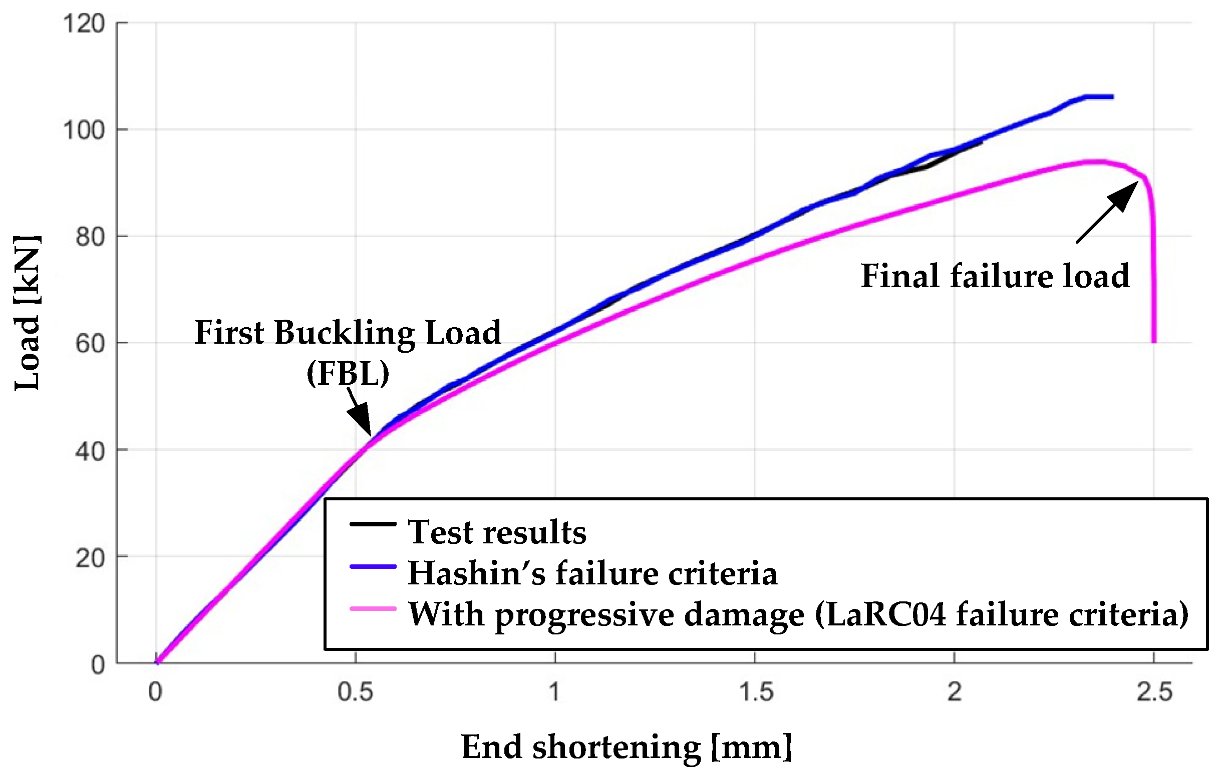
Figure 10 presents the comparison between the simulated and experimental results, illustrating the relationship between plate end shortening (at the loaded end of the plate structure, as shown in
Figure 8) and the applied compressive load.
An abrupt change in the slope of the end-shortening curve reflects the inability of the plate structure to carry additional load, representing the final failure load as shown in
Figure 10. This point corresponds to the onset of global instability, where local post-buckling deformations can no longer redistribute stresses, leading to catastrophic structural collapse.
The first buckling load is indicated at the curve’s neck, where the slope departs from the linear elastic region, representing the onset of local structural instability. The predicted first buckling load by simulation and experimental results is 44.5 kN for the FRP-laminated plate structure, as shown in
Figure 10.
Table 3 summarizes the comparison between the final failure loads predicted by ANSYS simulations based on the LaRC04 and Hashin failure criteria and the corresponding experimental test load extracted from
Figure 10.
Table 3 shows that the failure load predicted by the Hashin failure criteria-based simulation is 104.6 kN, compared to the experimental load of 97.5 kN, representing a 7.2% overestimation. In contrast, the final failure load predicted by the ANSYS progressive failure analysis is 94 kN, which is 3.5% below the experimental value. These results indicate that the ANSYS simulation model provides a more conservative prediction of the post-buckling failure load of the laminated FRP plate structure compared to the Hashin criteria-based approach. In aerospace applications, conservative predictions are generally preferred, as they ensure adequate safety margins and reduce the risk of unexpected structural failures, especially when operating in material nonlinear regions.
At the point of structural collapse, the ANSYS model predicts a maximum end compression of 2.5 mm, slightly higher than the 2.4 mm predicted by Hashin criteria-based simulations (
Figure 10). The close agreement with both experimental results [
45] and Hashin-based simulations [
43] validates the accuracy of the ANSYS simulation approach.
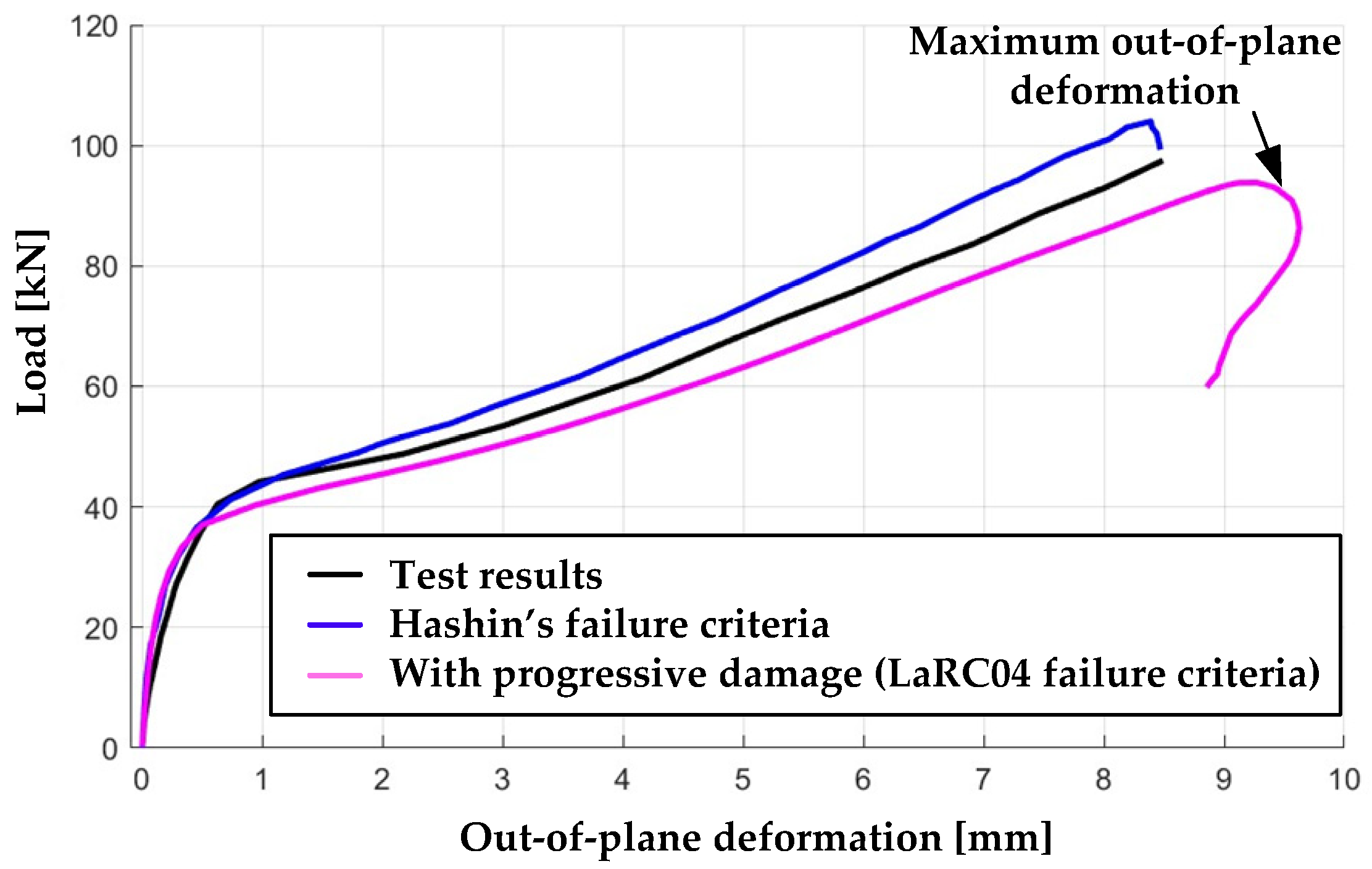
Figure 11 shows the comparison between simulation and experimental results for the plate’s out-of-plane deformation along the
z axis at the point of maximum deflection, plotted as a function of the applied load.
As shown in
Figure 11, the maximum out-of-plane deformations (
z axis) of the FRP-laminated plate at the final failure load are 9 mm, 9.5 mm, and 8.5 mm for Hashin criteria, ANSYS (LaRC04 failure criteria) progressive failure analysis, and experimental tests, respectively. The ANSYS predictions agree reasonably with both the Hashin criteria-based simulations and experimental results.
Figure 12a,b compare fringe plots of out-of-plane deformation at the final failure load for the laminated FRP plate in the post-buckling region, obtained from ANSYS progressive failure simulations (LaRC04 criteria) and Hashin criteria-based simulations, respectively.
The out-of-plane deflection results show a maximum deformation of 9.5 mm according to ANSYS simulations and 9 mm based on simulations using the Hashin failure criterion, occurring at the crest of the buckle. This deformation is approximately three times the original plate thickness (3.36 mm), as illustrated in
Figure 12a,b.
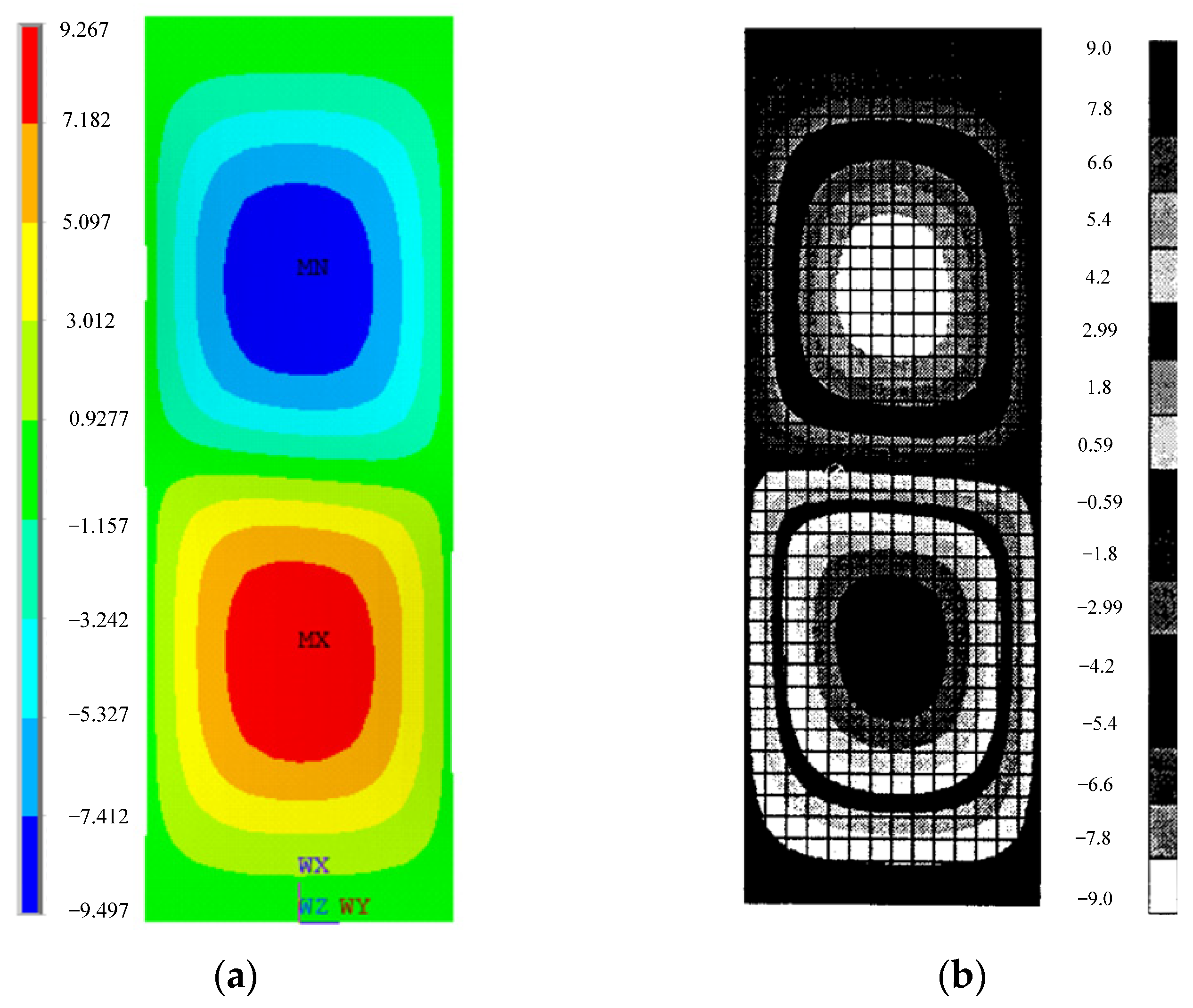
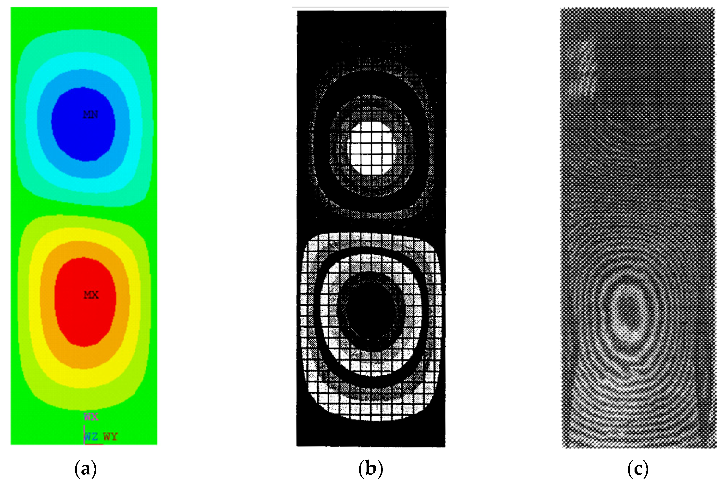
Figure 13 compares the fringe plots at the first buckling load obtained from the ANSYS simulation based on progressive failure analysis (LaRC04 criteria), the Hashin failure criteria-based simulation [
43], and the Moiré-fringe experimental data [
45].
The first buckling mode of the laminated FRP plate structure exhibits two distinct longitudinal half-waves with a nodal line at the panel mid-length, indicating symmetric buckling behavior about the plate centerline. The deformation pattern obtained from the ANSYS simulation (
Figure 13a) closely matches the buckle shape predicted by the Hashin failure criteria-based simulation (
Figure 13b) and the experimentally observed mode shape (
Figure 13c), confirming the consistency of the predicted buckling mode with analytical and experimental results.
Based on a detailed analysis of the results, the proposed progressive failure analysis methodology, incorporating material degradation models, accurately captures the observed failure modes in the post-buckling region, as validated by experimental evidence. This demonstrates the effectiveness of the progressive failure analysis approach in developing reliable and efficient simulation models for composite structures.
6. Conclusions
Fiber-Reinforced Polymer (FRP) laminated plate structures possess significant post-buckling strength reserves that can be utilized to enhance structural efficiency. To fully exploit this capacity, reliable methods are required to accurately predict their nonlinear response, failure modes, and collapse loads, ensuring the safe and efficient design of composite structures.
This study presents an efficient and reliable methodology for post-buckling analysis of a laminated FRP composite plate structure under compressive load, based on a progressive damage model. The progressive failure analysis employs the 3D failure criterion LaRC04 to predict damage initiation and utilizes internal state variables to model damage propagation. The numerical simulations were performed using ANSYS 2021 R2 finite element software.
This research proposed an efficient finite element simulation model employing 2D shell elements based on Classical Laminate Plate Theory to compute the in-plane stresses in an investigated composite plate structure. The use of 2D shell elements, instead of solid elements, significantly reduces computational time while maintaining accuracy, thereby enhancing the overall efficiency of the nonlinear finite element analysis.
The proposed progressive failure methodology accurately predicted the final failure loads of the composite FRP-laminated plate structure. Comparison of the ANSYS simulation results for the final failure load with the experimental results showed only a 3.5% difference. However, Hashin’s failure criteria simulation results showed a 7.2% difference compared to the experimental results. The final failure load predicted by the ANSYS simulation results was lower than the experimental and Hashin’s failure criteria-based simulation results; consequently, the proposed methodology offers a more conservative and reliable prediction of the final failure load of the FRP-laminated plate structure.
The numerical simulation procedure accurately predicted the buckling mode shapes, represented as out-of-plane deformations at both the first buckling load and the final failure load. The fringe plots of the buckling mode shapes showed good agreement with both the Hashin failure criteria-based simulations and experimental results. At the final failure load, the out-of-plane deformations of the laminated FRP plate structure reach approximately three times the original plate thickness. The large post-buckling deformations observed indicate that deformation-sensitive composite structures, such as aircraft wings and tail planes, should be designed to avoid operating in the post-buckling region.
The present study focuses on a simple laminated plate structure under buckling constraints; however, the proposed analysis methodology can be extended to more complex configurations, such as stiffened panels subjected to various loading conditions, in future research to investigate their post-buckling response. Furthermore, experimentally validated simulation data can be integrated into machine learning-based optimization frameworks to generalize and enhance the predictive capability of the proposed methodology for composite structural systems.
The proposed analysis methodology, incorporating both geometric and material nonlinearities, is essential for the design of next-generation laminated FRP composite structures. The proposed FE-based progressive failure analysis provides a robust and efficient framework for accurately predicting nonlinear post-buckling behavior and complex failure modes in composite laminated structures, enabling the design of safe and high-performance lightweight structures.
