Article

Sound-Absorbing Thermoplastic Composite with Helmholtz Resonance

by
Eulalia Gliścińska
1,*,
Marina Michalak
1 and
Anna Michalak
2
1
Textile Institute, Faculty of Textiles and Design, Lodz University of Technology, Zeromskiego Street, No. 116, 90-924 Lodz, Poland
2
Department of Econometrics, Faculty of Economics and Sociology, University of Lodz, Rewolucji 1905 r., No. 41, 90-214 Lodz, Poland
*
Author to whom correspondence should be addressed.
Appl. Sci. 2025, 15(21), 11349; https://doi.org/10.3390/app152111349
Submission received: 3 September 2025 / Revised: 12 October 2025 / Accepted: 17 October 2025 / Published: 23 October 2025
(This article belongs to the Special Issue Research on Polymer Composite Materials)

Abstract

This work concerns a thermoplastic composite manufactured by thermal pressing of a nonwoven layered system. The composite structure consists of two layers: a thicker porous fibrous/plastic layer that responds to sound absorption and a thinner, rigid polymer (plastic) layer on the outside, enhancing sound absorption at selected frequencies. The novelty of this work is the creation of two interconnected holes of different diameters in a real fibrous composite, passing through both composite layers, acting as the neck and cavity of a Helmholtz resonator. Both the neck and the cavity are located within the composite structure, creating the shape of interconnected cylinders. The sound absorption of a composite with a varying neck diameter and a constant cavity diameter was studied using an impedance tube. The effect of the neck diameter on the resonant frequency and the corresponding sound absorption value was investigated. For various neck diameter variants, the resonant frequency was calculated using not constant, but a variable effective neck length. To achieve this, appropriate neck length corrections have been made for each neck diameter. The experimental results are consistent with the calculated results. These studies show that based on the relationship between the resonant frequency and the resonator neck diameter determined for a given composite, the resonant frequency (absorption peak) can be controlled by changing the neck diameter.

1. Introduction

Noise poses a significant risk to human health and should be effectively controlled. Low-frequency sound waves are particularly hazardous to human health and their spread is difficult to minimize using sound-absorbing materials such as foams or fibrous materials [1]. There is a need to use materials designed to absorb sounds within specific frequency ranges or with the widest possible frequency range, or adaptable to a given situation, i.e., a given frequency range, depending on the need. Many developed sound-absorbing materials are homogeneous in structure, e.g., fibrous, foamy or grainy/free-flowing. Due to their homogeneous structure, they are dedicated to absorb a selected range of sound frequencies. However, the range of absorbed frequencies depends on many factors related to the material’s structure, such as thickness, density, or fiber fineness. For example, lower-density aluminum foam has better sound absorption in the lower frequency range, higher-density foam has better sound absorption in the higher frequency range [2,3,4]. Porous sound-absorbing materials and resonant sound-absorbing materials are generally known. The first of them are mainly foams consisting of interconnected cell structures and fibrous materials containing a system of interconnected channels. Porous sound-absorbing materials are characterized by a high degree of sound absorption and a wide range of absorbed sound frequencies. The degree of absorption and frequency range depend, among other things, on the structure of the porous material, i.e., its thickness, frontal surface, and internal porous structure. They are typically used to absorb medium and high frequencies [5,6]. Resonant sound-absorbing materials are mainly perforated panels, membrane absorbers, or single Helmholtz resonators [7,8,9,10]. These materials exhibit internal resonance and therefore have high absorption in a narrow band of sound frequencies. Usually, resonant absorbers are used for absorption of low frequencies [5,11,12]. Some proposed sound-absorbing structures consist of several different layers, either separate or integral [13,14,15]. Typically, one of the separate layers, located on the sound side, is a membrane or a perforated panel. They operate by increased absorption of selected resonant frequencies. The membrane can be, for example, a layer of nanofibers [15]. In integral materials, i.e., composites, the outer layer on the sound side may be a polymer layer with a different structure than the porous part containing, for example, fibers in a polymer matrix [16,17].
A number of metamaterial structures operating on the principle of resonant absorption mechanism have been developed [8,18,19,20]. These structures can be adapted to absorb selected sound frequencies. The authors of some publications propose the combination of perforated panels with porous materials in different arrangements (parallel, series, mixed), different geometric dimensions and different materials of the joined structures [21,22,23]. Systems containing a perforated plate with an air cavity, a cavity filled with a porous material, or an acoustic black hole are often proposed [13,22,24,25,26]. According to the literature on this subject, the thickness of such metamaterials usually oscillates in the range of at least several dozen millimeters [8,19,21,23,24,27,28]. In the case of an ultrathin acoustic absorbing metasurface, the thickness can be 1.3 cm [29]. Usually, perforated panels are plates with cylindrical holes or curved at a specific depth to form cavities [23,24,27]. Research most often involves simulations and theoretical considerations, as well as experimental verification based of model samples. Model samples for experimental studies are specially manufactured to precisely reproduce the material and geometric assumptions of the proposed system. The most commonly used layers of the system are foams (melamine, polyurethane) [21,23] and microperforated panels made of metal, plywood, cardboard, or plastic sheets obtained by additive manufacturing, i.e., 3D printing (photosensitive resin, thermoplastic polymers, e.g., PLA, nylon with carbon fibers) [9,14,19,20,21,23,24,29,30].
Some sound-absorbing materials contain structures that operate on the principle of Helmholtz resonance. This phenomenon, named after the German physicist Hermann von Helmholtz, involves the vibration of the air inside the cavity at a specific natural frequency. A Helmholtz resonator consists of a neck and a cavity. Their material, shapes and dimensions determine the sound absorption performance and the resonant frequency at which the resonator naturally oscillates [31,32,33,34]. This occurs when airflow disturbs the air mass vibrating in the neck, which begins to oscillate and then excites the air resonance in the cavity. In acoustics, this type of resonance is unique because it is characterized by a sharp and high-amplitude resonance curve [31,35]. The literature suggests that the resonance model in a spherical resonator is differs for short and long necks. Calculating the resonance frequency of a specific Helmholtz resonator requires consideration of the cross-sectional area and length of the neck, as well as the cavity volume. In the models, the neck length differs from the geometric length and is described by the effective length, which introduces a correction. However, applying the same neck length correction value for different resonators in theoretical studies to date has been inappropriate [36].
The maximum efficiency of a resonator is achieved only at the resonant frequency depending on its size. Therefore, in the case of a panel containing resonators of uniform size, the performance over a wide frequency range is insufficient. Each resonator in the panel must be appropriately sized to extend the frequency range of sound absorption [37]. The use of gradually perforated holes in the rigid sample connected to the cavity also increases broadband sound absorption [38]. Publications describe the occurrence of Helmholtz resonance phenomenon in systems tested in an impedance tube, where a rigid layer of material located on the side of the sound wave has a perforation, and from the back is connected by a tube with another material or the back wall of the tube, creating an air cavity. The holes forming the perforation in the front layer act as necks, while the back space acts as an air cavity. The effect of the presence of a Helmholtz resonator, as well as the effect of cavity parameters, e.g., cavity depth, and perforated panel parameters, such as panel thickness, perforation coefficient, hole size and topology, on the sound absorption of the entire system was analyzed [35,39,40,41,42,43]. However, the Helmholtz resonance phenomenon has not been studied in a fibrous composite, which is a porous sound-absorbing material.
The sound absorption coefficient tests using an impedance tube presented in this article apply to a real composite material obtained in a pressing process. The composite is fibrous because the fibers act as a reinforcing component, and thermoplastic because its matrix is a thermoplastic polymer. The composite with a two-layer structure, constituting an integral whole, consists of a thicker fibrous/plastic layer, which is responsible for sound absorption, and a thinner plastic layer smooth on the surface and enhancing the absorption of sound at selected frequencies. To increase the sound absorption of this composite material, an artificial Helmholtz resonator was created within it. Unlike systems described in the literature, the composite is not connected to an air cavity, and its back wall is in contact with the rigid wall of the impedance tube during sound absorption testing. Therefore, both the neck and the cavity of the Helmholtz resonator are located within the material. The neck is located in a smooth plastic layer facing the incident sound wave, while the cavity is located in the back layer, i.e., fibrous/plastic layer. The object of acoustic research was therefore both the fibrous sound-absorbing material and the Helmholtz resonator as one integral material, which is not described in the literature. The effect of the dimensions of the neck of the Helmholtz resonator on the change in the resonant frequency and the corresponding sound absorption value was investigated. Such a relationship has not been studied so far for the cylindrical shape of the neck and cavity. The results obtained for the real fibrous composite were related to the theory of the Helmholtz resonance phenomenon. A significant advance in composite materials and acoustic research was the demonstration of the relationship between the effective neck length and its diameter. This required the appropriate selection of different neck length correction values depending on the neck diameter, which has not been used before. According to literature reports [36], this correction should be selected individually for each specific Hemholtz resonator. It is also worth emphasizing that the developed material is rigid and has a small thickness of the order of only a few millimeters, in comparison to those described in the literature. In real conditions, it can be installed in combination with a wall or other rigid material. The components of the composite are of natural origin and environmentally friendly. The subject of the article is in line with the Sustainable Development Goals.

2. Materials and Methods

2.1. Composite Manufacturing

The thermoplastic composite material was formed by pressing a layered package of textile material, i.e., nonwoven. In order to manufacture needle-punched nonwoven the fleece with a transverse-system of fiber arrangement was obtained on a Befama (Bielsko-Biala, Poland) laboratory roller carding machine with an elastic covering, equipped with an Asselin (Paris, France) horizontal stacker. Then, the fleece was needle-punched on an Asselin machine with an upper needle plate, with following technological parameters: type of needles—15 × 18 × 40 × 3 ½ RB (Groz-Beckert®, Germany); needle density—9, 5; number of needle punches—40/cm2; depth of needle punching—12 mm. Two types of nonwoven were manufactured. The main nonwoven was produced from mix of fibers, i.e., reinforcing fibers and thermoplastic fibers. The second one, the single-component nonwoven, was produced from only thermoplastic fibers.
As reinforcing fibers the waste flax fibers (LI), from Safilin Ltd., Milakowo, Poland, were used. As thermoplastic fibers the polylactide (PLA) fibers characterized by a linear density of 6.7 dtex and a length of 60 mm, supplied by the Far Eastern Textile Ltd. (Taiwan), were used. All the above fibers, obtained from natural raw materials, were selected in order to produce an environmentally friendly composite material.
Composite was formed from a nonwoven layered system in a hydraulic press machine, Hydromega sp. z o.o., Gdynia, Poland, with heated top and bottom plates and water cooling system. The package in the closed form of the press machine was heated to the pressing temperature, which corresponded to the melting point of the PLA fibers. Then, the consolidation stage involved a pressure of 0.58 MPa for 5 min, and finally a cooling stage to ambient temperature.
The main part of the package consisted of layers of LI/PLA nonwoven. The top of the package consisted of layers of thermoplastic fiber nonwoven to create the surface plastic layer. As our previous research has shown [16,17], this layer is desirable in fibrous sound-absorbing materials, because its presence significantly increases the absorption of sound by the material.

2.2. Measurements

The mass per square meter of nonwovens was determined according to the ISO 9073-1:2023 standard [44]. The thickness of the composite material was measured using a micrometric screw. In order to measure the thickness of the plastic surface layer, it was mechanically separated from the fibrous/plastic part. Density was calculated as the ratio of mass to volume of the sample. The sound absorption coefficient of the composite material was determined using an impedance tube, the so-called Kundt tube, type 4206 (Bruel & Kjaer, Nærum, Denmark) with two 1/4-inch condenser microphones type 4187, Figure 1. The physical sound absorption coefficient of 0 to 1 (the ratio of the sound power penetrating through the surface of the tested sample (without return) to the sound power of the plane wave incident perpendicularly on the sample) was determined in accordance with the ISO 10534-2:2023 procedure [45] in the frequency range of 500–6400 Hz. In this method a small tube (diameter 29 mm) is connected to a sound source on one side and a test sample is placed on the opposite side. The noise source generates flat waves in the tube directed perpendicular to the surface of the sample. The sound pressure is measured by two microphones placed in the tube wall. The signals are then transmitted to the analyzer and the distribution of the field disturbances is determined. On this basis, the sound absorption coefficient is calculated. A circular test sample with a diameter of 29 mm was cut out using a metal die under pressure.

3. Helmholtz Resonance

Resonance is a phenomenon that causes a system to vibrate at a frequency equal to the natural frequency of the oscillator. One of the most basic acoustic resonant structures is the Helmholtz resonator, consisting of a cavity connected by a neck to an open space, Figure 2a.
A classical theory approximates the Helmholtz resonator to a spring-mass damper system and provides expressions for the resonant frequency.
A resonant system is characterized by the elasticity of the air stored in a cavity of volume V and the inertia of air with mass M accumulated in the neck. The resonant frequency of the Helmholtz resonator depends on its geometry, i.e., the neck length (L1), the neck cross-sectional area (S) and the cavity volume (V). A simplified formula for the resonant frequency of a single resonator is as follows:
f H   =   c 2 π   S V · L 1
where
fH—resonant frequency;
c —speed of sound in air.
Formula (1) refers to an ideal resonator, while in real situations there are always deviations due to the inaccuracy of geometric dimensions and properties of the material from which the resonator is made. In the composite material, the geometry of the Helmholtz resonator differs significantly from the geometry of the ideal resonator. First of all, due to the fact that it is not an isolated device, but it is produced in a volume of material and forms one whole with it. The neck in an ideal Helmholtz resonator is long compared to the cavity, while in our tested composite it is a hole in a thin plastic layer. Therefore, a correction of the neck length is needed, and the Formula (1) takes the form:
f H   =   c 2 π   S V · L e f f
where
L e f f —effective neck length.
Leff is very important for the accurate determination of the resonant frequency. It expresses the actual L1 increased by a small additional length, the so-called final correction (ΔL), i.e., corrections resulting from the acoustic effect (apparent increase in the neck length as a result of a covibrating air mass outside the neck outlet). At the ends of the neck, the air does not stop moving suddenly, instead a certain amount of air right at the resonator inlet also oscillates, acting as an additional amount of air. This phenomenon causes that in the resonator the length of the neck is described by a higher value than its physical length. The size of the required correction depends on the geometry around the hole and requires numerical calculations. For a resonator with cylindrical geometry (the cavity and neck are made as connected cylinders), the Formula (2) can be rearranged to:
f H   =   c 2 π π r 1 2 π r 2 2 · L 2 · L e f f
where
L 2 —cavity length;
r 1 —neck radius;
r 2 —cavity radius;
Leff = L1 + ΔL.
For a resonator with inverse geometry, when the neck diameter (d1) is larger than the cavity diameter (d2), i.e., the inverted Helmholtz resonator, (Figure 2b), the formula for the resonant frequency is the same as in a classical Helmholtz resonator. However, the roles of mass (air in the resonator neck) and the spring (the air enclosed in the cavity) are reversed.
For a specific composite geometry operating on the principle of the Helmholtz resonance phenomenon, the resonance frequency can be estimated [31,34,35,43,46,47,48,49].
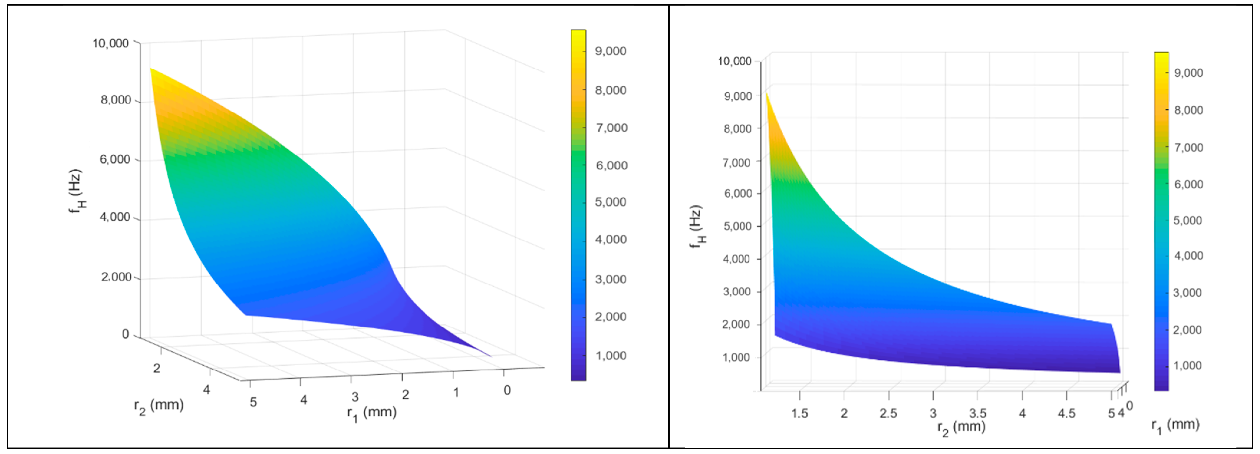
Figure 3 below shows graphically the dependence of fH on r1 and r2 for a composite with a plastic layer thickness of 0.25 mm (L1) and a fibrous/plastic thickness of 4.75 mm (L2), calculated on the basis of Formula (4):
f H   =   c 2 π r 1 2 r 2 2 · 4.75 · ( 0.25   +   1.7 r 1 )
These three-dimensional diagrams for one sample composite serve as illustrations and are presented in several perspectives. According to the literature [43,47], ΔL is determined empirically, and often in publications authors assume ΔL = 1.7r1. The diagrams shown in Figure 3 refer to the correction ΔL = 1.7r1.
As can be seen in Figure 3, fH of the composite is a function of r1 and r2 at given values of L1 and L2 and given ΔL.

4. Results and Discussions

As a result of pressing a package of eight layers of mixed nonwoven fabric (reinforcing fibers and thermoplastic fibers), each with a surface weight of 175 g/m2, and two layers of nonwoven fabric made only of thermoplastic fibers, each with a surface weight of 162 g/m2 applied to them, a composite with a two-layer structure was obtained. The thicker composite layer, 4.75 mm thick, constituted the fibrous/plastic part, while the thinner layer, 0.25 mm thick, constituted the plastic part. The density of the resulting composite was 0.35 g/cm3.
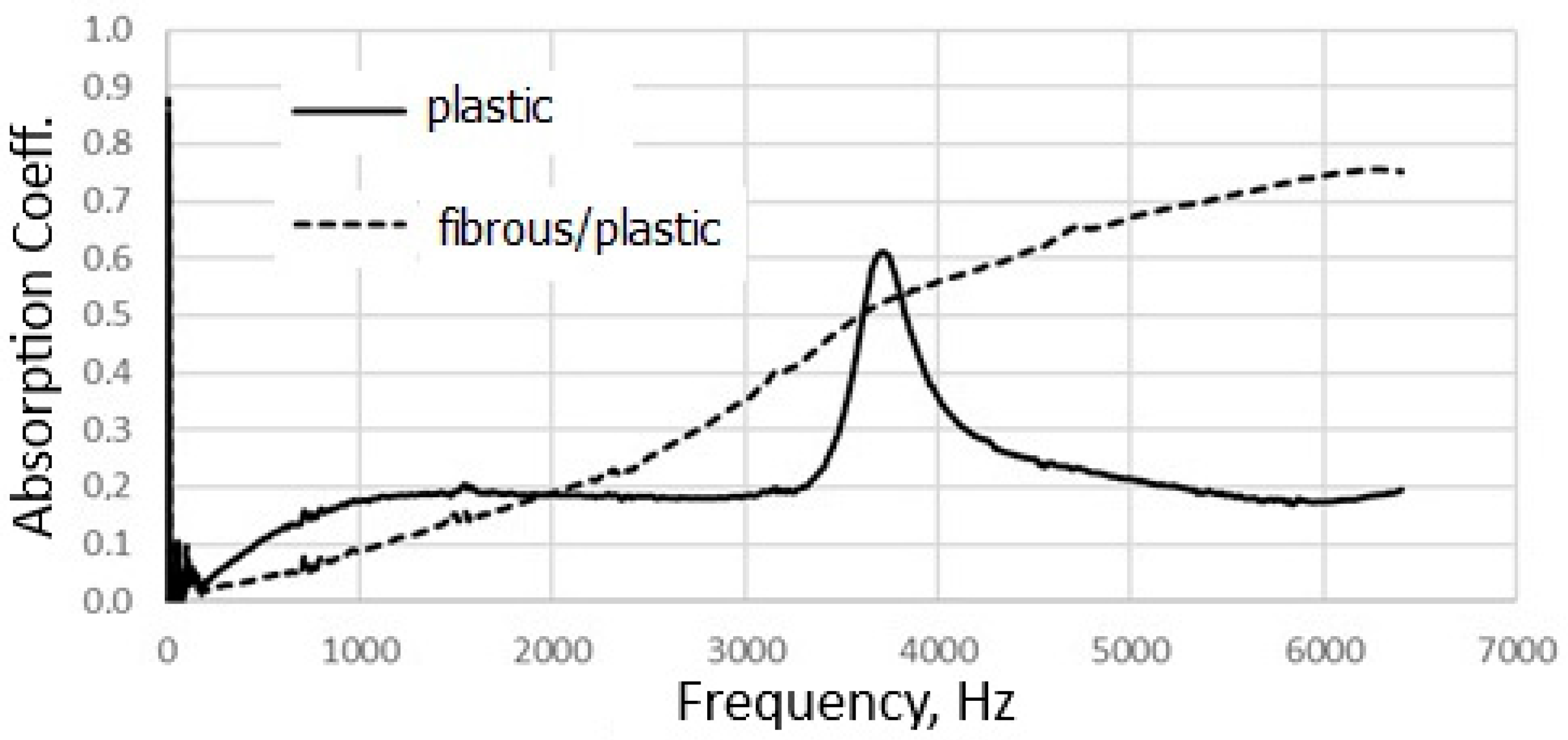
The differences in the acoustic properties of both sides of the composite are presented in Figure 4. Positioning the composite with a fibrous/plastic layer with the front end to the incident sound wave results in the dependence of the absorption coefficient on the sound frequency typical for porous fibrous materials [50]. In the sound frequency range under study, the absorption coefficient increases in direct proportion to the increase in frequency. This relationship is also observed when the through hole acting as a Helmholtz resonator in the composite is made, Figure 5. On the other hand, by positioning the composite with a plastic layer facing the incident sound wave, the sound absorption mechanism changes. A sharp peak is clearly visible, indicating a significant increase in the value of the sound absorption coefficient in a narrow frequency band, Figure 4. A similar effect is achieved for resonating sound absorption structure, containing, e.g., a perforated plate, nanofiber membrane, and a cavity [51,52].
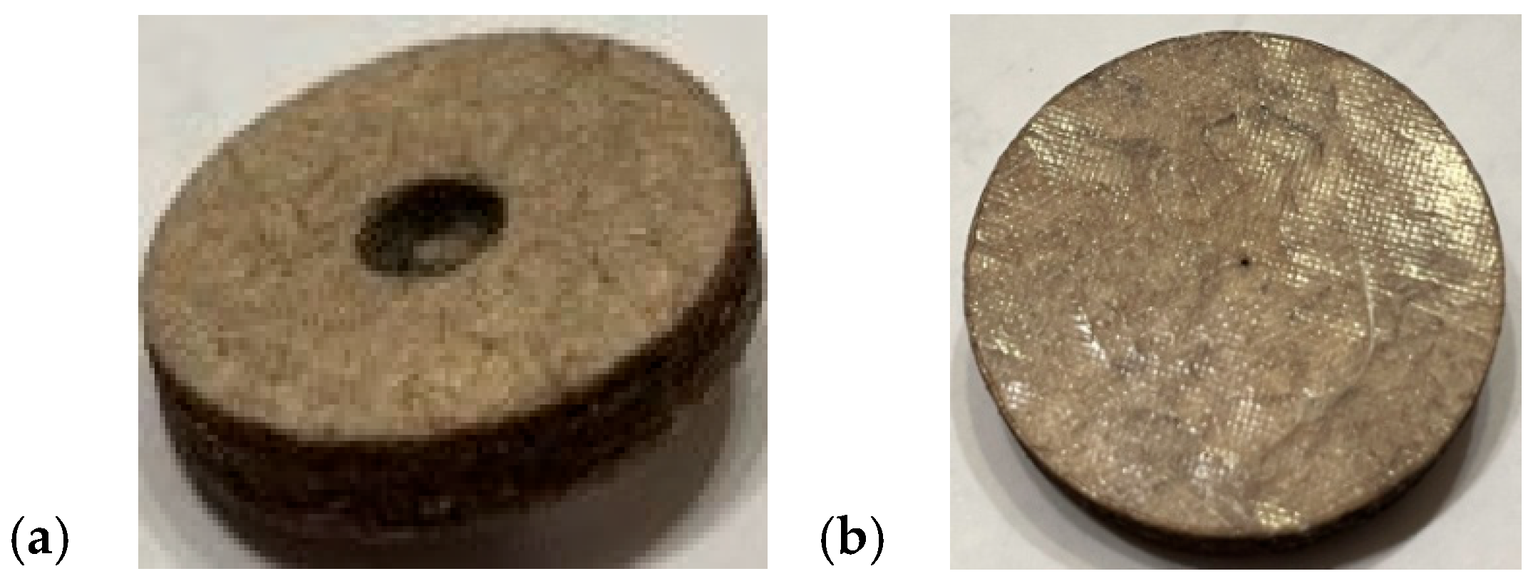
In order to obtain the Helmholtz resonance effect, according to the theory of this phenomenon, a through hole was cut in the central part of the composite sample using a laser beam. The part of the hole along the length equal to the thickness of the plastic layer was the neck of the Helmholtz resonator, while the part of the hole along the length equal to the thickness of the fibrous/plastic layer was the resonator cavity. The diameter of the hole along the entire thickness of the plastic layer was (d1), and the diameter of the entire thickness of the fibrous/plastic layer was (d2). A photo of a composite sample with a hole cut out to reproduce the Helmholtz resonator is shown in Figure 6.
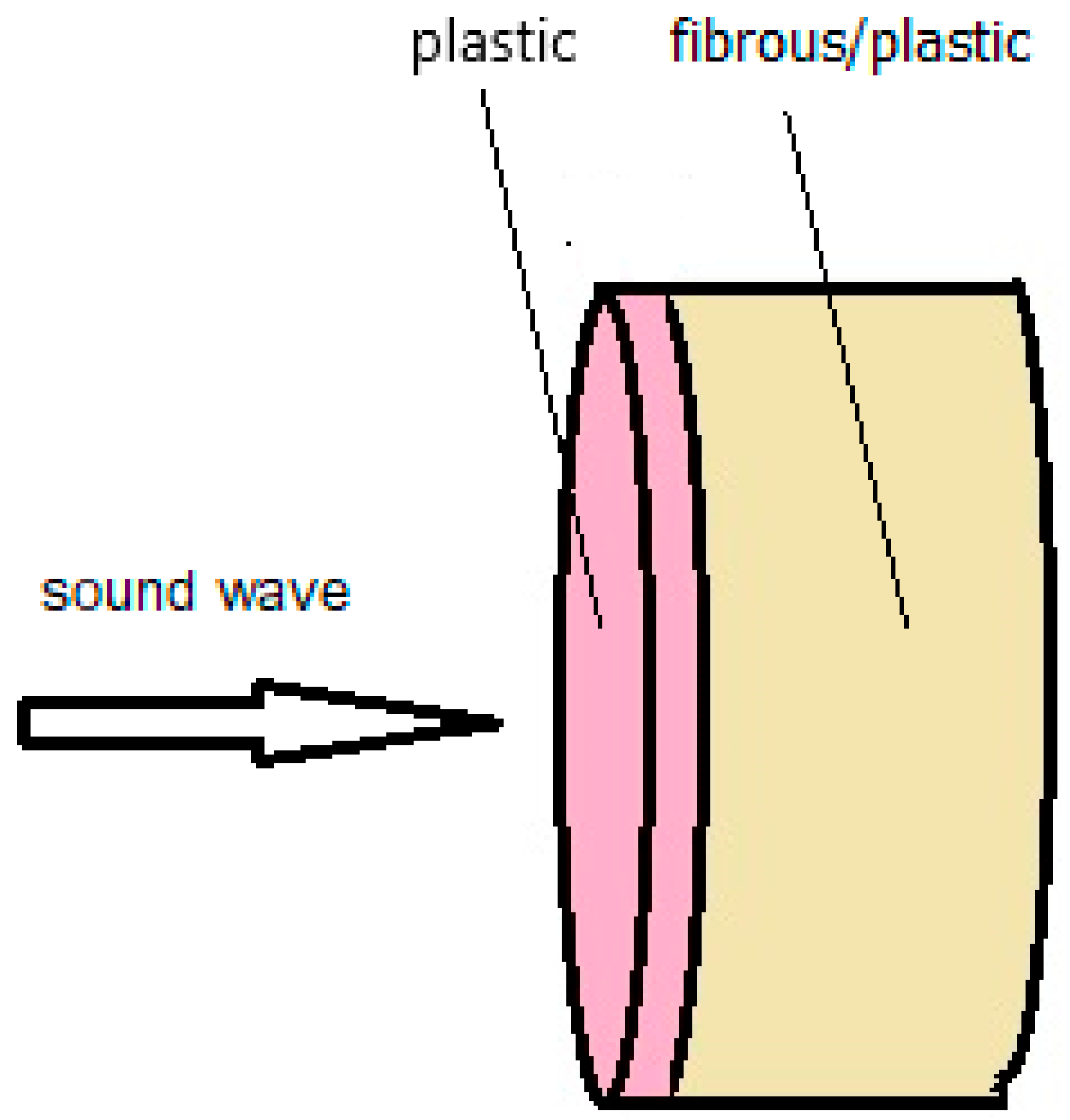
In further investigations, the composite sample was placed in the impedance tube with a plastic layer for the incident sound wave, Figure 7. The fibrous/plastic layer was in contact with the back wall of the impedance tube.
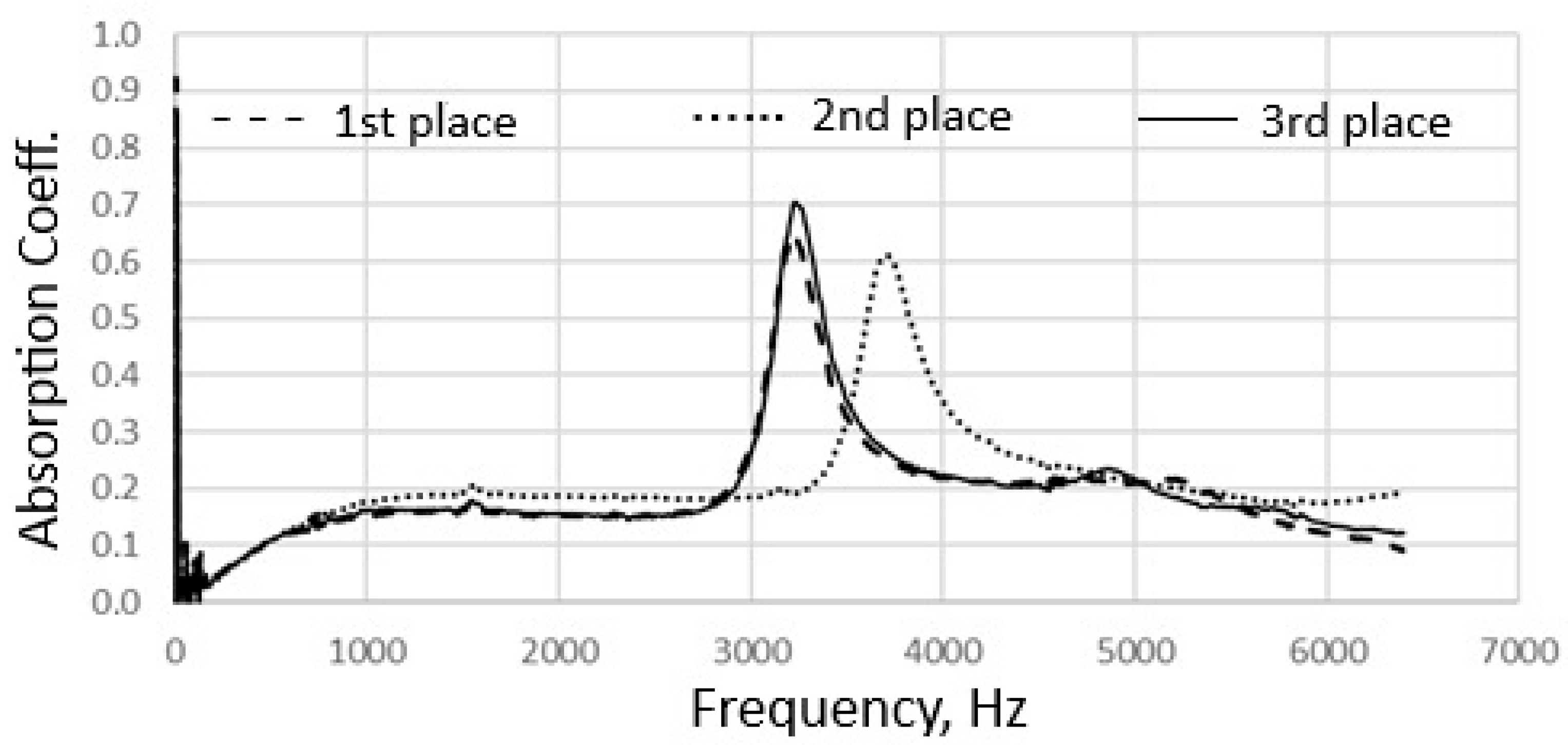
A fibrous composite, like any fibrous material, is characterized by uneven structure. Investigation of samples taken from different places in the material may involve testing a slightly different material structure. Due to the fact that the structure of the actual fibrous composite is not identical throughout the volume, the absorption coefficient-frequency relationship curve for samples cut close to each other may differ slightly, Figure 8.
The composite with a hole acting as a Helmholtz resonator was tested on the same sample after each successive increase in the hole diameter in the plastic layer. The test on the same sample was intended to demonstrate the effect of the hole diameter on the composite’s sound absorption. In all measurement variants d2 was 5 mm, while d1 was changed incrementally.
A diagram of a composite sample with d1 smaller than d2 is shown in Figure 9a. The value of d1 was 0.25 mm, 1 mm, 2 mm, and 3 mm, respectively. A diagram of a composite sample with d1 equal to d2 is shown in Figure 9b. The hole diameter in both layers was 5 mm.
A diagram of a composite sample with d1 larger than d2 is shown in Figure 9c. The value of d1 was 7 mm and 10 mm, respectively.
For comparison, the sound absorption coefficient test was also performed for the composite sample before the hole was cut, Figure 10. The output sample without a hole is characterized by high sound absorption in a narrow frequency range, with a maximum of 3500 Hz. This sharp absorption peak is related to the presence of a rigid plastic composite layer on the side of the sound wave.
The differences in the dependence of the sound absorption coefficient value on the sound frequency for individual variants of d1 < d2 in the composite are shown in Figure 10 and of d1 = d2; d1 > d2 in Figure 11.
All the above graphs of the dependence of the sound absorption coefficient on the sound frequency for a composite with a through hole refer to only one dimension of d2.
On the obtained graphs illustrating the dependence of the sound absorption coefficient on the sound frequency, the high, narrow absorption peak observed for the d1 < d2 variants begins to expand when d1 equalizes with d2 and further when d1 > d2. This high sound absorption, initially observed at a sound frequency of approx. 3500 Hz, caused by the presence of a rigid plastic layer in the composite, in the situation of creating a through hole changing the structure of the composite, moves slightly towards higher frequency values maintaining high sound absorption values over an increasingly wider range. A further increase in d1 causes a further slight shift in the absorption peak towards higher frequencies, i.e., over 4000 Hz, and a slight increase in the sound absorption coefficient from approx. 0.65 to approx. 0.75.
In addition, the graphs show an increase in sound absorption at high frequencies as d1 increases. This indicates that each subsequent change in the structure of the composite caused by a change in the geometry of the through-hole changes the properties of the composite and affects the frequency range of high sound absorption throughout the tested range.
However, the formation of a through-hole acting as a Helmholtz resonator primarily causes the formation of the Helmholtz resonance phenomenon, which is visible to the tested composite in the low frequency range. An increase in d1 of the Helmholtz resonator, results in a shift in this resonance towards higher frequencies, i.e., from 1500 Hz to 3000 Hz. Moreover, as the resonance frequency increases, the corresponding sound absorption coefficient increases, i.e., from 0.2 to 0.5.
The above phenomenon, which is shown as the first peak from the left on the graphs of the dependence of the sound absorption coefficient on the sound frequency, occurs both when d1 is less, equal to, or larger than d2. This phenomenon occurs for the developed composite both when we produce a structure corresponding to the Helmholtz resonator and a structure with inverse geometry when d1 is larger than d2, corresponding to the inverted Helmholtz resonator.
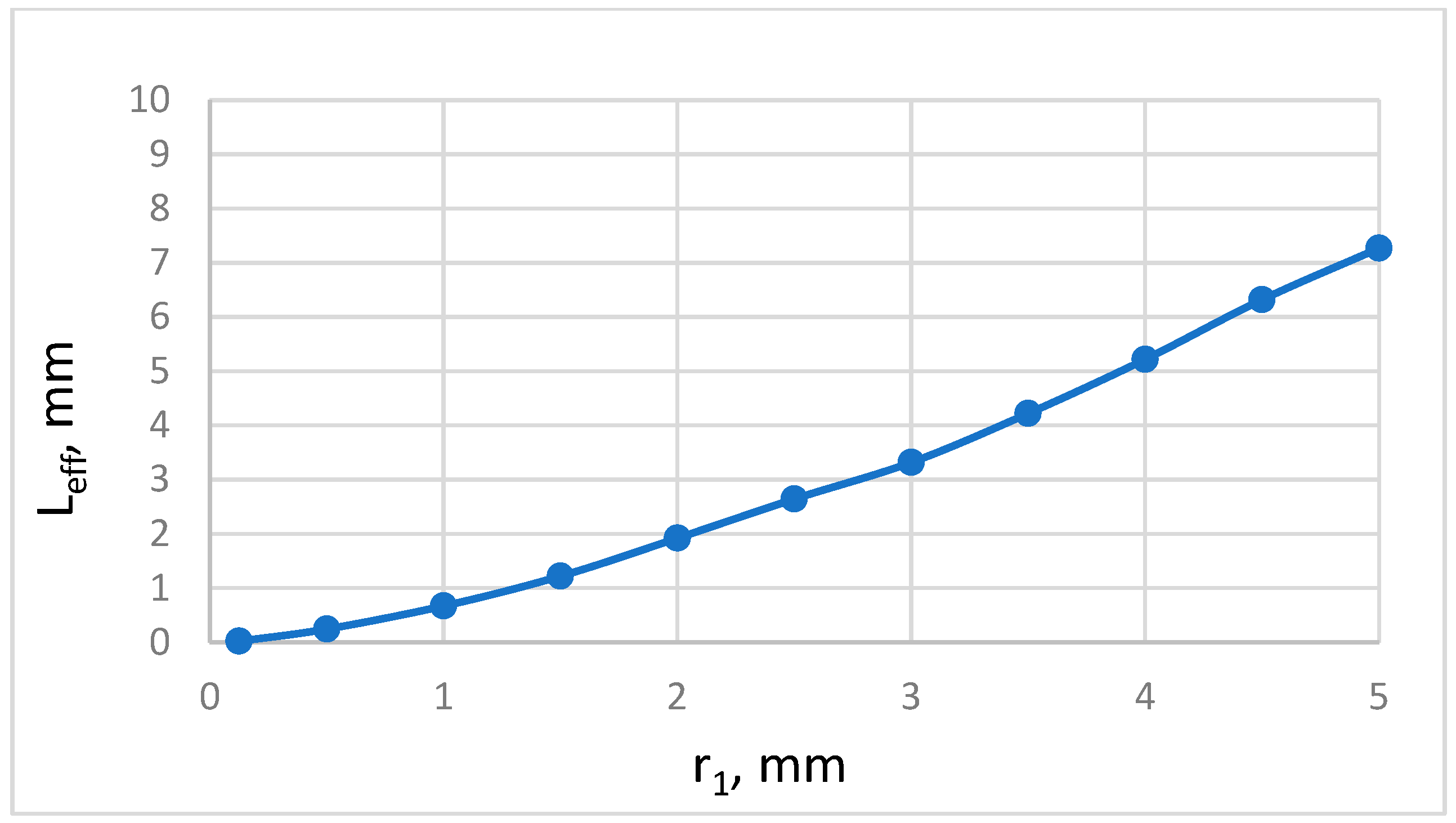
Unlike the results presented in Figure 3, for the tested composite for individual variants of d1, corrections ΔL were assumed. Then, the dependence of Leff on d1 was illustrated, as shown in Figure 12.
On this basis, not limiting ourselves to just one Leff value, but using different Leff values depending on d1, the fH values for each case of d1 were calculated.
As shown in Figure 13, the fH values calculated and determined experimentally for each d1 variant overlap. This demonstrates the feasibility of designing a composite structure that provides a specific fH.
The results show that as the diameter of the resonator neck increases, the resonance frequency increases.

5. Conclusions

In the thermal pressing process of fibers used in the form of appropriately prepared textile materials, a sound-absorbing thermoplastic composite was produced. Its structure consists of a thinner plastic layer and a thicker fibrous/plastic layer forming an integral whole.
Making a hole in the composite passing through both layers and placing the composite with the plastic side to the incident sound wave causes sound absorption also through the Helmholtz resonance phenomenon. If a specific structure acting as a Helmholtz resonator with cylindrical geometry is created in the composite (the cavity and the neck of the resonator are made in the form of connected cylinders of different diameters), it is possible to estimate the resonance frequency. For different neck diameters, the empirical results of resonance frequency were consistent with those calculated using the assumed values of the effective neck length Leff.
Based on the relationship between the resonant frequency and the resonator neck diameter determined for a given composite, the resonant frequency (absorption peak) can be controlled by changing the neck diameter.
With constant resonator cavity dimensions, widening the resonator neck, i.e., increasing the diameter of the hole with a length equal to the thickness of the plastic layer, results in increased sound absorption at the resonant frequency and shifting the resonant frequency toward higher values.

Author Contributions

E.G. contributed to conceptualization, preparation of materials, investigation, theoretical part, visualization, data curation, writing, editing; M.M. contributed to conceptualization, preparation of materials, investigation, theoretical part, visualization, data curation, software, calculations, writing, editing; A.M. contributed to preparation of three-dimensional diagrams, visualization, software, data curation. All authors have read and agreed to the published version of the manuscript.

Funding

This research received no external funding.

Institutional Review Board Statement

Not appliable.

Informed Consent Statement

Not applicable.

Data Availability Statement

The original contributions presented in the study are included in the article. Further inquiries can be directed to the corresponding author.

Conflicts of Interest

The authors declare no conflicts of interest.

References

  1. Azimi, M. Noise reduction in buildings using sound absorbing materials. J. Archit. Eng. Technol. 2017, 6, 198. [Google Scholar] [CrossRef]
  2. Miodragović, T.; Erić-Cekić, O.; Radičević, B.; Grković, V. Composite materials that are good sound absorbers. In Proceedings of the X International Conference “Heavy Machinery-HM 2021”, Vrnjačka Banja, Serbia, 23–25 June 2021. [Google Scholar]
  3. Sikora, J.; Turkiewicz, J. Sound absorption coefficients of granular materials. Mech. Control 2010, 29, 149–157. [Google Scholar]
  4. Yahya, M.N.; Chin, D.D.V.S. A Review on the potential of natural fibre for sound absorption application, International Research and Innovation Summit (IRIS2017). IOP Conf. Ser. Mater. Sci. Eng. 2017, 226, 012014. [Google Scholar] [CrossRef]
  5. Cao, L.; Fu, Q.; Si, Y.; Ding, B.; Yu, J. Porous materials for sound absorption. Compos. Commun. 2018, 10, 25–35. [Google Scholar] [CrossRef]
  6. Egab, L.; Wang, X.; Fard, M. Acoustical characterisation of porous sound absorbing materials: A review. Int. J. Veh. Noise Vib. 2014, 10, 129–149. [Google Scholar] [CrossRef]
  7. Huang, S.; Fang, X.; Wang, X.; Assouar, B.; Cheng, Q.; Li, Y. Acoustic perfect absorbers via Helmholtz resonators with embedded apertures. J. Acoust. Soc. Am. 2019, 145, 254–262. [Google Scholar] [CrossRef]
  8. Wang, D.; Xiao, Y.; Wang, S.; Huang, Z.; Wen, J. Ultra-broadband sound-absorbing metastructure with Helmholtz resonator and porous material modulation crown. Mater. Des. 2024, 246, 113351. [Google Scholar] [CrossRef]
  9. Duan, M.; Yu, C.; He, W.; Xin, F.; Lu, T.J. Perfect sound absorption of Helmholtz resonators with embedded channels in petal shape. J. Appl. Phys. 2021, 130, 135102. [Google Scholar] [CrossRef]
  10. Yu, W.; Zhang, X.; Dong, Q. Application of microperforated-panel absorber in communication products. J. Appl. Math. Phys. 2018, 6, 51–57. [Google Scholar] [CrossRef]
  11. Ye, C.; Liu, X.; Xin, F.; Lu, T.J. Underwater acoustic absorption of composite anechoic layers with inner holes. J. Vib. Acoust. 2019, 141, 041006. [Google Scholar] [CrossRef]
  12. Wang, L.B.; Song, C.H.; Wu, J.H. Reducing cavity dependence in helmholtz resonators via compact neck arrays. Appl. Acoust. 2026, 242, 111070. [Google Scholar] [CrossRef]
  13. Liang, X.; Liang, H.; Chu, J.; Jin, F. Sound absorber based on a sonic black hole and multi-layer micro-perforated panels. Phys. Scr. 2024, 99, 065960. [Google Scholar] [CrossRef]
  14. Zhang, P.-F.; Li, Z.-H.; Zhou, Y.-J.; Zhang, Q.-F.; Liu, B.; Liu, F.; Pei, S.-C.; Shi, K.; Bai, P.-K. Improved sound absorption with 3D-printerd micro-perforated sandwich structures. J. Mater. Technol. 2025, 34, 855–865. [Google Scholar] [CrossRef]
  15. Tang, X.; Yan, X. Multi-layer fibrous structures for noise reduction. J. Text. Inst. 2017, 108, 2096–2106. [Google Scholar] [CrossRef]
  16. Gliścińska, E.; Sankowski, D.; Krucińska, I.; Gocławski, J.; Michalak, M.; Rowińska, Z.; Sekulska-Nalewajko, J. Optical coherence tomography image analysis of polymer surface layers in sound-absorbing fibrous composite materials. Polym. Test. 2017, 63, 194–203. [Google Scholar] [CrossRef]
  17. Gliścińska, E.; Michalak, M.; Krucińska, I.; Strąkowska, M.; Kopeć, M.; Więcek, B. A new thermographic method for determining the thickness of the polymer surface layer in sound-absorbing fibrous composite materials. Polym. Test. 2022, 115, 107748. [Google Scholar] [CrossRef]
  18. Feng, Z.; Xu, X.; Wen, S.; Wu, Z.; Li, F. Enhanced sound absorption properties of a semi-open underwater periodic acoustic metamaterial. Compos. Struct. 2025, 354, 118831. [Google Scholar] [CrossRef]
  19. Yang, Y.; Liu, S.; Li, Y.; Gao, T.; Pan, Y.; Li, Y.; Jin, Y. Broadband low-frequency sound absorption of multifunctional composite metastructure. Sci. China Technol. Sci. 2025, 68, 1220206. [Google Scholar] [CrossRef]
  20. Matlack, K.H.; Bauhofer, A.; Krödel, S.; Palermo, A.; Daraio, C. Composite 3D-printed meta-structures for low frequency and broadband vibration absorption. Proc. Natl. Acad. Sci. USA 2015, 130, 8386–8390. [Google Scholar] [CrossRef]
  21. Huang, J.; Wang, J.; Ma, T.; Wei, H.; Zhang, S.; Wang, G.; Wang, L.; Wang, Q.; Zhou, W.; Zhang, Z. Composite structure with porous material and parallel resonators for broadband sound absorption at low-to-mid frequencies. Appl. Acoust. 2024, 225, 110193. [Google Scholar] [CrossRef]
  22. Lu, C.-H.; Chen, W.; Zhu, Y.-W.; Du, S.-Z.; Liu, Z.-E. Comparison analysis and optimization of composite micro-perforated absorbers in sound absorption bandwidth. Acoust. Aust. 2018, 46, 305–315. [Google Scholar] [CrossRef]
  23. Li, X.; Liu, B.; Wu, Q. Enhanced low-frequency sound absorption of a porous layer mosaicked with perforated resonator. Polymers 2022, 14, 223. [Google Scholar] [CrossRef]
  24. Agarwalla, D.K.; Mohanty, A.R. Low-frequency wideband sound absorption properties of composite layer micro-perforated panel absorber. J. Vib. Eng. Technol. 2024, 12, 6251–6271. [Google Scholar] [CrossRef]
  25. Meng, D.; Liang, X.; Liang, H.; Chu, J.; Zhou, Z.; Zhou, G.; Duan, J.; Chen, J. Broadband sound absorption using acoustic black holes with micro-perforated panels. Mod. Phys. Lett. B 2024, 38, 2450243. [Google Scholar] [CrossRef]
  26. Pelat, A.; Gautier, F.; Conlon, S.C.; Semperlotti, F. The acoustic black hole: A review of theory and applications, Special Issue: Recent Advances in Acoustic Black Hole Research. J. Sound Vib. 2020, 476, 115316. [Google Scholar] [CrossRef]
  27. Rafique, F.; Wu, J.H.; Liu, C.R.; Ma, F. Low-frequency sound absorption of an inhomogeneous micro-perforated panel with J-shaped cavities of different depths. Acoust. Aust. 2022, 50, 203–214. [Google Scholar] [CrossRef]
  28. Zhu, Y.; Donda, K.; Fan, S.; Cao, L.; Assouar, B. Broadband ultra-thin acoustic metasurface absorber with coiled structure. Appl. Phys. Express 2019, 12, 114002. [Google Scholar] [CrossRef]
  29. Herrero-Durá, I.; Cebrecos, A.; Picó, R.; Romero-García, V.; García-Raffi, L.M.; Sánchez-Morcillo, V.J. Sound absorption and diffusion by 2D arrays of Helmholtz resonators. Appl. Sci. 2020, 10, 1690. [Google Scholar] [CrossRef]
  30. Donda, K.; Zhu, Y.; Fan, S.-W.; Cao, L.; Li, Y.; Assouar, B. Extreme low-frequency ultrathin acoustic absorbing metasurface. Appl. Phys. Lett. 2019, 115, 173506. [Google Scholar] [CrossRef]
  31. Zhen, N.; Huang, R.-R.; Fan, S.-W.; Wang, Y.-F.; Wang, Y.-S. Resonance-based acoustic ventilated metamaterials for sound insulation. Acoustics 2025, 1, 7. [Google Scholar] [CrossRef]
  32. Mercier, J.-F.; Marigo, J.-J.; Maurel, A. Influence of the neck shape for Helmholtz resonators. J. Acoust. Soc. Am. 2017, 142, 3703–3714. [Google Scholar] [CrossRef]
  33. Yanga, D.; Wang, X.; Zhu, M. The impact of the neck material on the sound absorption performance of Helmholtz resonators. J. Sound Vib. 2014, 333, 6843–6857. [Google Scholar] [CrossRef]
  34. Selamet, A.; Lee, I. Helmholtz resonator with extended neck. J. Acoust. Soc. Am. 2003, 113, 1975–1985. [Google Scholar] [CrossRef] [PubMed]
  35. Soegijono, H.; Soegijono, B. Investigation on the composite of pumice and alumina equipped by quarter wavelength and Helmholtz resonators as noise absorber material. Res. J. Mater. Sci. 2013, 2, 1–5. [Google Scholar]
  36. Corning, E. Resonance and neck length for a spherical resonator. ISB J. Phys. 2011, 5, 2. [Google Scholar]
  37. Basirjafari, S. Innovative solution to enhance the Helmholtz resonator sound absorber in low-frequency noise by nature inspiration. J. Environ. Health Sci. Eng. 2020, 18, 873–882. [Google Scholar] [CrossRef]
  38. Liu, X.; Yu, C.; Xin, F. Gradually perforated porous materials backed with Helmholtz resonant cavity for broadband low-frequency sound absorption. Compos. Struct. 2021, 263, 113647. [Google Scholar] [CrossRef]
  39. Wen, J.; Zhao, H.; Lv, L.; Yuan, B.; Wang, G.; Wen, X. Effects of locally resonant modes on underwater sound absorption in viscoelastic materials. J. Acoust. Soc. Am. 2011, 130, 1201–1208. [Google Scholar] [CrossRef] [PubMed]
  40. Zhang, W.; Xin, F. Broadband low-frequency sound absorption via Helmholtz resonators with porous material lining. J. Sound Vib. 2024, 578, 118330. [Google Scholar] [CrossRef]
  41. Xiaodan, Z.; Xiangqian, F. Enhancing low frequency sound absorption of micro-perforated panel absorbers by using mechanical impedance plates. Appl. Acoust. 2015, 18, 123–128. [Google Scholar] [CrossRef]
  42. Romadhona, I.C.; Yahya, I.; Ubaidillah, H. On the use of coupled cavity Helmholtz resonator inclusion for improving absorption performance of wooden sound diffuser element. Procedia Eng. 2017, 170, 458–462. [Google Scholar] [CrossRef]
  43. Shao, H.; Chen, W.; Jiang, D. Broaden noise reduction range in low frequency by a HR + MPP structure based on impedance matching method. Appl. Acoust. 2025, 232, 110572. [Google Scholar] [CrossRef]
  44. ISO 9073-1:2023; Textiles—Test Methods for Nonwovens. Part 1: Determination of Mass per Unit Area. ISO: Geneva, Switzerland.
  45. ISO 10534-2:2023; Acoustics—Determination of Acoustic Properties in Impedance Tubes. Part 2: Two-Microphone Technique for Normal Sound Absorption Coefficient and Normal Surface Impedance. ISO: Geneva, Switzerland.
  46. Bykov, A.; Komkin, A. Design of Helmholtz resonator with required characteristics. MATEC Web Conf. 2020, 320, 00012. [Google Scholar] [CrossRef]
  47. Li, L.; Liu, Y.; Zhang, F.; Sun, Z. Several explanations on the theoretical formula of Helmholtz resonator. Adv. Eng. Softw. 2017, 114, 361–371. [Google Scholar] [CrossRef]
  48. Strutt, J.W. The theory of the Helmholtz resonator. Proc. R. Soc. A 1916, 92, 265–275. [Google Scholar] [CrossRef]
  49. Duan, H.; Shen, X.; Wang, E.; Yang, F.; Zhang, X.; Yin, Q. Acoustic multi-layer Helmholtz resonance metamaterials with multiple adjustable absorption peaks. Appl. Phys. Lett. 2021, 118, 241904. [Google Scholar] [CrossRef]
  50. Kalebek, N.A. Sound Absorbing Polyester Recycled Nonwovens for the Automotive Industry. Fibres Text. East. Eur. 2016, 24, 107–113. [Google Scholar] [CrossRef]
  51. Shen, J.; Lee, H.P.; Yan, X. Sound absorption performance and mechanism of flexible PVA microperforated membrane. Appl. Acoust. 2022, 185, 108420. [Google Scholar] [CrossRef]
  52. Xiaodan, Z.; Xin, W.; Yong-Jie, Y. Enhancing low-frequency sound absorption of micro-perforated panel absorbers by combining parallel mechanical impedance. Appl. Acoust. 2018, 130, 300–304. [Google Scholar] [CrossRef]
Figure 1. Photo of the stand for determining the sound absorption of the material.
Applsci 15 11349 g001
Figure 2. Diagram of a Helmholtz resonator consisting of a neck and a cavity—(a) typical geometry; (b) inverse geometry.
Applsci 15 11349 g002
Figure 3. Theoretical resonant frequency of a composite with a plastic-layer thickness of 0.25 mm (neck length (L1)) and a fibrous/plastic thickness of 4.75 mm (cavity length (L2)), for different values of neck radius (r1) and cavity radius (r2) from different perspectives.
Applsci 15 11349 g003aApplsci 15 11349 g003b
Figure 4. Comparison of the nature of the sound absorption coefficient-sound frequency dependence curve for the fibrous/plastic side and the plastic side of the same composite.
Applsci 15 11349 g004
Figure 5. Dependence of the sound absorption coefficient on the sound frequency for the fibrous/plastic side of a composite with a through hole.
Applsci 15 11349 g005
Figure 6. Photograph of a composite with a hole acting as a Helmholtz resonator—(a) view from the side of the cavity in fibrous/plastic layer; (b) view from the side of the neck in plastic layer.
Applsci 15 11349 g006
Figure 7. Illustrative drawing of the direction of incidence of a sound wave on a composite sample.
Applsci 15 11349 g007
Figure 8. Comparison of the curves of the dependence of the sound absorption coefficient on the sound frequency for different locations of the same composite.
Applsci 15 11349 g008
Figure 9. Diagram of a composite with a through-hole with a diameter in the plastic layer (d1) and in the fibrous/plastic layer (d2)—(a) d1 < d2; (b) d1 = d2; (c) d1 > d2.
Applsci 15 11349 g009
Figure 10. The curves of the dependence of the sound absorption coefficient on the sound frequency for a composite without a through hole and with a through hole of diameter in the plastic layer d1 = 0.25 mm, 1 mm, 2 mm and 3 mm.
Applsci 15 11349 g010
Figure 11. The curves of the dependence of the sound absorption coefficient on the sound frequency for a composite with a through hole of diameter in the plastic layer d1 = 5 mm, 7 mm and 10 mm.
Applsci 15 11349 g011
Figure 12. Dependence of the effective neck length Leff on neck diameter d1; d1 = 2r1.
Applsci 15 11349 g012
Figure 13. Comparison of calculated (blue line) and experimental (orange points) values of the resonant frequency fH referred to the neck diameter d1; d1 = 2r1.
Applsci 15 11349 g013
Disclaimer/Publisher’s Note: The statements, opinions and data contained in all publications are solely those of the individual author(s) and contributor(s) and not of MDPI and/or the editor(s). MDPI and/or the editor(s) disclaim responsibility for any injury to people or property resulting from any ideas, methods, instructions or products referred to in the content.