Abstract
This work is part of our larger research activity that has as its ultimate goal the experimental validation of the theoretical predictions regarding the electromagnetic shielding of conductive materials, in the frequency range 20 Hz–18 GHz. The present article deals with electromagnetic shielding in the range of 20 Hz to 80 MHz, i.e., in a near, magnetically generated field. For this frequency range, there is currently no normative document or in-depth research regarding the experimental validation of theoretical predictions, so the works published to date do not have an adequate degree of confidence. The paper presents the theoretical basis, i.e., the equations that describe the phenomenology of electromagnetic shielding, equations that are unanimously accepted in the scientific community in the field. The employed methodology and laboratory equipment that allowed obtaining the experimental results are also presented. The main component is an adapted zero gauss chamber with three concentric layers (two of Mu-metal and one of steel). The experimental results are compared with the theoretical ones for analytically calculable materials: copper, aluminum, Monel, and graphite. The agreement of these data validates the experimental method, which can then be used also for materials that are not analytically calculable, like composite materials, multilayer materials, or textiles.
1. Introduction
Electromagnetic shielding is a method of protection against unwanted electromagnetic radiation. Applied correctly, this method ensures the electromagnetic compatibility (EMC) of electric and electronic devices and equipment as well as the protection of living systems against electromagnetic (EM) fields. Electromagnetic interference (EMI) shielding refers to shielding the EM radiation in the radio frequency (RF) spectrum, while magnetic shielding refers to attenuating the magnetic field, i.e., the magnetic field in the near-field region of a magnetic field source.
EM shielding consists of separating the EM field source or the device to protect by using a barrier made of a suitable material. Depending on the required level of attenuation and the EMI frequency range, materials with certain macroscopic parameters (ε, µ, σ) will be used. Materials used for EM shielding include metals, carbons, ceramics, concrete, polymers, textiles, and composites [1].
Metals are the most commonly used materials for EM shielding. Copper and aluminum have high electrical conductivity and are very effective in the RF range, while magnetic metals like steel, nickel, and nickel alloys can be used for low-frequency magnetic shielding. Plain metals can be used in the form of sheets, thin layers, or meshes [2,3,4].
Carbon materials like graphite, graphene, carbon fibers, carbon nanofibers, and carbon nanotubes are also very suitable candidates for EM shielding applications due to their very good electrical conductivity, their ability to absorb electromagnetic radiation in a wide frequency range, and other properties (ease of processing and fabrication, low density, corrosion resistance, thermal stability, high-temperature resistance, etc.) [1,5,6,7,8,9,10,11,12].
Ceramic materials have lower conductivity which makes them less popular than carbons or metals for EM shielding applications [1]. However, ceramics show good magnetic and dielectric properties as well as high operation temperatures and good mechanical properties, which makes them excellent choices for applications in harsh environments where other materials may lose their properties [13]. Examples of ceramic materials for EM shielding include ferrites, MXenes, metal–organic frameworks (MOFs), perovskite ceramics, sulfide ceramics, and associated composites [13]. Due to their high magnetic permeability, ferrites and ferrite-based composites are used as EM wave absorbers having a wide frequency bandwidth up to GHz frequencies [13,14,15,16,17,18,19,20,21,22,23]. In fact, MXenes are not ceramics but a class of two-dimensional (2D) transition metal carbides, nitrides, and carbonitrides [13]. Due to their high electrical conductivity, good mechanical stiffness, and high-temperature stability, as well as the tunability of their properties, MXenes are often used to create ceramic composites with enhanced properties for EMI shielding applications in harsh environments [13,24,25,26,27,28,29]. By incorporating magnetic ions or nanoparticles, MXenes can gain magnetic properties, which could make them suitable for shielding applications at lower frequencies [30,31,32]. MOFs are nanoporous materials made from metal ions and organic ligands. Their structural versatility, including ultra-high specific surface areas, tunable porosity, and customizable compositions, makes them suitable for creating or enhancing ceramic and other materials with absorption properties in the microwave frequency range [13,33,34,35,36]. Perovskite ceramics are a class of ceramic compounds whose unique structure, thermal stability, and capability to customize electromagnetic properties make them promising materials for EMI shielding [37,38,39,40,41]. Depending on the elements in their composition, sulfide ceramics can have excellent electrical properties. Copper sulfide is a good example of such material, which, besides its EMI shielding capabilities, also shows flexibility and transparency [42]. Also, by combining sulfide ceramics with materials with better conductivity, one can obtain hybrid or composite materials with excellent results in the microwave range [43,44].
Regular concrete is dielectric, but in combination with conductive (steel fibers, graphite) or magnetic materials (ferrites), it can achieve a high shielding effectiveness in wide frequency ranges [45,46,47,48,49].
Polymers for electromagnetic shielding include intrinsically conductive polymers (e.g., polypyrrole) and combinations of intrinsically conductive polymers or standard polymers with conductive and/or magnetic fillers. These materials are lightweight, resistant to corrosion, can be processed in various forms, and, by adjusting the type and concentration of fillers, their electromagnetic, mechanical, and thermal properties can be customized for each application [50,51,52,53].
Textile materials for EM shielding are mainly used in the microwave range, as they are made by endowing regular fabrics with conductive properties by introducing electrically conductive yarns and/or by coating fabrics with conductive materials [54,55,56].
By combining two or more materials, new, composite materials are obtained with better characteristics than those of the individual materials alone [57]. In addition to shielding capabilities, corrosion resistance, and mechanical or thermal properties can also be enhanced by combining different materials. Composites for electromagnetic shielding are made by embedding conductive and/or magnetic fillers in a polymer, ceramic, or metal matrix [57,58,59,60]. Different forms (particles, fibers, flakes, sheets, platelets, or tubes) of metals, carbons, MXenes, and certain oxides are extensively used as filler materials [58].
There are two main types of methods for testing the shielding capabilities of materials: methods that use waveguides and methods using antennas or electric/magnetic field probes. Waveguides like coaxial TEM cells and hollow waveguides are used as sample holders and simulate the far-field conditions [61,62,63,64,65,66]. Coaxial TEM cells are used for frequencies up to a few GHz, while the hollow waveguides can work up to hundreds of GHz. The methods based on antennas or electric/magnetic field probes are used to test the shielding capabilities of materials in both near-field and far-field conditions (up to 18 GHz). These methods include free-space methods [3,66,67,68,69,70,71] and methods based on the IEEE-STD-299 standard for determining the shielding effectiveness of enclosures [66,72,73,74].
Generally, the most widely used frequency range for testing materials is 20 Hz–18 GHz. For this field, there are currently no standards covering the entire range and no experimentally validated and confirmed method. The IEEE 299 standard is dedicated to testing shielded enclosures made of various materials and has certain inconsistencies and difficulties regarding materials testing, so it is currently less used. The ASTM ES7 and ASTM D-4935 standards apply only in the plane wave range up to a few GHz and only for electrically thin samples [62,63,75].
This work is part of our larger research activity that has as its ultimate goal the experimental validation of the theoretical predictions regarding the electromagnetic shielding of conductive materials, with or without magnetic properties, in the frequency range 20 Hz–18 GHz. The present article deals with electromagnetic shielding in the range of 20 Hz to 100 MHz, i.e., in a near, magnetically generated field.
As stated above, there are two important classes of methods for determining SE as a function of frequency: free-space methods and methods based on TEM cells and shielded enclosures. For the plane wave area, closed system methods (TEM cells or shielded enclosures) are used almost exclusively, while for the magnetic near-field zone, only free-space systems have been used so far. From an in-depth bibliographic study, it was found that our work is the first time that these SE = F(f) measurements in the magnetic near-field zone are made in a “closed system,” using a Zero-Gauss-Chamber-type enclosure with three layers (2 layers of mu-metal and one of soft steel). Free-space methods have the disadvantage of using large material surfaces to avoid the occurrence of magnetic field diffraction at the boundaries, in addition, the higher the frequency, the stronger the diffraction phenomenon. As proof, in [76,77], when the maximum frequency was 20 MHz, the area of the shield to be tested was 0.04 m2, compared to 0.027 m2 in the case of the present article, while when measurements were made up to 120 MHz, the area was about 1 m2. It is obvious that from the shielding materials manufacturers’ point of view, it is desirable that the areas of the test samples be as small as possible. A sample size as small as possible was pursued, based on the above, but on the other hand, the minimum size is conditioned by the size of the transmitting/receiving antennas (100–120 mm). Another advantage of the Zero-Gauss Chamber is that it allows us to define a dynamic range for the entire measurement system. Until now, the dynamic range calculus for the measurement systems employed for determining the electromagnetic field attenuation of materials in this frequency range has not been addressed in specialized articles, although it is extremely important. This is because in free space a dynamic range cannot be defined for the measurement system (because of the diffraction phenomenon).
The paper aims to experimentally validate the unanimously accepted theory for the electromagnetic shielding of conductive materials, with or without magnetic properties, in the above-mentioned frequency range, through a method that can be subsequently used for standardized measurements.
2. Materials and Methods
The materials used in this work for shielding effectiveness tests, in the 20 Hz–80 MHz frequency range, were chosen so that they are defined in terms of macroscopic parameters (σ, µr ≈ 1), that is, to be analytically calculable in accordance with the existing theory, and, at the same time, to represent the materials most used for electromagnetic shielding. The exception is electrical steel, which is not precisely defined in terms of electrical conductivity (σ) and even less so for magnetic permeability (µr). Even if µr is defined for certain frequencies (mainly 50 Hz), its frequency dependence in the specified range is not known. These materials are listed in Table 1.

Table 1.
The list of materials used for shielding effectiveness tests.
The electromagnetic shielding effectiveness of a material, sometimes called insertion attenuation and denoted SE (shielding effectiveness), or SEdB if given in decibels, can be written as the following functional dependence:
where f is the frequency of the electromagnetic radiation, r is the distance between the source of electromagnetic radiation (the transmitting antenna) and the shield, and t is the thickness of the material sample, while σ, µ, and ε are the macroscopic material parameters (electrical conductivity, magnetic permeability, and dielectric permittivity, respectively).
SE = F(f, r, t, σ, µ, ε),
By definition, the experimentally determined value of SEdB is
where E0 and H0 represent the field values (electric/magnetic) measured by the receiving antenna without the material sample, while E1 and H1 represent the field values (electric/magnetic) measured by the receiving antenna with the material sample placed between the antennas, keeping all other parameters identical.
The mathematical model used for the analytical calculation of the electromagnetic shielding of a material was initiated by Schelkunoff [80,81], and it is based on the isomorphism of the second-order equation of electromagnetic waves with the propagation equations in a transmission line. Based on this analogy, which includes the phenomena of reflection, multiple reflections, and absorption, Equation (3) was developed. This algorithm is currently unanimously accepted in the scientific community, and it is based on the following arguments:
- -
- the equation has been experimentally verified on certain frequency domains;
- -
- it is verified within the phenomenology of the Fabry–Perot interferometer in the framework of electromagnetic optics.
Equation (3) may also be written as [82]
Equations (3) and (4) describe the SEdB for the entire frequency range, including both the near-field region (magnetic- or electric-generated field), also called the Fresnel zone, and the far-field region, called the Fraunhofer zone.
In Equations (3) and (4) t is the material thickness, Z0 is the impedance of free space, Zm is the material impedance, γ is the propagation constant, and K expresses the impedance mismatch at the interfaces of the material shield and is given by the expression [82]:
where k, for low impedance magnetic fields (the case of this article), is [82]
with λ being the radiation wavelength and r the distance from the magnetic field source to the material shield.
Thus, for low impedance magnetic fields, Equation (5) is [82]
The shielding effectiveness (SE) is usually given in decibels by using the relation
SEdB = 20 log SE = AdB + RdB + BdB
Thus, the three terms in Equation (8) are:
- Absorption loss term:
Because for metals and other high conductivity materials, , it follows that , and
- Reflection loss term (for magnetic field):
- Multiple reflections term (for magnetic field):
Figure 1 shows Equation (4) plotted as a function of frequency and the material thickness for copper at a distance of 10 cm between the transmitting antenna and shield. The parametric curves in Figure 1 are given in the 10 Hz–30 GHz frequency range, while this article deals with the low-frequency near-field magnetic shielding in the 20 Hz–80 MHz frequency range. In Figure 1, the near-field region (magnetic- or electric-generated field) is highlighted.
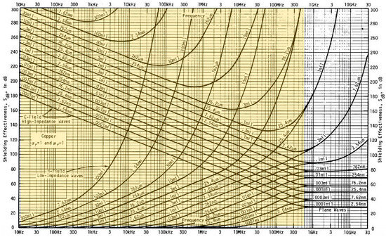
Figure 1.
Example of parametric curves, SEdB = F(f, t), for copper [82].
The first step in establishing the methodology is to confirm the identity between the curves presented above, curves unanimously accepted in the scientific community in the field, in relation to those resulting from analytical calculations for different distances r. The analytical calculations were performed with the Matlab software version R2014b program using Equations (8) and (10)–(12).
The second step consists of establishing the general conception/structure for the employed measurement setup (Figure 2).
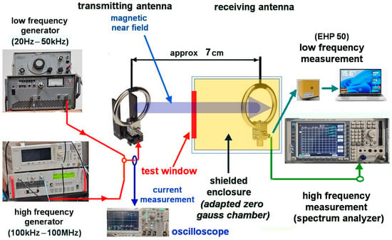
Figure 2.
The general conception/structure for the measurement setup employed for determining SEdB of materials in this work.
Taking into consideration that the reference articles for this work [76,77] use measurement systems that involve materials/shields with relatively large surfaces, which, from the materials makers/providers’ point of view, is an impediment—a shielded measurement enclosure, specifically an adapted Zero-Gauss Chamber, was employed in this work. This conception allows the characterization of conductive materials, with or without magnetic properties, having a disk shape with a diameter of 185 mm. On the other hand, taking into account the extended measurement range (20 Hz–80/100 MHz), two measurement systems were used in this work: the low-frequency measurement system (Figure 3a) and the high-frequency system (Figure 3b). This entails using two generators and two sets of antennas (transmitting and receiving antennas). In order to ensure the identity of the transmitted field in both situations, with and without material between the transmitting and receiving antennas (H0 and H1, respectively), the current in the transmitting antenna was monitored with the help of a current probe and an oscilloscope.
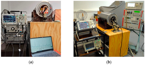
Figure 3.
The two measurement systems used in this work together with the shielded enclosure. (a) Low-frequency measurement system; (b) high-frequency measurement system.
The methodology for determining the shielding effectiveness of materials consists of measuring the magnetic near-field without a shield (H0) and with the shield placed between the transmitting and receiving antennas (H1) and calculating SEdB according to Equation (2).
The shielded enclosure (Figure 4) employed for determining SEdB of materials is cylindrical and has an outer diameter of 300 mm and a length of 500 mm. It is made of three concentric, spaced apart, shields, two made of mu-metal with a thickness of 2 mm and one of soft steel with a thickness of 15 mm. The front closure of the shielded enclosure is made with mu-metal circular rings and a circular ring with a Morse-taper fitting made of soft steel. The front side of the shielded enclosure is provided with a holder that allows fitting the disk-shaped material samples with a diameter of 185 mm and a maximum thickness of 5 mm. On the back side there is a waveguide-type element for passing the cable from the receiving antenna.
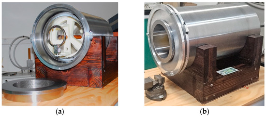
Figure 4.
The magnetically shielded enclosure—adapted Zero-Gauss Chamber. (a) Front view. (b) Side view.
The equipment used for measurements in this work is given in Table 2.

Table 2.
Equipment used for measurements in this work.
The magnetic transmitting and receiving antennas utilized in measurements are presented in Figure 5.
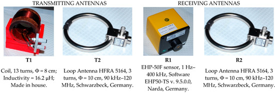
Figure 5.
The magnetic transmitting and receiving antennas used for testing shielding materials.
Except T1, the utilized antennas are perfectly defined by the specifications declared by the manufacturers. The T1 antenna is a coil with an outer diameter of 80 mm and a length of 30 mm, consisting of 13 turns of enameled copper wire with a diameter of 1.9 mm. The low frequency magnetic field emitted by this coil is calculated with the relation [83]:
The magnetic field generated by T1 at 10 cm is approx. 33 µT at a current of 4.5 A.
In order to determine the frequency range where it can be used as a transmitting antenna, T1 was tested with the help of an impedance analyzer at frequencies up to 110 MHz (Figure 6).
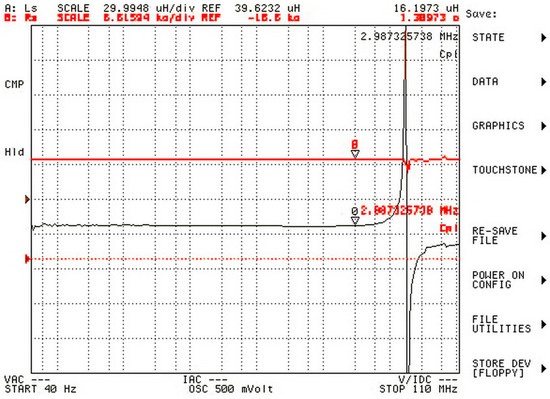
Figure 6.
Inductivity (L) and resistance (R) of T1 antenna with highlighting the resonance frequency.
The T1 antenna has an inductivity of approximately 16.2 µH, and it shows a resonance at 17 MHz, but in this work it was used at frequencies well below its resonant frequency (maximum 300 kHz).
There are 2 important calibrations for the measurement system: determining the dynamic range of the measurement system so that the maximum attenuation of the material under test is below this limit, and the alignment/coaxiality of the antennas (transmission and reception). The latter is simply solved by successive, iterative alignment on the 2 axes, aiming to obtain a maximum of the received field. It is important to mention that perfect alignment of the antennas is not indispensable provided that their relative position is maintained during the measurement of H0 and H1.
The main error sources are:
- -
- antenna misalignment, including their plan-parallelism, which is checked every time according to the above-mentioned procedure;
- -
- ambient magnetic noise (only 50 Hz and its harmonics are detectable), which is eliminated by avoiding 50 Hz, 100 Hz, 150 Hz, 200 Hz, and 300 Hz frequencies, as can be seen in the article;
- -
- current fluctuations in the transmitting antenna, which unfortunately can only be reduced by using high-performance amplifiers or complex electronic systems.
3. Results
3.1. The Dynamic Range of the Shielded Enclosure
First, the dynamic range of the whole measurement system (signal generator, transmitting antenna, shielded enclosure, receiving antenna, and the appropriate measurement instruments) was determined in terms of shielding effectiveness (SEdB). Since the dynamic range of the generators and measurement instruments can be calculated from their datasheets, it follows that the dynamic range of the entire system is determined by the shielding capabilities of the enclosure, which are determined experimentally. This extent was also determined by using Equation (2), where H0 is the magnetic field received inside the shielded enclosure with the front side opened and H1 is the magnetic field received inside the closed shielded enclosure. The shielded enclosure’s front side was closed by using caps made of the same materials that the shielded enclosure is made of (mu-metal and soft steel). The results for two consecutive measurements are given in Table 3, and the dynamic range diagram is given in Figure 7.

Table 3.
Measurement data obtained on testing the dynamic range of the shielded enclosure.
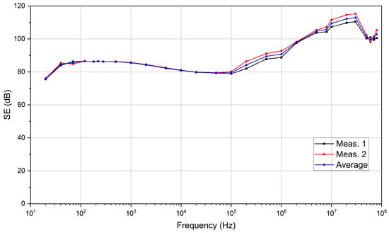
Figure 7.
The dynamic range diagram of the measurement system.
This dynamic range shows the maximum SEdB values that can be determined for the materials tested with the measurement setup shown in Figure 2.
Taking into consideration that the conductive materials with or without magnetic properties used in near-field magnetic shielding applications, with technically accepted thicknesses, have SEdB values starting from a maximum of 60 dB in low frequency, reaching up to 100 dB at high frequency (80 MHz), it is considered that the obtained dynamic range diagram is satisfactory for the purpose of this work.
3.2. Material Testing in the 1 kHz–100 MHz Frequency Range
3.2.1. Copper
In order to validate the method proposed in this article, magnetic shielding effectiveness (SEdB) was determined as a function of frequency for analytically calculable materials (namely isotropic, homogeneous materials with µr ≈ 1 and known conductivity): copper, aluminum, Monel, Toray carbon paper, and graphite. Table 4 shows the experimentally obtained SEdB values for 35 µm thick copper in the frequency range from 1 kHz to 80 MHz, and Figure 8 the corresponding diagram.

Table 4.
Magnetic shielding effectiveness values experimentally obtained for copper 35 µm.
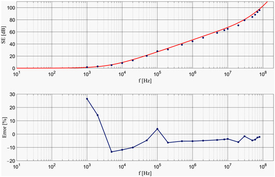
Figure 8.
(Top): Theoretical (solid lines) and experimental (dots) SEdB of copper 35 µm. (Bottom): relative measurement error for copper 35 µm.
Except for the measurements at 20 MHz and 50 MHz, the absolute error was less than 2.5 dB. The relative error values can be seen in the bottom graph in Figure 8; between 50 kHz and 80 MHz the relative error is less than 7%, the average relative error over the same interval being 4.26%. Therefore, it can be stated that the near-field magnetic shielding theory has been experimentally validated for 35 µm thick copper with an error less than 5%.
3.2.2. Conductivity Dependence of SEdB in the Range 100 kHz–80 MHz
To analyze the conductivity dependence of SEdB from an experimental point of view, comparative measurements were made for copper 35 µm (presented above), aluminum 10 µm, Monel 25 µm, and Toray carbon paper 500 µm. The obtained experimental results are presented in Table 5, Table 6 and Table 7 and the corresponding diagrams in Figure 9.

Table 5.
SEdB values experimentally obtained for aluminum 10 µm.

Table 6.
SEdB values experimentally obtained for Monel 25 µm.

Table 7.
SEdB values experimentally obtained for Toray carbon paper 500 µm.
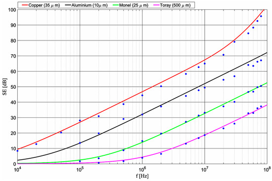
Figure 9.
Theoretical (solid lines) and experimental (blue dots) SEdB curves for copper 35 µm, aluminum 10 µm, Monel 25 µm, and Toray carbon paper 500 µm.
The average relative errors were 4.68% for aluminum, very close to that of copper 35 µm (4.26%), 7.84% for Monel, and 10.7% for Toray carbon paper. The increased error values at low frequencies for Monel (below 500 kHz) and Toray carbon paper (below 2 MHz) are due to the fact that materials with low conductivity have a much lower shielding effectiveness, so that the absolute measurement errors of the system for Monel and Toray carbon paper (less than 2 dB) are reflected as high values of relative error at lower frequencies.
3.2.3. The Dependence of SEdB on the Shield Thickness in the Range 100 kHz–100 MHz
In order to assess the effect of the shield thickness on the shielding effectiveness, high purity graphite foil samples were chosen with thicknesses of 200, 500, and 1000 µm. The experimental data are presented in Table 8, Table 9 and Table 10 and Figure 10.

Table 8.
SEdB values experimentally obtained for 200 µm thick graphite foil.

Table 9.
SEdB values experimentally obtained for 500 µm thick graphite foil.

Table 10.
SEdB values experimentally obtained for 1000 µm thick graphite foil.
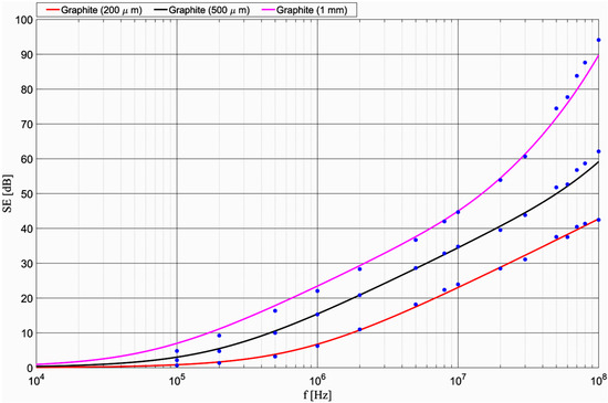
Figure 10.
Calculated (solid lines) and experimental (blue dots) SEdB curves for the 200 µm, 500 µm, and 1000 µm thick graphite foils.
The average relative errors were 6.97% for graphite foil 200 µm, 5.87% for graphite foil 500 µm, and 7.65% for graphite foil 1000 µm.
3.3. Measurements in the Range 20 Hz–300 kHz
In the first stage, the purpose was to make a comparison between the shielding effectiveness values of copper 35 µm (presented above) and copper 200 µm (Table 11) and the corresponding diagrams shown in Figure 11. The average relative error for copper 200 µm over the 280 Hz–300 kHz range was 6.83%.

Table 11.
SEdB values experimentally obtained for 200 µm thick copper.
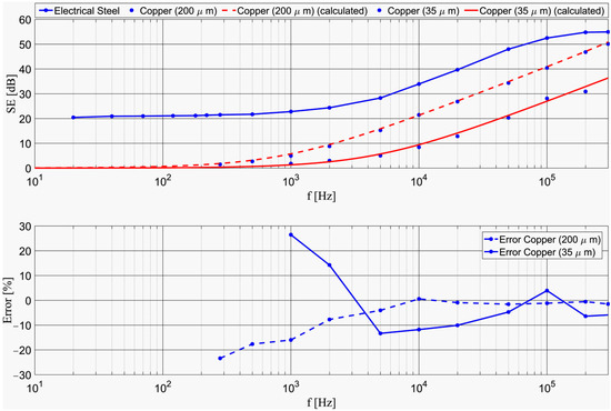
Figure 11.
(Top): SEdB comparison between electrical steel 330 µm, copper 35 µm, and copper 200 µm. (Bottom): Relative measurement errors for copper 35 µm and copper 200 µm.
Considering the results obtained for analytically calculable materials (with well-determined σ and µr ≈ 1), it can be considered that the experimental method presented here validates the theory in the 20 Hz–100 MHz frequency range. Consequently, this experimental method can be used with a sufficiently high degree of confidence for determining SEdB as a function of frequency for analytically calculable materials.
When it comes to materials that cannot be accurately analytically calculated (like multilayers, textiles, and composites), certain variables occur (multiple interfaces, frequency-dependent magnetic permeability, etc.) that are not accounted for in the theoretical model. In this respect, electrical steel with a thickness of 330 µm and σ ≈ 2 · 106 S/m was chosen as an example. The experimental data for electrical steel are given in Table 12, and the corresponding diagram is shown in Figure 11 by comparison with the thin (35 µm) and thick copper (200 µm) samples presented above.

Table 12.
SEdB values experimentally obtained for 330 µm thick electrical steel.
It is observed in Figure 11 that, at very low frequencies, electrical steel shows a higher SEdB than thick copper due to the influence of magnetic permeability, as shown by Equations (1) and (10)–(12).
Next, the effect of overlapping two shielding material samples—electrical steel and thick copper—was experimented on, and the results are presented in Figure 12.
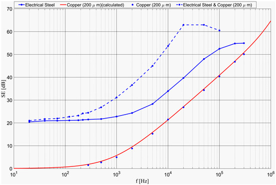
Figure 12.
SEdB of two overlapped samples (electrical steel and thick copper) in comparison with the separate copper 200 µm and electrical steel samples.
This experiment demonstrates that the method described here can also be used to determine the magnetic shielding effectiveness of multilayer structures (e.g., combinations between ferromagnetic materials and materials with high conductivity).
4. Discussion
Analyzing the data and graphs presented in this article, it can be stated that the described experimental setup has succeeded in validating the accepted theory of electromagnetic shielding for conductive materials, with or without magnetic properties, in the frequency range from 20 Hz to 100 MHz. The average relative errors fall mainly within a range of 4.5–7.5%, which, for magnetic field measurements, constitutes a performance in relation to the studied literature. The large errors in the low-frequency area for conductive materials are simply explained by the fact that, when the measured field has small amplitudes, the absolute error is reflected with large values in the relative error.
The frequency dependence of SEdB as well as the dependence of this quantity on the shielding material’s conductivity and thickness have been validated in accordance with the theory shown above. The constructed cell has a good dynamic range, which in the specified frequency range starts from values of approx. 70 dB and exceeds 100 dB at high frequencies.
The fact that analytically incalculable materials could also be tested represents an accomplishment and enables these materials to be characterized with a high degree of confidence from now on.
The main improvements that can be made to the presented measurement system include increasing the power of the high-frequency generator from the current 50 W value to 100 W or even 200 W, which will implicitly lead to an increase in the measurement dynamic range for SEdB and a better accuracy of the readings.
Also, diminishing errors will be possible through a more efficient system for positioning the transmitting antenna relative to the receiving one. This is because the measured amplitude of the magnetic field depends significantly on the parallelism, the coaxiality of the two antennas, and the distance from the transmitting antenna to the shield surface.
In order to demonstrate the applicability of the presented method in the case of analytically incalculable materials, an electrical steel sample was chosen as an example (Figure 12). Once we have demonstrated the agreement between the theoretical predictions and experimental results for conductive materials, it follows that the method can be applied to any type of shield because Equation (2) experimentally defines the shielding effectiveness of any type of material. Thus, each laboratory will be able to perform hundreds of tests on all kinds of materials. However, this research is beyond the scope and purpose of this article.
So, in Figure 12, the SE = F(f) diagrams for Cu, electrical steel, and the two overlapped are presented comparatively. It was found that the placement order of the overlapped shields is not important. This experiment was chosen, only as an example, for the following reasons:
- -
- Electrical steel, like any material with magnetic properties, cannot be analytically calculated because the dependence of magnetic permeability on frequency is not known;
- -
- These materials are of great importance in shielding low-frequency magnetic fields, unlike conductive ones with no magnetic properties, as can be seen in the figure (approx. 20 dB);
- -
- The combination between Cu/Al and magnetic materials is often used in shielding practice, this structure showing superior characteristics compared to the components taken separately, as can be seen from the presented diagrams.
The presented methodology allows comparative studies for different combinations of conductive materials and magnetic materials with the certainty that these tests are valid relative to theory and not as hitherto.
5. Conclusions
This article reports the results obtained during one stage of our ample research activity concerning the experimental validation of the accepted theory regarding the electromagnetic shielding of conductive materials, with or without magnetic properties, in the frequency range 20 Hz–18 GHz.
Until now, this verification has been carried out on narrow frequency ranges and with limitations in terms of measurement dynamic range and material thickness. So far, for electrically thick shields (t >> δ, where δ is the skin depth), the theory has not been confirmed at all. Achieving this objective would have particularly important practical and theoretical implications. As an example, the presented theory (Equations (3) and (4)) shows that a perfectly closed shielded enclosure made of a conductive material, e.g., thin copper (t ≈ 100 µm), shows a radiation attenuation of hundreds of dB at very high frequencies, of the order of tens of GHz, i.e., the electromagnetic field practically does not penetrate the enclosure. This has never been demonstrated experimentally.
This article deals with the 20 Hz–100 MHz frequency range. The most relevant articles in the field directly related to this article are [76,77]. In [76] the authors follow the same algorithm of comparing experimental values with those resulting from applying the theory. Experiments are performed on 770 µm thick copper foils and 20 µm thick aluminum foils with relatively large surfaces (0.04 m2) in the 20 kHz–20 MHz frequency range. The diagrams obtained by them show good agreement with the theoretical predictions, but no analysis of the errors is given. In [77], authors work in an extended frequency range (10 Hz–120 MHz), divided into two subranges (10 Hz–150 kHz and 100 kHz–120 MHz), for materials with measurable conductivity and with large surfaces (approx. 1 m2). No analysis of the errors is given, but large errors are observed in the diagrams at frequencies higher than 80 MHz. Furthermore, the measurements in the two subranges do not match. Moreover, in the second frequency subrange, the measurement dynamic range for the values consistent with the theory is less than 30 dB. For higher values of SEdB, above 30 dB, the results cannot be taken into account.
Hence, the progress made compared to previous research can be summarized as follows:
- the use of much smaller material sizes for measurements than those used until now (~0.027 m2);
- expanded measurement range (between 20 Hz and 100 MHz);
- using a shielded enclosure with a declared dynamic range of 70–105 dB in the specified measurement range.
However, the most important achievement is the fact that by managing to demonstrate the quasi-identity between the values predicted by the theory and those determined experimentally, as a function of both the frequency and the macroscopic parameter σ, as well as a function of the shield thickness, the presented method can be considered validated. Consequently, this method can also be used to determine the electromagnetic shielding effectiveness of materials that are not analytically calculable (composite materials, multilayer materials, or textiles), which are characterized by undefined macroscopic parameters.
From this point of view, this work paves the way for research and experiments that, even if not yet subject to a standard, benefit from an experimentally validated method, which has not happened until now.
Author Contributions
Conceptualization, M.B. and C.M.; methodology, M.B.; software, C.D.; validation, M.B., C.M. and C.D.; resources, C.M.; writing—original draft preparation, M.B. and C.M.; project administration, C.M.; funding acquisition, C.M. All authors have read and agreed to the published version of the manuscript.
Funding
This research was funded by the Romanian Ministry of Research, Innovation and Digitization, CCCDI-UEFISCDI, grant number 42N/2023.
Institutional Review Board Statement
Not applicable.
Informed Consent Statement
Not applicable.
Data Availability Statement
The original contributions presented in the study are included in the article, further inquiries can be directed to the corresponding author.
Conflicts of Interest
The authors declare no conflicts of interest.
References
- Chung, D.D.L. Materials for electromagnetic interference shielding. Mater. Chem. Phys. 2020, 255, 123587. [Google Scholar] [CrossRef]
- Kittur, J.; Desai, B.; Chaudhari, R.; Loharkar, P.K. A comparative study of EMI shielding effectiveness of metals, metal coatings and carbon-based materials. IOP Conf. Ser. Mater. Sci. Eng. 2020, 810, 012019. [Google Scholar] [CrossRef]
- Zimmer, S.; Helwig, M.; Winkler, A.; Modler, N. Modeling Electrical Conductivity of Metal Meshes for Predicting Shielding Effectiveness in Magnetic Fields of Wireless Power Transfer Systems. Electronics 2022, 11, 2156. [Google Scholar] [CrossRef]
- Bachir, G.; Abdechafik, H.; Mecheri, K. Comparison Electromagnetic Shielding Effectiveness Between Single Layer and Multilayer Shields. In Proceedings of the 51st International Universities Power Engineering Conference (UPEC), Coimbra, Portugal, 6–9 September 2016. [Google Scholar] [CrossRef]
- Yang, Q.; Gao, Y.; Li, T.; Ma, L.; Qi, Q.; Yang, T.; Meng, F. Advances in carbon fiber-based electromagnetic shielding materials: Composition, structure, and application. Carbon 2024, 226, 119203. [Google Scholar] [CrossRef]
- Li, J.; Li, J.; Li, T.; Xu, Z.; Chen, Y.; Zhang, L.; Qi, Q.; Liang, B.; Meng, F. Flexible and excellent electromagnetic interference shielding film with porous alternating PVA-derived carbon and graphene layers. iScience 2023, 26, 107975. [Google Scholar] [CrossRef]
- Kumar, R.; Sahoo, S.; Joanni, E.; Singh, R.K.; Tan, W.K.; Kar, K.K.; Matsuda, A. Recent progress on carbon-based composite materials for microwave electromagnetic interference shielding. Carbon 2021, 177, 304–331. [Google Scholar] [CrossRef]
- Li, C.; Zhou, C.; Lv, J.; Liang, B.; Li, R.; Liu, Y.; Hu, J.; Zeng, K.; Yang, G. Bio-molecule adenine building block effectively enhances electromagnetic interference shielding performance of polyimide-derived carbon foam. Carbon 2019, 149, 190–202. [Google Scholar] [CrossRef]
- Deng, W.; Zhi, D.; Li, J.; Li, T.; Liu, Q.; Li, J.; Zhu, J.; Meng, F. Electromagnetic oscillation induced graphene-based aerogel microspheres with dual-chamber achieving high-performance broadband microwave absorption. Compos. B Eng. 2024, 271, 111149. [Google Scholar] [CrossRef]
- Crank, B.; Fricker, B.; Hubbard, A.; Hitawala, H.; Muna, F.I.; Okunlola, O.S.; Doherty, A.; Hulteen, A.; Powers, L.; Purtell, G.; et al. Electromagnetic Radiation Shielding Using Carbon Nanotube and Nanoparticle Composites. Appl. Sci. 2025, 15, 8696. [Google Scholar] [CrossRef]
- Zhao, Q.; Zhang, K.; Zhu, S.; Xu, H.; Cao, D.; Zhao, L.; Zhang, R.; Yin, W. Review on the Electrical Resistance/Conductivity of Carbon Fiber Reinforced Polymer. Appl. Sci. 2019, 9, 2390. [Google Scholar] [CrossRef]
- Voronovich, S.; Paddubskaya, A.; Batrakov, K.; Kuzhir, P.; Maksimenko, S.; Kaplas, T.; Svirko, Y. Electromagnetic Properties of Graphene-like Films in Ka-Band. Appl. Sci. 2014, 4, 255–264. [Google Scholar] [CrossRef]
- Kumari, P.; Tripathi, P.; Singh, S.P.; Kumar, D. Electromagnetic shielding using ceramic materials. In Materials for Potential EMI Shielding Applications, 1st ed.; Joseph, K., Wilson, R., George, G., Eds.; Elsevier: Oxford, UK, 2020; Volume 1, pp. 315–331. [Google Scholar] [CrossRef]
- Kornack, T.W.; Smullin, S.J.; Lee, S.-K.; Romalis, M.V. A low-noise ferrite magnetic shield. Appl. Phys. Lett. 2007, 90, 223501. [Google Scholar] [CrossRef]
- Naito, Y.; Yin, J.; Mizumoto, T. Electromagnetic wave absorbing properties of carbon-rubber doped with ferrite. Electron. Commun. Jpn. (Part II Electron.) 1988, 71, 77–83. [Google Scholar] [CrossRef]
- Kim, D.I.; Takahashi, M.; Anzai, H.; Jun, S.Y. Electromagnetic wave absorber with wide-band frequency characteristics using exponentially tapered ferrite. IEEE Trans. Electromagn. Compat. 1996, 38, 173–177. [Google Scholar] [CrossRef]
- Vinnik, D.A.; Zhivulin, V.E.; Sherstyuk, D.P.; Starikov, A.Y.; Zezyulina, P.A.; Gudkova, S.A.; Zherebtsov, D.A.; Rozanov, K.N.; Trukhanov, S.V.; Astapovich, K.A.; et al. Electromagnetic properties of zinc-nickel ferrites in the frequency range of 0.05–10 GHz. Mater. Today Chem. 2021, 20, 100460. [Google Scholar] [CrossRef]
- Thakur, N.; Sharma, I.; Thakur, P.; Batoo, K.M.; Shirsath, S.E.; Kumar, G. Optimized electromagnetic shielding properties using bismuth-doped barium hexaferrite nanoparticles. Polyhedron 2025, 268, 117384. [Google Scholar] [CrossRef]
- Kruželák, J.; Kvasničáková, A.; Hložeková, K.; Dosoudil, R.; Gořalík, M.; Hudec, I. Electromagnetic Interference Shielding and Physical-Mechanical Characteristics of Rubber Composites Filled with Manganese-Zinc Ferrite and Carbon Black. Polymers 2021, 13, 616. [Google Scholar] [CrossRef]
- Kruželák, J.; Kvasničáková, A.; Džuganová, M.; Hašková, L.; Dosoudil, R.; Hudec, I. Curing, Properties and EMI AbsorptionShielding of Rubber Composites Based on Ferrites and Carbon Fibres. Polymers 2023, 15, 857. [Google Scholar] [CrossRef]
- Wang, M.; Zhang, Y.; Dong, C.; Chen, G.; Guan, H. Preparation and electromagnetic shielding effectiveness of cobalt ferrite nanoparticles/carbon nanotubes composites. Nanomater. Nanotechnol. 2019, 9, 1847980419837821. [Google Scholar] [CrossRef]
- Li, W.; Le, C.; Qiao, L.; Zhen, J.; Ying, Y.; Yu, L.; Jiang, L.; Che, S. Electromagnetic Interference Shielding Effectiveness and Microwave Absorption of Ferrite-polymer Composite Using Ni0.32Cu0.08Zn0.6Fe2O4 Ferrite. In Proceedings of the Progress in Electromagnetic Research Symposium (PIERS), Shanghai, China, 8–11 August 2016. [Google Scholar] [CrossRef]
- Petrović, D.; Lazić, M.; Aleksić, O.; Nikolić, M.V.; Ibrahimović, V.; Pajnić, M. Mn-Zn ferrite line EMI suppressor for power switching noise in the impulse/high current bias regime. Turk. J. Electr. Eng. Comp. Sci. 2018, 26, 2426–2436. [Google Scholar] [CrossRef]
- Wyatt, B.C.; Thakur, A.; Anasori, B. MXenes for atomistic design of 2D nanoceramics. Bull. Am. Ceram. Soc. 2022, 101, 24–28. [Google Scholar]
- Mannafi, A.S.M.; Habib, K.; Ali, S.A.; Younas, M.; Bakthavatchalam, B.; Saha, B.B. MXene-based materials for electromagnetic interference shielding: Fundamentals, mechanisms, and emerging applications. Results Eng. 2025, 27, 107027. [Google Scholar] [CrossRef]
- Ma, H.; Li, C.; Yang, Y.; Fan, Z. 3D Porous MXene Films for Advanced Electromagnetic Interference Shielding and Capacitive Storage. Crystals 2022, 12, 780. [Google Scholar] [CrossRef]
- Xia, X.; Xiao, Q. Electromagnetic Interference Shielding of 2D Transition Metal Carbide (MXene)/Metal Ion Composites. Nanomaterials 2021, 11, 2929. [Google Scholar] [CrossRef]
- Li, Z.; Wang, Z.; Lu, W.; Hou, B. Theoretical Study of Electromagnetic Interference Shielding of 2D MXenes Films. Metals 2018, 8, 652. [Google Scholar] [CrossRef]
- Han, X.; Lee, J.J.; Kyoung, J.S.; Woo, Y.S. The Effect of Microstructural Changes Produced by Heat Treatment on the Electromagnetic Interference Shielding Properties of Ti-Based MXenes. Nanomaterials 2025, 15, 676. [Google Scholar] [CrossRef]
- Gan, Y.; Xiong, Y. Review of MXene synthesis and applications in electromagnetic shielding. RSC Adv. 2025, 15, 9555. [Google Scholar] [CrossRef]
- Allen-Perry, K.; Straka, W.; Keith, D.; Han, S.; Reynolds, L.; Gautam, B.; Autrey, D.E. Tuning the Magnetic Properties of Two-Dimensional MXenes by Chemical Etching. Materials 2021, 14, 694. [Google Scholar] [CrossRef]
- Shukla, V. The tunable electric and magnetic properties of 2D MXenes and their potential applications. Mater. Adv. 2020, 1, 3104. [Google Scholar] [CrossRef]
- Zhang, Y.; Shi, J.; Fu, Z.; Zheng, Q.; Wang, L.; Jiang, W. Engineering metal–organic frameworks for advanced ceramic composites. J. Am. Ceram. Soc. 2025, 105, e20509. [Google Scholar] [CrossRef]
- Amini, M.; Isari, A.; Hashemi, S.A.; Arjmand, M. Metal-organic framework composites for electromagnetic interference shielding. In Applications of Metal-Organic Framework Composites, 1st ed.; Nabipour, H., Rohani, S., Eds.; Elsevier: Amsterdam, The Netherlands, 2025; Volume 1, pp. 251–275. [Google Scholar] [CrossRef]
- Zhang, X.; Qiao, J.; Jiang, Y.; Wang, F.; Tian, X.; Wang, Z.; Wu, L.; Liu, W.; Liu, J. Carbon-Based MOF Derivatives: Emerging Efficient Electromagnetic Wave Absorption Agents. Nano-Micro Lett. 2021, 13, 135. [Google Scholar] [CrossRef] [PubMed]
- Feng, S.; Zhai, F.; Su, H.; Sridhar, D.; Algadi, H.; Xu, B.B.; Pashameah, R.A.; Alzahrani, E.; Abo-Dief, H.M.; Ma, Y.; et al. Progress of metal organic frameworks-based composites in electromagnetic wave absorption. Mater. Today Phys. 2023, 30, 100950. [Google Scholar] [CrossRef]
- Hu, Y.; Sun, G.; Zhang, Q.; Li, M.; Zhu, J.; Shao, G.; Wang, H.; Xu, H.; Lu, H. High-entropy perovskite ceramics with excellent broadband wave-absorbing properties by one-step sintering. Ceram. Int. 2025, 51, 42756–42768. [Google Scholar] [CrossRef]
- Ma, J.; Duan, Y.; Zhu, N.; Jia, H.; Wu, N.; Pang, H. High-entropy perovskite (Y0.2La0.2Sm0.2Nd0.2Gd0.2)CoO3 with dielectric-conductive synergy achieving wide-temperature-range EMI shielding and electromagnetic wave absorption compatibility. Chem. Eng. J. 2025, 520, 165716. [Google Scholar] [CrossRef]
- Katheriya, T.; Pandey, S.; Upadhyay, S. New frontiers in ceramic composites: Tunable electromagnetic interference shielding by realizing negative permittivity in SnO2/LaNiO3 nanocomposites. J. Mater. Chem. C 2025, 13, 13154–13166. [Google Scholar] [CrossRef]
- Liu, Y.; Tuo, P.; Dai, F.-Z.; Yu, Z.; Lai, W.; Ding, Q.; Yan, P.; Gao, J.; Hu, Y.; Hu, Y.; et al. A Highly Deficient Medium-Entropy Perovskite Ceramic for Electromagnetic Interference Shielding under Harsh Environment. Adv. Mater. 2024, 36, 2400059. [Google Scholar] [CrossRef]
- Yuchang, Q.; Qinlong, W.; Fa, L.; Wancheng, Z.; Dongmei, Z. Graphene nanosheets/BaTiO3 ceramics as highly efficient electromagnetic interference shielding materials in the X–band. J. Mater. Chem. C 2016, 4, 371–375. [Google Scholar] [CrossRef]
- Kim, T.; Pak, S.; Lim, J.; Hwang, J.S.; Park, K.H.; Kim, B.S.; Cha, S. Electromagnetic Interference Shielding with 2D Copper Sulfide. ACS Appl. Mater. Interfaces 2022, 14, 13499–13506. [Google Scholar] [CrossRef]
- Wang, Y.; Chen, D.; Yin, X.; Xu, P.; Wu, F.; He, M. Hybrid of MoS2 and Reduced Graphene Oxide: A Lightweight and Broadband Electromagnetic Wave Absorber. ACS Appl. Mater. Interfaces 2015, 7, 26226–26234. [Google Scholar] [CrossRef]
- Prasad, J.; Singh, A.K.; Shah, J.; Kotnala, R.K.; Singh, K. Synthesis of MoS2-reduced graphene oxide/Fe3O4 nanocomposite for enhanced electromagnetic interference shielding effectiveness. Mater. Res. Express 2018, 5, 055028. [Google Scholar] [CrossRef]
- Krause, A.; Nguyen, L.; Tuan, C.; Bonsell, J.; Chen, B. Conductive Concrete as an Electromagnetic Shield. In Proceedings of the IEEE International Symposium on Electromagnetic Compatibility, Pittsburgh, PA, USA, 6–10 August 2012. [Google Scholar] [CrossRef]
- Guan, H.; Liu, S.; Duan, Y.; Cheng, J. Cement based electromagnetic shielding and absorbing building materials. Cem. Concr. Compos. 2006, 28, 468–474. [Google Scholar] [CrossRef]
- Ruscica, G.; Peinetti, F.; Natali Sora, I.; Savi, P. Analysis of Electromagnetic Shielding Properties of Cement-Based Composites with Biochar and PVC as Fillers. C 2024, 10, 21. [Google Scholar] [CrossRef]
- Wang, Y.; Ma, C.; Xie, S.; Wu, Z.; Ji, Z. An ultra-wideband electromagnetic shielding concrete based on multi-scale conductive fillers. Mater. Lett. 2025, 399, 139080. [Google Scholar] [CrossRef]
- Bai, Y.; Xia, Q.; Zhang, D. Mn–Zn ferrite foam concrete: Enhanced electromagnetic wave absorption and pore structure by incorporating carbon fibers. Ceram. Int. 2024, 50, 25578–25597. [Google Scholar] [CrossRef]
- Bheema, R.K.; Gopu, J.; Bhaskaran, K.; Verma, A.; Chavali, M.; Etika, K.C. A review on recent progress in polymer composites for effective electromagnetic interference shielding properties—Structures, process, and sustainability approaches. Nanoscale Adv. 2024, 6, 5773–5802. [Google Scholar] [CrossRef] [PubMed]
- Kausar, A.; Ahmad, I. Conducting Polymer Nanocomposites for Electromagnetic Interference Shielding—Radical Developments. J. Compos. Sci. 2023, 7, 240. [Google Scholar] [CrossRef]
- Shahapurkar, K.; Gelaw, M.; Tirth, V.; Soudagar, M.E.M.; Shahapurkar, P.; Mujtaba, M.A.; Kiran, M.C.; Ahmed, G.M.S. Comprehensive review on polymer composites as electromagnetic interference shielding materials. Polym. Polym. Compos. 2022, 30, 09673911221102127. [Google Scholar] [CrossRef]
- Sathish Kumar, K.; Rengaraj, R.; Venkatakrishnan, G.R.; Chandramohan, A. Polymeric materials for electromagnetic shielding—A review. Mater. Today Proc. 2021, 47, 4925–4928. [Google Scholar] [CrossRef]
- Baltušnikaitė-Guzaitienė, J.; Varnaitė-Žuravliova, S. Textile Based Shielding Materials. In Advanced Materials for Electromagnetic Shielding: Fundamentals, Properties, and Applications, 1st ed.; Jaroszewski, M., Thomas, S., Rane, A.V., Eds.; John Wiley & Sons: Hoboken, NJ, USA, 2019; Volume 1, pp. 219–239. [Google Scholar] [CrossRef]
- Rubežienė, V.; Varnaitė-Žuravliova, S. EMI shielding textile materials. In Materials for Potential EMI Shielding Applications, 1st ed.; Kuruvilla, J., Wilson, R., George, G., Eds.; Elsevier: Oxford, UK, 2020; Volume 1, pp. 357–378. [Google Scholar] [CrossRef]
- Blachowicz, T.; Wójcik, D.; Surma, M.; Magnuski, M.; Ehrmann, G.; Ehrmann, A. Textile Fabrics as Electromagnetic ShieldingMaterials—A Review of Preparation and Performance. Fibers 2023, 11, 29. [Google Scholar] [CrossRef]
- Zecchi, S.; Cristoforo, G.; Bartoli, M.; Tagliaferro, A.; Torsello, D.; Rosso, C.; Boccaccio, M.; Acerra, F. A Comprehensive Review of Electromagnetic Interference Shielding Composite Materials. Micromachines 2024, 15, 187. [Google Scholar] [CrossRef]
- Sankaran, S.; Deshmukha, K.; Ahamed, M.B.; Pasha, S.K.K. Recent advances in electromagnetic interference shielding properties of metal and carbon filler reinforced flexible polymer composites: A review. Compos. Part A 2018, 114, 49–71. [Google Scholar] [CrossRef]
- Rathi, V.; Panwar, V. Electromagnetic Interference Shielding Analysis of Conducting Composites in Near- and Far-Field Region. IEEE Trans. Electromagn. Compat. 2018, 60, 1795–1801. [Google Scholar] [CrossRef]
- Ribadeneyra, M.C. EMI Shielding Composites Based on Magnetic Nanoparticles and Nanocarbons. Ph.D. Thesis, Universidad Carlos III de Madrid, Getafe Madrid, Spain, 11 December 2014. [Google Scholar]
- Wilson, P.F.; Ma, M.T.; Adams, J.W. Techniques for measuring the electromagnetic shielding effectiveness of materials. I. Far-field source simulation. IEEE Trans. Electromagn. Compat. 1988, 30, 239–250. [Google Scholar] [CrossRef]
- ASTM ES7; Test Method for Measuring the Electromagnetic Shielding Effectiveness of Planar Materials. ASTM: West Conshohocken, PA, USA, 1983.
- ASTM D-4935; Standard Test Method for Measuring the Electromagnetic SE of Planar Materials. ASTM: West Conshohocken, PA, USA, 1989.
- Catrysse, J.; De Smedt, R. Some Aspects of Shielding Effectiveness Related to Measurements and Simulations. In Proceedings of the IEEE International Symposium on Electromagnetic Compatibility, Seattle, WA, USA, 2–6 August 1999. [Google Scholar] [CrossRef]
- David, V.; Vremera, E.; Salceanu, A.; Nica, I.; Baltag, O. On the characterization of electromagnetic shielding effectiveness of materials. In Proceedings of the 15th IMEKO TC4 Symposium on Novelties in Electrical Measurements and Instrumentation, Iasi, Romania, 19–21 September 2007. [Google Scholar]
- Amaro, A.; Suarez, A.; Torres, J.; Martinez, P.A.; Herraiz, R.; Alcarria, A.; Benedito, A.; Ruiz, R.; Galvez, P.; Penades, A. Shielding Effectiveness Measurement Method for Planar Nanomaterial Samples Based on CNT Materials up to 18 GHz. Magnetochemistry 2023, 9, 114. [Google Scholar] [CrossRef]
- Catrysse, J.; Pissoort, D.; Vanhee, F. Shielding effectiveness of planar materials: (semi)-standardized measurements from LF to μW. In Proceedings of the ESA Workshop on Aerospace EMC (Aerospace EMC), Valencia, Spain, 23–25 May 2016. [Google Scholar] [CrossRef]
- Yeon, K.; Son, D.; Park, E.B.; Lee, J.Y.; Do, K.H.; Park, J.S. Magnetic Shielding Effectiveness Measurement of Magnetic Steel Sheets in ELF Range. J. Magn. 2008, 13, 173–176. [Google Scholar] [CrossRef]
- Radha, S.M.; Choi, S.H.; Lee, J.H.; Oh, J.H.; Cho, I.-K.; Yoon, I.-J. Ferrite-Loaded Inverted Microstrip Line-Based Artificial Magnetic Conductor for the Magnetic Shielding Applications of a Wireless Power Transfer System. Appl. Sci. 2023, 13, 10523. [Google Scholar] [CrossRef]
- Pavlík, M.; Kolcunová, I.; Medveď, D. Measuring of the shielding effectiveness of electromagnetic field of brick wall in the frequency range from 1 GHz to 9 GHz. In Proceedings of the 2014 15th International Scientific Conference on Electric Power Engineering (EPE), Brno-Bystrc, Czech Republic, 12–14 May 2014. [Google Scholar] [CrossRef]
- Kowal, M.; Kubal, S.; Zielinski, R.J. Measuring the shielding effectiveness of large textile materials in an anechoic chamber. In Proceedings of the International Symposium on Electromagnetic Compatibility—EMC EUROPE, Rome, Italy, 17–21 September 2012. [Google Scholar] [CrossRef]
- IEEE 299-2006; IEEE Standard Method for Measuring the Effectiveness of Electromagnetic Shielding Enclosures. IEEE Electromagnetic Compatibility Society: New York, USA, 2007. [CrossRef]
- Geetha, S.; Kumar, K.K.S.; Rao, C.R.K.; Vijayan, M.; Trivedi, D.C. EMI Shielding: Methods and Materials—A Review. J. Appl. Polym. Sci. 2009, 112, 2073–2086. [Google Scholar] [CrossRef]
- Więckowski, T.W.; Janukiewicz, J.M. Methods for Evaluating the Shielding Effectiveness of Textiles. Fibres Text. East. Eur. 2006, 14, 18–22. Available online: https://www.researchgate.net/journal/Fibres-and-Textiles-in-Eastern-Europe-2300-7354?_tp=eyJjb250ZXh0Ijp7ImZpcnN0UGFnZSI6InB1YmxpY2F0aW9uIiwicGFnZSI6InB1YmxpY2F0aW9uIn19 (accessed on 19 October 2025).
- Bădic, M.; Marinescu, M.-J. The failure of coaxial TEM cells ASTM standards methods in H.F. range. In Proceedings of the IEEE International Symposium on Electromagnetic Compatibility, Minneapolis, MN, USA, 19–23 August 2002. [Google Scholar] [CrossRef]
- Deline, A.; Labrousse, D.; Fabrègue, O.; Vollaire, C.; Grando, J.; André, G. Characterization of Shielding Efficiency for Power Electronics Frequency Domain. J. Electromagn. Anal. Appl. 2012, 4, 85–95. [Google Scholar] [CrossRef]
- Mansour, R.; Benjelloun, N.; Kadi, M. Characterization of the Shielding Effectiveness of Composite Materials Using Electromagnetic Methods Covering a Wide Frequency Range. Prog. Electromagn. Res. M 2023, 118, 117–126. [Google Scholar] [CrossRef]
- Xometry. Available online: https://www.xometry.com/resources/materials/electrical-steel/ (accessed on 24 October 2025).
- Wikipedia. Available online: https://en.wikipedia.org/wiki/Electrical_steel (accessed on 24 October 2025).
- IEEE. Available online: https://www.ieee.li/pdf/viewgraphs/fundamentals_electromagnetic_shield.pdf (accessed on 28 October 2025).
- Schulz, R.B.; Plantz, V.C.; Brush, D.R. Shielding theory and practice. IEEE Trans. Electromagn. Compat. 1988, 30, 187–201. [Google Scholar] [CrossRef]
- White, D.R.J. A Handbook of Electromagnetic Shielding Materials and Performance, 2nd ed.; Don White Consultants: Gainesville, VA, USA, 1980; pp. 1.1–1.40. [Google Scholar]
- Morari, C.; Bădic, M.; Dumitru, C.; Pătroi, E.-A.; Dumitru, G.; Ilie, C.I.; Tănase, N. Characterization of a Mechanical Antenna Based on Rotating Permanent Magnets. Appl. Sci. 2024, 14, 11163. [Google Scholar] [CrossRef]
Disclaimer/Publisher’s Note: The statements, opinions and data contained in all publications are solely those of the individual author(s) and contributor(s) and not of MDPI and/or the editor(s). MDPI and/or the editor(s) disclaim responsibility for any injury to people or property resulting from any ideas, methods, instructions or products referred to in the content. |
© 2025 by the authors. Licensee MDPI, Basel, Switzerland. This article is an open access article distributed under the terms and conditions of the Creative Commons Attribution (CC BY) license (https://creativecommons.org/licenses/by/4.0/).