Abstract
Pressure-preserved coring enables in situ encapsulation of deep coal samples at the borehole bottom. By effectively reducing gas desorption, it supports reliable reserve assessment. Achieving reliable pressure-preserved sealing within the confined space of drilling tools remains a critical technical challenge in the field. Focusing on the pressure controller, this study investigates three key aspects: configuration design, sealing interface behavior, and structural performance. The investigation employs both theoretical modeling and laboratory experiments. First, a geometric configuration design methodology was proposed for the pressure controller using intersecting contact and tapered sealing principles. This was followed by the creation of a spatial motion interference prediction model for the assemblies. Secondly, the contact behavior of intersecting sealing interfaces was studied; analysis of the failure mechanisms showed that the design achieves a pressure-preserved capacity of about 24 MPa. Finally, laboratory tests validated the sealing performance of the pressure controller. The tests confirmed that seal ring failure is characterized by high-pressure extrusion, which is caused by an increased sealing clearance. The research findings elucidate the sealing formation mechanism of the pressure controller, establishing a theoretical foundation for advancing pressure-preserved coring technologies in coalbed methane and gas hydrate exploration and development.
1. Introduction
For a long time, coal has dominated China’s energy consumption structure. In 2024, China’s total energy consumption reached 5.96 billion tonnes of standard coal equivalent, with coal consumption increasing by 1.7% and accounting for 53.2% of the total energy consumption. It is estimated that coal consumption will still represent over 43% of the total when the carbon peak is reached in 2030. Evidently, coal has consistently served as a crucial “ballast” and “stabilizer” in the energy supply chain. As shallow coal resources are depleted, kilometer-deep coal mining is poised to become the norm and mainstay in the future. However, as mining operations extend into greater depths, the nonlinear mechanical behavior of coal and rock masses becomes increasingly pronounced, introducing unprecedented challenges due to the complex and poorly understood conditions of deep geological environments [1,2,3]. The prevention and control of gas-related disasters are of critical importance for ensuring safe coal mine production. In China, mines classified as gassy or prone to gas outbursts account for approximately 33% of the total number of coal mines. Furthermore, the engineering characteristics of deep coal seams, including high stress, high temperature, and high gas pressure, have significantly heightened the potential hazards and challenges associated with managing gas disasters in mines [4,5,6].
The gas content measured by traditional open coring methods is typically lower than the actual reservoir gas content, leading to systematic underestimation [7,8]. In contrast, pressure-preserved coring technology enables in situ sealing and storage of coal samples at the borehole bottom, significantly reducing gas desorption and allowing accurate assessment of gas content in deep coal seams [9,10,11]. The development of a pressure-preserved coring system adapted to the engineering conditions of deep coal mines can provide fundamental geological data for precise gas content determination and geomechanical evaluation. This approach supports the reliable acquisition of critical parameters such as gas distribution, pressure and concentration in deep mining environments and provides a scientific foundation and technical basis for gas disaster prevention and control.
Scholars both domestically and internationally have conducted extensive exploration and research on pressure-preserved coring techniques [12,13,14]. Notably, the impact coring device FPC (Fugro Pressure Corer) and the rotary coring device HYACE Rotary Corer (HRC) are both renowned for their pressure-preserving capabilities of 25 MPa [15,16]. Additionally, the PCB (Pressure Core Barrel) employed in the international deep-sea drilling program can withstand pressure up to 35 MPa [12,13]. The highest pressure-holding capacity is exhibited by the Pressure Core Sampler (PCS) utilized in the International Ocean Drilling Program, capable of withstanding pressure up to 70 MPa [17]. Meanwhile, the GW-CP194-80A pressure-preserved coring tool, developed by China National Petroleum Corporation’s Great Wall Drilling Engineering Co., Ltd., boasts a pressure-holding capacity of up to 60 MPa, and has demonstrated notable application effectiveness [18]. However, the aforementioned coring technologies and equipment are primarily for surface or offshore drilling platforms, which typically offer more spacious operating conditions and fewer design constraints regarding tool dimensions [19,20,21]. Consequently, they are unsuitable for the confined operating environments characteristic of deep coal mine roadways.
Sun Siqing et al. developed a “three-tube single-action” sealed coring device that triggers the closure of a ball valve by creating a pressure differential through ball throwing [22]. With a sealing capacity of 10 MPa and a coring diameter of 38 mm, this device has achieved promising on-site application results. However, the relatively small coring diameter poses a disadvantage for subsequent rock mechanics testing. Wang Fakai et al. proposed a low-temperature freezing coring technique that freezes the coal sample at the bottom of the borehole using a cold source after sampling is completed, thereby achieving the goal of gas storage [23]. The subsequent core extraction process using a coring machine becomes complicated after freezing, and this technique has not yet been widely adopted.
Currently, pressure-preserved coring technology has achieved certain advancements in fields like petroleum development, gas hydrate exploration and geological drilling [24,25,26]. However, deep coal mine drilling coring faces limitations such as narrow operating spaces, low fluid medium displacement, and low circulating pump pressures, rendering some theories and technologies inapplicable. Additionally, due to the weaker strength of coal reservoirs compared to rock layers, the structure of coal bodies is prone to breaking, making coring in coal seams challenging. Therefore, it is imperative to develop a highly integrated pressure-preserved coring system tailored for narrow working spaces in coal mine tunnels; the core technical challenge lies in achieving stable pressure-preserved and sealing within a small space and volume. This study conducts research on core difficulties such as achieving self-triggered pressure-preserved actions and adaptive sealing performance at the bottom of deep coal seams. It proposes design theories and methods for pressure controllers that are suitable for pressure-preserved coring operations in coal mines. Through theoretical modeling, numerical simulations, and laboratory experiments, this study deeply analyzes design principles, sealing mechanisms, and pressure-preserved characteristics, providing theoretical support for the development of technologies and equipment systems for pressure-preserved coring in deep coal seams.
2. Working Principle of Pressure-Preserved Coring
2.1. Structure and Principle of Pressure-Preserved Coring System
The main structure of a deep coal seam pressure-preserved coring system is shown in Figure 1, primarily comprising an elastic clamping mechanism, upper sealing assembly, low-disturbance assembly, and pressure control component. Among these, the pressure control component is key to triggering the pressure-preserved behavior at the borehole bottom. As the core component, the pressure controller is the focus of this research.
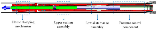
Figure 1.
Main structure of deep coal seam pressure-preserved coring system.
The coring system is lowered into the bottom of the hole along with the drilling tool to carry out the drilling and coring operation. As the drilling process progresses, the core enters the core barrel, and drilling is stopped after completing the predetermined drilling process. Upon activation by the trigger device, the downhole pressure-preserved control component stores the core in its sealed chamber. The sealing valve then closes under initial preload to complete the sealing process. Finally, the drilling tool is lifted to the wellhead, completing the pressure-preserved coring operation, and the pressure-preserved coring system is disassembled as shown in Figure 2.
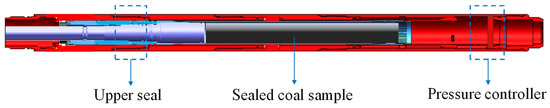
Figure 2.
Schematic diagram for sealing of pressure-preserved coring system.
2.2. Design Requirements for Pressure Controller
High-pressure sealing implementation within confined spaces has been extensively studied in other industries, providing valuable references for the sealing design in this research [27,28,29,30]. Based on the operational principles of the aforementioned coring system, the design of the pressure controller must satisfy the following technical specifications. Firstly, the design must adhere to the self-tightening sealing principle. This requires achieving initial sealing under low preload force while maintaining seal integrity as the internal-external pressure differential increases during coring. Secondly, the design must conform to the assembly constraints within the annular spaces of the coring tool in a narrow borehole. Additionally, it must be capable of performing a flipping motion inside the confined cylindrical space [31,32].
Based on the functional requirements of self-tightening seals and high-pressure sealing structures [33,34,35,36], the conical valve sealing principle is proposed. The sealing valve achieves initial sealing under minimal preload force and exhibits self-sealing capability with increasing pressure.
To meet the constraints of the small assembly space for drilling tools, the installation space and motion principle of the pressure controller have been preliminarily determined, as shown in Figure 3. Initially, the valve seat is located at the base of the pressure-preserved component, while the valve cover is vertically installed within the shell-core barrel annulus. After the coring is completed and the controller is triggered, the valve cover flips within the annular space inside the drilling tool. Upon flipping to a horizontal state, the valve cover contacts the lower seat to form the controller’s initial seal, resulting in a self-energizing interface via the tapered sealing principle.
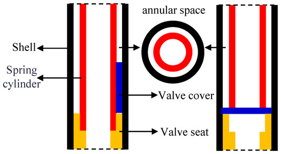
Figure 3.
Assembly and motion diagram of pressure-holding controller.
2.3. Geometric Configuration Design of Pressure Controller
The constrained annular space within the coring tool dictates a departure from the conventional flat-tapered sealing geometry for the valve cover. Furthermore, the design must adopt annular dimensions that conform to the structural parameters of the tool’s lower assembly. The innovative annular valve cover adapts to the assembly space while meeting the boundary conditions of the conical self-tightening seal, resulting in an inverted design perpendicular to the valve seat’s central axis. Combining the spatial geometric characteristics of the intersection line, the configuration design of the pressure controller shown in Figure 4 is completed.
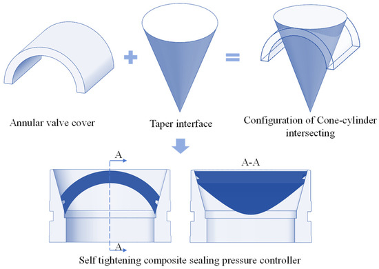
Figure 4.
Design schematic of pressure-preserved controller.
Leveraging the conical self-tightening seal principle and the spatial features of intersection lines, we designed an innovative self-energizing pressure controller, with its sealing mechanism shown in Figure 5. The non-standard sealing interface of the valve cover is processed with a sealing groove to install a rubber O-ring, which can achieve initial sealing under a small spring preload. As pressure on the valve cover rises, the sealing ring is first compressed. The metal sealing interfaces then fully conform, eliminating the sealing gap. This enables the assembly to withstand higher pressure loads while enhancing sealing performance.
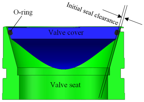
Figure 5.
Sealing principle of pressure controller.
3. Spatial Motion Analysis of the Pressure Controller During Seal Formation
The coring environment in deep coal mines is extremely complex, with small borehole diameters and drilling tool sizes. To ensure a successful pressure-preserved coring process, the pressure controller must exhibit reliable geometric motion. This requires preventing valve cover interference that could jam the corer’s internal components.
3.1. Geometric Model Construction of Sealing Interface Geometric Model Construction
Figure 6 illustrates the schematic diagram of the pressure controller’s sealing interfaces. The valve seat acts as a fixed component with a standard conical sealing surface. In contrast, the valve cover is a moving part whose sealing interface is a complex spatial surface. This surface is generated by the intersection of the valve seat’s cone and the cover’s cylindrical ring, bounded by sophisticated spatial curves. Therefore, constructing a geometric model of the valve cover sealing interface and studying its spatial motion are essential for achieving stable sealing in the pressure controller.
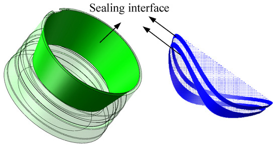
Figure 6.
Sealing interface of pressure controller.
A spatial coordinate system is established as shown in Figure 7. The contact surface of the valve cover of the pressure controller is the intersection area between a ring and a cone. The spatial equation of the contact area can be derived from the spatial geometric equations of the two shapes.
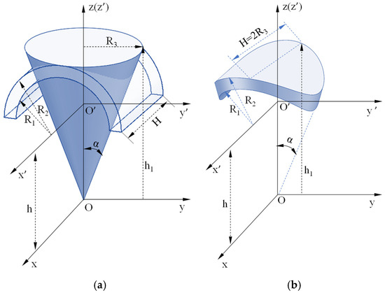
Figure 7.
Geometric configuration diagram of cone and column intersection: (a) Conic and torus surface parameters; (b) Intersecting surface parameters.
In the yOz plane, the conic generatrix equation is: z = ycotα, where α is the angle between the generatrix and the z axis, and the conic surface equation is the surface equation of the generatrix rotating around the z axis.
The conic surface equation is:
where (0 < α < π/2).
The geometric configuration of the valve cover shown in Figure 7 is located in the coordinate system space above the xOy plane, so the conic surface equation is expressed as:
In the O′-x′y′z′ coordinate system, the intersecting area is located in the upper coordinate system of the x′O′y′ plane, where the upper cylindrical surface equation is:
The semi cylindrical surface in the O′-x′y′z′ coordinate system is transformed into the O-xyz coordinate system, and the upper cylindrical surface equation in the o-xyz coordinate system is obtained:
where (), and R1 and R2 are the inner and outer surface radius of the intersecting ring, respectively.
The above conic surface equation is parameterized to obtain the following equation:
The above cylindrical surface equation is parameterized to obtain the following equation:
By combining Equations (1) and (6), the equation of their spatial intersection line is obtained as follows:
When R∈[R1, R2], the above equation represents the contact surface obtained by the intersection of the cone and the ring.
3.2. Spatial Motion Process of Sealing Interface
In actual operation, the valve seat remains stationary while the valve cover rotates on its hinge. This movement brings the two components into full contact, forming an effective seal, and the complete process is illustrated in Figure 8. The essence of its spatial geometric motion is the intersection of a cone and a cylindrical ring, where the intersecting line defines a curved surface that undergoes rotational motion in the spatial coordinate system. This research analyzes the spatial rotation of the curved sealing surface on the valve cover, which is defined by complex intersection lines. The goal is to prevent geometric interference and ensure the controller closes smoothly.
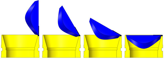
Figure 8.
Closing process of pressure controller.
In the geometric coordinate system, the contact surface of the valve cover is rotated around the hinge axis l of the pressure control valve to achieve a change in geometric position. The hinge axis l is a parallel axis to the y-axis, and the rotation transformation matrix around the y-axis in a three-dimensional coordinate system is:
As shown in Figure 9, the contact surface between the valve cover and the valve seat is translated so that the rotation axis coincides with the y-axis. Then, the valve cover is rotated around the y-axis and the simultaneous equations are solved to determine whether there are intersection points during the rotation process.
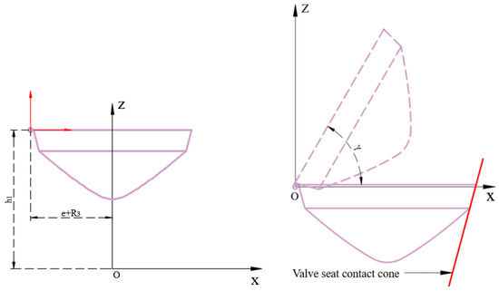
Figure 9.
Schematic diagram of the valve cover flipping in the coordinate system.
From the previous analysis, it can be concluded that the equation of the contact surface in the pressure controller can be expressed as:
We employ homogeneous coordinates to define the spatial transformation of the controller’s contact surface. The initial step involves translating the system until the hinge axis aligns with the y-axis. The transformation equation is:
Then the valve cover is rotated around the y-axis in the negative direction by a specific angle γ to complete the flipping action, and the transformation matrix is as follows:
From the above calculations, the spatial geometric equation of the contact surface during the flipping process can be expressed as follows:
By defining h2 = e + R3, substituting x, y and z from Formula (9) into Equation (12), and combining them with the translated conical contact surface equation of the valve seat, we obtain the equation of the interference region:
By solving this system of equations, it can be determined whether the valve cover interferes with the target contact surface during the flipping process. If interference occurs, the valve cover may become stuck against the valve seat, preventing it from closing properly.
By superimposing the flipped surface and the translated inner shell surface equations, we obtain the interference region equation:
This equation checks for interference between the flipping valve cover and the pressure shell’s inner surface during sealing operations. If interference occurs, it may cause the valve cover to become stuck inside the pressure-preserved shell, resulting in a failure of the coring operation.
In summary, for the parameters of the pressure controller valve cap and valve seat, the following conditions must be met to complete the pressure sealing process: When γ = 0°, the valve cap is in a horizontal position, and at this point, only equation set (13) has a solution; when 0° < γ < 90°, both equation sets (13) and (14) have no solutions; when γ = 90°, the valve cap is in a vertical position, and only equation set (14) has a solution.
This equation can constrain the size parameters of the pressure controller component, ensuring that during the flipping motion of the valve cap in the drilling tool assembly space, it does not interfere with other components.
4. Study on Sealing Mechanism of Pressure Controller
4.1. Finite Element Model Construction
To study the sealing mechanism of the pressure controller, it is necessary to analyze the entire sealing process from pre-tightening to the working state. To understand sealing behavior during pressurization, this study uses finite element analysis to examine how contact characteristics change at the interface, based on the current controller design and sealing principles. Based on operational requirements, the valve seat was fully constrained at its base and circumferential surfaces, while hydraulic loading was applied to the upper surface of the valve cover. In addition, the characteristic dimensions of the structure are provided in Figure 10.
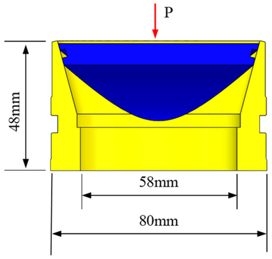
Figure 10.
Schematic diagram of boundary condition constraints for pressure controller.
The initial sealing phase primarily involves the compression process of the O-ring. As extensive research has already been conducted on O-ring compression, this will not be reiterated. This study investigates the contact morphology and load-bearing behavior of sealing interfaces. Specifically, it examines the contact behavior of the sealing interfaces after achieving full contact through O-ring compression, followed by the application of additional high-pressure loads. This analysis aims to reveal the underlying sealing mechanism. Consequently, in the numerical modeling process, the influence of the O-ring is disregarded. Instead, the sealing surfaces are directly defined as contact pairs, and incremental load application is simulated to study the loading process after full contact establishment at the sealing interface.
Considering the corrosion resistance requirements and mechanical performance demands of coal seam drilling operations, Stainless Steel 304 (AISI 304) was selected as the machining material for the pressure controller. Meanwhile, the temperature at the borehole bottom ranges between 30–50 °C due to drilling fluid circulation in the coal mine coring environment. Under these thermal conditions, the impact on the physical and mechanical properties of seal rings and metallic materials is negligible. A finite element model was established as shown in Figure 11 using ABAQUS 2020 software, and the modeling details are shown in Table 1.
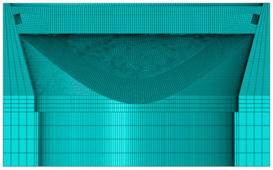
Figure 11.
Finite Element Model of Pressure Controller.

Table 1.
Finite Element Modeling Details.
4.2. Contact Characteristic Analysis
The boundary conditions of the pressure controller’s finite element model were defined, and pressure loads were applied following a pre-tightening then pressurization sequence. The system was gradually pressurized to 30 MPa while analyzing the contact status on the sealing surface.
Figure 12 presents the contact pressure contour plots on the valve seat sealing surface under different pressure conditions, through which the variation patterns of contact zones can be systematically analyzed.
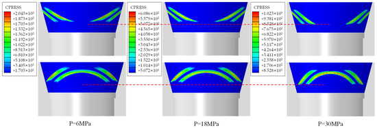
Figure 12.
Contact pressure contour plots of valve seat.
As shown in Figure 12, during the complete hydraulic loading process applied to the valve cover, no continuous uniform sealing zone was observed in the pressure controller. Both sets of sealing contact surfaces exhibited intermittent interruptions at distinct positions. The contact pressure at the sealing interface progressively increased with rising hydraulic load, accompanied by expanding discontinuity regions. These phenomena collectively indicate the absence of necessary conditions for metal-to-metal seal formation under varying hydraulic conditions. Continuous contact is essential for metal-to-metal sealing. The analysis shows that the operating pressure controller cannot achieve this, depending instead on seal ring compression for integrity.
During loading, the contact zone on the valve seat migrated downward as its width expanded. This reveals two mechanical responses: axial displacement due to hydraulic pressure, and bending deformation from structural configuration. These findings demand a systematic investigation into valve cover deformation, supporting the theoretical basis for subsequent structural optimization.
Figure 13 presents the contact pressure contour plots on the valve cover sealing surface corresponding to different pressure conditions. The analysis reveals a consistent correspondence between the contact stress distributions on the valve cover and valve seat surfaces. The observed downward displacement and non-uniform contact patterns result from valve cover bending, demonstrating angular misalignment between the cover and seat.
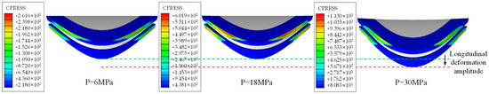
Figure 13.
Contact pressure contour plots of valve cover sealing surfaces.
4.3. Load Bearing Characteristic Analysis
The valve cover’s geometry produces two key effects under hydraulic load: self-sealing behavior and concurrent bending deformation. This dual mechanical response results in significant alterations to the contact morphology at the sealing interface. Consequently, the valve cover’s global load-bearing characteristics require systematic study to assess its sealing performance under hydraulic pressure. Figure 14 shows the von Mises stress distribution on the valve cover surface under different working conditions. The analysis separately examines the high-pressure (loaded) and low-pressure (non-loaded) sides.
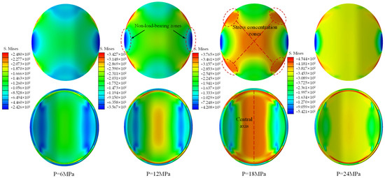
Figure 14.
Contact pressure contour plots of the pressure-bearing surface of the valve cover.
Figure 14 demonstrates the von Mises stress distribution on the valve cover under hydraulic loading. The high-pressure bearing surface (upper face) exhibits progressively increasing stress with notable stress concentration patterns. Four symmetrical stress concentration zones emerge on the sealing surface, particularly pronounced at a hydraulic pressure of 18 MPa, manifesting four-point support characteristics. Conversely, minimal stress levels in lateral non-contact areas define these as non-load-bearing zones, persisting throughout the loading sequence. Eliminating these non-load-bearing regions is therefore essential for achieving metal-to-metal sealing. The valve cover’s cylindrical geometry concentrates the maximum von Mises stress along the inner surface’s central axis during bending. This stress then intensifies and spreads radially as the hydraulic load increases. To systematically investigate deformation characteristics, the central axis region of the lower surface (maximum stress concentration zone) was selected as the evaluation path. Stress distributions and displacement variations under different working conditions were extracted for detailed parametric analysis.
Figure 15 presents the stress variation curves along the central axis path on the lower surface of the valve cover under different operating conditions. The stress peaks at both ends of the curves represent the direct contact regions between the valve cover and valve seat. These regions act as the primary load-bearing zones. The stress peaks at both curve ends correspond to direct contact regions between the valve cover and seat, functioning as primary load-bearing zones. In the central portion, stress follows a characteristic middle-high, edge-low distribution. All stress magnitudes grow progressively with hydraulic load. At 18 MPa, the central stress profile forms a plateau approaching the material’s yield strength. When pressure reaches 24 MPa, central axis stresses show minimal increase, stabilizing near the yield threshold. However, beyond a loading of 24 MPa, a significant escalation in von Mises stress occurs, indicating the initiation of plastic deformation in the central axis vicinity. Thus, 24 MPa hydraulic pressure can be identified as the critical threshold for the onset of plastic deformation in the central axis region of the valve cover lower surface.
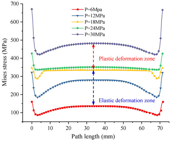
Figure 15.
Stress variation curves along the central axis of the valve cover under different operating conditions.
Figure 16 illustrates the displacement variation curves along the central axis points on the lower surface of the valve cover under different operating conditions. As previously analyzed, the region near the central axis enters the plastic deformation zone when the load exceeds 24 MPa. Therefore, displacement variation curves at 27 MPa and 28.5 MPa loads are included for comparative analysis. The maximum displacement along the entire central axis occurs in the middle region, with a significant increase in displacement increment observed when the load surpasses 24 MPa, as shown in Table 2. The valve cover exhibits an overall concave deformation pattern, while the contact regions at both sealing surfaces provide supporting constraints, resulting in relatively smaller displacement variations.
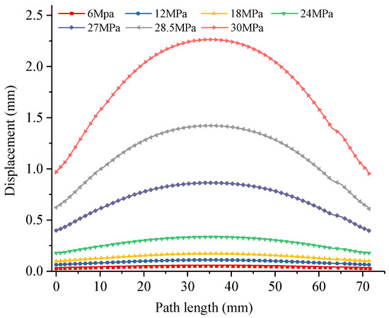
Figure 16.
Displacement variation curves along the central axis of the valve cover under different operating conditions.
Table 2.
Maximum displacement variation along the central axis of the valve.
In summary, the sealing capability of the pressure controller during hydraulic loading primarily relies on the rubber O-ring, without achieving the intended transition to metal-to-metal sealing. Consequently, the design objective of composite sealing remains unfulfilled. Under the current configuration and material parameters, the maximum hydraulic pressure capacity of the valve cover is 24 MPa. Exceeding this pressure will result in rapid progression to plastic deformation and subsequent sealing failure; this finding will be verified through subsequent laboratory tests. Nevertheless, this sealing capacity fully satisfies the engineering requirements for pressure-preserved coring in deep coal mining operations.
5. Laboratory Testing and Experimentation
5.1. Experimental Plan
Experimental Objectives: (1) To evaluate the sealing capacity of the pressure controller through hydraulic loading tests and (2) to analyze the sealing contact characteristics by conducting morphological examination of the sealing interface after hydraulic loading. The complete test system comprises an external hydraulic testing platform and a high-pressure test chamber assembly [32]. As illustrated in Figure 17, the high-pressure test chamber assembly includes the following components: high-pressure cavity, high-pressure fluid inlet, preload spring, pressure controller, and lower fixed end cap. The pressure controller is installed within the high-pressure chamber body. The preload spring is compressed to provide the initial sealing force required for the pressure controller, while the lower fixed end cap secures the controller within the chamber. As shown in Figure 18, the high-pressure test chamber is connected to the hydraulic testing platform. Hydraulic fluid is injected into the chamber through the high-pressure inlet, with pressure incrementally increased to validate the sealing capability of the pressure controller.
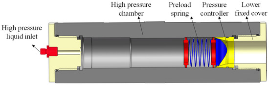
Figure 17.
Drawing of assembly of high-pressure test chamber components.
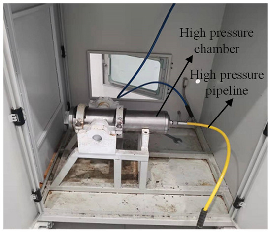
Figure 18.
Hydraulic test system diagram.
Figure 19 displays the physical prototype of the pressure controller manufactured using the aforementioned design methodology. Following the prescribed experimental procedure, the pressure controller assembly was installed into the high-pressure chamber body. The system was subsequently connected to a hydraulic power unit, and pressure was incrementally applied through a stepwise pressurization process.
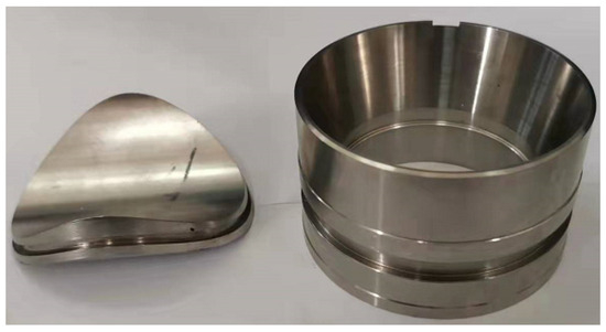
Figure 19.
Material object of pressure controller.
5.2. Result Analysis
Figure 20 presents the hydraulic loading curve recorded during the experimental procedure. During the initial stage of stepwise pressurization to 5 MPa, a pressure drop phenomenon was observed due to either minor misalignment between the valve cover and valve seat, or minimal leakage from the sealing ring. Upon reaching approximately 24 MPa, a pressure drop was observed followed by pressure stabilization failure, indicating significant leakage occurrence that necessitated test termination. The observed leakage pressure is closely aligned with the maximum sealing capacity of the pressure controller as defined through numerical simulation, which validates the effectiveness of both the simulation methodology and experimental testing approach.
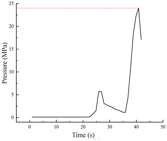
Figure 20.
Test pressure curve.
Post-test disassembly of the pressure controller enabled detailed analysis of surface contact morphology on both the valve cover and valve seat sealing interfaces. Figure 21 displays the contact imprint pattern on the valve seat sealing interface of the pressure controller after testing. The analysis reveals the absence of continuous metal contact imprints on the valve seat surface, which aligns with the numerical simulation results presented earlier. Discontinuity points are observed at symmetrical positions across both sealing interfaces, confirming that metal-to-metal sealing was not achieved under the preload force applied during initial sealing formation. Furthermore, scratch marks with varying degrees of severity are identified between the two sealing zones, demonstrating relative sliding occurred between the valve cover and valve seat sealing interfaces during hydraulic loading.
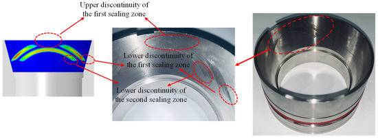
Figure 21.
Sealing interface morphology of pressure controller.
The current pressure-preserved capacity primarily originates from the initial sealing formed by the compressed O-ring seal. Although metal-to-metal sealing was not achieved, the system maintains a sealing integrity above 20 MPa. This capability enables its use in lower-pressure applications such as coal mine gas and gas hydrate pressure-retained coring. Concurrently, systematic analysis of the O-ring failure modes is required to improve sealing stability.
Figure 22 illustrates the extrusion failure zones of the seal ring, which are predominantly located at the lower boundaries of the lower sealing contact regions. This phenomenon occurs due to significant bending deformation of the valve cover under high hydraulic loading, resulting in disengagement of the metal sealing surfaces and subsequent enlargement of the sealing gap. When this deformation exceeds the design limits of the seal, extrusion failure of the O-ring is observed. This deformation mechanism is fully consistent with the simulation process illustrated in Figure 23.
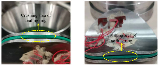
Figure 22.
Valve cover rubber sealing ring crushing area.
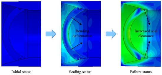
Figure 23.
Evolution of the sealing interface in the pressure controller.
Figure 24 presents a 12-times magnified view of the extrusion failure zone in the rubber seal ring. The image reveals severe surface roughening and fragmentation within a defined width region, which is characteristic of a typical O-ring extrusion failure mode.
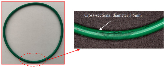
Figure 24.
Enlarged view of rubber seal ring crushed part.
Numerical simulations and laboratory experiments demonstrate that the pressure controller achieves self-energized sealing functionality. However, it fails to complete a stable transition from elastomeric to metal-to-metal sealing despite increasing the preload. The underlying cause lies in the relative sliding and discontinuous load-bearing behavior of the metal sealing interface during internal hydraulic pressure escalation, which consequently induces localized metal sealing failure zones. Thus, to extend this sealing design theory of the pressure controller to high-temperature, high-pressure (HTHP) environments, further investigation into this phenomenon and corresponding structural optimization are imperative.
6. Conclusions
(1) This paper presents a design methodology for pressure controllers adapted to pressure-preserved coring operations in deep coal mines. Based on intersecting contact and tapered sealing principles, we developed an innovative configuration with self-adaptive sealing capability. Spatial geometric equations for the sealing interface were derived from the controller’s operational principles and kinematic characteristics. Additionally, spatial kinematic analysis yielded a predictive model for motion interference, addressing potential assembly constraints.
(2) Numerical simulations of the intersecting sealing interfaces revealed discontinuous contact patterns. This shows the sealing mechanism depends mainly on O-ring compression. Load-bearing capacity evaluation confirms that the pressure controller maintains a hydraulic pressure-preserved capacity of approximately 24 MPa.
(3) A dedicated sealing test system was designed in accordance with the operational principles of the pressure controller to evaluate its sealing performance. Hydraulic tests conducted using this system indicated leakage initiation at 23.5 MPa, a result closely aligned with simulation predictions. Further analysis of seal ring failure mechanisms identified high-pressure extrusion as the dominant failure mode, attributed to excessive sealing clearance.
(4) The pressure controller investigated in this study demonstrates a sealing capacity that significantly surpasses the requirements for pressure-preserved coring in deep coal mines. The technology shows promise for coalbed methane and gas hydrate applications, though metal-to-metal sealing requires further development for extreme temperature and pressure conditions.
Author Contributions
J.L. (Jianan Li): Conceptualization, Data curation, Funding acquisition, Investigation, Writing—original draft. C.L.: Software, Supervision, Validation. L.Z.: Methodology, Project administration, Writing—review and editing. J.L. (Ju Li): Formal analysis, Software, Visualization. Z.Y.: Investigation, Validation, Visualization. Z.Z.: Methodology. All authors have read and agreed to the published version of the manuscript.
Funding
The authors are grateful for the financial support from the Deep Earth Probe and Mineral Resources Exploration-National Science and Technology Major Project (2024ZD1003901), the National Natural Science Foundation of China (No. 42477190), the Guangdong Provincial Key Laboratory of Deep Earth Sciences and Geothermal Energy Exploitation and Utilization (No. DESGEEU-2023-6), and Sichuan Provincial Special Financial Support for Postdoctoral Research Projects (No. TB2025006).
Institutional Review Board Statement
Not applicable.
Informed Consent Statement
Not applicable.
Data Availability Statement
The raw data supporting the conclusions of this article will be made available by the authors on request.
Conflicts of Interest
All authors declare that they have no known competing financial interest or personal relationships that could have appeared to influence the work reported in this paper.
References
- Xie, H.; Lu, J.; Li, C.; Li, M.; Gao, M. Experimental study on the mechanical and failure behaviors of deep rock subjected to true triaxial stress: A review. Int. J. Min. Sci. Technol. 2022, 23, 915–950. [Google Scholar] [CrossRef]
- Zhou, H.; Lu, M.; Xie, H.; Jia, W.; Peng, R.; Wang, Y.; Chen, B.; Jing, P. Numerical analysis on mechanical difference of sandstone under in-situ stress, pore pressure preserved environment at depth. Int. J. Min. Sci. Technol. 2023, 33, 1339–1350. [Google Scholar] [CrossRef]
- Xie, H. Research review of the state key research development program of China: Deep rock mechanics and mining theory. J. China Coal Soc. 2019, 44, 1283–1305. (In Chinese) [Google Scholar] [CrossRef]
- Akdaş, S.B.; Fişne, A. A data-driven approach for the prediction of coal seam gas content using machine learning techniques. Appl. Energy 2023, 347, 121499. [Google Scholar] [CrossRef]
- Ruiyue, Y.; Chunyang, H.; Zhongwei, H.; Xianzhi, S.; Haitao, W. Coal breakage using abrasive liquid nitrogen jet and its implications for coalbed methane recovery. Appl. Energy 2019, 253, 113485. [Google Scholar] [CrossRef]
- Abhijit, M.; Satya, H.; Shimin, L. Laboratory measurement and modeling of coal permeability with continued methane production: Part 1—Laboratory results. Fuel 2012, 94, 110–116. [Google Scholar] [CrossRef]
- Wang, Y.; Kang, J.; Zhou, F. Evaluation of lost gas in the borehole drilling stage: Implication for the direct method of coalbed methane content determination. J. Nat. Gas Sci. Eng. 2022, 105, 104711. [Google Scholar] [CrossRef]
- Li, J.; Lu, S.; Zhang, P.; Cai, J.; Li, W.; Wang, S.; Feng, W. Estimation of gas-in-place content in coal and shale reservoirs: A process analysis method and its preliminary application. Fuel 2020, 259, 116266. [Google Scholar] [CrossRef]
- Li, J.; Xie, H.; Li, J.; Wang, T.; Liu, G.; Gao, M.; Zhang, Z. A lightweight pressure- and gas-preserved coring tool for accurate gas content measurement in deep coal seams. J. Clean. Prod. 2025, 501, 145230. [Google Scholar] [CrossRef]
- Li, J.; Li, J.; Wang, T.; Shi, X.; Cui, P.; Shang, D. Development and validation of a remotely triggered pressureand gas-preserved coring tool for deep coal mines in drilling fluid environments. Adv. Geo-Energy Res. 2024, 14, 147–160. [Google Scholar] [CrossRef]
- Zhao, S.; Lu, S.; Wu, J.; Li, W.; Liu, Y.; Li, J.; Zhang, J.; Xia, Z.; Huang, S. Comparison and Verification of Gas-Bearing Parameter Evaluation Methods for Deep Shale Based on the Pressure Coring Technique. Energy Fuels 2023, 37, 2066–2077. [Google Scholar] [CrossRef]
- Fulthorpe, C.S.; Miller, K.G.; Droxler, A.W.; Hesselbo, S.P.; Camoin, G.F.; Kominz, M.A. Drilling to Decipher Long-Term Sea-Level Changes and Effects A Joint Consortium for Ocean Leadership, ICDP, IODP, DOSECC, and Chevron Workshop. Sci. Drill. 2008, 6, 19–28. [Google Scholar] [CrossRef]
- He, S.; Peng, Y.; Jin, Y.; Wan, B.; Liu, G. Review and Analysis of Key Techniques in Marine Sediment Sampling. Chin. J. Mech. Eng. 2020, 33, 160–176. [Google Scholar] [CrossRef]
- Pape, T.; Hohnberg, H.J.; Wunsch, D.; Anders, E.; Freudenthal, T.; Huhn, K.; Bohrmann, G. Design and deployment of autoclave pressure vessels for the portable deep-sea drill rig MeBo (Meeresboden-Bohrgert). Sci. Drill. 2017, 23, 29–37. [Google Scholar] [CrossRef]
- Schultheiss, P.J.; Francis, T.J.G.; Holland, M.; Roberts, J.A.; Amann, H.; Parkes, R.J.; Martin, D.; Rothfuss, M.; Tyunder, F.; Jackson, P.D. Pressure coring, logging and subsampling with the HYACINTH system. Geol. Soc. Lond. Spec. Publ. 2006, 267, 151–163. [Google Scholar] [CrossRef]
- Schultheiss, P.; Holland, M.; Humphrey, G. Wireline Coring and Analysis under Pressure: Recent Use and Future Developments of the HYACINTH System. Sci. Drill. 2009, 7, 44–50. [Google Scholar] [CrossRef]
- Abid, K.; Spagnoli, G.; Teodoriu, C.; Falcone, G. Review of pressure coring systems for offshore gas hydrates research. Underw. Technol. 2015, 33, 19–30. [Google Scholar] [CrossRef]
- Yang, L.; Su, Y.; Luo, J.; Sun, S. Development and application of GW−CP194−80A pressure−maintaining coring tool. Nat. Gas Ind. 2020, 40, 91–96. (In Chinese) [Google Scholar] [CrossRef]
- Guo, D.; Xie, H.; Gao, M.; Li, J.; He, Z.; Chen, L.; Li, C.; Zhao, L.; Wang, D.; Zhang, Y.; et al. In-situ pressure-preserved coring for deep oil and gas exploration: Design scheme for a coring tool and research on the in-situ pressure-preserving mechanism. Energy 2024, 286, 129519. [Google Scholar] [CrossRef]
- You, K.; Thomas, C.; Savage, A.; Cardona, A.; Flemings, P.; Murphy, Z.; O’Connell, J. Dissolved Methane Diffusion Drives Hydrate-Bearing Pressure Core Degradationduring Long-Term Storagein Water. Energy Fuels 2024, 38, 10879–10889. [Google Scholar] [CrossRef]
- Sahu, C.; Kumar, R.; Sangwai, J.S. Comprehensive Review on Exploration and Drilling Techniques for Natural Gas Hydrate Reservoirs. Energy Fuels 2020, 34, 11813–11839. [Google Scholar] [CrossRef]
- Sun, S.; Zhang, Q.; Zheng, K.; Long, W. Technology and equipment of sealed coring for accurate determination of coalbed gas content in ground well. J. China Coal Soc. 2020, 45, 2523–2530. (In Chinese) [Google Scholar] [CrossRef]
- Wang, F.; Luo, Y.; Liang, Y.; Peng, J.; Li, B. Sampling Methane-Bearing Coal Seams by Freezing Method: Coalbed Methane Desorption and Inhibition Characteristics Under Freezing Temperature. Nat. Resour. Res. 2020, 29, 1351–1360. [Google Scholar] [CrossRef]
- Xie, H.; Liu, T.; Gao, M.; Chen, L.; Zhou, H.; Ju, Y.; Gao, F.; Peng, X.; Li, X.; Peng, R.; et al. Research on in-situ condition preserved coring and testing systems. Pet. Sci. 2021, 18, 1840–1859. [Google Scholar] [CrossRef]
- Huang, W.; Li, J.; Liu, Z.; Yang, M.; You, Z.; Xie, H. Study of a low-disturbance pressure-preserving corer and its coring performance in deep coal mining conditions. Int. J. Min. Sci. Technol. 2023, 33, 1397–1410. [Google Scholar] [CrossRef]
- Li, X.; Zhang, X.; Ma, Y.; Tian, Y.; Han, Z.; Zhang, Y. Design and Experimental Study of an Improved Pressure Core Sampler for Marine Gas Hydrates. ACS Omega 2024, 9, 14977–14984. [Google Scholar] [CrossRef]
- Aljuboury, M.; Rizvi, J.; Grove, S.; Cullen, R. A numerical investigation of the sealing performance and the strength of a raised face metallic bolted flange joint. Int. J. Press. Vessel. Pip. 2020, 189, 104255. [Google Scholar] [CrossRef]
- Murtagian, G.R.; Fanelli, V.; Villasante, J.A.; Johnson, D.H.; Ernst, H.A. Sealability of Stationary Metal-to-Metal Seals. J. Tribol. 2004, 126, 591–596. [Google Scholar] [CrossRef]
- Haruyama, S.; Nurhadiyanto, D.; Choiron, M.A.; Kaminishi, K. Influence of surface roughness on leakage of new metal gasket. Int. J. Press. Vessel. Pip. 2013, 111, 146–154. [Google Scholar] [CrossRef]
- Teles, D.B.; Gouveia, S.M.; Clarke, T.G.R. Identification of leakage in ball valves by analysis of pressure and torque signatures in cyclical tests under critical operating conditions. Eng. Fail. Anal. 2020, 117, 104828. [Google Scholar] [CrossRef]
- Li, J.; Wang, J.; Hu, Y.; You, Z.; Xu, M.; Wang, Y.; Zou, Z.; Kang, Q. Contact performance analysis of pressure controller’s sealing interface in deep in-situ pressure-preserved coring system. Pet. Sci. 2022, 19, 1334–1346. [Google Scholar] [CrossRef]
- Li, C.; Xie, H.; Gao, M.; Chen, L.; Zhao, L.; Li, C.; Wu, N.; He, Z.; Li, J. Novel designs of pressure controllers to enhance the upper pressure limit for gas-hydrate-bearing sediment sampling. Energy 2021, 227, 120405. [Google Scholar] [CrossRef]
- Garfield, G.; Mackenzie, G. Zonal Isolation Applications Utilizing New Metal-To-Metal Sealing Technology Demonstrates Potential For Offshore And Deepwater Environments. In Proceedings of the Offshore Mediterranean Conference and Exhibition, Ravenna, Italy, 28 March 2007; p. OMC-2007-163. Available online: https://onepetro.org/OMCONF/proceedings-pdf/OMC07/OMC07/OMC-2007-163/1833024/omc-2007-163.pdf (accessed on 14 November 2025).
- Dong, X.; Zhou, F.; Jiang, W.; Xie, Y.; Zhang, Y.; Xie, X.; Zhai, X.; Lu, C.; Li, G.; Jiang, X. Failure analysis of the conical gaskets in ultra-high pressure pipeline sealing devices: Experiment and numerical simulation. Eng. Fail. Anal. 2022, 133, 105946. [Google Scholar] [CrossRef]
- Inose, K.; Sugino, M.; Sugimura, J. Fundamental Evaluation of Sealability of Greased Metal-to-Metal Seal on Premium Threaded Joints at High Pressure and High Temperature. Tribol. Online 2021, 16, 192–198. [Google Scholar] [CrossRef]
- Timelli, G.; Mori, A.D.; Haghayeghi, R. Reliability of a high-pressure die cast Al alloy radiator. Eng. Fail. Anal. 2019, 105, 87–97. [Google Scholar] [CrossRef]
Disclaimer/Publisher’s Note: The statements, opinions and data contained in all publications are solely those of the individual author(s) and contributor(s) and not of MDPI and/or the editor(s). MDPI and/or the editor(s) disclaim responsibility for any injury to people or property resulting from any ideas, methods, instructions or products referred to in the content. |
© 2025 by the authors. Licensee MDPI, Basel, Switzerland. This article is an open access article distributed under the terms and conditions of the Creative Commons Attribution (CC BY) license (https://creativecommons.org/licenses/by/4.0/).