Abstract
Strain localization is a critical phenomenon in geotechnical materials, serving as a precursor to the failure of engineering structures such as slopes, foundations, and tunnels. This paper presents a comprehensive review of the theoretical, experimental, and numerical advances in the study of strain localization. Theoretically, the review spans from classical empirical criteria for shear band inclination to the more rigorous bifurcation theory, which mathematically defines the onset of localization as a loss of uniqueness in the governing equations. Experimentally, various laboratory techniques including direct shear, triaxial, plane strain, and true triaxial tests are discussed, highlighting how they have revealed the influences of microstructure, stress path, and boundary conditions on shear band development. The core of the review focuses on numerical simulations, critically analyzing the limitations of the classical Finite Element Method (FEM) due to mesh dependency. It then elaborates on advanced regularization strategies, encompassing weak discontinuity methods (e.g., Cosserat continuum theory) that introduce an internal length scale to model finite-width shear bands, and strong discontinuity methods (e.g., the Strong Discontinuity Approach, SDA) for simulating discrete cracks. Significant emphasis is placed on innovative coupled approaches, particularly the Cos-SDA model, which integrates the advantages of both weak and strong discontinuity methods to seamlessly simulate the entire progressive failure process from diffuse localization to discrete slip. Furthermore, the application of spectral analysis for evaluating the regularization performance of these numerical methods is examined. Finally, the review concludes by identifying persistent challenges and outlining promising future research directions, including 3D modeling, multi-field coupling, and the integration of data-driven techniques. This synthesis aims to provide a valuable reference for advancing the prediction and management of failure in geotechnical structures.
1. Introduction
When geotechnical materials are subjected to external loads, deformation initially occurs locally. As the load continues to act, local deformation and damage become relatively concentrated, forming specific regions that ultimately lead to material instability and failure. This class of phenomena is collectively referred to as “strain localization.” This definition typically encompasses phenomena such as slip lines in metals, shear bands in soils, and cracks in quasi-brittle materials. Depending on the type of load, strain localization can be categorized into shear strain localization and tensile strain localization. For geotechnical materials, strain localization generally manifests in the form of shear bands. Therefore, strain localization in geotechnical materials is often termed “shear localization.” This phenomenon adversely affects the structural integrity and often serves as a direct precursor to structural failure. Consequently, accurately predicting the initiation, propagation, and formation of shear bands is crucial for correctly assessing the safety of geotechnical structures.
It is important to note that the modeling of strain localization in soils faces additional challenges due to the diverse behaviors exhibited by different soil types. For instance, normally consolidated clays typically exhibit contractive behavior and may develop diffuse shear bands under undrained conditions, whereas over-consolidated clays tend to dilate and form more localized, persistent shear bands. These differences in mechanical response, influenced by factors such as stress history, density, and fabric anisotropy, must be carefully considered in the development of constitutive models and numerical simulations to ensure accurate predictions across a wide range of geotechnical materials and conditions.
The localized deformation and failure of geotechnical materials is a process that gradually transitions from continuous deformation to discontinuous deformation. Generally, this process can be divided into three stages [1,2,3]:
- (a)
- Continuum stage (where displacement and strain fields are continuous): During the initial loading or deformation stage, when external forces are applied to geotechnical materials, strain within the material gradually develops as the external forces increase. However, the relative displacement between different parts of the material remains small, and deformation continues to exhibit continuous characteristics. This stage typically manifests as linear elastic or nonlinear elastoplastic behavior.
- (b)
- Weak discontinuity stage (where the displacement field is continuous, but the strain field is discontinuous): As external forces increase or loading continues, localized failure or strain concentration becomes evident in the mechanical response of the geotechnical material. This is usually caused by the deterioration of the material’s internal microstructure or displacement instability. During this stage, strain begins to exhibit discontinuities, such as the formation and development of shear bands. Such strain discontinuities can lead to stress redistribution and a reduction in local load-bearing capacity.
- (c)
- Strong discontinuity stage (where both displacement and strain fields are discontinuous): When external forces or strains continue to increase, shear bands and slip surfaces within the geotechnical material further propagate, ultimately leading to discontinuous displacement across the entire material. This stage is typically characterized by the formation of distinct failure zones or faults, accompanied by significant displacements and unstable behavior. The discontinuous displacement stage is commonly observed in geohazards (such as landslides and collapses) or during the failure processes of engineering structures.
The transition from a continuous phase to strain discontinuity, and finally to displacement discontinuity, reflects the continuous–discontinuous deformation characteristics and mechanical responses of geotechnical materials under external forces. Understanding and studying this process is crucial for engineering design and the prevention and control of geological hazards. It holds significant theoretical and practical importance for ensuring the safety and stability of engineering structures and for the prevention and management of geological disasters. For different types of geotechnical materials, the evolution of strain localization bands typically follows two distinct modes.
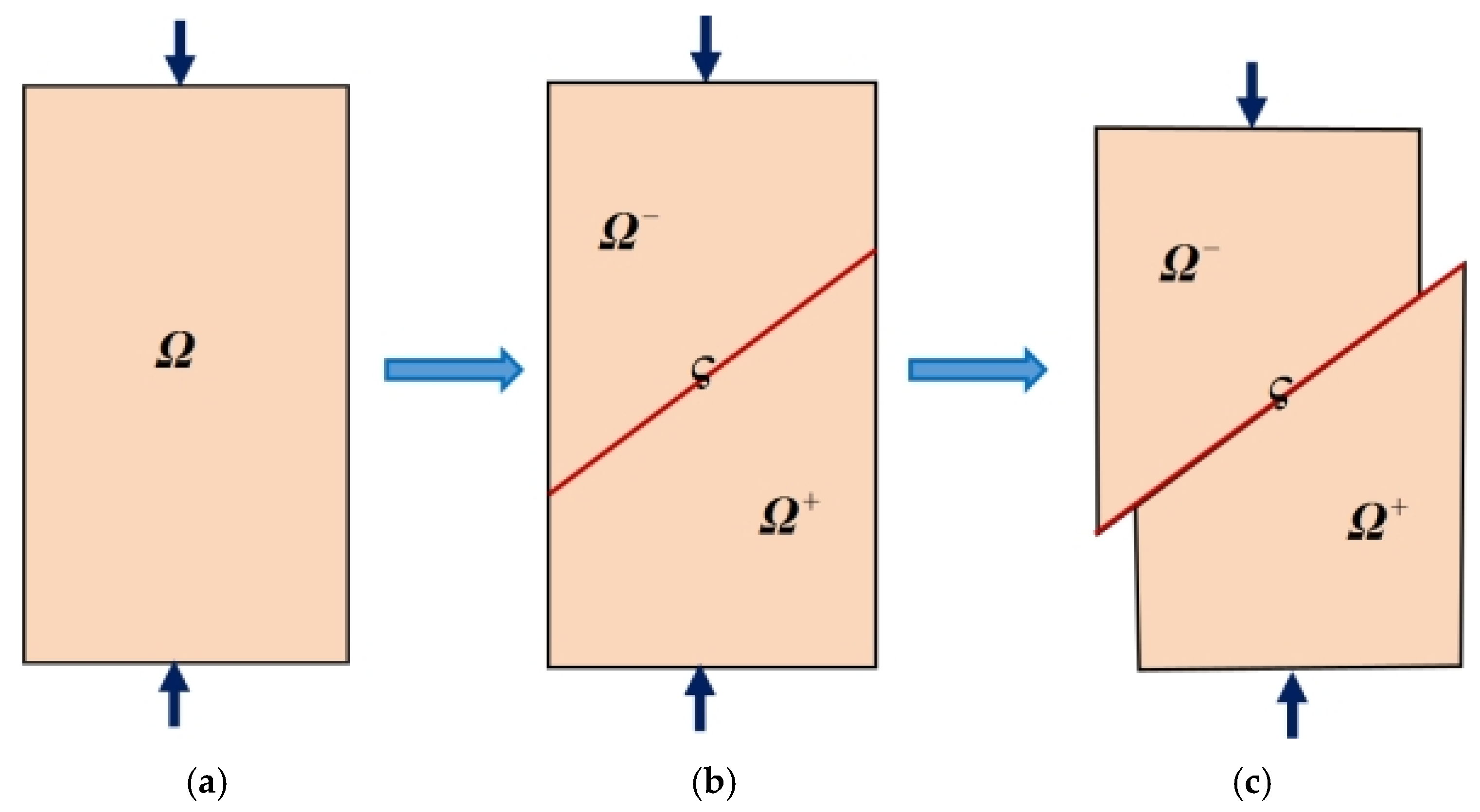
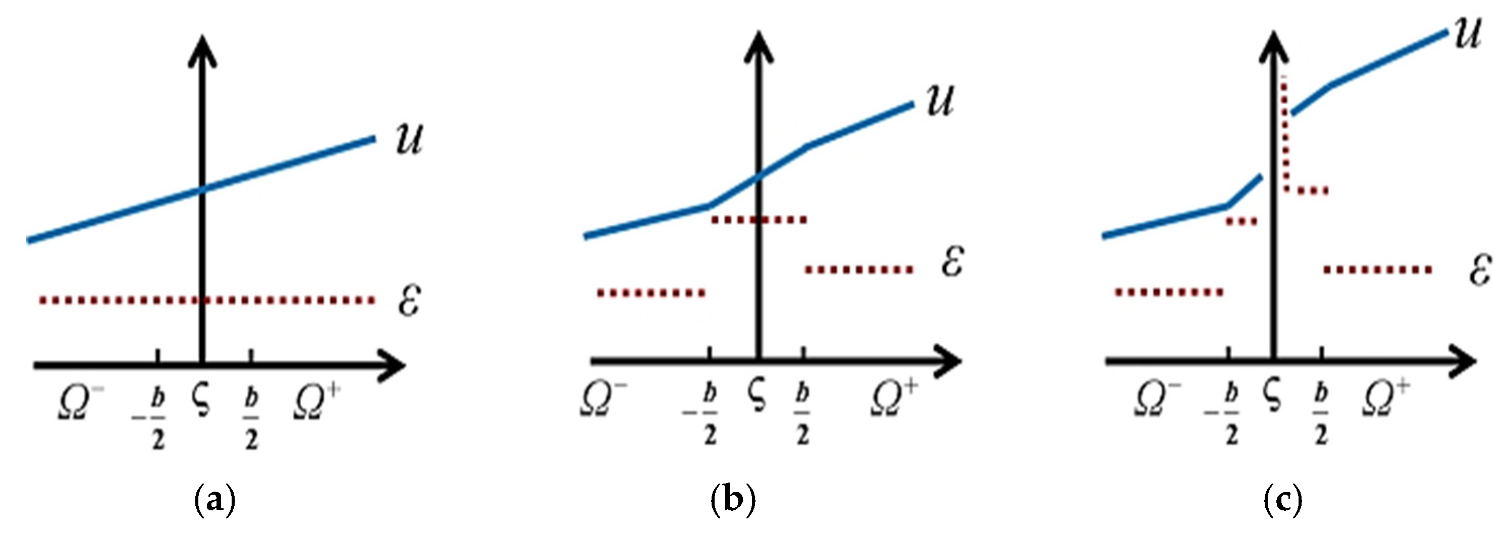
The first is the propagation of local brittle failure induced by displacement instability [1]. In this mode, displacement instability within the geotechnical material serves as the primary mechanism leading to failure in localized regions. As external forces are applied to the material, discontinuous displacements occur in localized areas, subsequently triggering strain localization and the propagation of failure. This mode is relatively common in certain brittle rock-like materials. For such materials, shear bands typically exhibit a small initial characteristic width or thickness. As the shear band further develops, its thickness decreases to nearly zero. Mathematically, this manifests as a displacement jump along the sliding surface within the continuum. The strain generated by this displacement field follows a Delta function distribution along the discontinuous surface, allowing the plastic deformation to be considered confined to these discontinuous surfaces. Consequently, the influence of shear band thickness on numerical calculation results can be neglected. A schematic diagram of the progressive deformation of shear bands in brittle rock-like materials is shown in Figure 1. The corresponding displacement and strain fields are illustrated in Figure 2. These diagrams depict the formation and development of shear bands, as well as the distribution of displacement and strain within the geotechnical material.
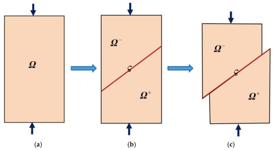
Figure 1.
Schematic of the localized deformation process of brittle rock materials: (a) continuum; (b) weak discontinuity; (c) strong discontinuity.

Figure 2.
Schematics of displacement field and strain field in the process of gradual deformation of brittle rock materials: (a) continuum; (b) weak discontinuity; (c) strong discontinuity.
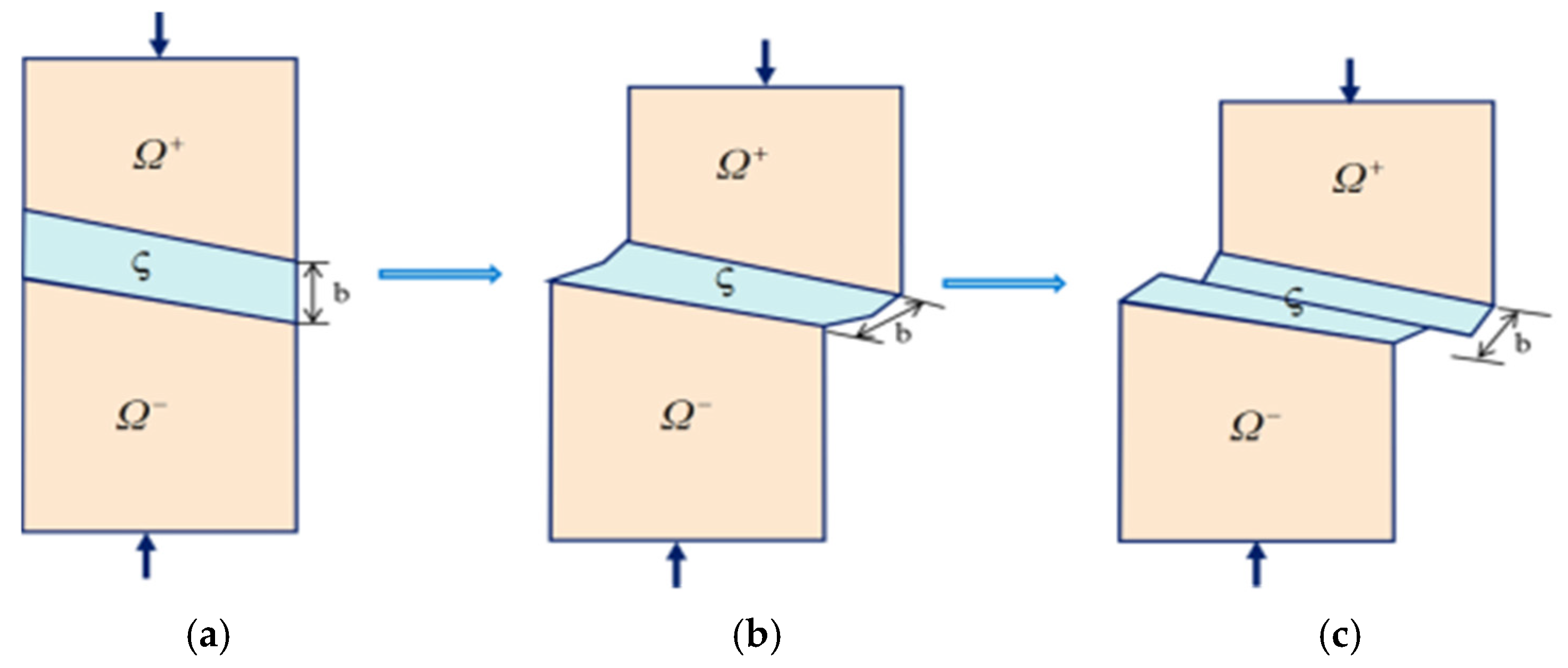
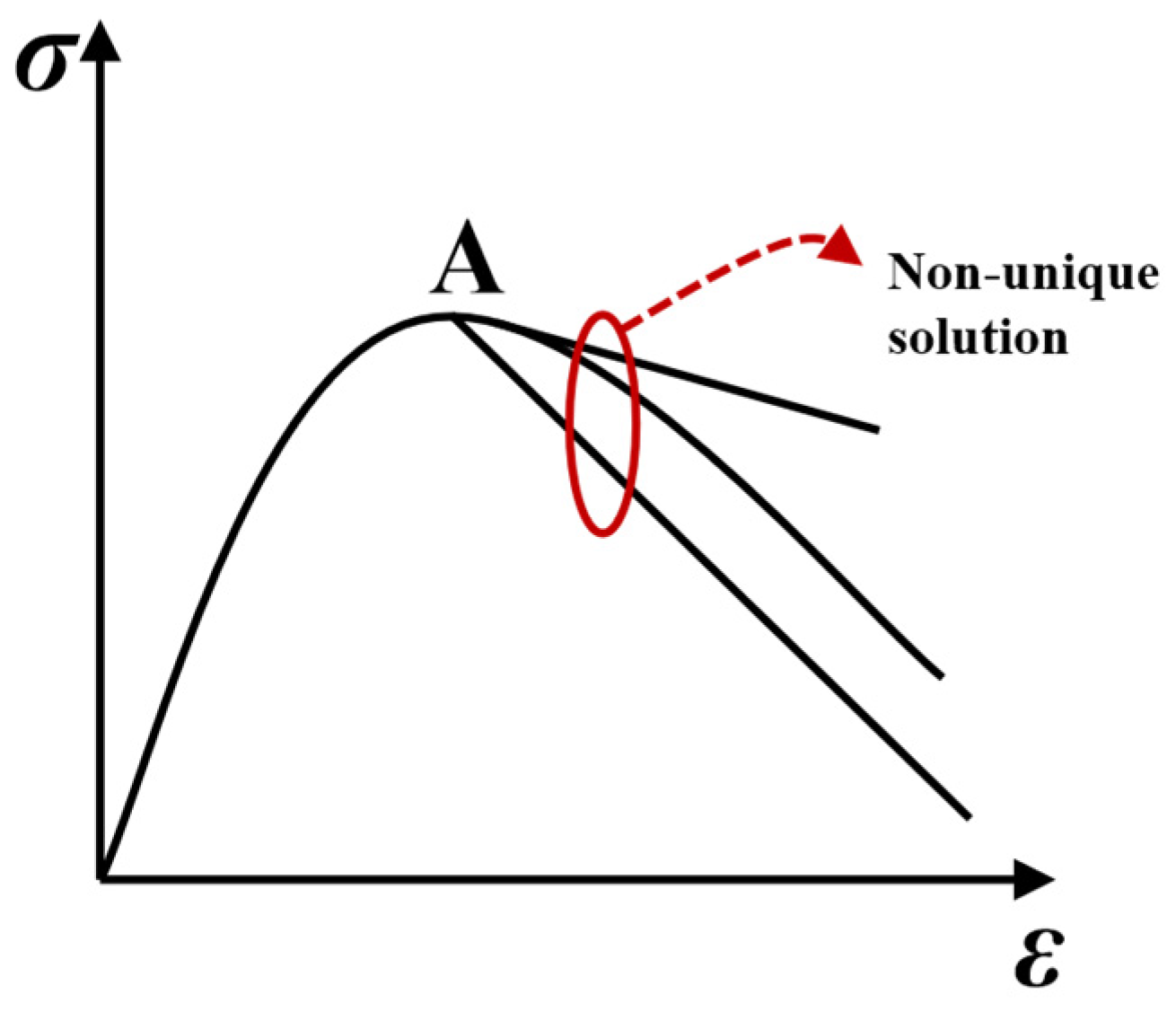
The other mode is the weak-to-strong discontinuous progressive failure mode characterized by the coupling of shear bands and slip surfaces [2,3]. In this mode, the interaction and mutual influence between shear bands and slip surfaces within the geotechnical material lead to a complex and discontinuous process of deformation and failure. The formation and propagation of shear bands induce local strain concentration, which further promotes the development of slip surfaces. This coupled mode is relatively common in semi-brittle cohesive frictional materials such as cohesive soils and soft rocks. In these materials, deformation typically manifests in the form of shear bands. The thickness of a shear band is usually 10 to 30 times the average grain size. While this is small relative to the macroscopic dimensions of geotechnical structures, it is not negligible compared to the microscopic grain size of the geotechnical material. The formation of shear bands primarily results from the rearrangement and sliding of microscopic particles within the material under stress, leading to localized deformation. In semi-brittle cohesive frictional materials like soft rocks and soils, observed shear bands often possess a finite thickness. Therefore, describing the formation and sliding process of a shear band solely by a displacement jump may be insufficient. To more accurately describe the deformation process within the localization zone, constitutive models with an internal length scale are required to capture the evolution from an initial finite width to a slip surface. This process represents the transition from weak discontinuity to strong discontinuity in the geotechnical material. The thickness of the shear band has a significant impact on numerical simulation results; hence, the influence of the shear band zone must be considered in numerical calculations. Figure 3 schematically illustrates the progressive deformation of a shear band in a semi-brittle cohesive frictional material, and Figure 4 shows the corresponding displacement and strain fields.
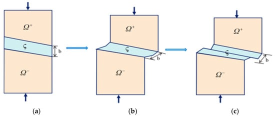
Figure 3.
Schematic of the localized deformation process of semi-brittle cohesive friction materials: (a) continuum; (b) weak discontinuity; (c) strong discontinuity.
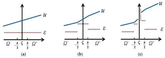
Figure 4.
Schematics of displacement field and strain field in the process of gradual deformation of semi-brittle cohesive friction materials: (a) continuum; (b) weak discontinuity; (c) strong discontinuity.
This paper is a review paper that primarily focuses on the issue of strain localization in geotechnical materials, which is a significant topic in geotechnical mechanics. Despite the prevalence of research on strain localization in geotechnical materials, there remains a lack of systematic review papers addressing this theme. This review aims to provide a comprehensive overview of the theoretical, experimental, and numerical advances in strain localization research within the field of geotechnical materials. By synthesizing findings from recent studies, this review will highlight the current state of the art in understanding strain localization phenomena and identify key areas for future research. While it is recognized that multi-field coupling (e.g., hydro-mechanical, thermo-hydro-mechanical) significantly influences strain localization behavior in geotechnical materials, a detailed review of such coupled processes is beyond the scope of this paper, which focuses primarily on mechanical aspects of localization under monotonic loading. Through this endeavor, we hope to contribute to the development of more robust and reliable methods for predicting and mitigating failure in geotechnical structures.
2. Theoretical Modeling
2.1. Classical Geotechnical Mechanics Modeling
In classical geomechanics, research on strain localization in geomaterials primarily focuses on the inclination angle of shear bands, i.e., the angle between the shear band interface and the direction of the minor principal stress. The most widely applied theories in classical geomechanics include the Mohr–Coulomb theory, Roscoe theory, and Arthur theory. According to the Mohr–Coulomb theory, the orientation of the shear band is parallel to the shear failure surface corresponding to the failure envelope, with a theoretical value of 45° + φ/2 (where φ is the material’s internal friction angle). However, the Mohr–Coulomb theory does not consider the influence of the intermediate principal stress. The Roscoe theory suggests that the shear band direction is parallel to the zero-extension plane, i.e., the direction of the slip surface generated by displacement, with a theoretical value of 45° + ψ/2 (where ψ is the material’s dilation angle). When the associated flow rule is adopted, the solutions of the Roscoe theory and the Mohr–Coulomb theory become identical. The Arthur theory takes the average of the Mohr–Coulomb and Roscoe theoretical solutions [4], yielding a theoretical value of 45° + φ/4 + ψ/4. Studies have shown that the Arthur theory solution exhibits the closest agreement with experimental values [5].
The classical geomechanics only provides a macroscopic characterization of shear band inclination and fails to accurately predict the conditions for shear band formation or their evolutionary trends.
2.2. Bifurcation Theory Modeling
As an important tool for analyzing material instability and failure phenomena, bifurcation theory provides an effective approach for studying strain localization shear bands. Bifurcation theory can determine the conditions for strain localization initiation and its development direction in materials. The strain localization phenomenon can be regarded as a form of material instability within the stress–strain relationship, mathematically manifested as the loss of uniqueness in the solution of the incremental equilibrium equations. Figure 5 illustrates the bifurcation phenomenon in the constitutive relationship of geomaterials, where point A represents the transition between strain hardening and strain softening.
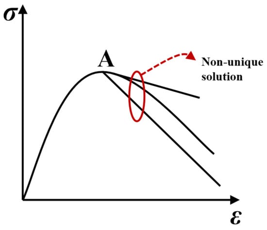
Figure 5.
Bifurcation of geomaterials.
Bifurcation theory originally emerged as a mathematical concept, proposing that when a specific parameter in a system crosses a critical threshold, the system’s behavior undergoes qualitative changes—a key characteristic of bifurcation. If no such qualitative behavioral shift occurs within the parameter’s variation range, the system remains stable. The study of bifurcation theory can be traced back to 1744 when Euler first observed bifurcation phenomena while investigating the stability of compressed columns [6]. Poincaré’s bifurcation theory framework [7] can be regarded as the earliest application of bifurcation theory in the field of mechanics. Later, in 1903, the mathematician Hadamard studied strain localization in solid materials and proposed necessary conditions for assessing the stability of equation solutions [8], laying an important foundation for understanding material instability and strain localization phenomena. Hill [9] introduced hypotheses regarding the uniqueness and stability of elastoplastic bodies under finite deformation. Subsequently, scholars such as Thomas [10], Hill [11], Mandel [12], and Rice [13] linked strain localization to material instability and bifurcation phenomena, establishing a series of widely accepted theoretical frameworks. Based on these bifurcation theories, Rudnicki and Rice [14] investigated the conditions for strain localization in pressure-sensitive dilatant materials. Meanwhile, Rudnicki and Ottosen [15] determined the conditions and evolutionary directions of strain localization in elastoplastic materials under plane stress and plane strain conditions using discontinuous bifurcation theory. Thereafter, Ottosen [16] derived analytical solutions for the critical hardening modulus and localization direction under non-associated flow conditions using spectral analysis. Neilsen and Schreyer [17], de Borst et al. [18], and Tomita [19] provided comprehensive reviews and discussions of these bifurcation theories. These pioneering works established necessary conditions for the occurrence of strain localization and formed the theoretical foundation for its study. The core viewpoint of this theoretical framework is that the onset of strain localization leads to material instability, and for static problems, the incremental equilibrium equations lose ellipticity. According to Drucker’s postulate [20], under small deformation conditions, if a material is stable, the second-order plastic work must be non-negative, i.e., the relationship between stress rate and plastic strain rate must satisfy the following equation
Hill [9] replaced the plastic strain rate in Drucker’s postulate with the total strain rate , proposing that for a material to be stable, the following condition must be satisfied
where is the elastic strain rate. When Equation (2) is taken as an equality, it becomes the necessary condition for material bifurcation, which is referred to as the general bifurcation criterion. When the plastic flow of the material follows the associated flow rule, the general bifurcation criterion is consistent with the stability criterion of Drucker’s postulate. However, when the plastic flow obeys a non-associated flow rule, the non-negative second-order plastic work stability criterion in Drucker’s postulate predicts material instability earlier than the general bifurcation criterion.
Valanis [21] proposed that the instability point of a material corresponds to the limit point where the stress rate becomes zero, meaning that at this point, the tangent modulus matrix possesses a zero eigenvalue. The corresponding expression is
Thus, the condition for material bifurcation is
When the plastic flow of the material follows the associated flow rule, the limit point instability criterion is consistent with both the general bifurcation criterion and the stability criterion of Drucker’s postulate.
Under the assumption of small deformations, when plastic flow follows the associated rule, bifurcation phenomena occur only when the material exhibits strain softening. Neilsen and Schreyer [17] hypothesized that before the material undergoes bifurcation, the material inside and outside the shear band maintains geometric compatibility, and the strain rates vary continuously. This assumption ensures that, at the onset of bifurcation, the material inside and outside the shear band possesses the same tangent modulus. Based on this assumption, the following relationship can be derived
where represents the acoustic tensor, is the unit normal vector to the localization deformation surface, and is the unit direction vector of the localization deformation surface. When is perpendicular to , the localized deformation manifests as a shear mode; when is parallel to , it exhibits a tensile cracking mode; when the relationship between the two vectors falls between these two extremes, the localized deformation appears as a mixed mode of shear and tensile cracking. The occurrence of material bifurcation implies the initiation of localization, which necessitates that must have a solution. Therefore, the following condition must be satisfied
The aforementioned bifurcation theory forms the foundation for addressing strain localization problems within the theoretical framework of classical continuum mechanics. When applying the above theories to solve strain localization problems, the first step is to utilize bifurcation criteria to determine whether strain localization occurs. If strain localization is identified, it becomes necessary to adopt models capable of reflecting the material’s post-bifurcation deformation behavior. This approach is commonly used to analyze the occurrence of instability and failure in solid materials, including soils. However, bifurcation theory also has certain limitations: firstly, it cannot guarantee the uniqueness of solutions near the bifurcation point, and due to the singularity of the stiffness matrix, computational accuracy is difficult to ensure; secondly, bifurcation analysis cannot describe the thickness of shear bands or the post-localization behavior.
3. Experimental Observations
Experimental investigation is one of the most direct and crucial approaches in the study of strain localization, which can be classified into two categories: laboratory tests and in situ tests. In situ tests are less frequently used due to limitations such as restricted applicability, high costs, and significant experimental risks. In contrast, laboratory tests are widely employed to investigate the mechanisms of strain localization. In recent years, the advent of advanced measuring instruments, such as scanning electron microscopes (SEM), X-ray diffractometers, acoustic emission detectors, and nuclear magnetic resonance spectrometers, has significantly advanced experimental research on localized deformation in geotechnical materials. Common laboratory testing methods include direct shear tests, plane strain tests, and triaxial tests, among others.
Morgenstern and Tchalenko [22] were the first to use a direct shear apparatus to study shear bands in geotechnical materials, investigating the shear deformation of kaolin under direct shear from a microscopic perspective. Later, Roscoe [23] applied X-ray technology to experimental research, observing banded localized deformation phenomena in both simple shear tests and retaining wall centrifuge model experiments, which he termed shear bands. Scarpelli and Wood [24] employed X-ray technology to study shear bands in direct shear tests on sand, discovering that the thickness of the shear bands was related to particle size, with the shear band thickness being approximately 10 times the average grain diameter. Although direct shear tests offer advantages such as simple operation and convenient sample preparation, during the shearing process, the principal stress planes of the specimen continuously rotate, and the shear plane is entirely confined within the plane between the upper and lower boxes, rather than failing along weak planes. These factors make it difficult for direct shear tests to effectively analyze the deformation mechanisms within shear bands.
The advent of conventional axisymmetric triaxial testing apparatus further advanced the study of localized shear bands. The stress state in conventional axisymmetric triaxial tests exhibits axisymmetric characteristics, which is more clearly defined compared to direct shear apparatus. Bishop and Henkel [25] conducted conventional triaxial compression tests on sand, investigating the influence of end constraints and specimen size on localized deformation. Arthur and Dunstan [26] studied the orientation of rupture layers in sand through conventional triaxial tests, revealing that variations in average effective stress level and particle shape had minimal impact on rupture layer orientation. Lade et al. [27] performed conventional triaxial compression tests on clay, examining its localized deformation under different stress conditions. Vardoulakis [28] conducted a bifurcation analysis on strain-hardening dilatant sand specimens via triaxial tests, demonstrating that localized deformation occurs when the specimen density is sufficiently high or the lateral pressure exceeds a critical value. Hettler and Vardoulakis [29] used a large-scale triaxial device to test sand, finding that bifurcation occurs in the softening segment of the stress–strain curve and that the width of the localization zone correlates with particle size. Desrues et al. [30] investigated localized deformation in sand through conventional triaxial tests and predicted the initiation and development of shear bands. Alshibli et al. [31] studied the effects of loading conditions and confining pressure on the strength characteristics and localized deformation of sand using conventional triaxial compression tests, employing computed tomography and digital imaging techniques to examine the evolution of shear bands. Meng et al. [32] conducted high-temperature conventional triaxial compression tests on shale, analyzing the influence of temperature on material deformation; results indicated that thermal stresses generated at high temperatures play a significant role in regulating deformation and inhibiting crack propagation. Despite the widespread application of conventional triaxial tests in axisymmetric problems, they possess certain limitations. For instance, these tests typically use cylindrical specimens, making it difficult to observe the process of localized deformation. Furthermore, practical engineering often involves plane strain and three-dimensional problems, such as slopes, dams, and foundations, which restricts the applicability of conventional triaxial tests.
Currently, plane strain tests are widely used to study the development, formation, and influencing factors of strain localization in geomaterials. The plane strain test apparatus offers advantages such as simple operation, convenient sample preparation, ease of capturing localized deformation processes, and straightforward measurement of shear band inclination. Although plane strain tests involve three-dimensional stress states, the strain along one principal stress axis is zero, allowing simplification to a two-dimensional plane strain condition for analysis. Vardoulakis [33] investigated shear bands in sand through plane strain tests, revealing that shear bands appear during the hardening stage and their inclination approximates the average of the Mohr–Coulomb and Roscoe theoretical values. Vardoulakis and Graf [34] studied strain localization in sand using plane strain tests, deriving bifurcation conditions and inclination angles for shear bands under different constitutive equations. Vermeer [35] conducted plane strain tests on sand, demonstrating that both shear band inclination and thickness correlate with particle size: finer grains result in thinner shear bands; the inclination angle of coarse sand aligns more closely with the Roscoe theoretical value, while that of fine sand approaches the Mohr–Coulomb theoretical value. Han and Vardoulakis [36] employed X-ray technology in plane strain tests to observe deformation characteristics of saturated fine sand before and after failure, discussing internal fluid flow and rate sensitivity issues related to mathematical stability. Later, Han and Drescher [37] performed plane strain compression tests on a type of coarse sand, examining the state and propagation direction of shear band deformation. Labuz et al. [38] developed a novel plane strain device to test rocks and concrete, combining the advantages of conventional triaxial compression and direct shear tests, which allows failure surfaces to develop and propagate unrestricted. Finno et al. [39] conducted plane strain tests on loose sand under both drained and undrained conditions, integrating local measurements of boundary forces and deformations with stereophotogrammetry to observe the complete process of strain localization transitioning from homogeneous to heterogeneous deformation during plane strain compression. Alshibli and Sture [40] performed high and low confining pressure plane strain tests under varying conditions, investigating the effects of sample density, confining pressure, sand particle size, and shape on the constitutive and stability behavior of granular materials. The results indicated that these factors significantly influence localized deformation and stress–strain relationships. Alshibli et al. [31] compared plane strain test results on sand with triaxial test outcomes, demonstrating that specimen failure under plane strain loading exhibits more pronounced shear band characteristics.
Both plane strain tests and conventional axisymmetric triaxial tests fail to consider the influence of the intermediate principal stress, thus they cannot accurately reflect the true characteristics of strain localization. To more realistically simulate the formation of shear bands under complex stress states during strain localization, many scholars have employed true triaxial apparatuses for experimental investigations. In fact, plane strain tests and conventional axisymmetric triaxial tests represent special cases of true triaxial stress states. Research on strain localization based on true triaxial tests holds greater reference value. Chu et al. [41] investigated strain localization in sand through true triaxial tests by setting different intermediate principal stress ratios, studying the relationship between axial strain and shear band development. Their research found that strain softening is path-dependent and can occur not only due to shear band formation but also in the absence of any heterogeneous deformation. Wang and Lade [42] conducted a series of true triaxial tests on dense sand under fixed intermediate principal stress ratios. Their study revealed two types of failure mechanisms for dense sand with different intermediate principal stress ratios: one being peak-smooth failure followed by post-peak softening, and the other being shear band failure occurring in a plastic hardening state. Rodriguez and Lade [43] performed true triaxial tests on transversely isotropic sediments of Nevada fine sand and investigated the inclination of shear bands, with results showing the closest agreement with the Arthur solution. Minaeian et al. [44] studied the deformation characteristics of synthetic sandstone through true triaxial tests, demonstrating that lateral pressure significantly influences the mechanical response of rocks. Increasing the intermediate principal stress can enhance the compressive strength of specimens by more than two times in some cases. By adjusting the intermediate principal stress ratio, true triaxial tests can simulate the behavior of geomaterials under arbitrary three-dimensional stress states, such as plane strain conditions and axisymmetric compression states. However, the fabrication and operation of true triaxial apparatuses are relatively complex and require high operational expertise. Additionally, theoretical and numerical limitations in three-dimensional analysis also restrict the application of true triaxial tests in studying strain localization.
To provide a systematic overview of the experimental techniques used in strain localization studies, Table 1 summarizes the key test methods, measurement technologies, and typical shear band characteristics (such as thickness and inclination) reported in the literature. This comparison highlights the capabilities and limitations of each method, facilitating a better understanding of their applicability in capturing shear band behavior under different loading and boundary conditions.

Table 1.
Summary of experimental methods for studying strain localization in geotechnical materials.
4. Numerical Simulation
With the advancement of computer technology, numerical techniques have provided effective tools for the study of strain localization. Due to advantages such as repeatability and low cost, numerical methods are widely employed to simulate strain localization alongside theoretical and experimental research. Common numerical methods include: the Finite Element Method (FEM) [45,46,47,48], Discrete Element Method (DEM) [49,50,51], Boundary Element Method (BEM) [52,53,54], Finite Difference Method [55,56,57], Meshfree Methods [58,59,60], and Multiscale Methods [61,62,63]. Currently, the Finite Element Method demonstrates the most extensive applicability in simulating practical engineering problems.
4.1. Classical Finite Element Method Numerical Simulation
The finite element technique, combined with appropriate constitutive models, provides a powerful tool for simulating the development of shear bands in geomaterials [64,65,66]. However, classical finite element methods exhibit significant limitations in the numerical simulation of strain localization problems. Classical finite element techniques are based on classical continuum theory, which assumes that materials are continuously distributed in space. This assumption is reasonable when describing homogeneous deformation of materials. However, when strain localization occurs, the assumption of material homogeneity no longer holds due to the high stress and strain gradients within the localization zone. From a mathematical perspective, when strain localization occurs in the simulation of non-cohesive materials, the partial differential equations for quasi-static problems change from elliptic to hyperbolic type, while those for dynamic problems change from hyperbolic to elliptic type, leading to ill-posedness in solving initial-boundary value problems. The absence of an internal length scale in classical finite element methods makes it impossible to determine the thickness of shear bands, resulting in mesh-dependent finite element solutions. Additionally, the arrangement of the mesh in classical finite elements can influence the location and orientation of shear bands. Consequently, classical finite element methods face considerable difficulties in numerically simulating non-associated plastic flow or strain-softening inelastic material responses.
The introduction of regularization mechanisms can resolve the ill-posed boundary value problems encountered when simulating strain localization in geomaterials using classical finite element methods. Currently, widely used regularization models are primarily divided into diffuse crack models and discrete crack models [67].
4.2. Weak Discontinuity Method Numerical Simulation
Diffuse models enrich the continuum by introducing an internal or characteristic length scale through non-conventional constitutive relations, primarily including Cosserat continuum theory [68,69,70,71,72], non-local models [73,74,75,76,77], gradient plasticity models [78,79,80,81,82], and viscoplastic models [83,84]. During mesh refinement, these diffuse models ensure that energy dissipation occurs within strain-localized shear bands of a certain width, which is considered related to the internal length scale. These regularized diffuse models are commonly used to analyze problems involving weak discontinuities in geomaterials (where displacements are continuous but strains are discontinuous), with shear bands typically exhibiting finite thickness. Among these, the most frequently applied is Cosserat continuum theory.
Cosserat continuum theory, also known as micropolar theory, has two main features: first, it introduces rotational degrees of freedom on the basis of the classical continuum description; second, it incorporates an internal scale parameter into the constitutive equations of classical solid mechanics. Correspondingly, micro-curvature (the spatial derivative of the rotational degrees of freedom) and couple stresses (the energy conjugates of micro-curvature) are introduced into the strain and stress vectors of the classical finite element method, respectively. These two main features endow Cosserat continuum theory with two significant advantages in simulating strain localization and progressive failure in geomaterials: first, it enables the simulation of mesh-independent solutions and shear band thickness (due to the introduction of the internal length scale); second, the introduction of rotational degrees of freedom allows for a natural description of particle rotations in geomaterials, as the mechanical response of the material in the failure zone is closely related to the displacements and rotations of particles within a certain range.
Cosserat continuum theory was first proposed by the French Cosserat brothers, Eugene and Francois, in 1909 based on asymmetric elasticity theory [85]. However, the theory did not gain widespread attention after its introduction. It was not until about 50 years later that people began to recognize that material strength is influenced by strain gradients. Cosserat continuum theory, which accounts for the effects of rotation gradients and can phenomenologically reflect the scale effects of materials, was thus widely applied in the simulation of layered rock masses. Subsequently, Mindlin [86], Sternberg and Muki [87] applied Cosserat continuum theory to solve problems involving circular holes and fractures, investigating the influence of couple stresses on stress concentration. Approximately 20 years later, Cosserat continuum theory was genuinely applied to strain localization. Mühlhaus and Vardoulakis [88] were the first to use Cosserat continuum theory to study the location and thickness of shear bands. Later, Papanastasiou and Vardoulakis [89] employed Cosserat continuum theory to investigate progressive localization related to borehole stability. de Borst et al. [18] first developed a pressure-dependent J2 plasticity model within the Cosserat continuum framework and derived a return mapping algorithm for the integration of constitutive equations. Iordache and Willam [71] studied the regularization properties of discontinuous bifurcation in higher-order micropolar continua incorporating an internal length scale. Ord et al. [90] investigated the microstructural development of shear bands in dense granular soils, demonstrating that particle rotation significantly influences the deformation and failure of shear bands in granular materials and emphasizing that the effects of particle rolling cannot be neglected when studying shear deformation. Papanastasiou and Zervos [91] reviewed the application of enhanced gradient elasto-plastic models and Cosserat continuum theory in simulating wellbore instability. Khoei and Karimi [92] developed an extended finite element method for higher-order continua based on Cosserat continuum theory to simulate localized deformation processes in geotechnical engineering, achieving mesh-independent numerical solutions. Li and Tang [93] derived a consistent algorithm for a pressure-dependent Drucker-Prager elasto-plastic model within the Cosserat framework and applied it to strain localization analysis under plane strain conditions. Zhang et al. [94] established a parametric variational principle-based analytical framework for Cosserat continua. Chen et al. [95] derived a flexible polygonal Cosserat continuum analysis method based on the scaled boundary finite element theory and used it to study stress concentration problems around embedded holes in various structures. Tang et al. [96,97,98,99] established a low-order mixed finite element method, an axisymmetric model, an anisotropic elasto-plastic model, and an isogeometric analysis method within the Cosserat continuum framework to investigate strain localization in geomaterials.
The results demonstrated that the Cosserat model can overcome mesh dependency caused by strain localization and simulate shear bands with finite thickness. However, Jirásek and Zimmerman [100,101] found that when diffuse models are used to simulate fracture and strongly discontinuous shear band problems, spurious stress transfer occurs because finite element interpolations based on continuum theory cannot reproduce the discontinuous nature of the actual displacement field around open macroscopic cracks. Therefore, while Cosserat continuum theory is not suitable for analyzing strongly discontinuous shear bands and brittle failure, it holds certain advantages in simulating weakly discontinuous shear failure in geomaterials.
The Cosserat continuum introduces rotational degrees of freedom. Taking two-dimensional problems as an example, each material point has three degrees of freedom
where is the displacement vector in Cosserat continuum theory, and is the rotational degree of freedom.
For quasi-static problems, the equilibrium equations can be expressed as
where , and represent the stress vector, differential operator, and body force vector in Cosserat continuum theory, respectively, defined as
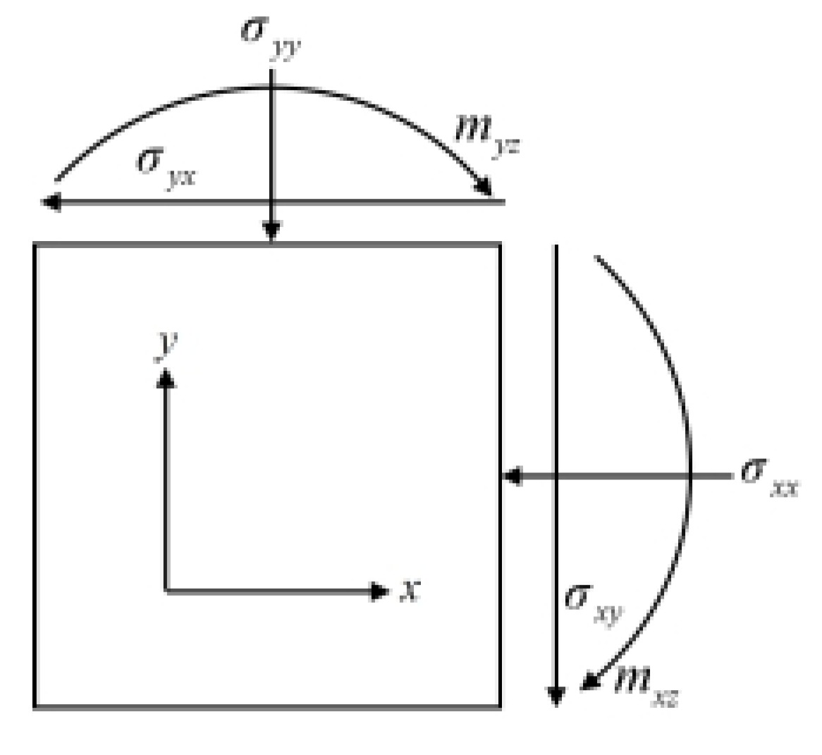
where and represent the couple stresses (as shown in Figure 6), denotes the body couples, and is the internal length parameter. The internal length parameter is typically related to microstructural properties (such as particle size, particle shape, and surface roughness) and micro-strength parameters (e.g., particle hardness). Its value is usually determined experimentally. In general, it is difficult to specify the exact internal parameters for real geomaterial particles. Considering the regularization effect in numerical computations, Tejchman and Bauer suggested [102] that if the finite element size does not exceed five times the internal length parameter (i.e., ), the computed thickness of the shear band becomes almost independent of the spatial discretization.
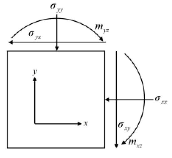
Figure 6.
Schematic of the stress components of the two-dimensional Cosserat continuum on the principal plane of the material.
The kinematic equations can be defined as
where is the strain vector in Cosserat continuum theory, defined as
where and represent the micro-curvatures in Cosserat continuum theory [93].
Conceptually, the Cosserat continuum approach is particularly suitable for modeling strain localization in granular or cohesive–frictional materials where the shear band possesses a finite thickness and the micro-rotational behavior of particles plays a significant role in the mechanical response. It is appropriate for problems involving weak discontinuities, such as the development of shear bands in soils or soft rocks before the formation of a distinct slip surface. The introduction of an internal length scale allows the model to capture the thickness of the shear band and avoid mesh dependency, making it advantageous for simulating the early to intermediate stages of progressive failure in geotechnical materials.
4.3. Strong Discontinuity Method Numerical Simulation
Discrete crack models fall within the category of discontinuous shape function techniques, primarily used for analyzing strongly discontinuous deformations and brittle fracture problems. Discontinuous shape function techniques simulate discontinuous deformations caused by strain localization by superimposing an additional function onto standard elemental shape functions while keeping the finite element mesh unchanged. Discrete crack models represent discontinuities as zero-thickness interfaces and introduce cohesive laws to describe the kinematic relationships across these discontinuous surfaces. These models are mainly divided into two types. The first type is the cohesive interface element model [103,104,105,106,107], which typically requires adaptive mesh reconstruction techniques to capture strongly discontinuous paths [108,109,110]. The second type is the embedded crack model, which allows discontinuities to traverse elements and includes the Strong Discontinuity Approach (SDA) [111,112,113,114,115] and the Extended Finite Element Method (XFEM) [116,117,118,119]. The main difference between these two models is that SDA enriches degrees of freedom at the element level, whereas XFEM enriches them at the node level. Oliver et al. [120] conducted a comparative study of SDA and XFEM, concluding that SDA offers higher accuracy on coarser meshes and lower computational costs compared to XFEM. Additionally, due to its use of condensation techniques, SDA is easier to implement within the classical finite element framework. The Strong Discontinuity Approach (SDA) incorporates discontinuous terms corresponding to displacements into standard finite element interpolation functions, enabling the discussion of strain localization deformation within a unified continuum framework. Compared to other methods, SDA is geometrically more intuitive and relatively easier to implement at this stage. As a result, SDA is widely applied in the analysis of brittle fracture and strain localization in materials.
The Strong Discontinuity Approach (SDA) addresses discontinuous deformation problems based on continuum theory. It derives the stress-displacement jump relationship on discontinuous surfaces from the constitutive relations of the continuum, constructing a decoupled constitutive model. SDA enriches the interpolation functions within the classical Galerkin finite element method, enabling accurate characterization of displacement discontinuities to ensure mesh-objective numerical solutions. By introducing displacement jumps into the standard finite element displacement field, SDA obtains the weak and discrete forms of the governing equations through the Assumed Enhanced Strain (AES) method [63]. This approach allows for the simulation of strong discontinuities without requiring adaptive techniques or mesh reconstruction, and does not necessitate mesh refinement. In SDA, the entire analysis is conducted within the continuum mechanics framework, permitting cracks to propagate through elements. It assumes a zero-thickness shear band, thereby maintaining the well-posedness of boundary value problems without the need for a characteristic length scale.
The Strong Discontinuity Approach was first proposed by Dvorkin et al. [121], who combined it with the finite element method to analyze fracture in simply supported beams. Subsequently, Klisinski et al. [122] introduced a simplified element formulation for SDA, which derived the fundamental equations without relying on variational principles, and applied it to simulate plate tension under plane stress conditions. Reza [123] conducted a variational derivation of strong discontinuity elements within the Hu-Washizu variational principle framework, proposing an AES-formulated SDA and applying it to numerically simulate three-point bending beams. Later, Simo and Oliver [112,115] modified the Hu-Washizu three-field variational principle, proposing an incompatible strain formulation of SDA that incorporated incompatible strains into the AES framework, reducing the three-field variational principle to an independent two-field formulation involving displacement and stress fields. The core idea of this method is to augment standard C0 finite element shape functions with incompatible approximation functions that include displacement jumps. Assuming bounded stresses, the method models the sharp variation in displacement gradients within narrow bands as Dirac delta distributions while satisfying stress continuity conditions across slip lines, thereby objectively reflecting energy dissipation after material instability. Oliver [112,124] developed an AES finite element method with asymmetric strong discontinuity structures, combining strain-softening constitutive equations to simulate strong discontinuities in solid mechanics. Regueiro and Borja [125,126] employed the AES-formulated SDA with a non-associated Drucker-Prager elastoplastic constitutive model to investigate strain localization in geotechnical structures. Over the past two decades, the AES-formulated Strong Discontinuity Approach has been successfully applied to numerous problems, including strain localization in geomaterials [63,127], localized deformation and failure analysis of beams and frame structures [128,129], seepage field analysis in fractured media [130,131], instability and failure analysis of porous media [132,133], and fracture analysis of brittle materials [3,131,134,135,136,137].
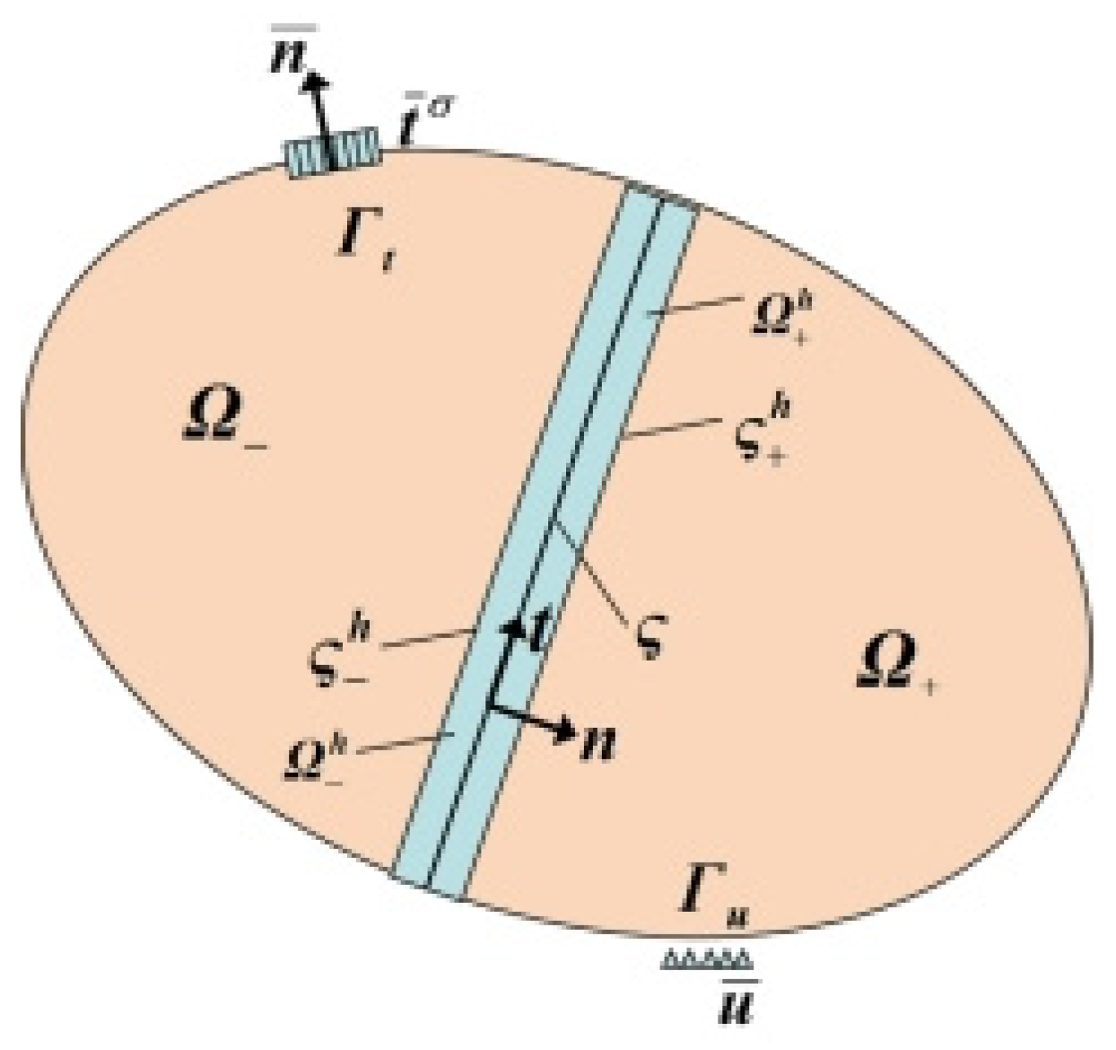
A schematic diagram of the two-dimensional Strong Discontinuity Approach (SDA) is illustrated in Figure 7. The solution domain is divided into two parts: a continuous region and a discontinuity surface . The continuous region is further separated by the discontinuity surface into two subregions, and . The core concept of the classical SDA involves adopting a classical elastoplastic constitutive model within the continuous region , while the discontinuity surface employs a constitutive law embedded with displacement discontinuities.
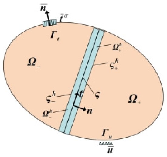
Figure 7.
The schematic diagram of the two-dimensional SDA.
Under the assumption of small deformations, the governing equations of the strong discontinuity theory are given by
in which
where is the prescribed boundary displacement, is the unit normal vector corresponding to boundary , is the stress tensor, is the prescribed boundary traction stress, denotes the jump of a certain quantity across the discontinuity line ς, Tj is the traction stress on the discontinuity line ς, and n is the unit normal vector of the discontinuity line ς
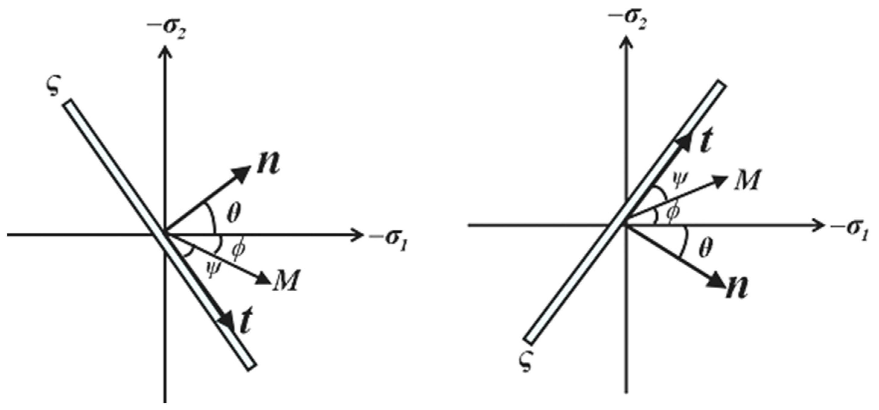
Under plane strain conditions, the unit normal vector and unit tangent vector of the discontinuity line ς are defined as
where is the angle relative to the negative direction of the major principal stress axis, as illustrated in Figure 8. The sign convention for is related to the evolution direction of the slip line, which depends on the element deformation at the onset of strain localization. This direction is determined using the theory of discontinuous bifurcation [125].
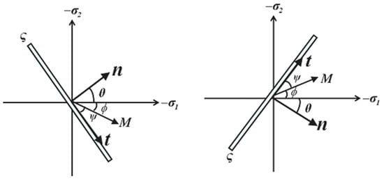
Figure 8.
Slip line orientation with respect to the negative direction of the major principal stress axis.
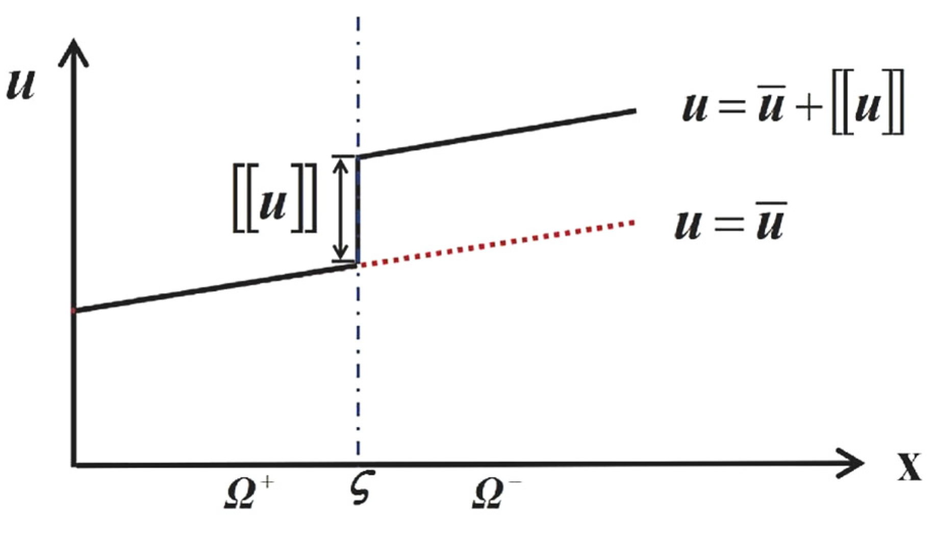
The displacement field exhibits a discontinuity when crossing the discontinuity line ς, as shown in Figure 9.
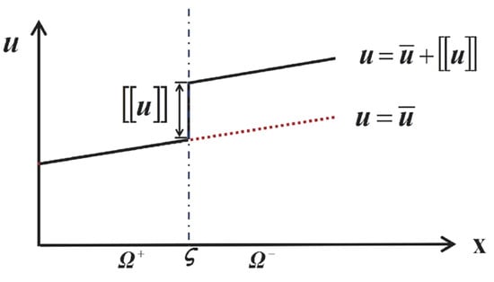
Figure 9.
Illustration of the displacement field decomposition.
The Strong Discontinuity Approach (SDA) is characterized by its ability to provide constitutive relationships on discontinuity surfaces after localized deformation occurs. SDA assumes that once localization initiates, plastic deformation becomes entirely concentrated within the discontinuity surface, incorporates softening effects, and considers elastic unloading outside the discontinuity. Although SDA can accurately capture the evolution of discontinuity surfaces (or lines) and yield mesh-independent solutions, it exhibits certain limitations when applied to strain localization analysis of geomaterials with finite shear band thickness, such as semi-brittle cohesive–frictional materials. In SDA, the deformation field is assumed to be uniformly distributed prior to the onset of strong discontinuities. In reality, deformation in such materials is typically a gradual process, with strong discontinuities often emerging after a phase of weak discontinuities. The occurrence of weak discontinuities is usually accompanied by irreversible plastic deformation and the formation of shear bands with finite thickness. However, SDA postulates that geomaterials develop a discontinuous displacement field upon instability, thereby neglecting the deformation during the weak discontinuity phase and potentially transitioning prematurely to the strong discontinuity stage. Consequently, it cannot simulate the progressive failure process from weak to strong discontinuities in such geomaterials. Additionally, for semi-brittle cohesive–frictional geomaterials, both the shear band thickness and particle rotation significantly influence mechanical properties such as strength, stiffness, and stability. SDA, by assuming a zero-thickness discontinuity surface (or line), overlooks the impact of the adjacent localized zone on the material’s mechanical response.
In contrast, the strong discontinuity approach (SDA) is more appropriate for simulating failure processes where displacement jumps across a well-defined discontinuity surface, such as in brittle fracture or the final stage of shear band evolution in rock-like materials. SDA is ideally applied to problems characterized by strong discontinuities, where the deformation localizes into a zero-thickness slip line or crack. This method is efficient for capturing post-localization behavior, such as the propagation of discrete cracks or slip surfaces, and is widely used in the analysis of brittle materials or structures where the energy dissipation is concentrated along discrete paths.
4.4. Discrete Lattice Models for Strain Localization
Discrete lattice models represent another powerful numerical approach for simulating strain localization and failure in geotechnical materials, particularly in cohesive soils and rocks. Unlike continuum-based methods, discrete lattice models idealize the material as a network of discrete elements (e.g., beams, springs, or bonds) connected at nodal points. This representation allows for the natural emergence of cracks, shear bands, and other discontinuities without the need for predefined failure paths. The discrete nature of these models makes them particularly suitable for capturing complex fracture patterns and the transition from continuous to discontinuous behavior.
One of the key advantages of discrete lattice models is their ability to incorporate material heterogeneity and microstructural features directly into the model. By assigning random properties to the discrete elements, these models can simulate the inherent variability of geotechnical materials, leading to more realistic predictions of failure mechanisms. Furthermore, discrete lattice models can be coupled with other numerical techniques, such as the Strong Discontinuity Approach (SDA), to enhance their capability in modeling localized failure.
For instance, Hadzalic et al. [138] employed a coupled discrete lattice model and strong discontinuity approach to investigate failure mechanisms in soil–foundation systems. Their study demonstrated the model’s ability to capture complex failure patterns, including shear band formation and crack propagation, under various loading conditions. Similarly, Nikolic and Ibrahimbegovic [139] developed a rock mechanics model using a discrete lattice framework capable of representing initial heterogeneities and a full set of 3D failure mechanisms. Their work highlighted the model’s effectiveness in simulating brittle fracture and strain localization in rocks, providing insights into the influence of microstructural defects on macroscopic behavior.
Despite their advantages, discrete lattice models also present challenges, such as high computational cost for large-scale problems and the need for careful calibration of micro-parameters. However, ongoing advancements in computational power and model optimization continue to expand their applicability in geotechnical engineering.
4.5. Innovative Research on Weak–Strong Discontinuous Coupling Numerical Methods
In recent years, to address the need for refined modeling of the progressive failure process from weak to strong discontinuities in geomaterials, several theoretical breakthroughs have emerged in this field: Tang and Li et al. [140] developed a two-dimensional Cos-SDA composite model by coupling Cosserat continuum theory with the SDA framework, achieving for the first time the simulation of the entire process from weak discontinuities (strain localization) to strong discontinuities (slip failure) in geomaterials. As a theoretical supplement, Li et al. [141] conducted a regularization mechanism study of this model based on spectral analysis theory, systematically revealing the energy dissipation mechanism of non-local effects during the weak-to-strong discontinuity transition, thereby enriching the physical connotation of the model. Notably, Li et al. [142] further broke through the limitations of isotropic assumptions and developed a two-dimensional anisotropic elastoplastic SDA constitutive model. By introducing a direction-dependent damage evolution criterion, this model successfully simulated the progressive failure path of brittle layered rock-like materials from continuous deformation to discontinuous fracture, providing a new paradigm for the unified Cos-SDA modeling of progressive weak-to-strong discontinuity failure in complex geological materials. This series of studies on weak–strong discontinuity coupling numerical methods has established a unified numerical framework for progressive failure analysis, bridging the theoretical gap between traditional continuum mechanics and discrete crack models.
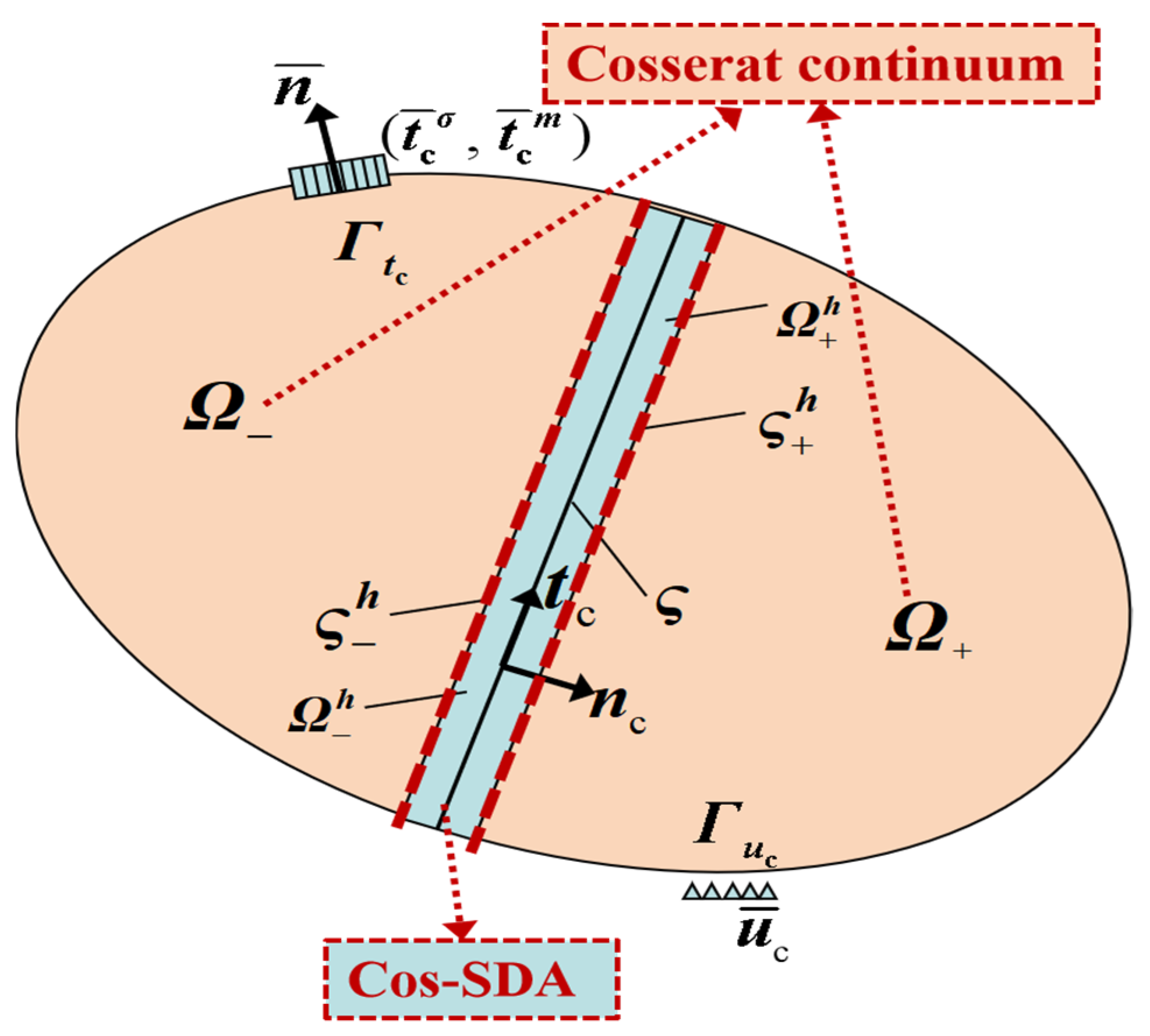
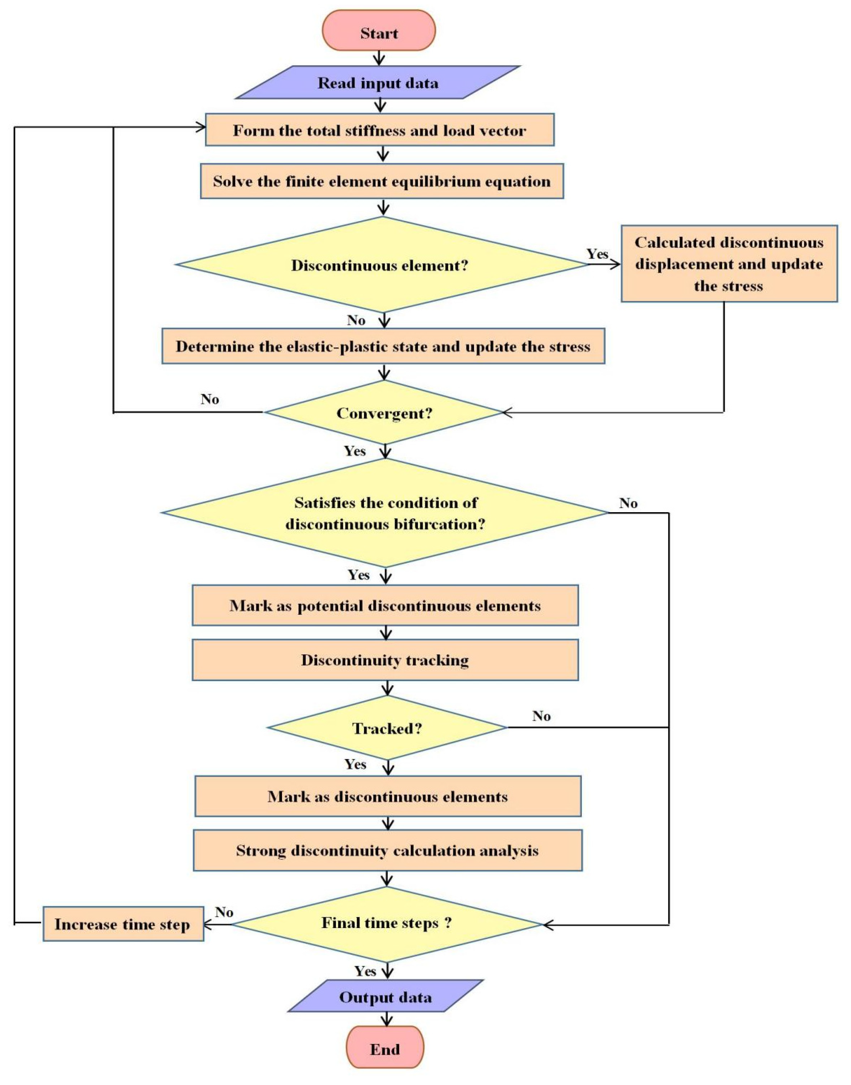
A schematic diagram of the incremental boundary value problem (BVP) for the two-dimensional Cos-SDA model is shown in Figure 10. The primary distinction between the Cos-SDA model and the SDA model lies in the Cos-SDA model’s ability to simulate the continuous–discontinuous deformation process involving weak-to-strong discontinuities. It captures the progression of material strain localization from shear band development to slip failure. The continuous part is modeled using Cosserat continuum theory, while the discontinuity line is modeled using the Strong Discontinuity Approach within the Cosserat continuum framework. The implementation framework of the Cos-SDA model is illustrated in Figure 11.
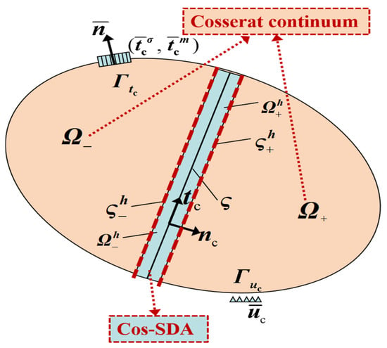
Figure 10.
The schematic diagram of the two-dimensional Cos-SDA.
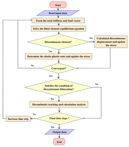
Figure 11.
The implementation framework of the Cos-SDA.
By simplifying static problems into boundary value problems of partial differential equations, the governing equations of the Strong Discontinuity Approach within the framework of Cosserat continuum theory are as follows
where and represent the prescribed boundary traction stress and traction couple stress, respectively; and denote the traction stress and traction couple stress on the discontinuity line , respectively; and is the couple stress tensor, defined as
Within the framework of Cosserat continuum theory, the unit normal vector and unit tangent vector of the discontinuity line are respectively defined as
In terms of model validation, the Cos-SDA framework has been applied to several benchmark problems. For instance, simulations of biaxial compression tests on cohesive–frictional soils have demonstrated its capability to realistically capture the evolution of shear bands from initial thickening (weak discontinuity) to final slip surface formation (strong discontinuity), with results aligning well with experimental observations regarding failure modes and load–displacement curves [140,141]. Furthermore, its application to slope stability analysis has showcased the model’s effectiveness in simulating progressive failure from internal strain localization to the development of a continuous sliding surface.
Regarding practical implementation, the determination of parameters, particularly the internal length scale in the Cosserat continuum, remains a subject of ongoing research. This parameter is often correlated with the average particle size of the granular material or calibrated against measured shear band widths. The strength and softening parameters for the SDA component can be inferred from conventional laboratory tests, such as direct shear or triaxial tests, supplemented by inverse analysis techniques.
A significant current constraint of the Cos-SDA model lies in its predominant formulation and application within a 2D setting. Extending this coupled approach to three dimensions presents substantial challenges, including the complex description of arbitrary discontinuity surface initiation and propagation in 3D space, and the considerable increase in computational demand. Overcoming these limitations to achieve efficient 3D Cos-SDA analysis represents a crucial and challenging direction for future development.
4.6. Spectral Analysis of the Regularization Effect of Numerical Methods
The use of inappropriate numerical methods to simulate strain localization in geomaterials often leads to ill-posed boundary value problems. Traditional finite element methods, based on classical continuum theory, lack an internal length scale that can reflect changes in the material’s microstructure. Consequently, when addressing strain softening and localization issues, these methods often exhibit mesh dependency, meaning the thickness of the shear band varies with changes in mesh density. The root cause of this mesh dependency lies in the ill-posed nature of the boundary value problems involving shear bands. For instance, in quasi-static problems, the governing equations transition from elliptic to hyperbolic type.
To resolve these ill-posed boundary value problems, numerous regularized numerical methods have been developed, including the introduction of an internal length scale or the embedding of displacement discontinuities. The numerical characteristics of classical finite element methods and these regularized approaches, such as shear band width and force-displacement curves, have been extensively studied [3,72,93,99,115,143]. However, mathematical investigations into the regularization mechanisms and numerical performance of various methods for modeling localized failure in geomaterials remain relatively limited. In this context, spectral analysis theory has proven to be a highly effective tool [144].
Spectral analysis (eigenanalysis) is a robust method used to evaluate the response and stability of numerically discrete systems. In spectral analysis, the eigenvalues, eigenvectors, and modal coefficients of the system are first calculated. Then, based on the modal coefficients, the contribution of each eigenvector to structural deformation is analyzed. The eigenvectors that contribute significantly to structural deformation are referred to as dominant eigenvectors, which reflect the inherent deformation characteristics of the system. Bardet [145,146] conducted an eigenanalysis of the global stiffness matrix to study the plane strain bifurcation phenomena in compressible solids. It was found that rockburst instability is caused by the singularity of the tangential stiffness matrix. Bathe [147] proposed a mathematical model for discrete systems, utilizing eigenvalues and eigenvectors to detect the stability and deformation characteristics of such systems. Van der Veen et al. [148] performed a mathematical analysis of the eigenvalues of orthotropic and isotropic elastoplastic materials under plane stress and plane strain conditions. The results indicated that the eigenvalue distributions for isotropic and anisotropic cases are quite similar. Luzio and Bažant [149] provided a simple analytical derivation of the localization properties of various nonlocal models using linearized wave propagation analysis. Through spectral wave propagation analysis, they revealed the effectiveness of various nonlocal regularization techniques. Lu et al. [150] applied spectral analysis to examine the regularization performance of nonlocal plasticity. The spectral analysis results demonstrated that the deformation mode of the dominant eigenvectors is smooth and exhibits a constant localization width.
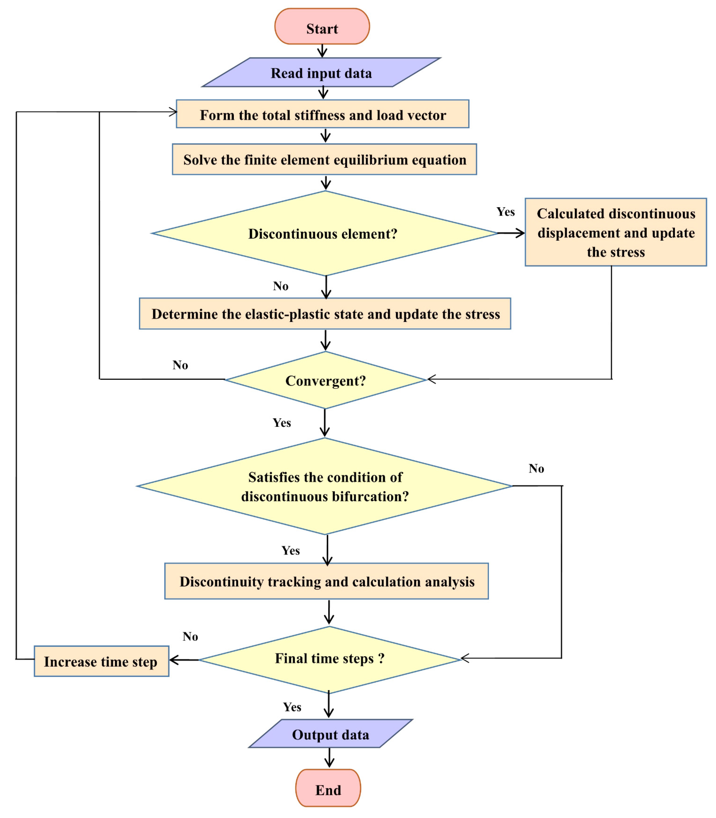
These studies highlight the important role of spectral analysis in evaluating the regularization mechanisms and numerical performance of various numerical methods for modeling localized failure in geomaterials. The implementation framework of spectral analysis in the finite element method is shown in Figure 12.
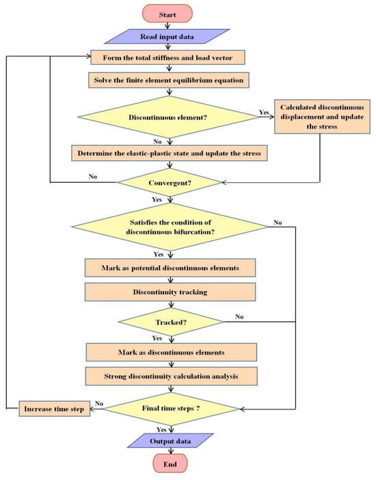
Figure 12.
Flowchart of the procedure of a spectral analysis of FEM.
5. Conclusions and Discussions
5.1. Conclusions
Strain localization is a fundamental and critical phenomenon in the failure mechanics of geotechnical materials, serving as a precursor to the instability and collapse of geotechnical structures. This review has systematically synthesized the theoretical, experimental, and numerical advancements in understanding and modeling strain localization.
From a theoretical perspective, classical geomechanics provides initial insights into the orientation of shear bands but falls short of predicting their initiation and evolution. Bifurcation theory offers a more rigorous mathematical framework for determining the onset conditions and directions of strain localization by treating it as a material instability problem where the governing equations lose ellipticity. However, its applicability is primarily limited to the pre-localization phase and does not capture the post-bifurcation behavior or the finite thickness of shear bands.
Experimental investigations have been instrumental in observing the characteristics of strain localization. Laboratory tests, including direct shear, conventional triaxial, plane strain, and true triaxial tests, have revealed the significant influences of factors such as particle size, shape, confining pressure, intermediate principal stress, and material anisotropy on the formation, inclination, and thickness of shear bands. Advanced measurement techniques like X-ray tomography and digital image correlation have provided unprecedented details into the internal microstructure evolution during localization. Nevertheless, challenges remain in replicating in situ stress conditions and capturing the full, complex three-dimensional nature of localization in experiments.
- (1)
- Numerical simulation has become an indispensable tool for studying strain localization. While the classical Finite Element Method (FEM) is powerful, it suffers from pathological mesh dependency when modeling strain softening due to the lack of an internal length scale. To address this, various regularization techniques have been developed.
- (2)
- Weak discontinuity methods, such as the Cosserat continuum theory, introduce an internal length scale (e.g., via rotational degrees of freedom and couple stresses), enabling the simulation of shear bands with finite thickness and obtaining mesh-independent results for materials exhibiting weak discontinuities.
- (3)
- Strong discontinuity methods, like the Strong Discontinuity Approach (SDA) and the (Extended Finite Element Method (XFEM), embed displacement jumps within elements. They are highly effective for modeling strong discontinuities (e.g., cracks) but typically assume zero-thickness localization zones, making them less suitable for materials where the finite thickness of shear bands plays a crucial role.
- (4)
- Innovative coupled methods, particularly the Cos-SDA model, represent a significant breakthrough. By integrating Cosserat continuum theory for the continuous phase and SDA for the discontinuity line, this approach successfully bridges the gap between weak and strong discontinuity modeling. It allows for the simulation of the entire progressive failure process—from diffuse strain localization (weak discontinuity) to the formation of distinct slip surfaces (strong discontinuity)—in semi-brittle geomaterials like soft rocks and cohesive–frictional soils.
Furthermore, spectral analysis has emerged as a powerful mathematical tool for evaluating the regularization performance and numerical stability of these advanced methods, providing deep insights into their underlying mechanisms.
5.2. Discussions and Future Perspectives
Despite considerable progress, several challenges and opportunities for future research remain:
- (1)
- From 2D to 3D Modeling: Many advanced numerical models, including the promising Cos-SDA framework, have been primarily developed and validated under 2D plane strain conditions. Extending these models to fully three-dimensional scenarios is crucial for tackling real-world geotechnical problems, such as the stability of tunnels, slopes, and foundations under complex loading conditions.
- (2)
- Model Validation and Parameter Determination: While numerical models are becoming increasingly sophisticated, determining their internal parameters (e.g., the internal length scale in Cosserat models) from standard laboratory tests remains challenging. There is a need for more comprehensive experimental data, particularly from true triaxial and hollow cylinder tests, to calibrate and validate these complex constitutive models under a wider range of stress paths.
- (3)
- Multi-Field Coupling: Although not covered in this review, it is important to note that multi-field coupling (e.g., hydro-mechanical, thermo-hydro-mechanical) has been successfully incorporated into strain localization models for porous media. Future work could further integrate such coupled processes into the advanced mechanical localization frameworks discussed herein, particularly for applications involving unsaturated soils, energy geostructures, or nuclear waste disposal.
- (4)
- Cyclic and Dynamic Loading: This review has primarily focused on monotonic loading conditions. However, many engineering applications involve cyclic (e.g., earthquake, wave) or dynamic loads. Investigating the evolution of strain localization under such loading conditions is an important and complex area for future research.
- (5)
- Transition to Large-Scale Engineering Applications: A key challenge lies in scaling up these advanced, often computationally intensive, models for analyzing large-scale geotechnical structures. Developing efficient computational strategies and simplified engineering models that retain the essential physics of localization will be vital for practical application.
- (6)
- Integration of Data-Driven Methods: The rise of artificial intelligence and machine learning offers new possibilities. These techniques could be used for model calibration, uncertainty quantification, and even developing surrogate models to accelerate simulations involving strain localization.
- (7)
- Advancement in Experimental and Multi-Scale Computational Techniques: Emerging technologies are revolutionizing the study of strain localization. The integration of X-ray computed tomography (X-ray CT) with Digital Image Correlation (DIC) provides unprecedented, four-dimensional insights into the evolution of internal microstructures and strain fields within geotechnical specimens during deformation. Concurrently, multi-scale coupling techniques, such as DEM-FEM coupling, bridge the gap between particle-scale mechanics and continuum-scale responses, offering a more fundamental understanding of localization initiation and propagation. Furthermore, Machine Learning (ML) and other data-driven approaches are opening new frontiers for constitutive model discovery, uncertainty quantification, and the development of efficient surrogate models, potentially bypassing traditional limitations of phenomenological modeling.
In conclusion, the field of strain localization in geotechnical materials has matured significantly, moving from fundamental theoretical concepts to sophisticated numerical tools capable of capturing complex continuous–discontinuous failure processes. The ongoing integration of theoretical insights, experimental observations, and computational power promises to further enhance our predictive capabilities, ultimately leading to safer and more efficient geotechnical designs.
Author Contributions
Writing—original draft preparation, Y.L.; writing—review and editing, Y.L.; investigation, A.S.; supervision, A.S.; validation, A.S., data curation, F.Z. All authors have read and agreed to the published version of the manuscript.
Funding
This research was funded by the Guizhou Provincial Basic Research Program (Natural Science) General Project (Qiankehe Foundation MS[2025]199), the Guizhou Institute of Technology Academic New Talent Cultivation and Innovative Exploration Project (2024XSXM013), the Guizhou Institute of Technology High-Caliber Talent Recruitment Program (2025GCC028), the Guizhou Province science and technology plan project (Qiankehe Platform KXJZ[2024]020), National Natural Science Foundation Project (52508370), Liaoning Province Natural Science Foundation Project (2025080377-JH3/101), Guizhou Province innovative high-level talent project (GCC[2023]053), and Guizhou Province innovative high-level. talent project (GCC[2023]091).
Institutional Review Board Statement
Not applicable.
Informed Consent Statement
Not applicable.
Data Availability Statement
The original contributions presented in this study are included in the article. Further inquiries can be directed to the corresponding author.
Conflicts of Interest
The authors declare no conflicts of interest.
References
- Kuhl, E.; Ramm, E.; Willam, K. Failure Analysis of Elasto-Plastic Material Models on Different Levels of Observation. Int. J. Solids Struct. 2000, 37, 7259–7280. [Google Scholar] [CrossRef]
- Mosler, J. Numerical Analyses of Discontinuous Material Bifurcation: Strong and Weak Discontinuities. Comput. Methods Appl. Mech. Eng. 2005, 194, 979–1000. [Google Scholar] [CrossRef]
- Oliver, J.; Cervera, M.; Manzoli, O. Strong Discontinuities and Continuum Plasticity Models: The Strong Discontinuity Approach. Int. J. Plast. 1999, 15, 319–351. [Google Scholar] [CrossRef]
- Arthur, J.R.F.; Dunstan, T.; Al-Ani, Q.A.J.L.; Assadi, A. Plastic Deformation and Failure in Granular Media. Geotechnique 1978, 28, 125–128. [Google Scholar] [CrossRef]
- Bardet, J.P. A Comprehensive Review of Strain Localization in Elastoplastic Soils. Comput. Geotech. 1990, 10, 163–188. [Google Scholar] [CrossRef]
- Euler, L. Methodus Inveniendi Lineas Curvas Maximi Minimive Proprietate Gaudentes, Sive Solutio Problematis Isoperimetrici Latissimo Sensu Accepti, Additamentum {II}; Marcum-Michaelem Bousquet: Lausanne, Switzerland, 1744. [Google Scholar]
- Poincaré, H. Sur l’équilibre d’une Masse Fluide Animée d’un Mouvement de Rotation. Acta Math. 1885, 7, 259–380. [Google Scholar] [CrossRef]
- Hadamard, J. Lecons Sur La Propagation Des Ondes et Les Equations de 1’hydrodynamicque; A. Hermann: Paris, France, 1903. [Google Scholar]
- Hill, R. A General Theory of Uniqueness and Stability in Elastic-Plastic Solids. J. Mech. Phys. Solids 1958, 6, 236–249. [Google Scholar] [CrossRef]
- Tracy, Y.T. Plastic Flow and Fracture in Solids; Elsevier: Amsterdam, The Netherlands, 1961. [Google Scholar]
- Hill, R. Acceleration Waves in Solids. J. Mech. Phys. Solids 1962, 10, 1–16. [Google Scholar] [CrossRef]
- Mandel, J. Conditions de Stabilité et Postulat de Drucker; Springer: Berlin/Heidelberg, Germany, 1966. [Google Scholar]
- Rice, J.R. The Localization of Plastic Deformation. In Proceedings of the 14th International Congress of Theoratical Applied Mechanics, Delf, The Netherlands, 30 August–4 September 1976; pp. 207–220. [Google Scholar]
- Rudnicki, J.W.; Rice, J.R. Conditions for the Localization of Deformation in Pressure-Sensitive Dilatant Materials. J. Mech. Phys. Solids 1975, 23, 371–394. [Google Scholar] [CrossRef]
- Runesson, K.; Saabye Ottosen, N.; Dunja, P. Discontinuous Bifurcations of Elastic-Plastic Solutions at Plane Stress and Plane Strain. Int. J. Plast. 1991, 7, 99–121. [Google Scholar] [CrossRef]
- Ottosen, N.S.; Runesson, K. Properties of Discontinuous Bifurcation Solutions in Elasto-Plasticity. Int. J. Solids Struct. 1991, 27, 401–421. [Google Scholar] [CrossRef]
- Mechanics, E. Bifurcations in Elastic-Plastic. Int. J. Solids Struct. 1993, 30, 521–544. [Google Scholar]
- De Borst, R.; Sluys, L.J.; Mühlhaus, H.B.; Pamin, J. Fundamental Issues in Finite Element Analyses of Localization of Deformation. Eng. Comput. 1993, 10, 99–121. [Google Scholar] [CrossRef]
- Tomita, Y. Simulations of Plastic Instabilities in Solid Mechanics. Appl. Mech. Rev. 1994, 47, 171–205. [Google Scholar] [CrossRef]
- Drucker, D.C. On Uniqueness in the Theory of Plasticity. Q. Appl. Math. 1956, 14, 35–42. [Google Scholar] [CrossRef]
- Valanis, K.C. Banding and Stability in Plastic Materials. Acta Mech. 1989, 79, 113–141. [Google Scholar] [CrossRef]
- Morgenstern, N.R.; Tchalenko, J. S Microscopic Structures in Kaolin Subjected to Direct Shear. Géotechnique 1967, 17, 309–328. [Google Scholar] [CrossRef]
- Roscoe, K.H. The Influence of Strains in Soil Mechanics. Geotechnique 1970, 20, 129–170. [Google Scholar] [CrossRef]
- Scarpelli, G.; Wood, D.M. Experimental Observation of Shear Band Pattern in Direct Shear Tests. In Proceedings of the IUTAM: Conference on Deformation and Failure of Granular Materials, Delft, The Netherlands, 31 August–3 September 1982. [Google Scholar]
- Bishop, A.W.; Henkel, D.J. The Measurement of Soil Properties in the Triaxial Test; E. Arnold: London, UK, 1957. [Google Scholar]
- Arthur, J.R.F.; Dunstan, T. Rupture Layers in Granular Media. Deform. Fail. Granul. Mater. IUTAM Symp. Delft 1982.
- Lade, P.V.; Tsai, J. Effects of Localization in Triaxial Tests on Clay. In Proceedings of the 11th International Conference on Soil Mechanics and Foundation Engineering, San Francisco, CA, USA, 12–16 August 1985. [Google Scholar]
- Vardoulakis, I. Bifurcation Analysis of the Triaxial Test on Sand Samples. Acta Mech. 1979, 32, 35–54. [Google Scholar] [CrossRef]
- Hettler, A.; Vardoulakis, I. Behaviour of Dry Sand Tested in a Large Triaxial Apparatus. Geotechnique 1984, 34, 183–197. [Google Scholar] [CrossRef]
- Desrues, J.; Chambon, R.; Mokni, M.; Mazerolle, F. Void Ratio Evolution inside Shear Bands in Triaxial Sand Specimens Studied by Computed Tomography. Geotechnique 1996, 46, 529–546. [Google Scholar] [CrossRef]
- Alshibli, K.A.; Batiste, S.N.; Sture, S. Strain Localization in Sand: Plane Strain versus Triaxial Compression. J. Geotech. Geoenvironmental Eng. 2003, 129, 483–494. [Google Scholar] [CrossRef]
- Meng, L.; Li, T.; Jiang, L.; Ma, H. Experimental Study on the Influence of Temperature on Shale Mechanical Properties under Conventional Triaxial Compression. Adv. Mater. Res. 2011, 250–253, 1452–1455. [Google Scholar] [CrossRef]
- Vardoulakis, I. Shear Band Inclination and Shear Modulus of Sand in Biaxial Tests. Int. J. Numer. Anal. Methods Geomech. 1980, 4, 103–119. [Google Scholar] [CrossRef]
- Vardoulakis, I.; Graf, B. Calibration of Constitutive Models for Granular Materials Using Data from Biaxial Experiments. Geotechnique 1985, 35, 299–317. [Google Scholar] [CrossRef]
- Vermeer, P.A. The Orientation of Shear Bands in Biaxial Tests. Geotechnique 1990, 40, 223–236. [Google Scholar] [CrossRef]
- Han, C.; Vardoulakis, I.G. Plane-Strain Compression Experiments on Water-Saturated Fine-Grained Sand. Geotechnique 1991, 41, 49–78. [Google Scholar] [CrossRef]
- Han, C.; Drescher, A. Shear Bands in Biaxial Tests on Dry Coarse Sand. Soils Found. 1993, 33, 118–132. [Google Scholar] [CrossRef]
- Labuz, J.F.; Dai, S.T.; Papamichos, E. Plane-Strain Compression of Rock-like Materials. Int. J. Rock Mech. Min. Sci. Geomech. 1996, 33, 573–584. [Google Scholar] [CrossRef]
- Finno, R.J.; Harris, W.W.; Mooney, M.A.; Viggiani, G. Shear Bands in Plane Strain Compression of Loose Sand. Geotechnique 1997, 47, 149–165. [Google Scholar] [CrossRef]
- Alshibli, K.A.; Sture, S. Shear Band Formation in Plane Strain Experiments of Sand. J. Geotech. Geoenvironmental Eng. 2000, 126, 20000069798. [Google Scholar] [CrossRef]
- Chu, J.; Lo, S.C.R.; Lee, I.K. Strain Softening and Shear Band Formation of Sand in Multi-Axial Testing. Geotechnique 1996, 46, 63–82. [Google Scholar] [CrossRef]
- Wang, Q.; Lade, P.V. Shear Banding in True Triaxial Tests and Its Effect on Failure in Sand. J. Eng. Mech. 2001, 127, 754–761. [Google Scholar] [CrossRef]
- Rodriguez, N.M.; Lade, P.V. True Triaxial Tests on Cross-Anisotropic Deposits of Fine Nevada Sand. Int. J. Geomech. 2013, 13, 779–793. [Google Scholar] [CrossRef]
- Minaeian, V.; Dewhurst, D.N.; Rasouli, V. An Investigation on Failure Behaviour of a Porous Sandstone Using Single-Stage and Multi-Stage True Triaxial Stress Tests. Rock Mech. Rock Eng. 2020, 53, 3543–3562. [Google Scholar] [CrossRef]
- Dimitri, R.; Rinaldi, M.; Trullo, M.; Tornabene, F.; Fidelibus, C. FEM/XFEM Modeling of the 3D Fracturing Process in Transversely Isotropic Geomaterials. Compos. Struct. 2021, 276, 114502. [Google Scholar] [CrossRef]
- Trädegård, A.; Nilsson, F.; Östlund, S. FEM-Remeshing Technique Applied to Crack Growth Problems. Comput. Methods Appl. Mech. Eng. 1998, 160, 115–131. [Google Scholar] [CrossRef]
- Bordas, S.P.A.; Rabczuk, T.; Hung, N.X.; Nguyen, V.P.; Natarajan, S.; Bog, T.; Quan, D.M.; Hiep, N.V. Strain Smoothing in FEM and XFEM. Comput. Struct. 2010, 88, 1419–1443. [Google Scholar] [CrossRef]
- Anderssohn, R.; Hofmann, M.; Bahr, H.A. FEM-Bifurcation Analysis for 3D Crack Patterns. Eng. Fract. Mech. 2018, 202, 363–374. [Google Scholar] [CrossRef]
- Lambert, C.; Buzzi, O.; Giacomini, A. Influence of Calcium Leaching on the Mechanical Behavior of a Rock-Mortar Interface: A DEM Analysis. Comput. Geotech. 2010, 37, 258–266. [Google Scholar] [CrossRef]
- Wang, R.; Dafalias, Y.F.; Fu, P.; Zhang, J.M. Fabric Evolution and Dilatancy within Anisotropic Critical State Theory Guided and Validated by DEM. Int. J. Solids Struct. 2020, 188–189, 210–222. [Google Scholar] [CrossRef]
- Schöpfer, M.P.J.; Abe, S.; Childs, C.; Walsh, J.J. The Impact of Porosity and Crack Density on the Elasticity, Strength and Friction of Cohesive Granular Materials: Insights from DEM Modelling. Int. J. Rock Mech. Min. Sci. 2009, 46, 250–261. [Google Scholar] [CrossRef]
- Mendonça, T.S.; Peixoto, R.G.; Ribeiro, G.O. Crack Propagation Using the Continuum Strong Discontinuity Approach by the BEM: Some Numerical Remarks. J. Brazilian Soc. Mech. Sci. Eng. 2018, 40, 520. [Google Scholar] [CrossRef]
- Giannopoulos, G.I.; Anifantis, N.K. A BEM Analysis for Thermomechanical Closure of Interfacial Cracks Incorporating Friction and Thermal Resistance. Comput. Methods Appl. Mech. Eng. 2007, 196, 1018–1029. [Google Scholar] [CrossRef]
- Peixoto, R.G.; Ribeiro, G.O.; Pitangueira, R.L.S.; Penna, S.S. The Strong Discontinuity Approach as a Limit Case of Strain Localization in the Implicit BEM Formulation. Eng. Anal. Bound. Elem. 2017, 80, 127–141. [Google Scholar] [CrossRef]
- Panique Lazcano, D.R.; Galindo Aires, R.; Patiño Nieto, H. Bearing Capacity of Shallow Foundation under Cyclic Load on Cohesive Soil. Comput. Geotech. 2020, 123, 103556. [Google Scholar] [CrossRef]
- Zhang, J.; Li, L.; Sun, D. Similarity Solution for Undrained Cylindrical Cavity Contraction in Anisotropic Modified Cam-Clay Model Soils. Comput. Geotech. 2020, 120, 103405. [Google Scholar] [CrossRef]
- Yan, L.; Xu, W.; Wang, R.; Meng, Q. Numerical Simulation of the Anisotropic Properties of a Columnar Jointed Rock Mass under Triaxial Compression. Eng. Comput. 2018, 35, 1788–1804. [Google Scholar] [CrossRef]
- Menon, S.; Song, X. A Computational Periporomechanics Model for Localized Failure in Unsaturated Porous Media. Comput. Methods Appl. Mech. Eng. 2021, 384, 113932. [Google Scholar] [CrossRef]
- Tao, S.; Tang, X.; Rutqvist, J.; Hu, M.; Liu, Q. Simulating Three Dimensional Thermal Cracking with TOUGH-FEMM. Comput. Geotech. 2020, 124, 103654. [Google Scholar] [CrossRef]
- Li, S.; Liu, W.K. Meshfree and Particle Methods and Their Applications. Appl. Mech. Rev. 2002, 55, 1–34. [Google Scholar] [CrossRef]
- Lu, M.; Zhang, H.; Zheng, Y.; Zhang, L. A Multiscale Finite Element Method with Embedded Strong Discontinuity Model for the Simulation of Cohesive Cracks in Solids. Comput. Methods Appl. Mech. Eng. 2016, 311, 576–598. [Google Scholar] [CrossRef]
- Andrade, J.E.; Avila, C.F. Multiscale Modeling of Granular Matter: A Hierarchical Scheme. In Multiscale and Multiphysics Processes in Geomechanics, Borja, R.I., Ed.; Springer: Berlin/Heidelberg, Germany, 2011; ISBN 9783642196294. [Google Scholar]
- Chen, Q.; Andrade, J.E.; Samaniego, E. AES for Multiscale Localization Modeling in Granular Media. Comput. Methods Appl. Mech. Eng. 2011, 200, 2473–2482. [Google Scholar] [CrossRef]
- Sun, Y.; Roubin, E.; Shao, J.; Colliat, J.B. FE Modeling of Concrete with Strong Discontinuities for 3D Shear Fractures and Comparison with Experimental Results. Eng. Fract. Mech. 2021, 251, 107752. [Google Scholar] [CrossRef]
- Tang, H.; Dong, Y.; Wang, T.; Dong, Y. Simulation of strain localization with discrete element-Cosserat continuum finite element two scale method for granular materials. J. Mech. Phys. Solids 2019, 122, 450–471. [Google Scholar] [CrossRef]
- Arslan, H.; Sture, S. Finite Element Simulation of Localization in Granular Materials by Micropolar Continuum Approach. Comput. Geotech. 2008, 35, 548–562. [Google Scholar] [CrossRef]
- Radulovic, R. Numerical Modeling of Localized Material Failure by Means of Strong Discontinuities at Finite Strains. Ph.D. Thesis, Ruhr University Bochum, Bochum, Germany, 2010. [Google Scholar]
- Wei, W.; Tang, H.; Liu, Y.; Chen, H. Cosserat model incorporating anisotropy evolution and its application in numerical analysis of strain localization in clay. Acta Geotech. 2025, 20, 365–385. [Google Scholar] [CrossRef]
- Ebrahimian, B. Evolution of Shear Localization in an Elasto-Plastic Cosserat Material under Shearing. Key Eng. Mater. 2014, 577–578, 21–24. [Google Scholar] [CrossRef]
- de Borst, R. A Generalisation of J2-Flow Theory for Polar Continua. Comput. Methods Appl. Mech. Eng. 1993, 103, 347–362. [Google Scholar] [CrossRef]
- Iordache, M.M.; Willam, K. Localized Failure Analysis in Elastoplastic Cosserat Continua. Comput. Methods Appl. Mech. Eng. 1998, 151, 559–586. [Google Scholar] [CrossRef]
- De Borst, R. Simulation of Strain Localization: A Reappraisal of the Cosserat Continuum. Eng. Comput. 1991, 8, 317–332. [Google Scholar] [CrossRef]
- Chen, J.S.; Zhang, X.; Belytschko, T. An Implicit Gradient Model by a Reproducing Kernel Strain Regularization in Strain Localization Problems. Comput. Methods Appl. Mech. Eng. 2004, 193, 2827–2844. [Google Scholar] [CrossRef]
- Tvergaard, V.; Needleman, A. Effects of Nonlocal Damage in Porous Plastic Solids. Int. J. Solids Struct. 1995, 32, 1063–1077. [Google Scholar] [CrossRef]
- Lu, X.; Bardet, J.P.; Huang, M. Numerical Solutions of Strain Localization with Nonlocal Softening Plasticity. Comput. Methods Appl. Mech. Eng. 2009, 198, 3702–3711. [Google Scholar] [CrossRef]
- Mánica, M.A.; Gens, A.; Vaunat, J.; Ruiz, D.F. Nonlocal Plasticity Modelling of Strain Localisation in Stiff Clays. Comput. Geotech. 2018, 103, 138–150. [Google Scholar] [CrossRef]
- Eringen, A.C.; Edelen, D.G.B. On Nonlocal Elasticity. Int. J. Eng. Sci. 1972, 10, 233–248. [Google Scholar] [CrossRef]
- Zervos, A.; Papanastasiou, P.; Vardoulakis, I. A Finite Element Displacement Formulation for Gradient Elastoplasticity. Int. J. Numer. Methods Eng. 2001, 50, 1369–1388. [Google Scholar] [CrossRef]
- Zervos, A.; Papanastasiou, P.; Vardoulakis, I. Shear Localisation in Thick-Walled Cylinders Under Internal Pressure Based on Gradient. J. Theor. Appl. Mech. 2008, 38, 81–100. [Google Scholar]
- De Borst, R.; Mühlhaus, H.-B. Gradient-dependent Plasticity: Formulation and Algorithmic Aspects. Int. J. Numer. Methods Eng. 1992, 35, 521–539. [Google Scholar] [CrossRef]
- Chiricotto, M.; Giacomelli, L.; Tomassetti, G. Dissipative Scale Effects in Strain-Gradient Plasticity: The Case of Simple Shear. SIAM J. Appl. Math. 2016, 76, 688–704. [Google Scholar] [CrossRef]
- Zervos, A.; Vardoulakis, I.; Papanastasiou, P. Influence of Nonassociativity on Localization and Failure in Geomechanics Based on Gradient Elastoplasticity. Int. J. Geomech. 2007, 7, 63–74. [Google Scholar] [CrossRef]
- Niazi, M.S.; Wisselink, H.H.; Meinders, T. Viscoplastic Regularization of Local Damage Models: A Latent Solution. Key Eng. Mater. 2012, 504–506, 845–850. [Google Scholar] [CrossRef]
- Simons, E.C.; Weerheijm, J.; Sluys, L.J. A Viscosity Regularized Plasticity Model for Ceramics. Eur. J. Mech. A/Solids 2018, 72, 310–328. [Google Scholar] [CrossRef]
- Cosserat, E.; Cosserat, F. Théorie Des Corps Déformables; Herman et Fils: Paris, France, 1909. [Google Scholar]
- Mindlin, R.D. Influence of Couple-Stresses on Stress Concentrations. Exp. Mech. 1963, 3, 1–7. [Google Scholar] [CrossRef]
- Sternberg, E.; Muki, R. The Effect of Couple-Stresses on the Stress Concentration around a Crack. Int. J. Solids Struct. 1967, 3, 69–95. [Google Scholar] [CrossRef]
- Mühlhaus, H.B.; Vardoulakis, I. The Thickness of Shear Bands in Granular Materials. Geotechnique 1987, 37, 271–283. [Google Scholar] [CrossRef]
- Papanastasiou, P.C.; Vardoulakis, I.G. Numerical Treatment of Progressive Localization in Relation to Borehole Stability. Int. J. Numer. Anal. Methods Geomech. 1992, 16, 389–424. [Google Scholar] [CrossRef]
- Oda, M.; Iwashita, K.; Kazama, H. Micro-Structure Developed in Shear Bands of Dense Granular Soils and Its Computer Simulation—Mechanism of Dilatancy and Failure. In IUTAM Symposium on Mechanics of Granular and Porous Materials; Solid Mechanics and its Applications; Fleck, N.A., Cocks, A.C.F., Eds.; Springer: Dordrecht, The Netherlands, 1997. [Google Scholar]
- Papanastasiou, P.; Zervos, A. Wellbore Stability Analysis: From Linear Elasticity to Postbifurcation Modeling. Int. J. Geomech. 2004, 4, 2–12. [Google Scholar] [CrossRef]
- Khoei, A.R.; Karimi, K. An Enriched-FEM Model for Simulation of Localization Phenomenon in Cosserat Continuum Theory. Comput. Mater. Sci. 2008, 44, 733–749. [Google Scholar] [CrossRef]
- Li, X.; Tang, H. A Consistent Return Mapping Algorithm for Pressure-Dependent Elastoplastic Cosserat Continua and Modelling of Strain Localisation. Comput. Struct. 2005, 83, 1–10. [Google Scholar] [CrossRef]
- Zhang, H.W.; Wang, H.; Chen, B.S.; Xie, Z.Q. Analysis of Cosserat Materials with Voronoi Cell Finite Element Method and Parametric Variational Principle. Comput. Methods Appl. Mech. Eng. 2008, 197, 741–755. [Google Scholar] [CrossRef]
- Chen, K.; Zou, D.; Tang, H.; Liu, J.; Zhuo, Y. Scaled Boundary Polygon Formula for Cosserat Continuum and Its Verification. Eng. Anal. Bound. Elem. 2021, 126, 136–150. [Google Scholar] [CrossRef]
- Tang, H.; Guan, Y.; Zhang, X.; Zou, D. Low-Order Mixed Finite Element Analysis of Progressive Failure in Pressure-Dependent Materials within the Framework of the Cosserat Continuum. Eng. Comput. 2017, 34, 251–271. [Google Scholar] [CrossRef]
- Tang, H.; Zhu, F.; Yang, D.; Papazafeiropoulos, G. Numerical Simulation of Strain Localization Based on Cosserat Continuum Theory and Isogeometric Analysis. Comput. Geotech. 2021, 129, 103874. [Google Scholar] [CrossRef]
- Tang, H.; Wei, W.; Liu, F.; Chen, G. Elastoplastic Cosserat Continuum Model Considering Strength Anisotropy and Its Application to the Analysis of Slope Stability. Comput. Geotech. 2020, 117, 103235. [Google Scholar] [CrossRef]
- Tang, H.; Sun, F.; Zhang, Y.; Dong, Y. Elastoplastic Axisymmetric Cosserat Continua and Modelling of Strain Localization. Comput. Geotech. 2018, 101, 159–167. [Google Scholar] [CrossRef]
- Jirásek, M.; Zimmermann, T. Rotating Crack Model with Transition to Scalar Damage. J. Eng. Mech. 1998, 124, 277–284. [Google Scholar] [CrossRef]
- Jirásek, M.; Zimmermann, T. Analysis of Rotating Crack Model. J. Eng. Mech. 1998, 124, 842–851. [Google Scholar] [CrossRef]
- Tejchman, J.; Bauer, E. Numerical Simulation of Shear Band Formation with a Polar Hypoplastic Constitutive Model. Comput. Geotech. 1996, 19, 221–244. [Google Scholar] [CrossRef]
- Xie, D.; Waas, A.M. Discrete Cohesive Zone Model for Mixed-Mode Fracture Using Finite Element Analysis. Eng. Fract. Mech. 2006, 73, 1783–1796. [Google Scholar] [CrossRef]
- Aymerich, F.; Dore, F.; Priolo, P. Prediction of Impact-Induced Delamination in Cross-Ply Composite Laminates Using Cohesive Interface Elements. Compos. Sci. Technol. 2008, 68, 2383–2390. [Google Scholar] [CrossRef]
- Turon, A.; Dávila, C.G.; Camanho, P.P.; Costa, J. An Engineering Solution for Mesh Size Effects in the Simulation of Delamination Using Cohesive Zone Models. Eng. Fract. Mech. 2007, 74, 1665–1682. [Google Scholar] [CrossRef]
- Nguyen, V.P.; Nguyen, C.T.; Bordas, S.; Heidarpour, A. Modelling Interfacial Cracking with Non-Matching Cohesive Interface Elements. Comput. Mech. 2016, 58, 731–746. [Google Scholar] [CrossRef]
- Kawashita, L.F.; Hallett, S.R. A Crack Tip Tracking Algorithm for Cohesive Interface Element Analysis of Fatigue Delamination Propagation in Composite Materials. Int. J. Solids Struct. 2012, 49, 2898–2913. [Google Scholar] [CrossRef]
- Paulino, G.H.; Celes, W.; Espinha, R.; Zhang, Z.J. A General Topology-Based Framework for Adaptive Insertion of Cohesive Elements in Finite Element Meshes. Eng. Comput. 2008, 24, 59–78. [Google Scholar] [CrossRef]
- Samimi, M.; Van Dommelen, J.A.W.; Geers, M.G.D. A Self-Adaptive Finite Element Approach for Simulation of Mixed-Mode Delamination Using Cohesive Zone Models. Eng. Fract. Mech. 2011, 78, 2202–2219. [Google Scholar] [CrossRef]
- Schrefler, B.A.; Secchi, S.; Simoni, L. On Adaptive Refinement Techniques in Multi-Field Problems Including Cohesive Fracture. Comput. Methods Appl. Mech. Eng. 2006, 195, 444–461. [Google Scholar] [CrossRef]
- Armero, F.; Garikipati, K. An Analysis of Strong Discontinuities in Multiplicative Finite Strain Plasticity and Their Relation with the Numerical Simulation of Strain Localization in Solids. Int. J. Solids Struct. 1996, 33, 2863–2885. [Google Scholar] [CrossRef]
- Oliver, J. Modelling Strong Discontinuities in Solid Mechanics via Strain Softening Constitutive Equations. Part 1: Fundamentals. Int. J. Numer. Methods Eng. 1996, 39, 3575–3600. [Google Scholar] [CrossRef]
- Fan, Z.; Zheng, H.; Nie, Z.; Wang, Y.; Han, C. Influence of Soil Non-Homogeneity on Shear Band Evolution Investigated by the Numerical Manifold Method Combined with the Assumed Enhanced Strain Method. Eng. Anal. Bound. Elem. 2021, 127, 1–7. [Google Scholar] [CrossRef]
- Borja, R.I. Finite Element Model for Strain Localization Analysis of Strongly Discontinuous Fields Based on Standard Galerkin Approximation. Comput. Methods Appl. Mech. Eng. 2000, 190, 1529–1549. [Google Scholar] [CrossRef]
- Simo, J.C.; Oliver, J.; Armero, F. An Analysis of Strong Discontinuities Induced by Strain-Softening in Rate-Independent Inelastic Solids. Comput. Mech. 1993, 12, 277–296. [Google Scholar] [CrossRef]
- Nagashima, T.; Wang, C. XFEM Analyses Using Two-Dimensional Quadrilateral Elements Enriched with Only the Heaviside Step Function. Int. J. Comput. Methods 2022, 19, 2150063. [Google Scholar] [CrossRef]
- Belytschko, T.; Moës, N.; Usui, S.; Parimi, C. Arbitrary Discontinuities in Finite Elements. Int. J. Numer. Methods Eng. 2001, 50, 993–1013. [Google Scholar] [CrossRef]
- Belytschko, T.; Black, T. Elastic Crack Growth in Finite Elements with Minimal Remeshing. Int. J. Numer. Methods Eng. 1999, 45, 601–620. [Google Scholar] [CrossRef]
- Liu, Z.L.; Menouillard, T.; Belytschko, T. An XFEM/Spectral Element Method for Dynamic Crack Propagation. Int. J. Fract. 2011, 169, 183–198. [Google Scholar] [CrossRef]
- Oliver, J.; Huespe, A.E.; Sánchez, P.J. A Comparative Study on Finite Elements for Capturing Strong Discontinuities: E-FEM vs X-FEM. Comput. Methods Appl. Mech. Eng. 2006, 195, 4732–4752. [Google Scholar] [CrossRef]
- Dvorkin, E.N.; Cuitiño, A.M.; Gioia, G. Finite Elements with Displacement Interpolated Embedded Localization Lines Insensitive to Mesh Size and Distortions. Int. J. Numer. Methods Eng. 1990, 30, 541–564. [Google Scholar] [CrossRef]
- Klisinski, M.; Runesson, K.; Sture, S. Finite Element with Inner Softening Band. J. Eng. Mech. 1991, 117, 575–587. [Google Scholar] [CrossRef]
- Reza, H. Finite Element Analysis of Fracture of Concrete and Masonry Structures. Ph.D. Thesis, University of Colorado, Boulder, CO, USA, 1992. [Google Scholar]
- Oliver, J. Modelling Strong Discontinuities in Solid: Part 2. Int. J. Numer. Method Eng. 1996, 39, 3601–3623. [Google Scholar] [CrossRef]
- Regueiro, R.A.; Borja, R.I. Plane Strain Finite Element Analysis of Pressure Sensitive Plasticity with Strong Discontinuity. Int. J. Solids Struct. 2001, 38, 3647–3672. [Google Scholar] [CrossRef]
- Regueiro, R.A.; Borja, R.I. A Finite Element Model of Localized Deformation in Frictional Materials Taking a Strong Discontinuity Approach. Finite Elem. Anal. Des. 1999, 33, 283–315. [Google Scholar] [CrossRef]
- Oliver, J.; Huespe, A.E.; Pulido, M.D.G.; Chaves, E. From Continuum Mechanics to Fracture Mechanics: The Strong Discontinuity Approach. Eng. Fract. Mech. 2001, 69, 113–136. [Google Scholar] [CrossRef]
- Armero, F.; Ehrlich, D. Finite Element Methods for the Multi-Scale Modeling of Softening Hinge Lines in Plates at Failure. Comput. Methods Appl. Mech. Eng. 2006, 195, 1283–1324. [Google Scholar] [CrossRef]
- Ehrlich, D.; Armero, F. Finite Element Methods for the Analysis of Softening Plastic Hinges in Beams and Frames. Comput. Mech. 2005, 35, 237–264. [Google Scholar] [CrossRef]
- Alfaiate, J.; Moonen, P.; Sluys, L.J.; Carmeliet, J. On the Use of Strong Discontinuity Formulations for the Modeling of Preferential Moisture Uptake in Fractured Porous Media. Comput. Methods Appl. Mech. Eng. 2010, 199, 2828–2839. [Google Scholar] [CrossRef]
- Foster, C.D.; Borja, R.I.; Regueiro, R.A. Embedded Strong Discontinuity Finite Elements for Fractured Geomaterials with Variable Friction. Int. J. Numer. Meth. Eng. 2007, 72, 549–581. [Google Scholar] [CrossRef]
- Lu, M.; Zhang, H.; Zheng, Y.; Zhang, L. A Multiscale Finite Element Method for the Localization Analysis of Homogeneous and Heterogeneous Saturated Porous Media with Embedded Strong Discontinuity Model. Int. J. Numer. Methods Eng. 2017, 112, 1439–1472. [Google Scholar] [CrossRef]
- Benkemoun, N.; Gelet, R.; Roubin, E.; Colliat, J.B. Poroelastic Two-Phase Material Modeling: Theoretical Formulation and Embedded Finite Element Method Implementation. Int. J. Numer. Anal. Methods Geomech. 2015, 39, 1255–1275. [Google Scholar] [CrossRef]
- Čarija, J.; Nikolić, M.; Ibrahimbegovic, A.; Nikolić, Ž. Discrete Softening-Damage Model for Fracture Process Representation with Embedded Strong Discontinuities. Eng. Fract. Mech. 2020, 236, 107211. [Google Scholar] [CrossRef]
- Fagerström, M.; Larsson, R. Theory and Numerics for Finite Deformation Fracture Modelling Using Strong Discontinuities. Int. J. Numer. Methods Eng. 2006, 66, 911–948. [Google Scholar] [CrossRef]
- Alfaiate, J.; Simone, A.; Sluys, L.J. Non-Homogeneous Displacement Jumps in Strong Embedded Discontinuities. Int. J. Solids Struct. 2003, 40, 5799–5817. [Google Scholar] [CrossRef]
- Motamedi, M.H.; Weed, D.A.; Foster, C.D. Numerical Simulation of Mixed Mode (I and II) Fracture Behavior of Pre-Cracked Rock Using the Strong Discontinuity Approach. Int. J. Solids Struct. 2016, 85–86, 44–56. [Google Scholar] [CrossRef]
- Hadzalic, E.; Ibrahimbegovic, A.; Dolarevic, S. Failure Mechanisms in Coupled Soil-Foundation Systems. Coupled Syst. Mech. 2018, 7, 27–42. [Google Scholar] [CrossRef]
- Nikolic, M.; Ibrahimbegovic, A. Rock Mechanics Model Capable of Representing Initial Heterogeneities and Full Set of 3D Failure Mechanisms. Comput. Methods Appl. Mech. Eng. 2015, 290, 209–227. [Google Scholar] [CrossRef]
- Tang, H.; Li, Y.; Hu, Z.; Song, X. Numerical Simulation of Strain Localization through an Integrated Cosserat Continuum Theory and Strong Discontinuity Approach. Comput. Geotech. 2022, 151, 104951. [Google Scholar] [CrossRef]
- Li, Y.; Tang, H.; Song, X.; Hu, Z. Regularization Analysis of the Strong Discontinuity-Cosserat Finite Element Method for Modeling Strain Localization in Cohesive-Frictional Materials by Spectral Theory. Comput. Geotech. 2023, 162, 105640. [Google Scholar] [CrossRef]
- Li, Y.; Tang, H.; Zhu, F.; Hu, Z. An Anisotropic Elastoplastic Strong Discontinuity Model for Shear Failure in Anisotropic Rock Masses. Comput. Geotech. 2024, 176, 106762. [Google Scholar] [CrossRef]
- Borja, R.I.; Regueiro, R.A. Strain Localization in Frictional Materials Exhibiting Displacement Jumps. Comput. Methods Appl. Mech. Eng. 2001, 190, 2555–2580. [Google Scholar] [CrossRef]
- Di Luzio, G. Spectral Localization Analysis in Nonlocal Softening Materials. In Proceedings of the 9th International Conference on Fracture Mechanics of Concrete and Concrete Structures (FraMCoS-9), Berkeley, CA, USA, 29 May–1 June 2016. [Google Scholar] [CrossRef]
- Bardet, J.P. Finite Element Analysis of Rockburst as Surface Instability. Comput. Geotech. 1989, 8, 177–193. [Google Scholar] [CrossRef]
- Bardet, J.P. Finite Element Analysis of Plane Strain Bifurcation within Compressible Solids. Comput. Struct. 1990, 36, 993–1007. [Google Scholar] [CrossRef]
- Bathe, K.J. Finite Element Procedures; Stenquist, W., Ed.; Prentice Hall: New Jersey, NJ, USA, 1996; ISBN 0133014584. [Google Scholar]
- Van der Veen, H.; Vuik, C.; De Borst, R. Eigenvalue Analysis of Nonassociated Plasticity. Comput. Math. Appl. 1999, 38, 107–115. [Google Scholar] [CrossRef]
- Di Luzio, G.; Bažant, Z.P. Spectral Analysis of Localization in Nonlocal and Over-Nonlocal Materials with Softening Plasticity or Damage. Int. J. Solids Struct. 2005, 42, 6071–6100. [Google Scholar] [CrossRef]
- Lu, X.; Bardet, J.P.; Huang, M. Spectral Analysis of Nonlocal Regularization in Two-Dimensional Finite Element Models. Int. J. Numer. Anal. Methods Geomech. 2012, 36, 219–235. [Google Scholar] [CrossRef]
Disclaimer/Publisher’s Note: The statements, opinions and data contained in all publications are solely those of the individual author(s) and contributor(s) and not of MDPI and/or the editor(s). MDPI and/or the editor(s) disclaim responsibility for any injury to people or property resulting from any ideas, methods, instructions or products referred to in the content. |
© 2025 by the authors. Licensee MDPI, Basel, Switzerland. This article is an open access article distributed under the terms and conditions of the Creative Commons Attribution (CC BY) license (https://creativecommons.org/licenses/by/4.0/).

