Article

Influence of Ground Conditions on Vibration Propagation and Response Under Accidental Impact Loads

1
Department of Fire & Emergency Management, Kangwon National University, 346 Hwangjo-gil, Dogye-eup, Samcheok-si 25949, Republic of Korea
2
Department of Civil and Environmental Engineering, Hanyang University, 222 Wangsimni-ro, Seongdong-gu, Seoul 04763, Republic of Korea
3
Safety Innovation & Disaster Prevention Research Division, Korea Expressway Corporation Research Institute, 24 Dongtan Sunhwan-ro 17-gil, Dongtan-myeon, Hwaseong-si 18489, Republic of Korea
4
Department of Civil & Environmental Engineering, Gachon University, 1342 Seongnam-daero, Sujeong-gu, Seongnam-si 13120, Republic of Korea
5
Department of Civil Engineering, Kangwon National University, 346, Jungang-ro, Samcheok-si 25913, Republic of Korea
6
Department Civil Engineering, Kumoh National Institute of Technology, 61 Daehak-ro, Gumi 39177, Republic of Korea
*
Author to whom correspondence should be addressed.
Appl. Sci. 2025, 15(22), 12068; https://doi.org/10.3390/app152212068
Submission received: 27 October 2025 / Revised: 8 November 2025 / Accepted: 10 November 2025 / Published: 13 November 2025
(This article belongs to the Special Issue Soil Dynamics and Earthquake Engineering)

Abstract

Vibrations of unknown origin can cause fear and confusion when their sources are unrecognized. In modern construction environments, such vibrations may result not only from earthquakes but also from accidental impacts during industrial operations. However, due to the absence of established safety standards, evaluating and compensating for the effects of short-duration, high-intensity vibrations has remained difficult. This study investigates the characteristics of ground motions induced by accidental impact loads through finite element-based numerical simulations. The analyses identify key factors that control vibration propagation under various subsurface conditions. The results show that an impact load produces a single impulsive motion dominated by a vertical component, which decays exponentially with time. The amplitude of vibration increases with drop height and girder mass, confirming the relationship between potential energy and vibration intensity. The attenuation of peak particle velocity (PPV) follows a logarithmic pattern with distance, and the variation in attenuation depends on soil thickness and the presence of a weathered-rock layer. These results demonstrate that both the magnitude of impact and the ground composition control the amplitude, frequency content, and duration of impact-induced vibrations, providing a basis for assessing unmonitored accidental events.

1. Introduction

Vibration and noise from industrial and construction activities have become significant environmental and structural concerns in modern society [1]. Not only seismic events, but also anthropogenic vibrations generated by blasting, traffic, pile driving, and mechanical operations can influence the serviceability of structures, human comfort, and even ecological systems [2,3,4]. Although such vibrations often occur at low amplitude, repeated or impulsive excitation may cause noticeable disturbance or discomfort to humans and animals [5,6]. In recent years, there has been an increasing number of public complaints regarding unexplained or transient vibration events, emphasizing the necessity of quantitative evaluation and regulation.
To mitigate these concerns, reliable criteria for vibration assessment are essential. In earthquake engineering, intensity scales based on peak ground acceleration (PGA) are commonly correlated with structural response and damage states [7,8], forming the basis of performance-based design frameworks [9,10]. Similarly, in blasting practice, the allowable charge weight is determined from empirical relationships between explosive energy and the resulting peak particle velocity (PPV) [11,12]. These amplitude-based approaches have been widely adopted in national standards to prevent vibration-induced damage.
However, accidental impact loads, which are the sudden fall of heavy components during construction or unintentional explosions, lack systematic monitoring methods and empirical criteria. These short-duration, high-intensity events produce impulsive ground motions that are difficult to record and analyze because of their rarity and unpredictability [13,14]. Conventional seismometers are often unable to capture the full frequency content of such transient motions, and distinguishing impact-induced responses from ambient or structural noise remains challenging [15].
Previous investigations have attempted to reproduce these phenomena through numerical and theoretical analyses. Massarsch and Broms [16] proposed a damage-assessment approach linking vibration wavelength to building dimensions, while later studies examined wave propagation from blasting [17,18,19], pile driving [20,21], train-induced sources [22,23,24], and excavation positions for mining [25]. However, these cases generally involve lower-frequency, longer-duration excitation than impact-induced events and therefore cannot fully represent their dynamic characteristics. In addition, systematic research on their propagation and attenuation characteristics remains limited.
The absence of field observations for drop-impact scenarios also limits the establishment of design or safety thresholds. Although some researchers have applied conventional blasting standards (e.g., DIN 4150 [26] and BS 7385-2 [27]) as Athanasopoulos and Pelekis [28] have, their applicability to short-duration impacts remains uncertain. Experimental reproduction of such accidents is impractical due to the unpredictable nature of the events and the difficulty of installing suitable sensors in advance.
Therefore, the present study investigates the propagation characteristics of ground motions induced by accidental impact loads through numerical simulation. The objective is to identify the governing parameters that control amplitude, frequency content, and attenuation behavior under various subsurface conditions. Although the analysis does not propose explicit design thresholds, it provides a hybrid numerical simulation tool for interpreting and assessing vibration events generated by accidental impacts on construction sites.

2. Source of Construction-Induced Vibrations

2.1. Source

Construction activities generate a variety of vibrations that differ fundamentally from those caused by natural earthquakes. Whereas seismic motions originate from tectonic processes within the Earth’s crust, construction-induced vibrations are human-generated and localized, characterized by higher dominant frequencies and shorter durations. Such vibrations are unavoidable in modern civil works and represent a major concern in densely populated or environmentally sensitive areas. Even when amplitudes remain low, these vibrations may affect the stability of nearby structures, reduce human comfort, and interfere with the operation of precision instruments. Therefore, understanding their generation mechanisms and propagation behavior is essential for assessing and mitigating vibration effects on the built environment.
The vibration energy released from construction processes varies according to the operation type, equipment capacity, and ground boundary conditions. Quantifying the representative energy levels of typical vibration sources provides a consistent basis for evaluating their potential influence on structures and human perception. Table 1 summarizes the characteristic energy levels, dominant frequency ranges, and durations of major construction-induced vibration sources based on empirical and experimental findings from previous studies.
Blasting operations exhibit the highest energy concentration among construction-induced vibrations. Explosive charges of several hundred kilograms of TNT-equivalent release between 107 and 109 J within less than one second, producing both body and surface waves with dominant frequencies between 5 and 100 Hz. Such high-energy short pulses can cause structural cracking, soil densification, and human discomfort within several hundred meters, depending on local attenuation parameters. Pile driving generates repetitive impacts with medium energy release and broad frequency content ranging from 10 to 200 Hz. The amplitude and propagation characteristics are influenced by hammer energy, pile geometry, and subsurface stiffness. Although each blow imparts smaller energy than a single blast, the cyclic loading induces cumulative strains in near-surface soils and can lead to long-term foundation settlement or resonance effects in light structures. Vibration amplitudes attenuate rapidly with distance, yet repeated excitation often amplifies occupant annoyance even at sub-millimeter PPV levels.
Dynamic compaction and heavy machinery operations produce comparatively low vibration energy, with dominant frequencies between 20 and 80 Hz. Their amplitudes decrease rapidly with distance, often remaining below about 1 mm/s. Because their spectral content overlaps with the human perceptibility threshold, these activities often influence perceived comfort more than structural safety. Accidental impact events, including the collapse or drop of heavy components such as bridge girders, produce impulsive and broadband vibration signatures. The total energy depends on the falling mass and drop height, with higher-frequency components dominating near the impact zone. Although the overall energy release is smaller than that of an explosion, the extremely short duration and wide frequency range can induce intense local ground motions. The resulting PPV typically decays rapidly with distance, reflecting strong geometric spreading and material damping effects.

2.2. Case of Accidental Impact Events

This section examines real-world cases of vibrations generated by accidental impact events during bridge construction. In South Korea, several incidents have been reported in which prestressed concrete (PSC) girders or box segments became unstable and collapsed during erection, lifting, or launching operations. These accidents involved large structural components and released significant amounts of shock energy within a short time, generating localized impact waves that propagated through the subgrade and surrounding structures. Figure 1 illustrates representative cases of accidental girder collapse during bridge construction.
Event A occurred on 25 February 2025, during the construction of a bridge. The bridge under construction consisted of a 50 m span PSC I-girder, approximately 2.5 m in height and 1.3 m in width, with an estimated cross-sectional area of 1.0 m2 excluding the anchorage zone. The vertical clearance between the girder and the ground was approximately 47.5 m. The accident occurred during the withdrawal phase of the beam launcher after the girder had been positioned. As the launcher moved over the installed girder, an unbalanced reaction developed, causing the girder to tilt and lose stability. Upon falling onto the roadway beneath the bridge, the girder experienced a combination of impact loading and residual prestressing forces, which led to the complete fracture of a portion of the member, as confirmed by post-incident inspection.
Event B occurred on 30 April 2024, during bridge construction. The structure was a 55 m span PSC I-girder bridge, approximately 2.5 m high and 1.1 m wide, with a maximum vertical clearance of about 20 m. The accident took place during the erection of the PSC girder using two cranes. While sitting at the lower end of the girder onto the bearing, the member rotated outward, resulting in lateral buckling and fracture near the support region. The fallen girder collided with adjacent members, leading to a progressive collapse of the previously installed girders. The final failure appears to have resulted from the combined effects of impact loading upon ground contact and prestress release, which caused severe fragmentation of the members.
Event C occurred on 26 August 2017, during the construction of a long-span PSC box-girder bridge with a total length of 160 m. The girder, with a cross-section 3.5 m high, 27.7 m wide at the deck, and 9.8 m at the base, failed during an extrusion process while suspended approximately 18 m above ground. Following the local sectional failure, the ongoing extrusion process was interrupted, and the entire PSC box-girder assembly lost structural continuity and stability, initiating a chain-type progressive collapse of the system.
Table 2 summarizes the estimated potential energy released during the three accidental impact events analyzed in this study. Each case is characterized by the fall of large girders from significant heights, resulting in rapid gravitational energy conversion into impact energy. The total released energy is calculated using E = mgℎ (where m is the total falling mass, g = 9.81 m/s, is the drop height) and used TNTl kg = 4.184 × 10⁶ J. Calculations neglect energy dissipation before impact (air drag, partial snagging) and do not include additional release from prestress rupture; therefore, the values represent conservative source-energy estimates for comparison across cases. As a result, these events have been estimated to be the equivalent of approximately 13–47 kg of TNT. These magnitudes correspond to intermediate energy levels, which are greater than those produced by dynamic compaction or pile driving but lower than typical blasting events.

2.3. Observability Analysis

To examine the detectability of these impacts, waveform data from the Korea Meteorological Administration (KMA) seismometer network were analyzed. Seismic records from stations within a 30 km radius of each site were collected and inspected for transient signals. Minor amplitude fluctuations were identified at several stations, but most remained within background noise. Assuming a surface-wave velocity of 2.0 km/s, the estimated occurrence time for Event A was 09:49:19–20 (KST). The weak amplitude and rapid attenuation indicate that measurable impact signals were confined to the near-field region.
Figure 2 shows the distribution of seismic stations and sample vertical-component records. The impact-induced impulses appear as subtle spikes within the highlighted time windows. Theoretical estimates suggest that, at 10 km distance, the amplitude decreases to 10−7–10−11 of the source level, explaining why the signal was not observable beyond several kilometers.

3. Numerical Analysis Based on Impact Load

In practice, obtaining reliable records from accidental impact events is difficult. When no seismometers or vibration sensors are installed near the accident site, it is almost impossible to intuitively estimate the magnitude or energy of the impact-induced ground motion. To overcome these limitations, this study adopted a numerical simulation approach to calculate the dynamic response associated with accidental impacts. To simulate the impact load on the ground, numerical simulations for dropping the girder were conducted using a three-dimensional finite element model. The analysis aimed to identify and obtain the transient response (i.e., acceleration, velocity, and displacement) on the ground under varying drop heights and girder geometries. The input parameters, mesh configuration, and boundary conditions were designed to reproduce realistic impact conditions while ensuring computational stability and convergence.
The target scenario corresponds to the accidental fall of a PSC girder during bridge construction. The model geometry, material parameters, impact conditions, and girder were idealized as a simplified rectangular block with an equivalent weight to the actual member. The numerical procedure was divided into three stages in this chapter: (1) generation of an equivalent falling velocity derived from the gravitational potential energy, (2) contact-impact simulation between the girder and ground medium, and (3) evaluation of the resulting displacement and velocity time histories at representative observation points. The simulation was conducted by the explicit analysis solver of ANSYS mechanical 2025 R1. Although this analytical approach is not perfect, previous studies reported that the numerical simulation can provide results comparable to real cases [42,43].
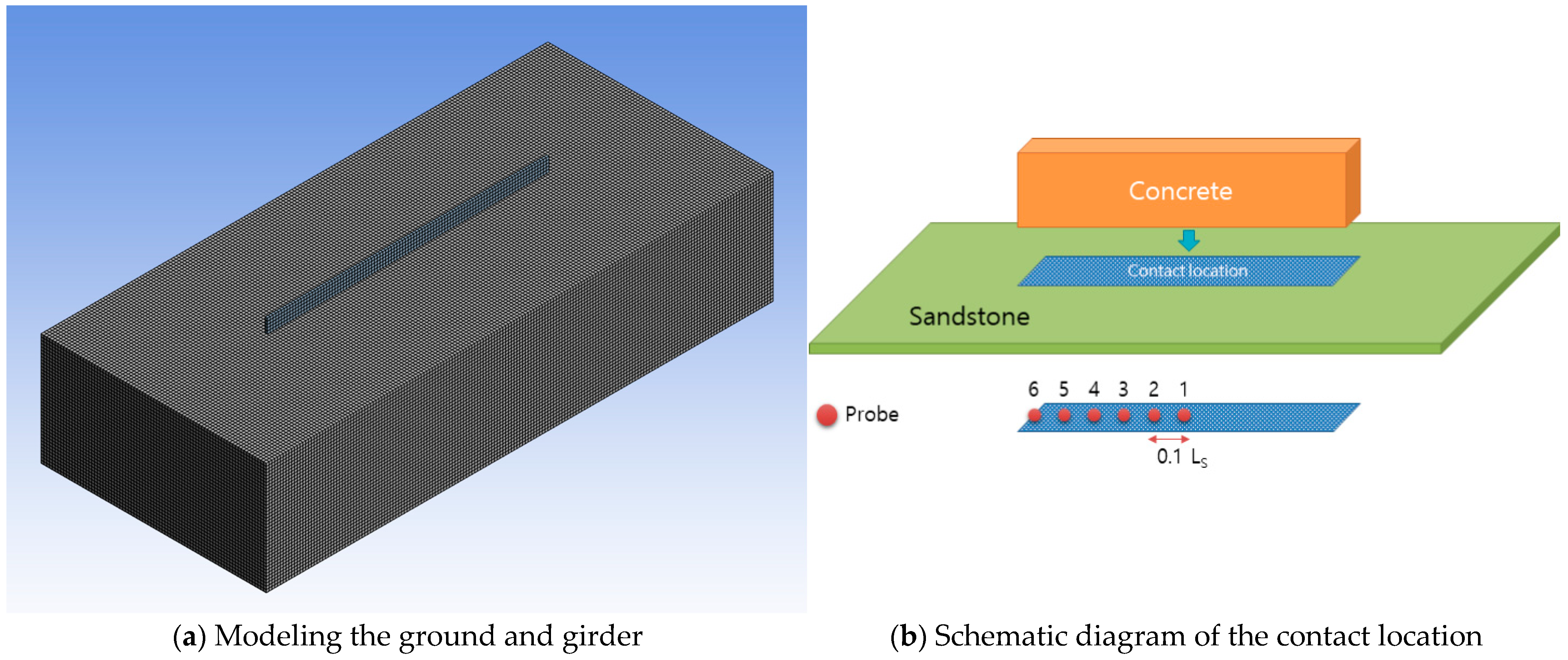
Figure 3 illustrates the geometry and mesh configuration of the numerical model. The girder model (G1–G3) was idealized as a rigid concrete block with variable section dimensions. G1 represents a large-scale PSC girder, 2.5 m in depth and 50 m in span length. G2 represents a medium-span size with a depth of 2.0 m and a length of 40 m. G3 is a relatively small girder, 1.5 m in depth and 30 m in length, designed to simulate short-span bridge structures. All girders are set with a width of 0.4 m and are assumed to have identical material properties. The drop heights (H1 = 20, H2 = 30, H3 = 40, and H4 = 50 m) were considered to represent realistic construction scenarios. The ground was assumed to be homogeneous soil. Concrete was modeled with a Young’s modulus of 30,000 MPa, a Poisson’s ratio of 0.18, and a compressive strength of 41 MPa. The soil layer was characterized by a Young’s modulus of 34,000 MPa, a Poisson’s ratio of 0.23, and a cohesion of 42 MPa. The residual friction angle and cohesion were set to 0.3° and 20 MPa, respectively. The shear and bulk moduli were derived from the standard isotropic elasticity relationships.
The computational mesh consisted of hexahedral elements with an average size of 0.5 m. A mesh frequency resolution of 500 Hz ensured proper representation of the dominant impact-induced vibration components. A fixed boundary condition was assigned at the model base, while lateral boundaries were constrained using non-reflective conditions to prevent wave reflections.
To evaluate the ground motion generated by the impact, displacement, velocity, and acceleration were measured at six probe points located along the contact zone between the girder and ground (Figure 3b). The spacing between adjacent points was set to one-tenth of the girder length. The impact simulation employed a time step of 5 × 10⁻⁵ s to capture rapid contact and wave propagation phenomena. The total simulation time was 0.1 s, sufficient to observe both direct impact and near-field wave propagation effects.
In this study, twelve analysis combinations (3 girder sizes × 4 drop heights) were performed. The case identification follows the notation GiHj, where i and j correspond to girder and height types, summarized in Table 3.
Figure 4 presents the temporal evolution of ground deformation following the impact of the concrete girder (Case G1H1). At the initial moment (T = 0.0016 s), concentrated compression occurred beneath the center of the contact zone where the impact of energy was applied. As time progressed, the stress waves propagated laterally through the ground, forming symmetrical deformation bands along the girder’s longitudinal axis. The central region exhibited the highest displacement amplitude because both sides of the girder provided mechanical restraint during impact, allowing energy accumulation at the center. In contrast, the distal ends of the girder experienced lower impact intensity, as the lack of reaction support led to reduced contact pressure and smaller deformation magnitudes. The deformation fronts reached their maximum extent at approximately T = 0.01 s, after which the wave energy dissipated rapidly through the ground medium.
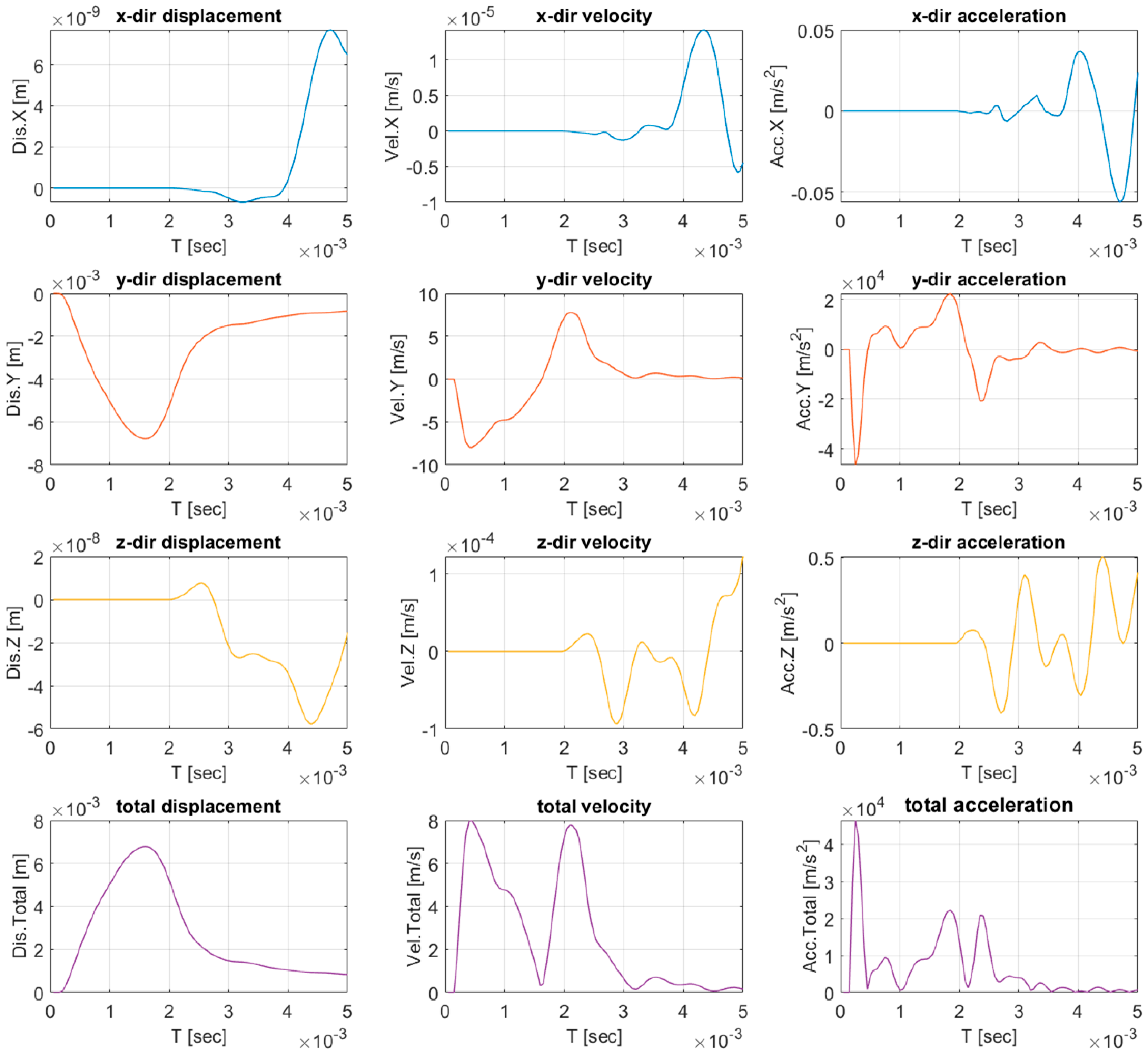
Figure 5 presents the displacement, velocity, and acceleration time histories obtained at the center (probe 1) of the G1H1 case. The results indicate that the dominant response occurred in the vertical (y) direction, corresponding to the impact axis. In the horizontal (x and z) directions, the amplitudes were smaller by several orders of magnitude, confirming that the primary motion was vertically oriented. The total displacement increased sharply at the moment of impact (around 0.0016 s) and decayed after the first oscillation cycle due to material damping and wave dispersion within the ground medium. The overall response exhibited a single dominant impulse without significant secondary oscillations. Thus, when the girder undergoes free drop, a single major impact load is generated upon contact with the ground. The resulting response curve resembled that of an explosion waveform (i.e., [44,45]) and resembles an exponential decay function after the peak (T = 0.00016 s), indicating a rapid release and attenuation of impact energy.
Figure 6 illustrates the vertical displacement time histories measured at Probe 1, where the maximum response was observed. For all girder types (G1–G3), the displacement amplitude increased with drop height, confirming that higher potential energy generated stronger impact-induced ground motion. Among the girder models, G1 exhibited the largest peak displacement, highlighting the influence of mass and contact area on impact energy transmission.
The overall waveform shape was consistent across all cases, while the time to reach the peak showed only minor variation. This trend indicates that larger girders, due to their higher mass and stiffness, required slightly longer durations to reach peak deformation after impact. It was found that both drop height and girder geometry systematically influence the amplitude and timing of impact-induced ground responses.

4. Ground Response for Impact Load

The influence of ground conditions on vibration transmission was evaluated through a series of numerical simulations. The objective of this analysis was to identify attenuation characteristics and propagation behavior of impact-induced ground motion under representative subsurface configurations. The ground medium was modeled as horizontally layered, consisting of topsoil, weathered rock (WR), and soft rock (SR) strata. Only variations in the soil and WR layers were considered to isolate their effects on wave propagation. Site-specific geotechnical data were not incorporated, and each layer was assumed to be homogeneous and isotropic.
The analytical domain was represented by a two-dimensional axisymmetric model using the commercial numerical program FLAC 2D [46]. The 2D axisymmetric model was used to efficiently simulate radially propagating surface waves while preserving the near-field energy characteristics observed in the 3D FEM results. Although the axisymmetric condition cannot capture complex topographic effects, it is suitable for analyzing vibration attenuation with distance. In this study, the primary objective was to investigate the influence of the underground layer. Therefore, the modeling approach proposed by Ahn and Park [47] for blast analysis was adopted.
This modeling approach is suitable for simulating propagation waves generated by vertical impact loading. The mesh was constructed using Constant Strain Triangle (CST) solid elements. The damping coefficients were calibrated to achieve target damping ratios consistent with small-strain conditions, following the method proposed by Ahn and Park [47]. Rayleigh damping formulation can reasonably approximate the energy dissipation characteristics of geomaterials within the small-strain range, where hysteretic and nonlinear effects are negligible [48]. The ground domain was represented as a layered medium consisting of soil, weathered rock, and bedrock. Each layer was characterized by its materials, summarized in Table 4.
In the dynamic analysis, the mesh size of solid elements must be sufficiently small to capture the maximum frequency of propagating waves. According to the empirical criterion proposed by Kuhlemeyer and Lysmer [49], the maximum allowable element size is ΔllV/10f, where V is the wave propagation velocity and f is the predominant frequency). Therefore, the element size was set to 0.5 m, which is adequate to represent frequencies up to 250 Hz. Considering the Nyquist frequency, the computational time step is set to 0.0001 s.
Boundary conditions were defined to eliminate reflections. The model base was fixed, and viscous absorbing boundaries were implemented along the sides and bottom. Since the focus of the analysis was on transient wave propagation rather than permanent deformation, an elastic constitutive model was applied. The vertical impact load was introduced at the ground surface to reproduce the impulsive response generated by the free fall of a girder. Figure 7 illustrates the schematic configuration of the numerical model.
Table 5 summarizes the case matrix used to evaluate the influence of soil and weathered-rock layer thickness on vibration propagation. The soil layer thickness varied from 2 m to 6 m, while the WR layer thickness ranged from 0 to 10 m. This configuration allowed evaluation of both single-layer and composite-layer profiles, representing a wide range of realistic ground conditions.
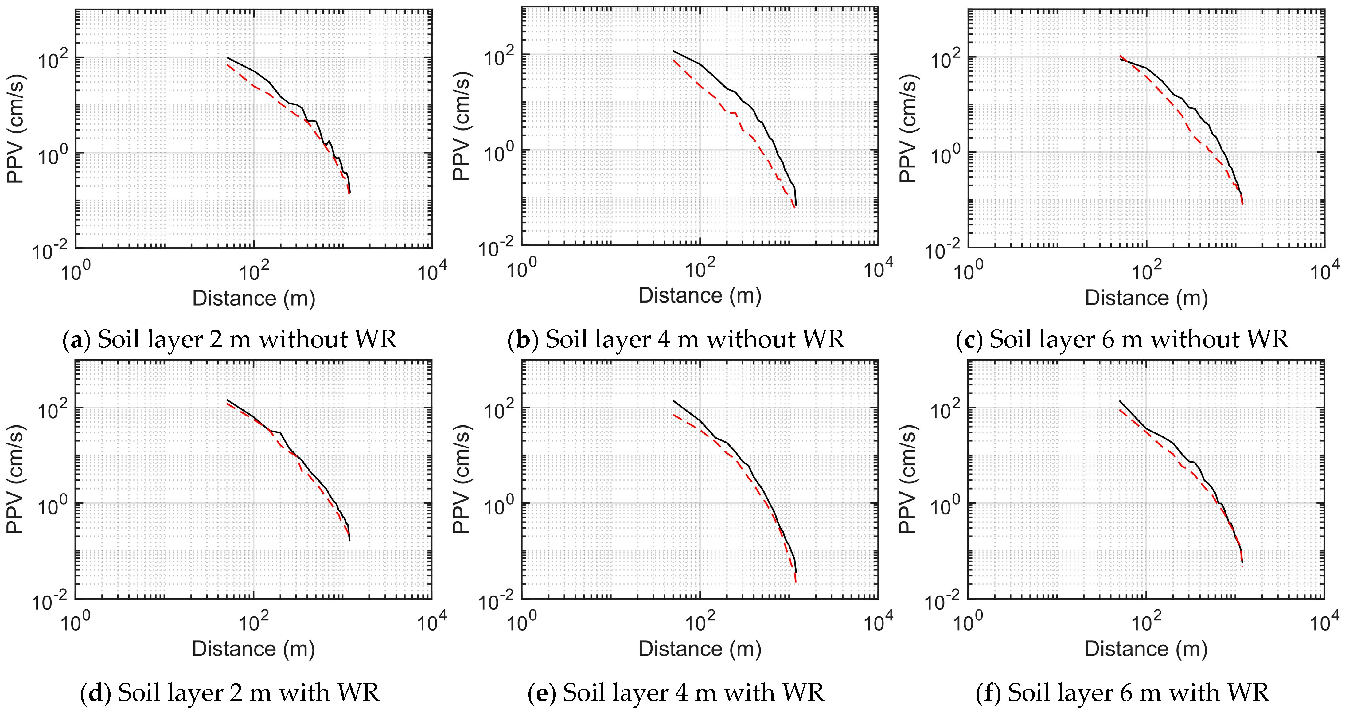
Figure 8 presents the variation in peak particle velocity (PPV) with distance for different soil and WR configurations. In all cases, PPV exhibited a logarithmic decay with distance, which is consistent with the typical attenuation behavior of near-field impact vibrations. The attenuation patterns of vertical and horizontal components were similar in shape, although the vertical component showed a slightly steeper gradient due to its stronger coupling with the impact direction. The initial PPV near the source was slightly higher in the models including a WR layer, indicating that a stiffer intermediate layer facilitates more efficient transmission of vibrational energy prior to dissipation. As the soil thickness increased from 2 m to 6 m, the attenuation slope became steeper, reflecting the greater energy loss associated with thicker, more dissipative soils. This behavior results from impedance contrasts between the soil and WR interfaces, which cause partial wave reflection and refraction during propagation.
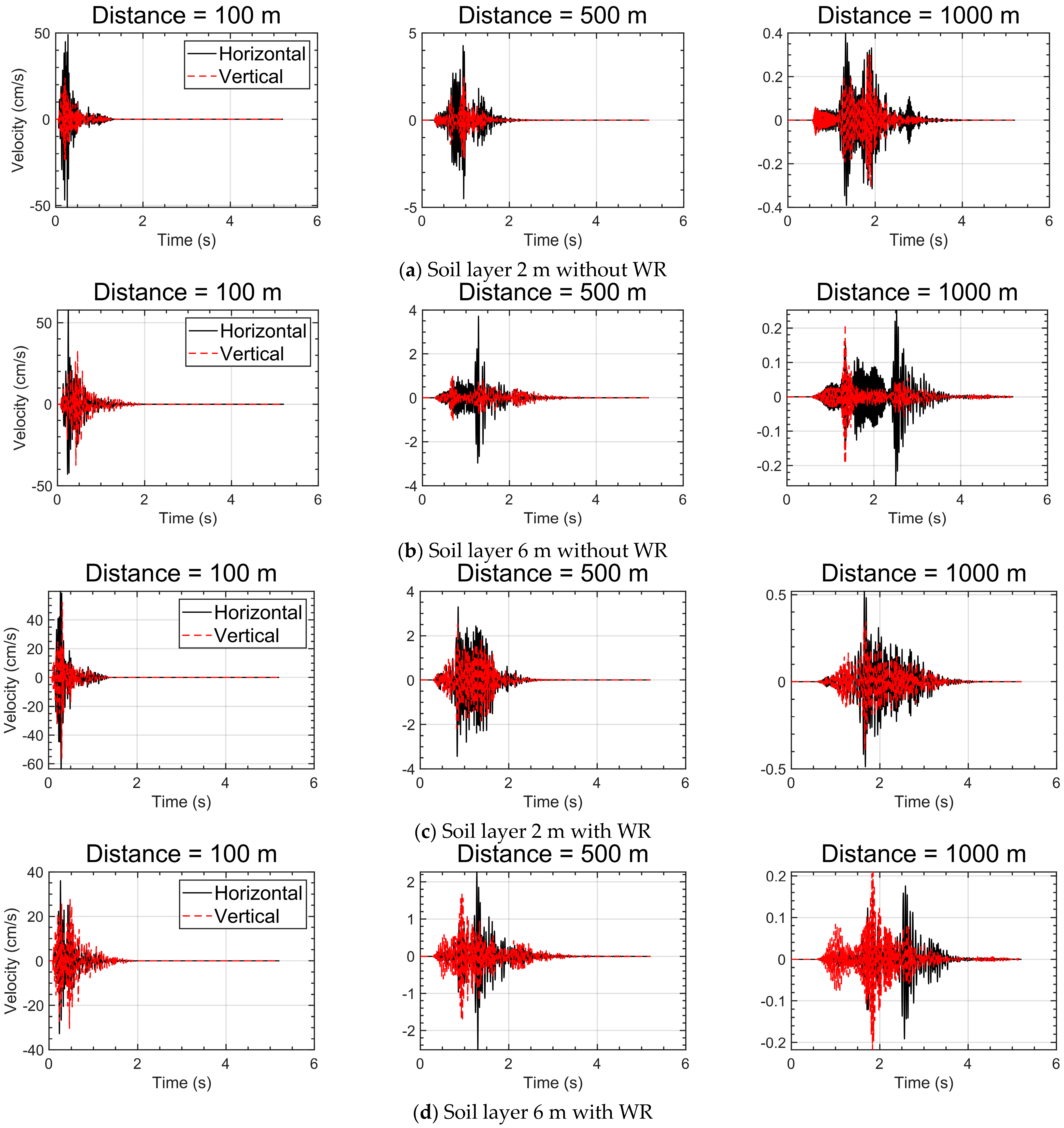
Figure 9 compares the velocity time histories at distances of 100 m, 500 m, and 1000 m for cases with and without a WR layer. In the absence of WR, the vertical component decreased significantly with increasing soil thickness and distance. For the 2 m soil layer, distinct vertical reflections were observed near the source, indicating strong interference between incident and surface-reflected waves. As the soil layer thickened to 6 m, these reflections diminished, implying enhanced energy dissipation and internal scattering that suppressed secondary wave interference. When a WR layer was included, the overall amplitude of the vertical component increased. This amplification was attributed to impedance contrast at the soil–WR boundary, where partial reflection of downward-propagating waves enhances the vertical motion in the near field. The effect was most pronounced for the thinner soil case (2 m), where the reflection interface was closer to the surface. For thicker soil layers, the reflected energy was partially dissipated through scattering and damping before reaching the surface, resulting in smoother, less oscillatory waveforms.
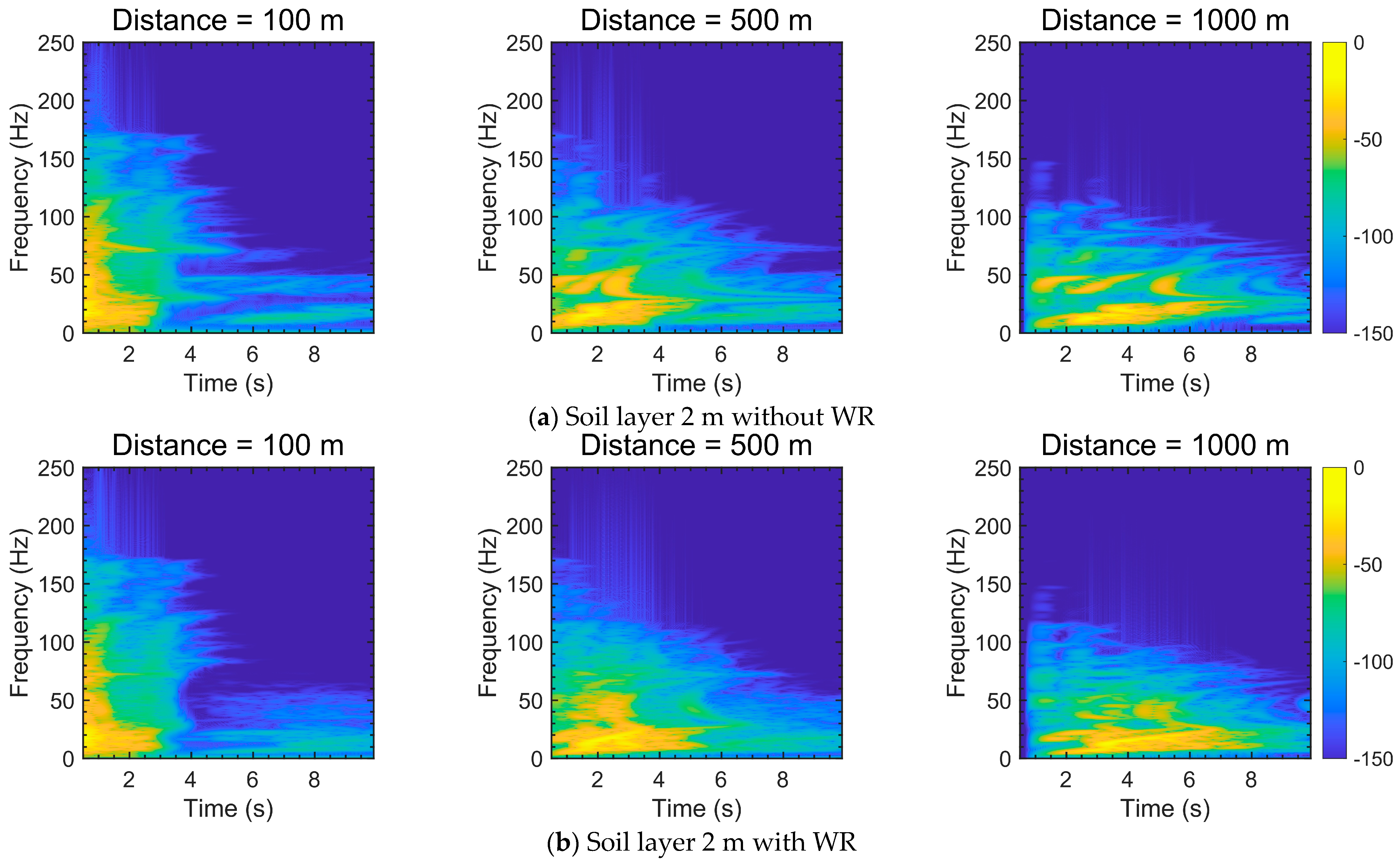
The short-time Fourier transform (STFT) results in Figure 10 illustrate the evolution of frequency content with distance for the 2 m soil case. Without a WR layer, spectral energy was concentrated primarily between 40 and 100 Hz near the source. High-frequency components attenuated rapidly with distance, and energy gradually shifted toward frequencies below 40 Hz, demonstrating frequency-dependent damping behavior.
In contrast, the presence of a WR layer introduced an additional energy concentration within the 60–120 Hz range during the initial phase of wave arrival. This phenomenon reflected partial reflection and constructive interference at the soil–WR interface, which prolongs the persistence of mid-frequency components. At larger distances (≥1000 m), this reflected energy became increasingly diffused due to geometric spreading and damping. Overall, the WR layer amplified near-field spectral energy and slightly delayed the decay of mid-frequency components, supporting the earlier observation that impedance contrast enhances vertical motion and extends vibration duration.
The results of this chapter confirm two principal attenuation mechanisms: (1) Effect of soil thickness: Increasing soil thickness enhances damping and scattering, reducing vertical wave reflections and suppressing high-frequency vibration components; (2) Effect of WR layer: The presence of a WR layer amplifies the near-field vertical response by generating impedance-induced reflections, which increase PPV and spectral intensity. These findings highlight that both the composition and layering of the subsurface significantly influence the amplitude, duration, and frequency characteristics of impact-induced ground motion.

5. Conclusions

This study numerically examined the vibration characteristics of accidental impact loads and the corresponding ground responses under various subsurface conditions. The hybrid finite-element and finite-difference analyses reproduced the transient motions generated by the free fall of bridge girders and identified the dominant mechanisms governing vibration propagation and attenuation.
  • The impact of a falling girder generated a single impulsive waveform characterized by a sharp amplitude peak and subsequent exponential decay. This behavior is similar to the analytical form of an explosive load [44], suggesting that a theoretical approach can be applied. However, because the propagation direction varies with the falling configuration, accurate analytical estimation remains challenging.
  • Both drop height and girder mass showed a direct correlation with vibration amplitude and response duration. This result confirmed a proportional relationship between potential energy and impact-induced ground-motion intensity. Therefore, the geometric and kinetic characteristics of the impacting body jointly govern the amplitude and temporal evolution of the generated ground motion.
  • The attenuation of peak particle velocity followed a logarithmic decay pattern typical of near-field propagation. Increasing soil thickness enhanced damping, whereas thinner soils transmitted energy more efficiently and produced stronger vertical reflections. This result indicates that the attenuation behavior strongly depends on subsurface layering and impedance contrast between materials.
  • The presence of a weathered-rock layer amplified near-surface vertical motions through impedance-induced reflections and constructive interference when the soil layer was thin. The amplification was most evident where the impedance contrast between soil and weathered rock was large.
  • Although this study relied solely on numerical simulations, the results provide a quantitative basis for interpreting impulsive ground motions generated by accidental impacts. Future research should include controlled drop tests and field measurements to validate the numerical simulation and to develop empirical attenuation relationships applicable to engineering assessment of impact-induced vibrations.

Author Contributions

J.-K.A.: writing—original draft preparation, methodology. Y.-G.L. & M.Y.: writing—review, visualization. S.-R.L.: writing—review and editing, project administration, supervision. C.P.: writing—review and editing, supervision. J.S.M.: writing—review and editing, visualization, methodology. The authors confirm that this work has not been published before. All authors have read and agreed to the published version of the manuscript.

Funding

This research was supported by the Regional Innovation System & Education (RISE) program through the Gangwon RISE Center, funded by the Ministry of Education (MOE) and the Gangwon State (G.S.), Republic of Korea (2025-RISE-10-002).

Data Availability Statement

Data are contained within the article.

Conflicts of Interest

The authors declare no conflicts of interest.

References

  1. Karki, T.B.; Manandhar, R.B.; Neupane, D.; Mahat, D.; Ban, P. Critical analysis of noise pollution and its effect on human health. Int. J. Educ. Life Sci. 2024, 2, 161–176. [Google Scholar] [CrossRef]
  2. Caorsi, V.; Guerra, V.; Furtado, R.; Llusia, D.; Miron, L.R.; Borges-Martins, M.; Márquez, R. Anthropogenic substrate-borne vibrations impact anuran calling. Sci. Rep. 2019, 9, 19456. [Google Scholar] [CrossRef]
  3. McQueen, A.D.; Wilkens, J.L.; Katzenmeyer, A.W.; Harrington, H.F.; Suedel, B.C. Assessing the impacts of dry blasting on fish eggs in adjacent spawning habitat. Bull. Environ. Contam. Toxicol. 2022, 108, 190–195. [Google Scholar] [CrossRef] [PubMed]
  4. Summers, J.L.; White, J.P.; Kaarakka, H.M.; Hygnstrom, S.E.; Sedinger, B.S.; Riddle, J.; Yahnke, C. Influence of underground mining with explosives on a hibernating bat population. Conserv. Sci. Pract. 2023, 5, e12849. [Google Scholar] [CrossRef]
  5. Zhang, P.; Zhang, H.; Liu, Y.; Liao, Y.; Wu, Q.; Liu, J. Evaluation of indicators of railway-induced annoying vibration based on building measurements developed by TOD: A discussion. Phys. Scr. 2024, 99, 025008. [Google Scholar] [CrossRef]
  6. Jiao, Y.; Wang, Z.; Li, C.; Yao, Z.; Dong, R.; Cui, S.; Wang, T. How to enhance urban noise management: Exploring the influencing factors of noise complaints at multiple scales integrating citizen perception. Environ. Impact Assess. Rev. 2025, 112, 107783. [Google Scholar] [CrossRef]
  7. Wald, D.J.; Quitoriano, V.; Heaton, T.H.; Kanamori, H. Relationships between peak ground acceleration, peak ground velocity, and modified Mercalli intensity in California. Earthq. Spectra 1999, 15, 557–564. [Google Scholar] [CrossRef]
  8. Wu, Y.M.; Teng, T.L.; Shin, T.C.; Hsiao, N.C. Relationship between peak ground acceleration, peak ground velocity, and intensity in Taiwan. Bull. Seismol. Soc. Am. 2003, 93, 386–396. [Google Scholar] [CrossRef]
  9. Ghobarah, A. Performance-based design in earthquake engineering: State of development. Eng. Struct. 2001, 23, 878–884. [Google Scholar] [CrossRef]
  10. Petersen, M.D.; Shumway, A.M.; Powers, P.M.; Field, E.H.; Moschetti, M.P.; Jaiswal, K.S.; Witter, R.C. The 2023 US 50-state national seismic hazard model: Overview and implications. Earthq. Spectra 2024, 40, 5–88. [Google Scholar] [CrossRef]
  11. Amnieh, H.B.; Siamaki, A.; Soltani, S. Design of blasting pattern in proportion to the peak particle velocity (PPV): Artificial neural networks approach. Saf. Sci. 2012, 50, 1913–1916. [Google Scholar] [CrossRef]
  12. Kumar, R.; Choudhury, D.; Bhargava, K. Determination of blast-induced ground vibration equations for rocks using mechanical and geological properties. J. Rock Mech. Geotech. Eng. 2016, 8, 341–349. [Google Scholar] [CrossRef]
  13. Havskov, J.; Alguacil, G. Instrumentation in Earthquake Seismology; Springer: Dordrecht, The Netherlands, 2004. [Google Scholar]
  14. Wielandt, E. Seismic sensors and their calibration. In New Manual of Seismological Observatory Practice 2 (NMSOP-2); Deutsches GFZ: Potsdam, Germany, 2012; pp. 1–51. [Google Scholar]
  15. Moravvej, M.; El-Badry, M. Reference-free vibration-based damage identification techniques for bridge structural health monitoring—A critical review and perspective. Sensors 2024, 24, 876. [Google Scholar] [CrossRef]
  16. Massarsch, K.R.; Broms, B.B. Damage criteria for small amplitude ground vibrations. In Proceedings of the 2nd International Conference on Recent Advances in Geotechnical Earthquake Engineering and Soil Dynamics, St. Louis, MI, USA, 11–15 March 1991. [Google Scholar]
  17. Ataei, M. Evaluation of blast-induced ground vibrations from underground excavation at Karoun 3 area. Min. Technol. 2010, 119, 7–13. [Google Scholar] [CrossRef]
  18. Ragam, P.; Komalla, A.R.; Kanne, N. Estimation of blast-induced peak particle velocity using ensemble machine learning algorithms: A case study. Noise Vib. Worldw. 2022, 53, 404–413. [Google Scholar] [CrossRef]
  19. Khan, M.F.H.; Hossain, M.J.; Ahmed, M.T.; Monir, M.U.; Rahman, M.A.; Sweety, T.S.; Shovon, S.M. Ground vibration effect evaluation due to blasting operations. Heliyon 2025, 11, e41759. [Google Scholar] [CrossRef]
  20. Ekanayake, S.D.; Liyanapathirana, D.S.; Leo, C.J. Influence zone around a closed-ended pile during vibratory driving. Soil Dyn. Earthq. Eng. 2013, 53, 26–36. [Google Scholar] [CrossRef]
  21. Wang, W.; Wu, J.; Wei, J.; Chen, J.; Zhan, J. Field test on internal soil vibrations induced by resonance-free steel pipe pile driving. KSCE J. Civ. Eng. 2025, 29, 100202. [Google Scholar] [CrossRef]
  22. Avillez, J.; Frost, M.; Cawser, S.; Skinner, C.; El-Hamalawi, A.; Shields, P. Procedures for estimating environmental impact from railway induced vibration: A review. In Proceedings of the ASME 2012 Noise Control and Acoustics Division Conference, New York, NY, USA, 19–22 August 2012; Volume 45325, pp. 381–392. [Google Scholar]
  23. Liu, X.; Xiao, Y.; Jiang, H.; Guo, Y.; Yu, M.; Tan, W. Analogical assessment of train-induced vibration and radiated noise in a proposed theater. Sensors 2023, 23, 505. [Google Scholar] [CrossRef]
  24. Zhang, Y.; Kwan, M.P.; Ma, H. Sensing noise exposure and its inequality based on noise complaint data through vision-language hybrid method. Appl. Geogr. 2024, 171, 103369. [Google Scholar] [CrossRef]
  25. Li, X.; Huan, H.; Lin, H.; Li, Z.; Du, F.; Cao, Z.; Ren, H. Determination Method of Rational Position for Working Face Entries in Coordinated Mining of Section Coal Pillars and Lower Sub-Layer. Sci. Rep. 2025, 15, 29440. [Google Scholar] [CrossRef]
  26. DIN 4150; Vibration in Buildings—Part 3: Effects on Structures. Deutsches Institut für Normung: Berlin, Germany, 1999.
  27. BS 7385-2; Evaluation and Measurement for Vibration in Buildings. Part 2: Guide to Damage Levels from Groundborne Vibration. BSI: London, UK, 1993.
  28. Athanasopoulos, G.A.; Pelekis, P.C. Ground vibrations from sheetpile driving in urban environment: Measurements, analysis and effects on buildings and occupants. Soil Dyn. Earthq. Eng. 2000, 19, 371–387. [Google Scholar] [CrossRef]
  29. Siskind, D.E.; Stagg, M.S.; Kopp, J.W.; Dowding, C.H. Structure Response and Damage Produced by Ground Vibration from Surface Mine Blasting; Report RI-8507; U.S. Bureau of Mines: Washington, DC, USA, 1980. [Google Scholar]
  30. Jongmans, D. Prediction of ground vibrations caused by pile driving: A new methodology. Eng. Geol. 1996, 42, 25–36. [Google Scholar] [CrossRef]
  31. Ray, M.N.; Belhe, R.; Vaidya, N.R.; Ozkan, M.K. Vibration response in pile foundation embedded in soil due to underground explosion. In Proceedings of the International Conference on Structural Mechanics in Reactor Technology (SMiRT), Busan, Republic of Korea, 20–25 August 2017; pp. 20–25. [Google Scholar]
  32. Sun, Z.; Yu, H.; Li, C.; Liu, R.; Li, Q.; Su, C. Ground and pile vibrations induced by pile driving. Buildings 2023, 13, 1884. [Google Scholar] [CrossRef]
  33. Mayne, P.W.; Jones, J.S., Jr.; Dumas, J.C. Ground response to dynamic compaction. J. Geotech. Eng. 1984, 110, 757–774. [Google Scholar] [CrossRef]
  34. Wu, S.; Wei, Y.; Zhang, Y.; Cai, H.; Du, J.; Wang, D.; Xiao, J. Dynamic compaction of a thick soil-stone fill: Dynamic response and strengthening mechanisms. Soil Dyn. Earthq. Eng. 2020, 129, 105944. [Google Scholar] [CrossRef]
  35. Li, J.; Wang, W.; Luo, L.; Yao, X.; Hu, J. Evaluation of dynamic compaction load conversion methods and vibration reduction treatments. Buildings 2024, 15, 111. [Google Scholar] [CrossRef]
  36. Lin, F.; Li, Y.; Gu, X.; Zhao, X.; Tang, D. Prediction of ground vibration due to the collapse of a 235 m high cooling tower under accidental loads. Nucl. Eng. Des. 2013, 258, 89–101. [Google Scholar] [CrossRef]
  37. Lin, F.; Zhong, Q. Mitigation of ground vibration due to collapse of a large-scale cooling tower with novel application of materials as cushions. Shock Vib. 2017, 2017, 6809246. [Google Scholar] [CrossRef]
  38. Yan, Y.; Hou, X.; Cao, S.; Li, R.; Zhou, W. Forecasting the collapse-induced ground vibration using a GWO-ELM model. Buildings 2022, 12, 121. [Google Scholar] [CrossRef]
  39. The Ministry of Land, Infrastructure and Transport. Sejong-Pocheon Expressway Construction Site Girder Collapse Accident Investigation Report; The Ministry of Land, Infrastructure and Transport: Sejong, Republic of Korea, 2025. [Google Scholar]
  40. Korea Authority of Land & Infrastructure Safety. Girder Collapse Accident at the Siheung Bridge Construction Site Investigation Report; Korea Authority of Land & Infrastructure Safety: Jinju, Republic of Korea, 2024. [Google Scholar]
  41. The Ministry of Land, Infrastructure and Transport. Pyeongtaek International Bridge Girder Collapse Accident Investigation Report; The Ministry of Land, Infrastructure and Transport: Sejong, Republic of Korea, 2018. [Google Scholar]
  42. Lin, F.; Jiang, W. Design-Oriented Acceleration Response Spectrum for Ground Vibrations Caused by Collapse of Large-Scale Cooling Towers in NPPs. Nucl. Eng. Technol. 2018, 50, 1402–1411. [Google Scholar] [CrossRef]
  43. Park, S.; Baek, J.; Kim, K.; Park, Y.J. Study on Reduction Effect of Vibration Propagation Due to Internal Explosion Using Composite Materials. Int. J. Concr. Struct. Mater. 2021, 15, 30. [Google Scholar] [CrossRef]
  44. Duvall, W.I. Strain-wave shapes in rock near explosions. Geophysics 1953, 18, 310–323. [Google Scholar] [CrossRef]
  45. Jiang, J.; Blair, D.P.; Baird, G.R. Dynamic response of an elastic and viscoelastic full-space to a spherical source. Int. J. Numer. Anal. Methods Geomech. 1995, 19, 181–193. [Google Scholar] [CrossRef]
  46. Itasca Consulting Group, Inc. FLAC—Fast Lagrangian Analysis of Continua, Version 8.1: User’s Guide; Itasca Consulting Group, Inc.: Minneapolis, MN, USA, 2022. [Google Scholar]
  47. Ahn, J.K.; Park, D. Prediction of near-field wave attenuation due to a spherical blast source. Rock Mech. Rock Eng. 2017, 50, 3085–3099. [Google Scholar] [CrossRef]
  48. Ahn, J.K.; Park, D.; Yoo, J.K. Estimation of damping ratio of rock mass for numerical simulation of blast-induced vibration propagation. Jpn. Geotech. Soc. Spec. Publ. 2016, 2, 1589–1592. [Google Scholar] [CrossRef]
  49. Kuhlemeyer, R.L.; Lysmer, J. Finite element method accuracy for wave propagation problems. J. Soil Mech. Found. Div. 1973, 99, 421–427. [Google Scholar] [CrossRef]
Figure 1. Photographs of major accidental impact events that occurred during bridge construction. (a) Event A [39]; (b) Event B [40]; (c) Event C [41].
Applsci 15 12068 g001
Figure 2. Spatial distribution of seismic stations and recorded waveforms for the accidental impact events: (a) shows the locations of regional seismic stations within a 30 km radius (blue dashed circle) from each event site and the epicenter of the mainshock event (black five-pointed star). Triangular symbols denote seismic observation stations; filled blue triangles represent stations operated by the KMA. (b) shows the vertical-component acceleration records at selected stations (CEA2, GSG, and ASNA); Yellow dashed boxes indicate the time windows where impact-induced signals were presumed to arrive.
Applsci 15 12068 g002
Figure 3. Schematic of the numerical model used for impact simulation.
Applsci 15 12068 g003
Figure 4. Time-dependent propagation of impact-induced ground deformation (Case G1H1). These areas correspond to the regions where compressive and shear waves overlap, indicating the highest transient displacement or velocity amplitude within the soil medium.
Applsci 15 12068 g004
Figure 5. Displacement, velocity, and acceleration time histories (Case G1H1).
Applsci 15 12068 g005
Figure 6. Comparison of displacement time histories at Probe 1 for different heights and girder sizes.
Applsci 15 12068 g006
Figure 7. Schematic of the numerical model for 2D analysis.
Applsci 15 12068 g007
Figure 8. Comparison of layer combination for cases: the black line is the horizontal component peak particle velocity (PPV), and the red dotted line is the vertical component PPV.
Applsci 15 12068 g008
Figure 9. Comparison of horizontal and vertical velocity time histories at different distances.
Applsci 15 12068 g009
Figure 10. Short-Time Fourier Transform (STFT) of surface ground velocity at different distances for the 2 m soil layer.
Applsci 15 12068 g010
Table 1. Energy level and vibration characteristics of major construction-induced sources.
SourceEnergy
(TNT Equivalent)
fp
(Hz)
Duration
(s)
CharacteristicsReferences
Blasting107–109 J
(3–300 kg)
5–100<1Short-duration, high-energy[12,29]
Pile Driving106–108 J
(0.3–30 kg)
10–200Continuous impactsMedium energy,
repetitive pulses,
[30,31,32]
Dynamic Compaction 105–106 J
(0.03–0.3 kg)
20–80ContinuousSurface-confined, low amplitude[33,34,35]
Accidental ImpactScales from falling mass, drop heighthighimpulsiveHigh-frequency transient impulse[36,37,38]
Table 2. Estimated Potential Energy for Accidental Impact Events.
EventStructural TypeEstimated Mass (ton)Height (m)Estimated Energy (J)TNTEquivalent (kg)
APSC I-girder
(50 m span, 6 girders)
42047.51.96 × 10847
BPSC I-girder
(55 m span, 9 girders)
540201.10 × 10826
CPSC Box-girder
(160 m span)
300185.30 × 10713
Table 3. Case matrix of combinations.
Drop HeightG1G2G3
50 mG1H1G2H1G3H1
40 mG1H2G2H2G3H2
30 mG1H3G2H3G3H3
20 mG1H4G2H4G3H4
Table 4. Material properties of ground layers.
MaterialUnit Weight
(kN/m3)
P-Wave Velocity
(m/s)
S-Wave Velocity
(m/s)
Poisson’s
Ratio
Damping
Ratio (%)
Soil18.54502750.350.5
Weathered Rock (WR)21.09305750.310.5
Soft Rock (SR)23.0169010600.270.5
Table 5. Case matrix of geo-layer condition.
TypeSoil Layer 2 mSoil Layer 4 mSoil Layer 6 m
without WRWR layer 0 mWR layer 0 mWR layer 0 m
with WRWR layer 10 mWR layer 8 mWR layer 6 m
Disclaimer/Publisher’s Note: The statements, opinions and data contained in all publications are solely those of the individual author(s) and contributor(s) and not of MDPI and/or the editor(s). MDPI and/or the editor(s) disclaim responsibility for any injury to people or property resulting from any ideas, methods, instructions or products referred to in the content.