Article

Design Space Exploration and Performance Evaluation of Aerodynamic Appendages for a Racing Motorcycle Prototype Through a Parametric Multi-Software Workflow

by
Massimiliano Chillemi
1,
Alessandro Caristi
2,
Filippo Cucinotta
1,*,
Giacomo Risitano
1 and
Emmanuele Barberi
1
1
Department of Engineering, University of Messina, Contrada di Dio, 98166 Messina, Italy
2
Motorcycle Testing Department, Pirelli Tyre s.p.a., Via Pagano 15, 95014 Giarre, Italy
*
Author to whom correspondence should be addressed.
Appl. Sci. 2025, 15(22), 12064; https://doi.org/10.3390/app152212064
Submission received: 10 October 2025 / Revised: 6 November 2025 / Accepted: 9 November 2025 / Published: 13 November 2025
(This article belongs to the Special Issue Advances in Computational and Experimental Fluid Dynamics)

Abstract

The aerodynamic performance of racing motorcycles plays a crucial role in improving speed, stability, and rider control under dynamic conditions. While most existing studies focus on front-mounted winglets and fairing extensions, the aerodynamic role of rear fairing appendages remains comparatively unexplored despite their potential influence on drag, downforce distribution, and wake behaviour. In this work, three alternative rear winglet configurations were parametrically designed in Siemens NX and systematically evaluated within a validated CFD framework based on Simcenter STAR-CCM+, with the aim of assessing how geometric variations influence aerodynamic performance and achieve a favourable trade-off between reduced aerodynamic resistance and enhanced rear downforce. The numerical setup employed has been previously validated against wind-tunnel measurements in similar aerodynamic applications, ensuring the reliability and accuracy of the predicted flow fields. A Design Space Exploration (DSE) was performed through an automated multi-software workflow, enabling systematic variation in key geometric parameters and real-time assessment of their aerodynamic effects. The study revealed distinct influences of the different configurations on drag and lift coefficients, as well as on wake structure and flow detachment, highlighting the critical aerodynamic mechanisms governing rear stability and flow closure. Through iterative design and simulation, the workflow identified the most effective configuration, achieving a balance between reduced aerodynamic resistance and increased downforce, both essential for competitive racing performance. The results demonstrate the potential of integrating parametric modelling, automated CFD simulation, and DSE optimization in the aerodynamic design phase. This methodology not only offers new insights into the scarcely studied rear aerodynamic region of racing motorcycles but also establishes a replicable framework for future developments involving advanced optimization algorithms, experimental validation, and wake-interaction analyses between leading and trailing riders.

1. Introduction

Aerodynamics plays a crucial role in the development of racing motorcycles, as it directly influences drag, downforce, stability, and rider control during all phases of motion, including cornering, braking, and acceleration [1,2]. In the last decade, its importance has grown dramatically, especially in world championships such as MotoGP, Moto2, Moto3, and SuperBike, where teams continuously experiment with innovative solutions to gain competitive advantages in terms of speed, stability, and handling [3]. This trend has been further accelerated by regulatory changes and the widespread introduction of aerodynamic appendages such as winglets [4] and fairing extensions, which have reshaped the design philosophy of modern racing motorcycles [2,5]. A decisive factor in this progress has been the rapid evolution of computational methods, particularly Computational Fluid Dynamics (CFD). CFD, which numerically solves the Navier–Stokes equations over discretized meshes, has become an indispensable tool for designers, allowing them to investigate complex flow structures, evaluate wake behaviour, analyse pressure distribution, and quantify aerodynamic forces such as drag and lift both in terrestrial and non-terrestrial applications [6,7,8,9,10]. Recent frontier achievements in advanced numerical methods, including multi-field coupling simulations and in situ calibration techniques based on virtual samples and autoencoders [11,12], illustrate the increasing capability of modern computational workflows to handle complex, coupled physical phenomena efficiently.
Through CFD, multiple design iterations can be performed efficiently, enabling the optimization of aerodynamic components long before wind tunnel campaigns or on-track testing, and thereby making aerodynamic development both more precise and more cost-effective [2,13,14,15]. Several studies have investigated the impact of aerodynamic devices on motorcycles, often focusing on front-mounted wing kits and their ability to enhance downforce while balancing the inevitable increase in drag. Chien and Wang [5] analysed a racing motorcycle equipped with an aerodynamic wing kit based on the NACA 4412 profile, applying CFD simulations with k–ω SST and LES turbulence models, and demonstrated the potential of such devices to improve the downforce-to-drag ratio under different operating conditions. Similarly, Wiński and Piechna [2] performed comprehensive CFD simulations of a sport motorcycle, including the presence of a rider, and highlighted the aerodynamic complexity arising from exposed wheels, body geometry, and rider posture. More recently, attention has also been directed toward the aerodynamic interaction between leading and pursuing motorcycles, as the vortical wake generated by downforce-producing appendages may alter the pressure field encountered by a following rider.
One of the first notable aerodynamic innovations in motorcycle racing emerged around 2011, when Ducati, in collaboration with Valentino Rossi, tested aerodynamic appendages mounted on the flanks of its MotoGP prototype. These side fairing extensions were designed to manipulate airflow, improve attachment, and enhance high-speed stability, although Rossi reportedly found that they did not suit his riding style. A more prominent breakthrough followed in 2015 with the Ducati GP15, ridden by Andrea Iannone, which introduced front-mounted winglets and enlarged side fairing elements. The goal of this configuration was to generate sufficient downforce to reduce front-end lift and wheelies, improving straight-line stability without significantly compromising top speed, given the high power output of MotoGP engines. Photographic documentation from that period shows Ducati experimenting with different winglet geometries and sizes, including fairing extensions around the handlebars to comply with regulatory width limits.
Following Ducati’s success, other manufacturers quickly adopted similar solutions. Honda, for instance, began testing aerodynamic winglets in early 2016 on its factory prototypes. Riders such as Dani Pedrosa and Marc Márquez reported noticeable changes in handling, acknowledging both the benefits in front-end stability and potential drawbacks under specific conditions. These early designs primarily aimed to reduce front lift during acceleration and to improve rear wheel traction and vehicle stability at high speed.
Historically, the pursuit of aerodynamic efficiency in motorcycles dates back even further. The Bimota YB1 (1974–1975), designed by Massimo Tamburini, featured fully enveloping bodywork that minimized drag and reduced the exposed frontal area, demonstrating an early awareness of aerodynamics in racing motorcycle design. Although aerodynamic understanding at the time lacked modern computational tools, the YB1 highlighted the crucial interplay between fairing design, rider position, and overall aerodynamic performance, a principle later refined through Ducati’s modern winglet developments.
From a technical point of view, CFD now allows for a level of detail that was impossible in earlier decades. Mesh generation, turbulence modelling (such as k–ω SST, LES, RANS hybrids) [16,17,18], transient vs. steady simulations, wake structure visualization, and vortex shedding analysis all provide insight into how small shape changes (in winglet angle, size, or position) affect pressure distribution, drag coefficient, lift/downforce, and also dynamic stability under yaw, pitch, and roll. The wake closure phenomenon, where rear fairing shapes or appendices reduce turbulent wake size or promote smoother flow separation, has been recognized in recent academic work as having implications not just for a single motorcycle’s drag and downforce, but also how trailing motorcycles are affected by the disturbed flow field.
While the introduction of aerodynamic appendages in MotoGP and other racing series has driven technological progress, the academic literature has followed with systematic investigations into motorcycle aerodynamics, particularly through CFD and experimental validation. Unlike anecdotal reports from racing teams, these studies provide reproducible results and frameworks for understanding the aerodynamic mechanisms that govern drag, lift, stability, and wake interactions [19,20]. One of the earliest comprehensive CFD-based analyses of motorcycle aerodynamics was carried out by Angeletti et al. [21], who demonstrated the applicability of CFD tools to complex geometries including the rider and rotating wheels. Their work established that accurate modelling of wheel rotation and rider posture is essential to capture realistic flow separation and vortex structures. More recently, Palanivendhan et al. [22] designed and evaluated a complete aerodynamic kit for a racing motorcycle, showing that relatively small fairing modifications could lead to reductions in drag and improvements in stability without compromising top speed. Similarly, González-Arcos and Gamez-Montero [3] investigated MotoGP flow redirectors, demonstrating how targeted geometric modifications affect pressure fields, wake dimensions, and aerodynamic load transfer between the wheels. Beyond steady-state CFD analyses, transient and crosswind effects have been addressed in detail. Fintelman et al. [23] conducted numerical simulations of motorcycles under yawed flow conditions, finding that side winds and unsteady wake interactions substantially affect stability and load distribution, with implications for both safety and performance. These insights underline the importance of studying appendages not only in straight-line configurations but also in dynamic race scenarios. The role of wake interactions between motorcycles has also been investigated. In their study, An and Fung [24] analysed aerodynamic interactions between cyclists and following motorcycles, showing that leading vehicles generate disturbed flow fields that significantly alter the aerodynamic loads on trailing riders. Although their study focused on cycling, the principles translate directly to motorcycle racing, where rear appendages can either mitigate or exacerbate the slipstreaming advantage of opponents.
Despite the wealth of developments, there remains limited published literature focusing specifically on rear fairing winglets integrated into the tail section of racing motorcycles, their combined effect on drag reduction, downforce at the rear, wake closure, and stability.
Recent studies on motorcycle aerodynamics have mainly focused on front-mounted winglets and fairing modifications to enhance downforce, stability, and wheelie control through CFD-based analyses and simplified dynamic models. However, peer-reviewed investigations addressing rear aerodynamic appendages, such as fins, spoilers, or swingarm devices, remain limited, despite their growing use in modern racing motorcycles to improve high-speed stability and braking performance. Unlike front wings, tail-mounted components operate within the separated wake behind the rider and rear wheel, where flow mechanisms involve wake contraction, pressure recovery, and rear load redistribution. Recent findings indicate that optimizing tail geometry or integrating extractive passages can shorten wake length, reduce turbulent kinetic energy, and slightly increase rear downforce, offering an effective means to enhance aerodynamic balance and vehicle stability under racing conditions.
The present study aims to address this research gap by employing a Design Space Exploration (DSE) approach to design and evaluate alternative rear winglet configurations for a racing motorcycle prototype, including the generation of hollow shapes, as done in other fields. The winglet geometries were parametrically modelled in Siemens NX and integrated into a validated CFD environment using Simcenter STAR-CCM+ 2310. Through the DSE workflow, key geometric parameters were systematically varied to assess their influence on aerodynamic performance, with particular focus on drag, lift, wake development, and overall vehicle stability. This iterative, parametric exploration enabled the identification of the configuration that optimally balances the reduction in aerodynamic resistance with the generation of downforce, thereby improving both efficiency and controllability. By leveraging DSE, the study provides deeper insights into the aerodynamic behaviour of rear fairing winglets and establishes a structured methodology for future work involving automated optimization, experimental validation, and investigations into wake interactions between leading and trailing motorcycles.

2. Materials and Methods

2.1. Motorcycle Geometry

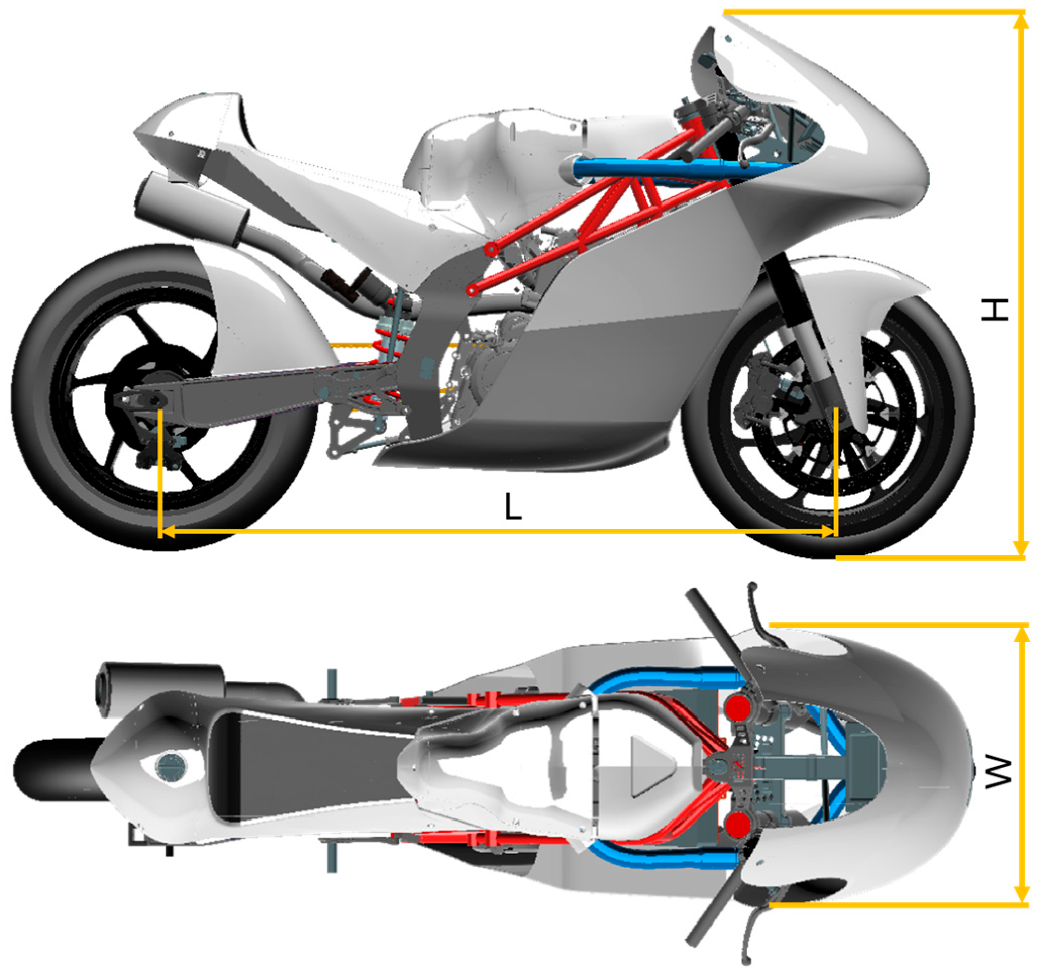
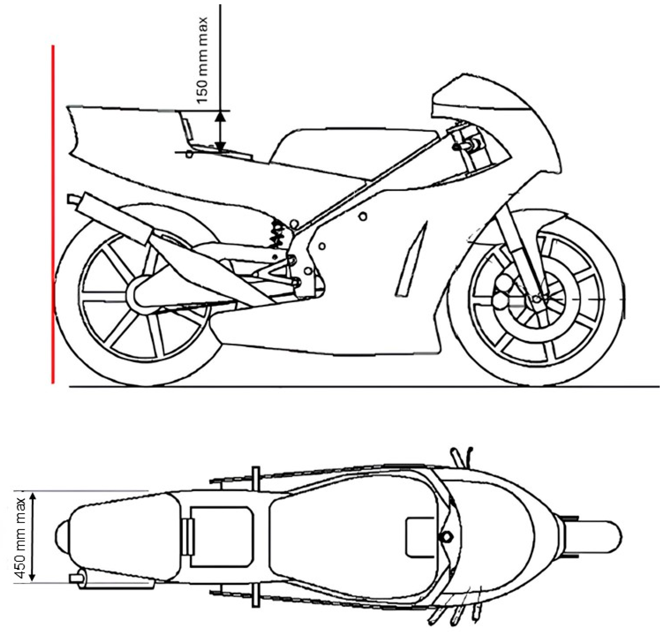
The prototype under investigation is a 250 cc Pre-Moto3 racing motorcycle, specifically developed for participation in the VII MotoStudent International Competition. This prototype represents a comprehensive engineering effort, as several components were conceptualized, designed, and manufactured entirely from scratch. The only fundamental constraint guiding the design process was full compliance with the competition regulations, which imposed specific limits on dimensions and geometrical arrangements. In particular, the design of the rear fairing was subject to well-defined geometric constraints. These included a maximum allowable distance of 150 mm between the seat and the highest point of the rear fairing, as well as a maximum width restriction of 450 mm. Adherence to these limitations was crucial not only for regulatory compliance but also to ensure optimal aerodynamic performance and maintain the overall balance and packaging of the motorcycle. A graphical summary of the initial design and key features is presented in Figure 1.
The finalized geometries of the motorcycle are illustrated in Figure 2, where the three principal dimensions of the prototype (length, width, and height) are explicitly indicated. These dimensions will serve as reference points in the subsequent analysis and discussion.
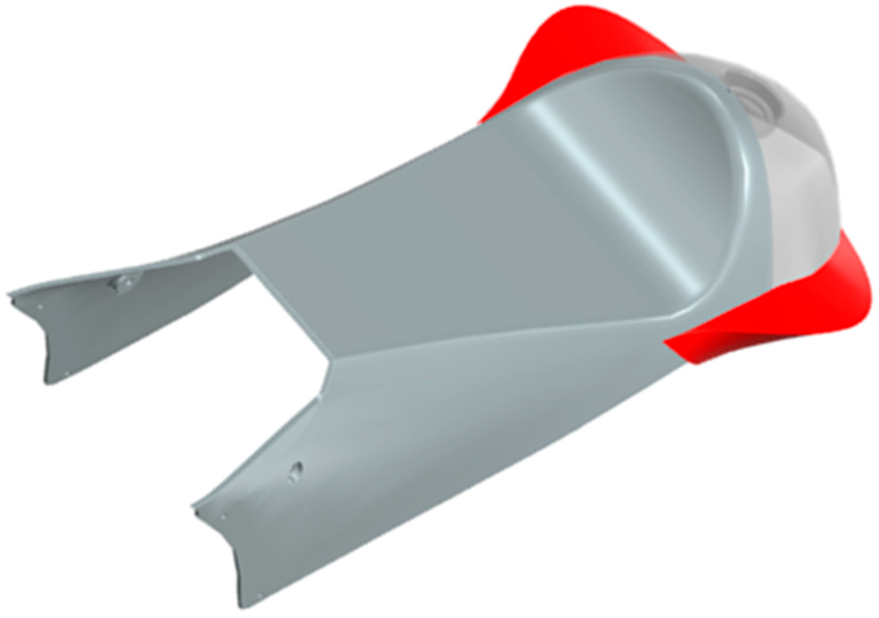
To enhance the aerodynamic characteristics, particularly the wake closure behind the rider and tail section, an initial experimental design of rear winglets was developed. This first iteration aimed to evaluate the effects on flow separation and drag reduction, while still respecting the overall spatial envelope imposed by the competition rules. The winglets are designed to be symmetrically mounted on both the left and right sides of the tail section, and their precise dimensions are reported in Figure 3.
Figure 4 illustrates the application of the two rear winglets mounted on the tail section.
The current winglet configuration serves as the baseline geometry for a more comprehensive aerodynamic evaluation, which will be systematically described in the following section.

2.2. CFD Setup

The CFD model was developed using Simcenter STAR-CCM+ 2310, within which the complete geometry of the motorcycle-rider assembly was imported.

2.2.1. Computational Domain

The setup of the simulation, with only minor adjustments, follows the configuration previously validated in [25] for motorcycles of similar dimensions and tested at the same velocity. The validation with the current prototype is reported in Appendix A.1. The computational domain was generated using a Boolean subtraction between a rectangular block and the motorcycle-rider assembly, ensuring that the flow field accurately envelops the entire geometry. The overall length of the domain is 8L, with a distance of 2L between the velocity inlet and the motorcycle, and 5L between the motorcycle and the Pressure Outlet. The domain height is set to 2H, while the depth extends to 7W, providing sufficient space to minimize blockage effects and ensure accurate wake development.
The Velocity Inlets are defined with a uniform flow of 160 km/h along the x-direction, as illustrated in Figure 5. This setup allows the simulation to reproduce realistic on-track conditions and provides a consistent basis for comparing aerodynamic performance across different configurations of the prototype. The numerical solution was obtained by exploiting the symmetry of the problem, defining a Symmetry boundary condition. The resulting scenes were then mirrored to reconstruct the full physical domain for visualization purposes.
The pressure and density values used in the simulations are those specified in Table 1.
In addition to the previously mentioned boundary conditions, walls are also defined to represent the ground, the motorcycle including all its components, and the rider. These wall boundaries are essential for accurately capturing the no-slip condition at solid surfaces, which strongly influences the development of the boundary layer, the formation of vortices, and the overall aerodynamic behaviour of the motorcycle-rider system.

2.2.2. Mesh and Physics Models

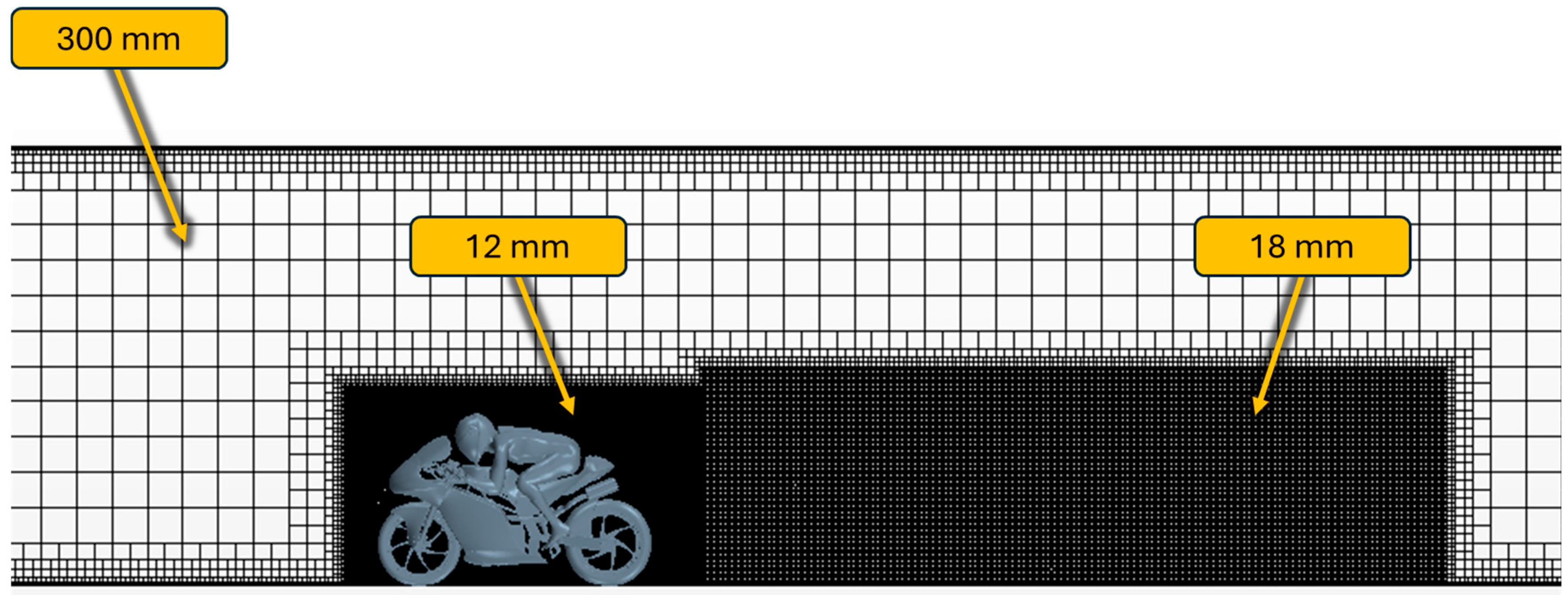
The control volume was meshed using a trimmed cell mesher, which provides flexibility in capturing complex geometries while maintaining mesh quality (Figure 6). The transition between the outer domain cells and the surface of the motorcycle was achieved using a prism layer mesher, allowing for accurate resolution of the boundary layer and near-wall flow phenomena. The first layer of cells in contact with the motorcycle surface has a thickness of 0.1 mm, and the mesh grows through eight successive prism layers until reaching the cell size of the Motorcycle Refinement Block, which is 12 mm. The background mesh can go up to 300 mm, while the Wake Refinement Block is discretized with a finer resolution of 18 mm to accurately capture wake structures and vortex shedding behind the motorcycle.
In the baseline simulation without tail winglets, the total mesh consists of 20,737,041 cells. This high-resolution mesh ensures sufficient detail to resolve critical aerodynamic features while maintaining computational efficiency.
The turbulence model selected for this study is the Realizable Two-Layer k-ε model, which has been shown to provide a good balance between accuracy and computational efficiency for external aerodynamic flows around complex geometries [26,27]. The simulations were performed under steady-state conditions, allowing for the evaluation of the mean flow field and the aerodynamic forces acting on the motorcycle-rider assembly.
A summary of the primary physics models and numerical settings employed in the simulations is presented in Table 2.
Among the quantities that will be evaluated, in addition to lift, drag, and their ratio, are the pressure, the Wall Shear Stress (WSS), and the Turbulent Kinetic Energy (TKE).
The Wall Shear Stress represents the tangential stress exerted by the fluid on the wall surface due to viscosity (Equation (1)). It quantifies the frictional interaction between the moving fluid and the solid boundary.
τ w = μ u y y = 0
In Equation (1), τ w is the Wall Shear Stress [Pa] and μ the dynamic viscosity of the fluid [Pa·s] (defined in Equation (2)).
u y y = 0
The Turbulent Kinetic Energy measures the intensity of turbulence in the flow, essentially the mean kinetic energy per unit mass associated with velocity fluctuations (Equation (3)).
k = 1 2 ( u 2 + v 2 + w 2 )
In Equation (3), k is turbulent kinetic energy [m2/s2], u , v , w the velocity fluctuations in the x, y, and z directions and with the overbar is indicated an average.

2.3. Design Space Exploration Workflow

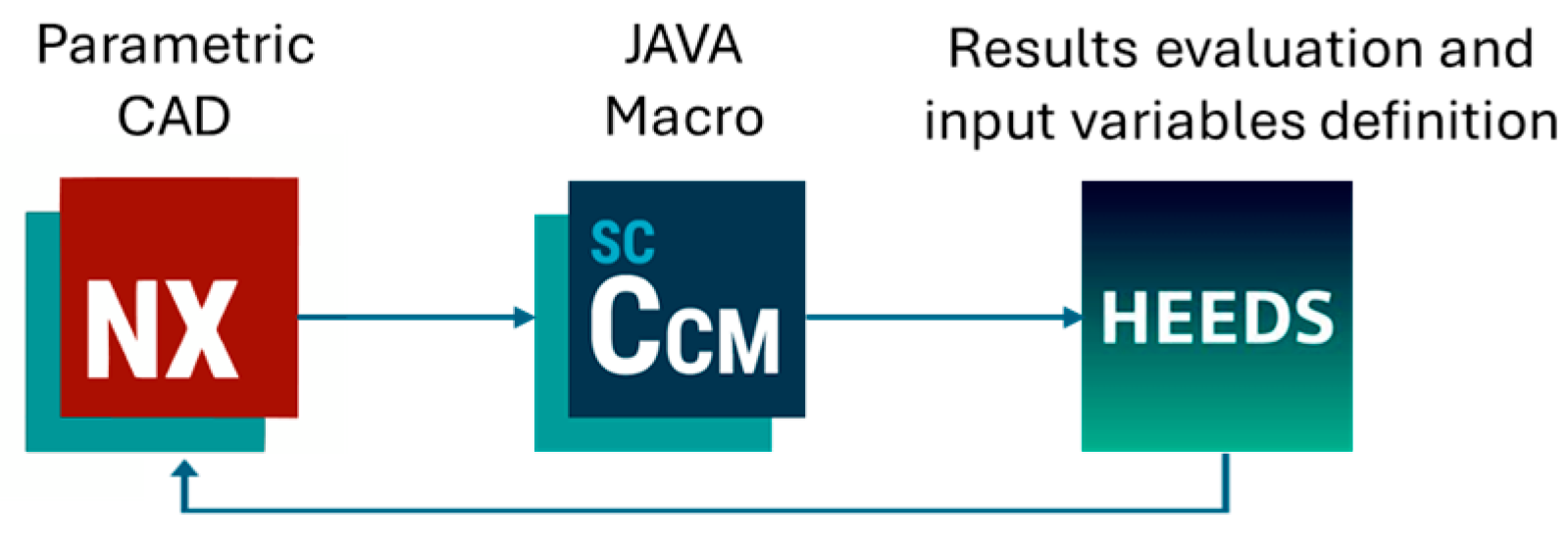
The evaluation cycle is part of a Design Space Exploration (DSE) process, aimed at systematically exploring different geometric configurations of the component to optimize its performance. At each iteration, HEEDS defines the construction parameters of the model. Based on these parameters, NX generates the rear winglet model and exports it in a format compatible with STAR-CCM+. A Java macro within STAR-CCM+ then imports the geometry, positions it within the CFD domain, generates the mesh, and computes the aerodynamic loads.
The resulting data are collected by HEEDS, which updates the construction parameters and initiates the next iteration. The optimization process leverages the SHERPA method, a guided exploration strategy that combines global and local approaches to efficiently identify optimal configurations within the design space, balancing computational cost and result accuracy. A schematic representation of this workflow is provided in Figure 7.
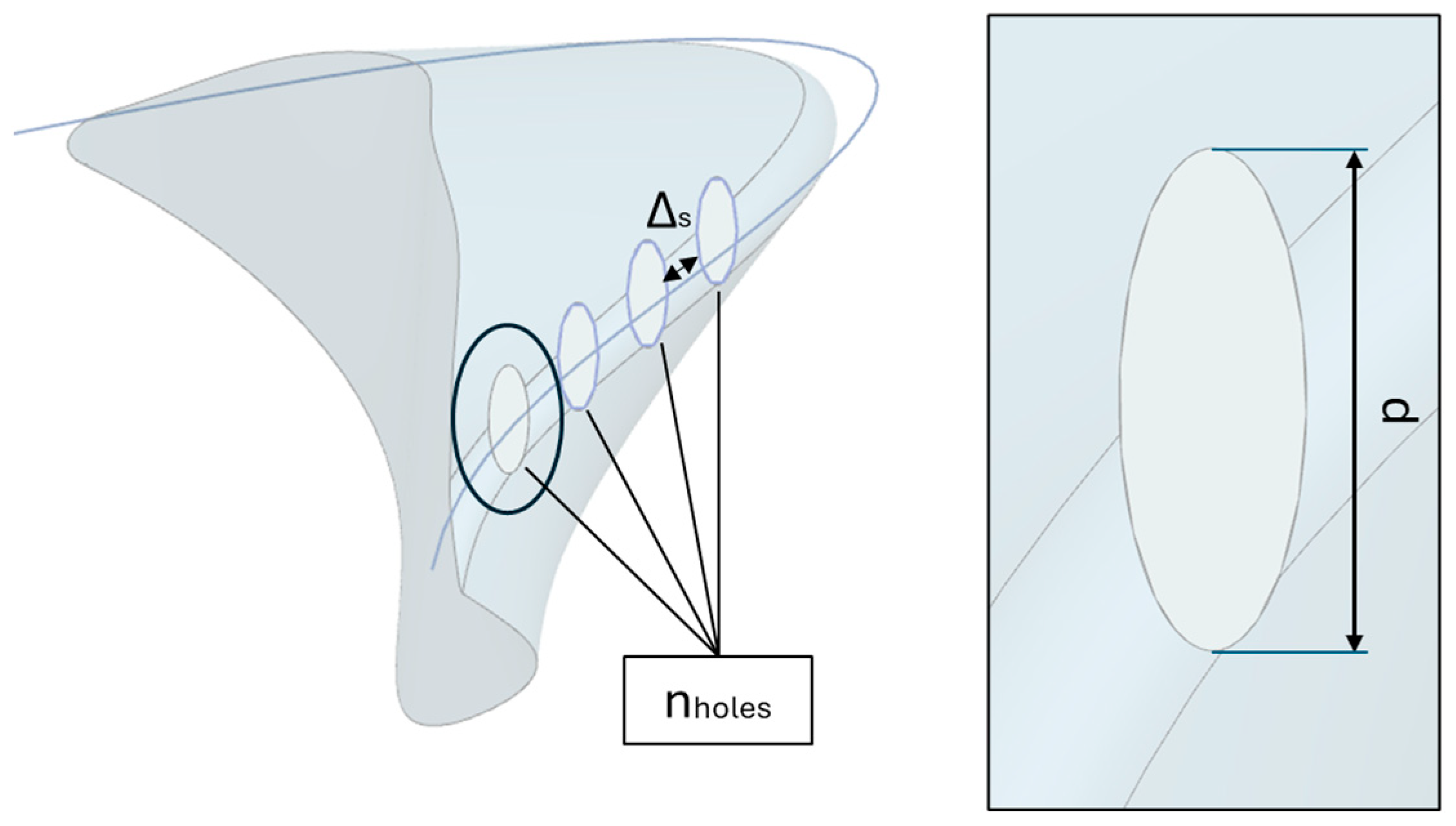
In order to define the evaluation process, the rear winglet model in NX was modified using parameterized Boolean subtractions. This approach allows the design to be adjusted iteratively with the goal of reducing aerodynamic drag while maximizing downforce. The CAD model parameters, which serve as the variables in the evaluation, are illustrated in Figure 8.
The used parameters consist of three variables: the number of holes ( n holes ), the spacing between the holes ( Δ s ), which can be distributed evenly along a curvilinear guide, and the vertical dimension ( p ) of the base ellipse used to generate the extrusion for the Boolean subtraction. The defined objective of the DSE is the reduction in the drag generated by the winglets.
The selection of the number and spacing of holes for the rear winglet is guided by core aerodynamic mechanisms, specifically airflow extraction and pressure relief in the tail region. Increasing the number of holes and adjusting their spacing creates multiple flow paths, which facilitate local pressure reduction and enhance wake dissipation by allowing high-energy airflow to escape from zones of stagnation behind the appendage. This extraction effect is key to reducing adverse pressure gradients that promote flow separation and turbulent kinetic energy, contributing to improved wake closure and lower drag. Close spacing of holes, distributed along a curvilinear guide, is engineered to maximize pressure equalization and to break up large recirculation zones. By varying hole count and position, the design can tune the interaction between winglet surface shear and the surrounding flow, promoting more uniform load distribution and improved aerodynamic stability.
This design strategy mirrors airflow management solutions found in motorsport and automotive engineering, such as diffusers, louvers, and vented bodywork, where controlled perforations are used for energy extraction and pressure balance without significantly increasing aerodynamic resistance. The parametric Design Space Exploration framework enables systematic identification of optimal combinations of hole number and spacing, balancing manufacturing constraints with aerodynamic performance targets.
Once the basic shape is defined, the subtraction is performed. Figure 9 shows a snapshot of the model after extruding the base shapes but prior to executing the Boolean subtraction.
The parameters naturally have upper and lower bounds determined by the manufacturability of the final shape. These limits are reported in Table 3.

3. Results and Discussions

The results of the CFD simulations for the various configurations are presented in this chapter. The first configuration tested, serving as a reference, is the motorcycle without any rear winglets. The data related to the aerodynamic forces measured on the entire prototype are reported in Table 4.
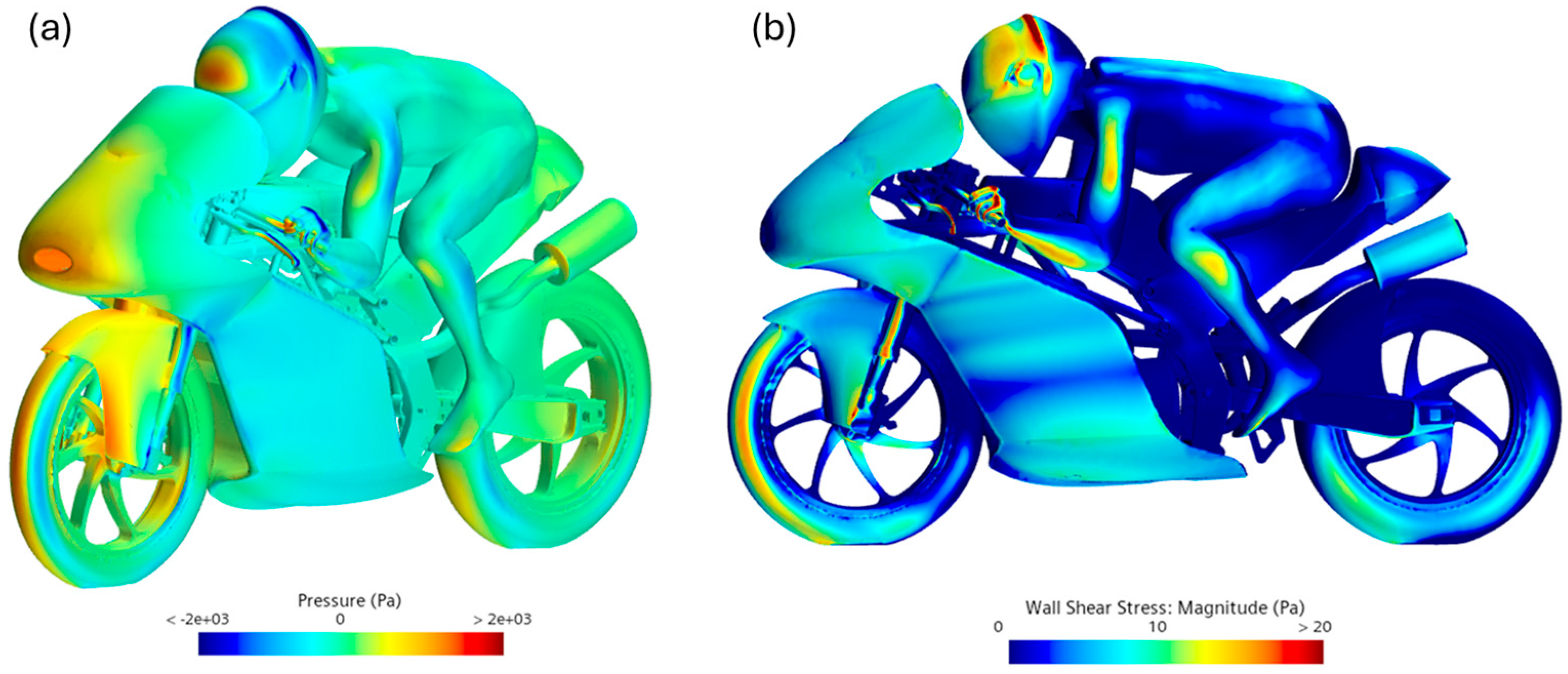
In addition to numerical values, the focus of the evaluation also included the analysis of scalar fields of pressure and wall shear stress magnitude, as shown in Figure 10.
Figure 10a shows the pressure distribution. Notably, there are regions of high pressure across the front tyre tread, the front fairing, and the rider’s helmet. The most significant low-pressure regions, where the flow is accelerated, are located at the rear of the forks and behind the rider’s helmet. Figure 10b, on the other hand, illustrates the magnitude of the wall shear stress vector, which indicates how the flow distributes over the motorcycle-rider assembly. Areas with high wall shear correspond to attached flow and good aerodynamic penetration, whereas low values indicate flow separation, which can signal wake regions and increased turbulence. From this perspective, it is evident that the tail section, positioned behind various components, is located in a flow separation zone.
The second simulation was conducted with the baseline rear winglets. The resulting primary aerodynamic coefficients are reported in Table 5.
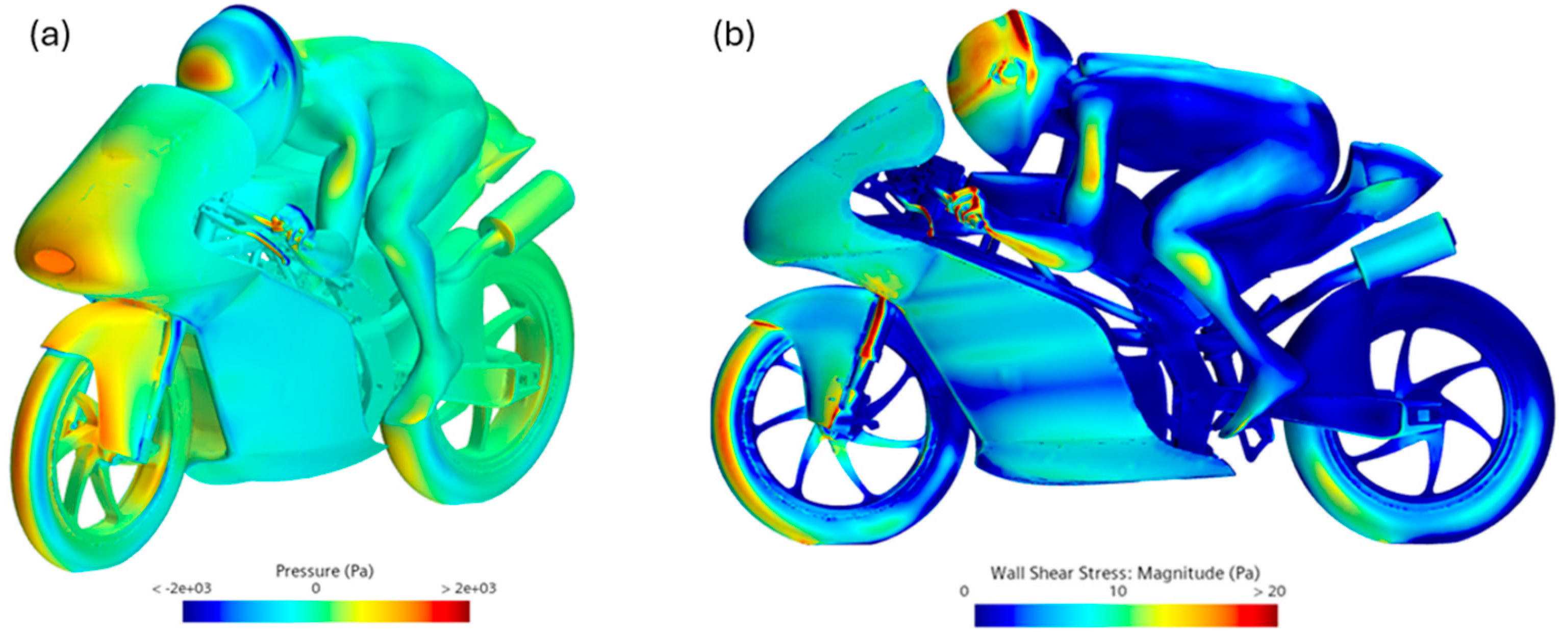
The drag has slightly increased compared to the case without winglets; however, the motorcycle, which previously generated a total lift of 5 N, now produces a total, albeit localized, downforce of 1.41 N. This represents a positive outcome, although it is partially offset by the slight increase in drag. Figure 11 shows the corresponding pressure and wall shear stress fields.
The local modification introduced by the addition of the winglets clearly does not significantly affect the two global fields. In Figure 11a, a slight increase in pressure is observed on the rear winglet, which can be associated with the recorded increase in drag. Figure 11b shows that the winglets have increased the wall shear stress in the tail section area, indicating that they are capturing the flow and generating downforce.
At this stage, the evaluation of different winglet shapes was initiated to assess their impact on the prototype’s performance. The objective is to monitor the drag generated by the winglet alone in order to quantify its contribution to the overall design variations.
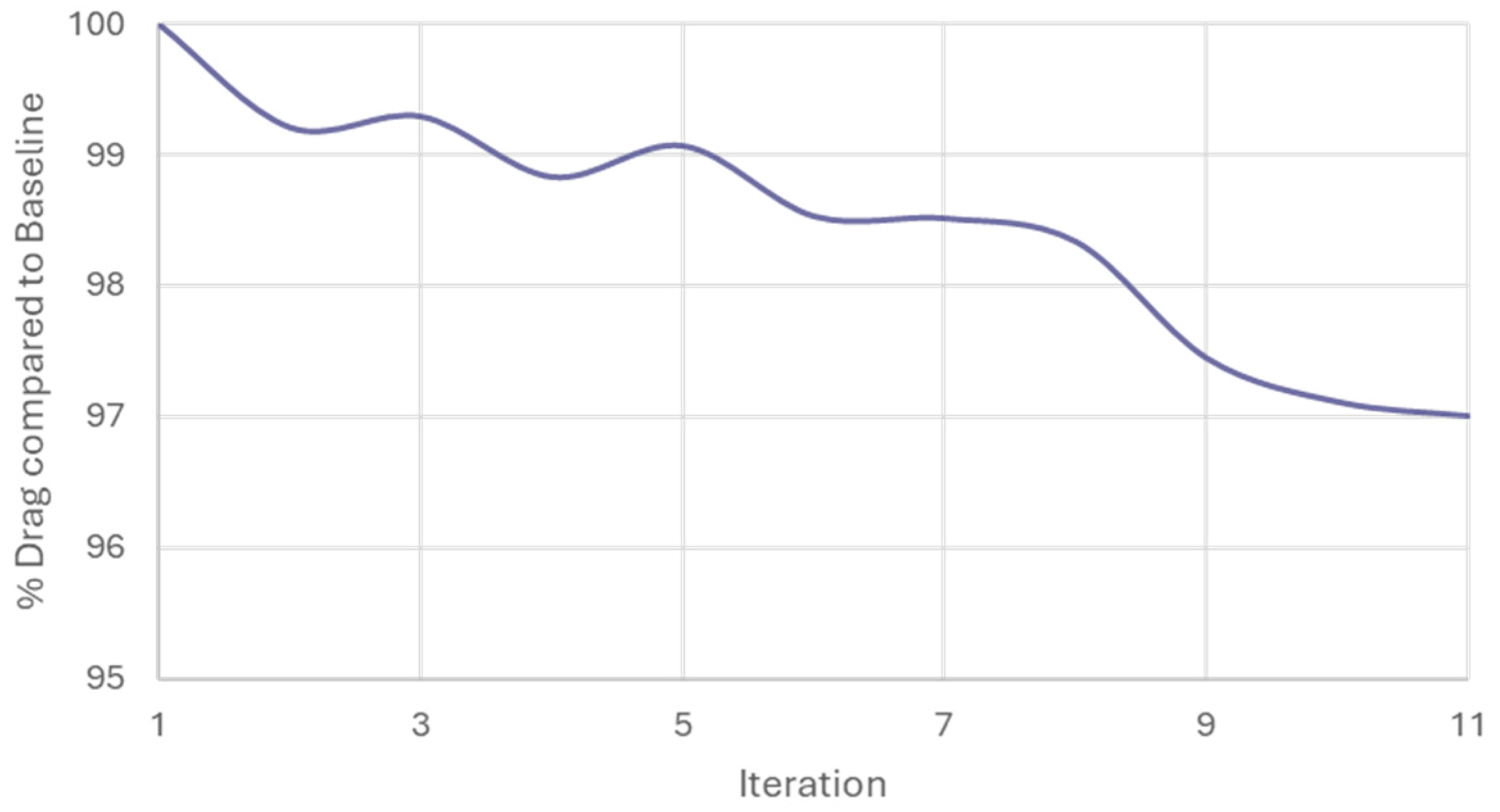
Figure 12 shows the trend of drag variation for a single winglet as its design is modified. The first value, assigned as 100%, corresponds to the initially evaluated perforated design. Subsequent values are expressed as percentages relative to this first design.
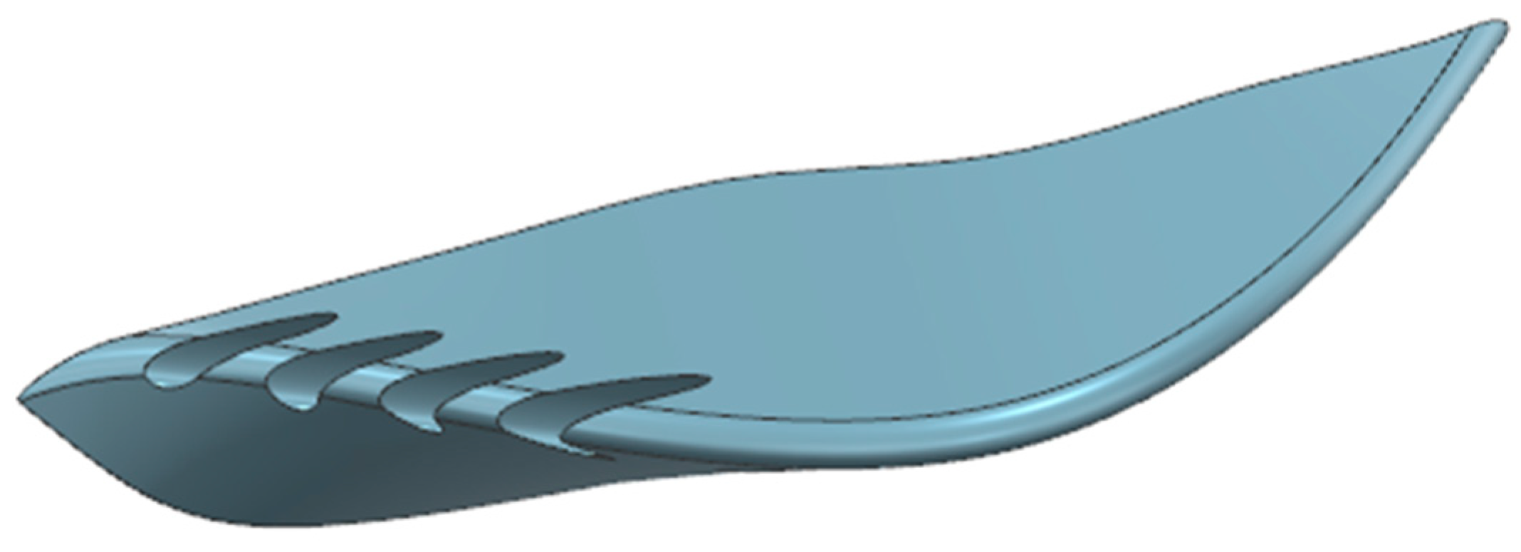
The design obtained at the end of the evaluation cycle, namely the eleventh iteration, is shown in Figure 13.
In Table 6 the drag variation and the parameters set by HEEDS during its evaluation cycle are listed for each Design ID.
In Table 7 the new global values related to the prototype with fins ID 11 are reported.
Following a decrease in drag, the prototype has now returned to a condition of slight lift compared to the case with solid winglets. It is important to note, however, that this value remains significantly lower than that of the prototype without winglets. Although the absolute variation between the first and the last configuration is 3.4 N, a reduction of about 63% in lift is obtained and such variations, despite their small absolute magnitude, can significantly influence the pitch balance and dynamic stability of the motorcycle during high-speed operation.
Even small aerodynamic load variations can influence the pitch equilibrium of a lightweight racing motorcycle, where total aerodynamic forces are comparable to the static load transfer induced by acceleration or braking. The generation of additional rear downforce, even in the range of a few Newtons, contributes to improved rear wheel traction and mitigates the tendency to wheelie during strong acceleration phases. Conversely, the reduction in front-end lift enhances directional stability and rider control at high speed.
Moreover, the observed decrease in drag, though limited in absolute terms, indicates a more favourable pressure recovery and wake closure, which can improve flow attachment and reduce unsteady aerodynamic oscillations acting on the rear section.
Therefore, while the numerical differences in drag and lift coefficients may appear relatively small, their combined aerodynamic effects can substantially enhance the balance and controllability of the motorcycle, especially in competition scenarios where stability margins are inherently tight and rider feedback is highly sensitive to minor aerodynamic variations.
As done previously, the analysis was not limited to numerical evaluation alone; the pressure and WSS fields were once again extracted for further examination.
Figure 14a clearly shows, as expected, that perforating the winglet has created escape channels for the airflow. Consequently, this region now exhibits reduced pressure compared to Figure 14b. Additionally, Figure 14b demonstrates an increase in WSS magnitude in the tail section area. This indicates that the channels are effectively functioning as flow extractors, enhancing the interaction with the surrounding airflow.
This behaviour is consistent with what has been observed in automotive and motorsport applications, where flow extractors, such as diffuser channels, hood vents, or small aerodynamic louvers, are used to redirect airflow, improve pressure distribution, and enhance downforce without significantly increasing drag.
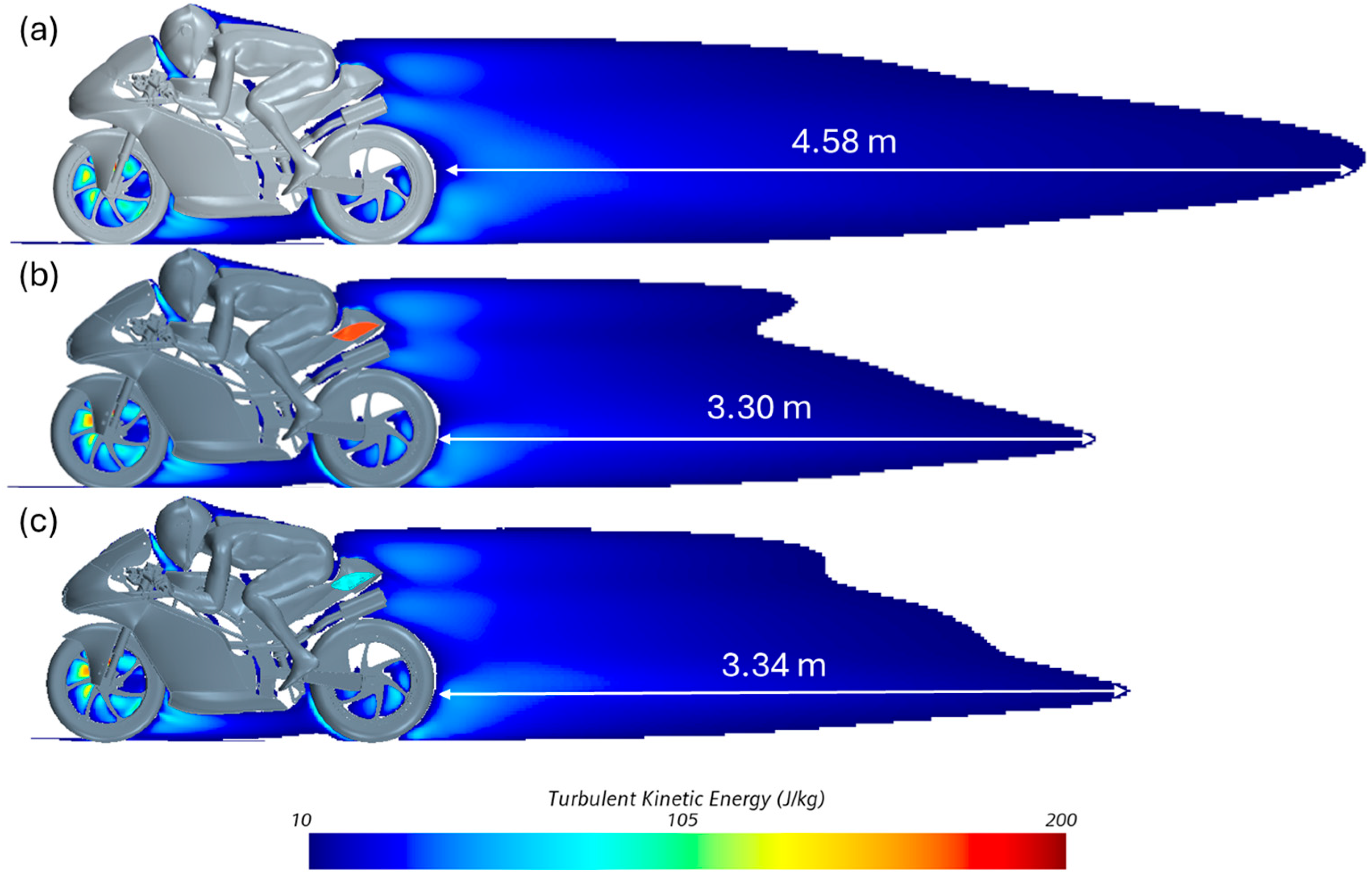
Finally, to conclude the analysis, the turbulent kinetic energy (TKE) within the computational domain was examined. The comparison between the case without winglets, with solid winglets, and with Design ID 11 winglets is shown in Figure 15.
Figure 15a represents the case without winglets, Figure 15b shows the case with the baseline winglets, and Figure 15c corresponds to the case with the final winglets obtained from the evaluation cycle. In all plots, TKE values below 10 were clipped, as values under this threshold are considered indicative of an essentially dissipated wake energy.
Additionally, the distance at which the wake dissipates was calculated. The results show that the baseline wake length has been significantly reduced, with reductions of 1.28 m and 1.32 m for the cases with full and baseline winglets, respectively. These findings confirm that Design ID 11 represents an effective compromise between different aerodynamic characteristics considered in the evaluation.
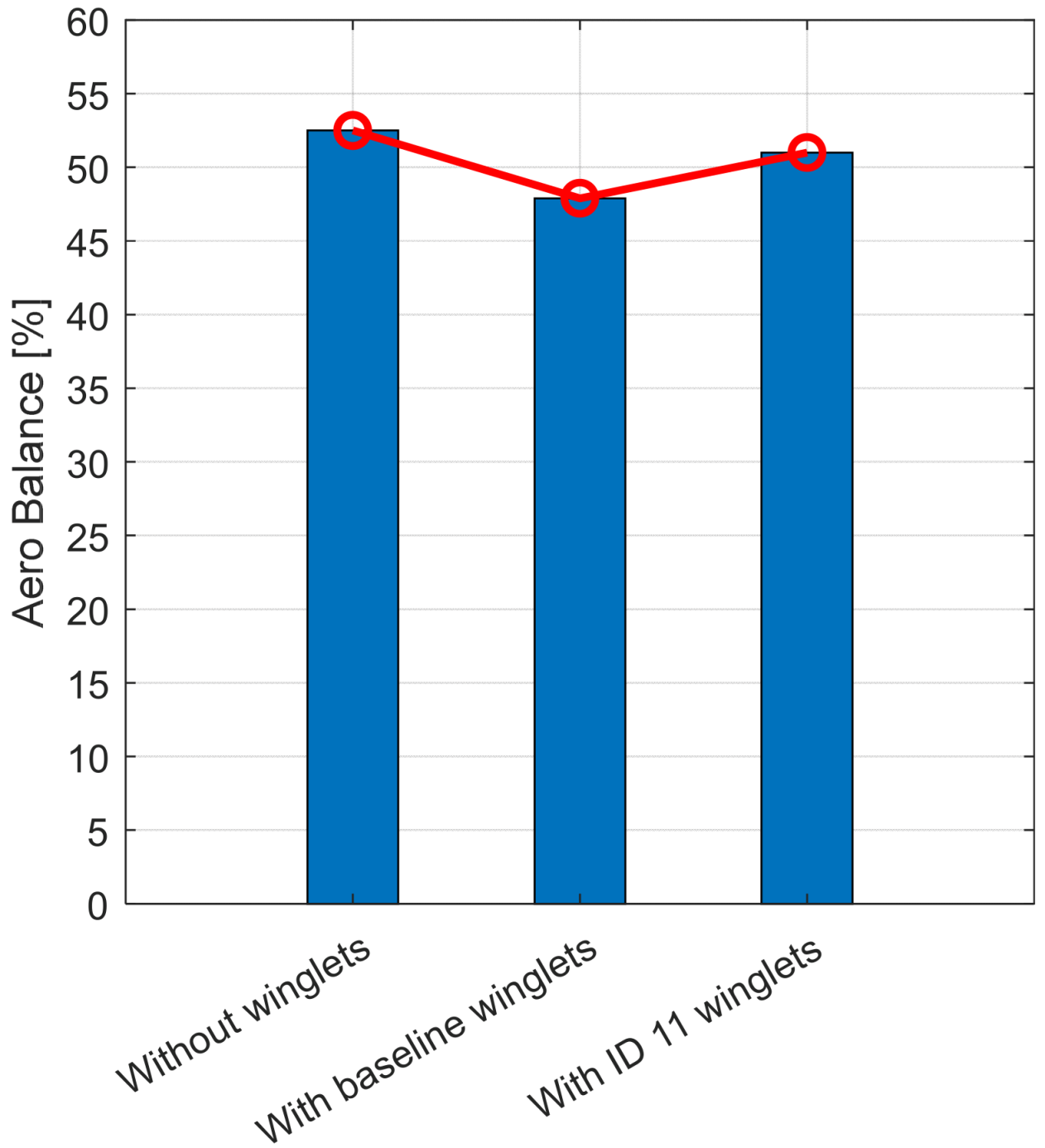
To deepen the analysis of how the winglets shape the aerodynamic behaviour of the motorcycle, the aero balance was evaluated as a compact and physically meaningful indicator of how aerodynamic load is distributed between the front and rear axles. Aero balance AB can be defined as in Equation (4).
A B = F f r o n t F f r o n t + F r e a r · 100 %
This formulation expresses the front load fraction relative to the total vertical aerodynamic force. The results are in Table 8.
Without winglets, the computed balance indicated a front-heavy condition, consistent with a forward-shifted aerodynamic centre that can amplify oversteer tendencies and increase sensitivity to pitch during braking and turn-in. Introducing the baseline winglets shifted the balance rearward, alleviating the front overload by redistributing the aerodynamic forces and nudging the resultant closer to a more stable position over the wheelbase as speed and attitude vary, yet an overly rear-biased aero balance is undesirable, as it reduces anti-wheelie authority at the front and can encourage front-wheel lift under throttle. With the ID 11 winglets the aero balance approached a neutral value (≈50%), aligning with design practice that targets a centre of aerodynamic pressure near the centre of gravity to minimize handling asymmetries across operating conditions. The AB values are charted in Figure 16.
In motorcycle engineering specifically, a neutral aero balance is sought for the combined prototype–rider system to limit pitch-induced load migration, stabilize acceleration and braking, and enhance overall rideability as modern appendages generate controllable downforce within regulatory constraints.

4. Conclusions

This study systematically evaluated the aerodynamic influence of rear fairing winglets on a 250 cc Pre-Moto3 racing motorcycle prototype, providing an integrated assessment of their effects on drag, downforce, wake characteristics, and overall stability. The analysis demonstrated that rear aerodynamic appendages can significantly affect the flow behaviour around the motorcycle–rider system, highlighting their potential as performance enhancing elements in racing motorcycle design.
A parametric, multi-software Design Space Exploration (DSE) framework was employed, combining parametric modelling in Siemens NX, automated geometry handling and meshing in Simcenter STAR-CCM+, and iterative optimization via HEEDS using the SHERPA algorithm. This methodology proved effective for systematically evaluating the aerodynamic response of multiple rear winglet geometries, while maintaining high computational efficiency. Design variables such as the number and spacing of perforations and the vertical extension of the winglet base were optimized within realistic manufacturing and regulatory limits.
The baseline configuration, without any rear winglets, established a reference aerodynamic condition at a velocity of 160 km/h. Under these conditions, the motorcycle prototype exhibited a drag force of 226.91 N and a small net lift of 5.34 N, corresponding to a lift-to-drag ratio of 0.0235. Pressure and wall shear stress (WSS) analyses revealed that high-pressure regions were concentrated around the front tire tread, the frontal fairing, and the rider’s helmet, whereas low-pressure zones formed behind the forks and the rider’s head. These low-pressure areas indicated flow separation and recirculation zones, particularly around the tail, confirming the rear section as a critical source of aerodynamic inefficiency and instability.
Introducing baseline rear winglets resulted in measurable aerodynamic changes. Although drag slightly increased from 226.91 N to 228.47 N, the net lift was reduced from 5.34 N to −1.41 N, yielding a lift-to-drag ratio of −0.0062. This indicates that the winglets effectively generated downforce while only marginally increasing drag. The pressure field displayed moderate localized pressure increments on the winglet surfaces, consistent with the drag rise, whereas WSS distributions revealed improved flow attachment and reduced recirculation near the tail. These findings confirm that even simple rear aerodynamic devices can positively influence downforce and wake management, which are key factors in improving rear tire grip and high-speed stability. However, the observed drag increase highlights the inherent trade-off between achieving additional downforce and maintaining low aerodynamic resistance.
A systematic parametric evaluation was then carried out to assess how geometric variations influence aerodynamic performance. Eleven design iterations were performed, varying the number of holes, their spacing, and the winglet base extrusion within defined design boundaries. By isolating the drag contribution of the winglet itself, the analysis clarified the aerodynamic effects of individual design parameters. The optimized configuration, identified as Winglets ID 11, achieved a total drag force of 226.69 N, almost matching the baseline drag of the configuration without winglets, while simultaneously generating a net downforce of 1.94 N. This resulted in a lift-to-drag ratio of 0.0086, representing a favorable compromise between drag reduction and downforce generation.
Detailed flow visualization confirmed that the perforations introduced in the optimized winglets acted as effective flow extractors. WSS distributions showed increased shear stress in the tail section, indicating more controlled flow detachment, while pressure fields exhibited local relief near the perforations, leading to reduced overall drag compared with the solid-winglet baseline. This behaviour aligns with aerodynamic strategies employed in diffusers, hood vents, and louvers, where controlled flow passages allow wake management without excessive resistance.
Analysis of turbulent kinetic energy (TKE) further supported these findings. The wake length behind the motorcycle was reduced by up to 1.32 m for Winglets ID 11 compared with the baseline, confirming that the optimized design improved wake closure and turbulence dissipation. The resulting reduction in turbulent energy implies a smoother aerodynamic environment for trailing vehicles and potentially improved stability during high-speed maneuvers. This effect is particularly relevant in racing contexts, where reduced wake intensity can limit the slipstream advantage of following competitors and enhance predictability in acceleration and cornering phases.
Overall, the results highlight the value of integrating parametric modelling, automated CFD analysis, and optimization algorithms in the aerodynamic development of racing motorcycles. The adopted SHERPA-guided DSE approach effectively balanced global and local optimization goals, identifying configurations that reconcile the conflicting requirements of drag minimization and downforce enhancement. The demonstrated capability to automate complex design evaluations with minimal human input underscores the efficiency and robustness of this workflow for high-performance engineering applications.
From a broader aerodynamic perspective, this investigation contributes to the understanding of rear fairing winglets, a class of appendages less studied than front or side devices. While front-mounted components primarily manage front-end lift and directional stability, rear winglets directly affect rear-tire loading, pitch control, and wake structure. The present results confirm that even modest geometric modifications, such as introducing perforations or adjusting vertical dimensions, can yield measurable improvements in aerodynamic efficiency and stability, outcomes that are especially relevant in performance-sensitive categories.
Dynamic effects such as rider motion, crosswinds, and transient yaw or pitch variations were not captured, nor were wheel rotation and detailed road interactions. All these aspects could be incorporated in future work. Extending the current DSE framework toward advanced optimization schemes, such as genetic algorithms or surrogate-based multi-objective strategies, would further enable comprehensive aerodynamic trade-off analysis under transient or variable conditions. Such developments could support a more holistic aerodynamic optimization process, aimed at optimizing rear downforce, minimizing drag, and controlling wake turbulence for improved performance in competitive racing environments.
Author Contributions

Conceptualization, M.C. and F.C.; methodology, M.C. and F.C.; software, M.C. and A.C.; validation, M.C.; formal analysis, F.C. and G.R.; investigation, F.C.; data curation, E.B., and A.C.; writing—original draft preparation, A.C. and M.C.; writing—review and editing, E.B. and M.C.; visualization, M.C.; supervision, F.C. and G.R. All authors have read and agreed to the published version of the manuscript.

Funding

This research received no external funding.

Institutional Review Board Statement

Not applicable.

Informed Consent Statement

Not applicable.

Data Availability Statement

The raw data supporting the conclusions of this article will be made available by the authors on request.

Acknowledgments

The authors would like to thank the Motostudent team of the University of Messina, “Stretto in Carena UNIME”, and Dario Milone, for providing the opportunity to present the data in this article.

Conflicts of Interest

Author Alessandro Caristi is employed by Pirelli Tyre s.p.a. The company had no role in the design of the study; in the collection, analyses, or interpretation of data; in the writing of the manuscript, and in the decision to publish the results. The other authors have no conflicts of interest.

Appendix A

Appendix A.1. Wind Tunnel Validation

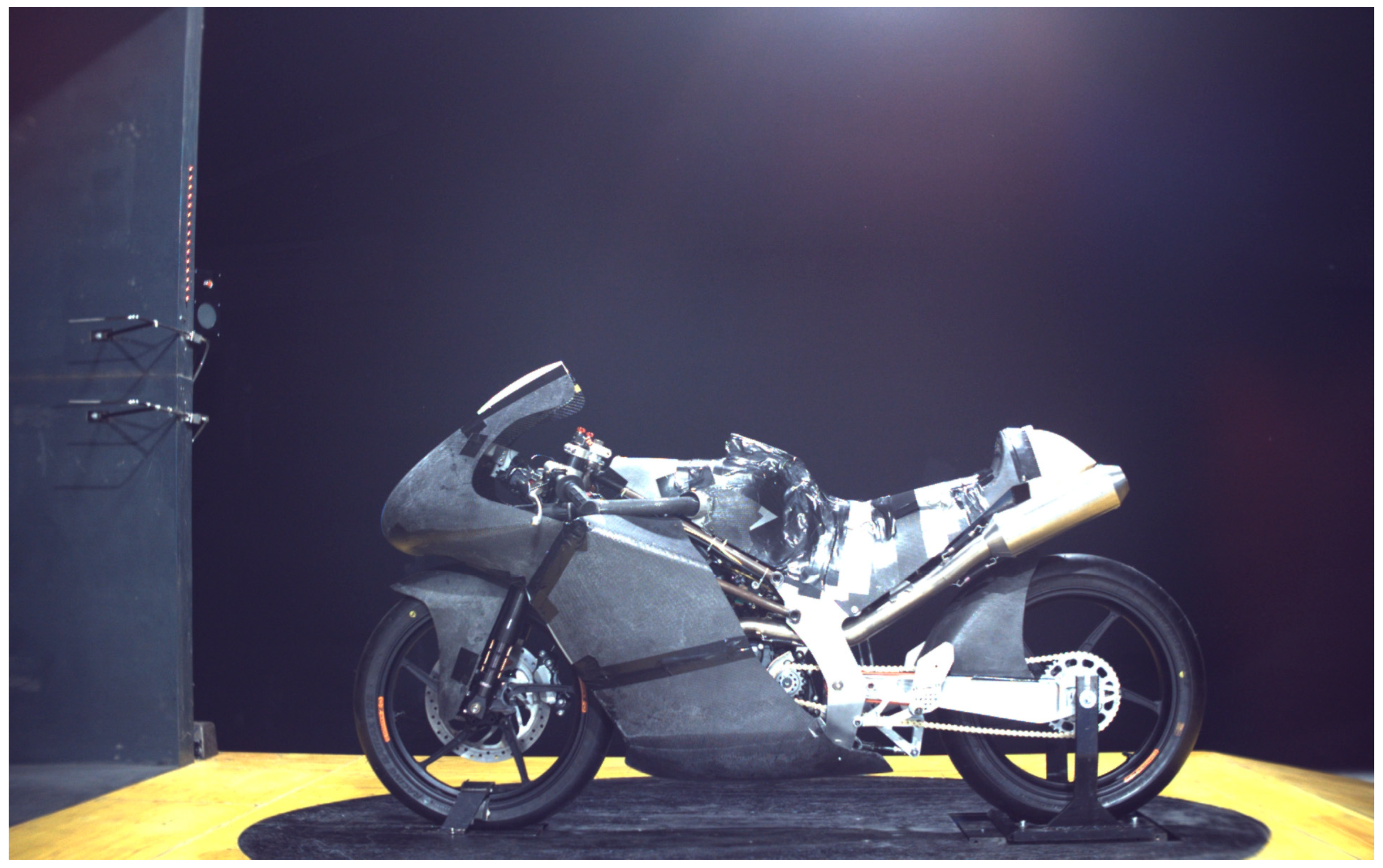
Wind tunnel tests of the prototype without aerodynamic appendages were carried out at the Raffaele Balli Wind Tunnel of the University of Perugia. The riderless prototype was tested under the same conditions as the CFD model presented in this paper, with a cover in the low fairing to shield the heat exchanger. The results of the wind tunnel campaign were then directly compared with those of the corresponding CFD simulation, showing discrepancies in terms of drag, lift, and CD⋅A. The CFD model used for validation is the same as that presented in Chapter 2 of the paper, except that the rider has been removed.
The experimental setup is represented in Figure A1.
Figure A1. Prototype without rider and appendages in the wind tunnel.
Applsci 15 12064 g0a1
The comparison is listed in Table A1.
Table A1. Comparison between experimental and numerical results.
Drag [N]Lift [N]CD·A
EXP275.522−19.6230.235
CFD276.811−20.0810.242
% Diff.0.464−2.2752.849
The drag results for the riderless prototype are naturally higher, since the presence of a rider reduces resistance by preventing recirculation behind the windscreen and seat. Similarly, the rider influences lift, tending to raise the motorcycle due to aerodynamic forces. Nevertheless, the results for drag, lift, and CD·A are comparable, showing differences well below 3% between experimental and numerical values. Therefore, the CFD model can be considered validated and suitable as a basis for further assessments, including the addition of a rider, aerodynamic appendages, and subsequent performance evaluations.

Appendix A.2. Sensitivity Analysis

To further consolidate the credibility of the CFD model, beyond the already satisfactory comparison with the wind tunnel measurements, a mesh sensitivity analysis was performed using the Richardson extrapolation technique. This approach provides a quantitative assessment of the influence of grid resolution on the computed solution, yielding a consistent estimation of the discretization error and confirming grid independence and numerical reliability of the aerodynamic results.
To quantify the numerical uncertainty of the simulations, the procedure followed the methodology recommended by the ITTC (2017) [28]. Several sources of numerical uncertainty can affect CFD simulations, the most relevant being: iterative errors ( U I ), grid-spacing errors ( U G ), and time-step errors ( U T ). As discussed by Stern et al. in [29], the grid-related contribution generally dominates, often by one order of magnitude, and is therefore the primary focus in verification studies. The adopted approach consisted of running the same CFD setup on three systematically refined meshes (coarse, medium, and fine) with a constant refinement ratio r . Differences between successive grid levels were then analyzed to determine the order of convergence and the discretization uncertainty.
Richardson extrapolation accelerates convergence by cancelling the leading discretization-error term in the asymptotic expansion as the grid spacing h 0 (Equation (A1)).
ϕ ( h ) = ϕ + C h p + O ( h p + 1 )
In numerical verification, the Grid Convergence Index (GCI) expresses a conservative percentage estimate of the discretization uncertainty between adjacent grid levels, based on the observed order of convergence and a prescribed safety factor.
The procedure considers three geometrically similar grids of characteristic sizes h 1 < h 2 < h 3 with a constant refinement ratio (Equation (A2)).
r = h 2 h 1 = h 3 h 2 = 2
The grids produce corresponding numerical solutions ϕ 1 , ϕ 2 , and ϕ 3 on the fine, medium, and coarse meshes. Assuming that the dominant truncation error scales with h p , the three-grid sequence is expected to lie in the asymptotic range, where higher-order terms are negligible.
The apparent order of accuracy is obtained from the three solutions as in Equation (A3).
p = l n ( ϕ 3 ϕ 2 ϕ 2 ϕ 1 ) l n ( r )
This formulation is valid only under monotonic convergence, i.e., when ( ϕ 3 ϕ 2 ) ( ϕ 2 ϕ 1 ) > 0 .
The successive differences are defined in Equations (A4) and (A5).
ε 21 = ϕ 2 ϕ 1
ε 32 = ϕ 3 ϕ 2
The convergence ratio is expressed as in Equation (A6).
R G = ε 21 ε 32
The convergence ratio value classifies the convergence behavior as in Table A2.
Table A2. Convergence ratio interpretation.
Convergence Ratio R G Interpretation
0 < R G < 1 Monotonic convergence
R G < 0 Oscillatory convergence
R G > 1 Divergence
Given the apparent order p and refinement ratio r , the two-level Richardson extrapolation based on the fine–medium pair provides the asymptotic solution as in Equation (A7).
ϕ = ϕ 1 + ϕ 1 ϕ 2 r p 1
Equation (A7) eliminates the leading-order discretization-error term and yields a higher-order estimate of the grid-independent value.
For two successive grid pairs, the GCI is computed as a conservative percentage uncertainty (Equations (A8) and (A9)).
GCI 12 = F s   · ϕ 1 ϕ 2 ϕ 1 ( r p 1 )   · 100
GCI 23 = F s   ·   ϕ 2 ϕ 3 ϕ 2 ( r p 1 )   · 100
The safety factor F s = 1.25 is recommended for monotonic, asymptotic convergence on geometrically similar meshes.
A standard consistency check evaluates the ratio in Equation (A10).
β = GCI 23 GCI 12 r p 1
Values close to unity confirm asymptotic behaviour and mutual consistency among p , r , and both GCI estimates for the selected grid family.
In Table A3 the results of the mesh sensitivity analysis are listed.
Table A3. Sensitivity analysis results.
Parameter ϕ 1 ϕ 2 ϕ 3 ε 21 ε 32 R G p ϕ GCI 12   [%] GCI 23   [%] β
Drag [N]276.81278.32280.081.511.760.860.44267.744.14.750.99
Lift [N]−20.08−20.72−21.81−0.62−1.100.561.65−19.284.998.580.97
Both aerodynamic coefficients exhibit R G < 1 , indicating monotonic convergence. The consistency ratio β 1 further confirms that the solutions lie within the asymptotic range, where the discretization error follows the expected h p law. Therefore, the Richardson extrapolation is valid, and the recommended safety factor F s = 1.25 is appropriate for estimating the grid-related numerical uncertainty.

References

  1. Sharp, R.S.; Evangelou, S.; Limebeer, D.J.N. Advances in the Modelling of Motorcycle Dynamics. Multibody Syst. Dyn. 2004, 12, 251–283. [Google Scholar] [CrossRef]
  2. Wiński, K.; Piechna, A. Comprehensive CFD Aerodynamic Simulation of a Sport Motorcycle. Energies 2022, 15, 5920. [Google Scholar] [CrossRef]
  3. González-Arcos, B.; Gamez-Montero, P.J. Aerodynamic Study of MotoGP Motorcycle Flow Redirectors. Energies 2023, 16, 4793. [Google Scholar] [CrossRef]
  4. Kamalakkannan, K.; Shreyas, V.S.; Raj, J.G. Drag Induced Aerodynamic Braking for Racing Motorcycles. Mater. Today Proc. 2021, 45, 6870–6873. [Google Scholar] [CrossRef]
  5. Chien, H.; Wang, C.-C. Numerical Study of Motorbike Aerodynamic Wing Kit. J. Mech. 2024, 40, 313–324. [Google Scholar] [CrossRef]
  6. Belabes, B.; Paraschivoiu, M. CFD Modeling of Vertical-Axis Wind Turbine Wake Interaction. Trans. Can. Soc. Mech. Eng. 2023, 47, 449–458. [Google Scholar] [CrossRef]
  7. Sumiyoshi, K.; Takagi, Y. Numerical Prediction of Flow around a Two-Dimensional Wing Using Reservoir Computing. J. Mar. Sci. Technol. 2025, 30, 617–633. [Google Scholar] [CrossRef]
  8. Crespo, A. Computational Fluid Dynamic Models of Wind Turbine Wakes. Energies 2023, 16, 1772. [Google Scholar] [CrossRef]
  9. Fertahi, S.E.-D.; Belhadad, T.; Kanna, A.; Samaouali, A.; Kadiri, I.; Benini, E. A Critical Review of CFD Modeling Approaches for Darrieus Turbines: Assessing Discrepancies in Power Coefficient Estimation and Wake Vortex Development. Fluids 2023, 8, 242. [Google Scholar] [CrossRef]
  10. Blocken, B.; Defraeye, T.; Koninckx, E.; Carmeliet, J.; Hespel, P. CFD Simulations of the Aerodynamic Drag of Two Drafting Cyclists. Comput. Fluids 2013, 71, 435–445. [Google Scholar] [CrossRef]
  11. Li, L.; Xu, P.; Li, Q.; Yin, Z.; Zheng, R.; Wu, J.; Bao, J.; Bai, W.; Qi, H.; Tan, D. Multi-Field Coupling Particle Flow Dynamic Behaviors of the Microreactor and Ultrasonic Control Method. Powder Technol. 2025, 454, 120731. [Google Scholar] [CrossRef]
  12. Sun, Z.; Yao, Q.; Jin, H.; Xu, Y.; Hang, W.; Chen, H.; Li, K.; Shi, L.; Gu, J.; Zhang, Q.; et al. A Novel In-Situ Sensor Calibration Method for Building Thermal Systems Based on Virtual Samples and Autoencoder. Energy 2024, 297, 131314. [Google Scholar] [CrossRef]
  13. Martins, J.R.R.A. Aerodynamic Design Optimization: Challenges and Perspectives. Comput. Fluids 2022, 239, 105391. [Google Scholar] [CrossRef]
  14. Suvanjumrat, C.; Namchanthra, S.; Phengpom, T.; Priyadumkol, J.; Chookaew, W.; Watechagit, S.; Cheung, S.C.P.; Promtong, M. AI-Assisted CFD Optimisation of Multi-Element Wing Angle of Attack for Enhanced Formula SAE Aerodynamic Performance. Int. J. Thermofluids 2025, 30, 101440. [Google Scholar] [CrossRef]
  15. Wille, S.; Hendrickson, K.; Agarwal, R.K. Optimization Study of Front and Rear Wings of Motorsport Using Computational Fluid Dynamics. In Proceedings of the AIAA Scitech 2021 Forum, Nashville, TN, USA, 11–15 January 2021; American Institute of Aeronautics and Astronautics: Reston, VA, USA, 2021. [Google Scholar]
  16. Könözsy, L. The K-ω Shear-Stress Transport (SST) Turbulence Model. In A New Hypothesis on the Anisotropic Reynolds Stress Tensor for Turbulent Flows; Springer: Cham, Switzerland, 2019; pp. 57–66. [Google Scholar]
  17. Rodriguez, S. LES and DNS Turbulence Modeling. In Applied Computational Fluid Dynamics and Turbulence Modeling; Springer International Publishing: Cham, Switzerland, 2019; pp. 197–223. [Google Scholar]
  18. Chaouat, B. The State of the Art of Hybrid RANS/LES Modeling for the Simulation of Turbulent Flows. Flow Turbul. Combust. 2017, 99, 279–327. [Google Scholar] [CrossRef]
  19. Wang, Y.; Sicot, C.; Borée, J.; Grandemange, M. Experimental Study of Wheel-Vehicle Aerodynamic Interactions. J. Wind Eng. Ind. Aerodyn. 2020, 198, 104062. [Google Scholar] [CrossRef]
  20. Loução, R.; Duarte, G.O.; Mendes, M.J.G.C. Aerodynamic Study of a Drag Reduction System and Its Actuation System for a Formula Student Competition Car. Fluids 2022, 7, 309. [Google Scholar] [CrossRef]
  21. Angeletti, M.; Sclafani, L.; Bella, G.; Ubertini, S. The Role of CFD on the Aerodynamic Investigation of Motorcycles. SAE Trans. 2003, 112, 1103–1111. [Google Scholar]
  22. Palanivendhan, M.; Nagpal, D.; Ayush Rao, D.; Philip, J.; Srinivas Ganapathi, M. Design and Analysis of an Aerodynamic Kit for a Two Wheeled Race Motorcycle. Mater. Today Proc. 2021, 45, 7239–7246. [Google Scholar] [CrossRef]
  23. Fintelman, D.; Hemida, H.; Sterling, M.; Li, F.-X. A Numerical Investigation of the Flow around a Motorbike When Subjected to Crosswinds. Eng. Appl. Comput. Fluid Mech. 2015, 9, 528–542. [Google Scholar] [CrossRef]
  24. An, K.; Fung, J.C.H. An Improved SST k − ω Model for Pollutant Dispersion Simulations within an Isothermal Boundary Layer. J. Wind Eng. Ind. Aerodyn. 2018, 179, 369–384. [Google Scholar] [CrossRef]
  25. Chillemi, M.; Cucinotta, F.; Passeri, D.; Scappaticci, L.; Sfravara, F. CFD-Driven Shape Optimization of a Racing Motorcycle. In Design Tools and Methods in Industrial Engineering III; Lecture Notes in Mechanical Engineering; Springer: Berlin/Heidelberg, Germany, 2024; pp. 488–496. [Google Scholar] [CrossRef]
  26. Shih, T.H.; Liou, W.W.; Shabbir, A.; Yang, Z.; Zhu, J. A New K-ϵ Eddy Viscosity Model for High Reynolds Number Turbulent Flows. Comput. Fluids 1995, 24, 227–238. [Google Scholar] [CrossRef]
  27. Zhang, C.; Bounds, C.P.; Foster, L.; Uddin, M. Turbulence Modeling Effects on the CFD Predictions of Flow over a Detailed Full-Scale Sedan Vehicle. Fluids 2019, 4, 148. [Google Scholar] [CrossRef]
  28. ITTC—Recommended Procedures and Guidelines Uncertainty Analysis in CFD Verification and Validation Methodology and Procedures ITTC Quality System Manual Recommended Procedures and Guidelines Procedure Uncertainty Analysis in CFD Verification and Validation, Methodology and Procedures. 2017. Available online: https://ittc.info/media/8372/index.pdf (accessed on 9 October 2025).
  29. Stern, F.; Wilson, R.V.; Coleman, H.W.; Paterson, E.G. Comprehensive Approach to Verification and Validation of CFD Simulations—Part 1: Methodology and Procedures. J. Fluids Eng. 2001, 123, 793–802. [Google Scholar] [CrossRef]
Figure 1. Constraints for rear fairing design.
Applsci 15 12064 g001
Figure 2. Prototype representation.
Applsci 15 12064 g002
Figure 3. Drawing of baseline rear appendages.
Applsci 15 12064 g003
Figure 4. Representation of rear faring with appendages.
Applsci 15 12064 g004
Figure 5. Computational domain with boundaries.
Applsci 15 12064 g005
Figure 6. Side view of the mesh on the section plane.
Applsci 15 12064 g006
Figure 7. Schematic of the evaluation cycle (NX 2312, STAR-CCM+ 2310, HEEDS 2310).
Applsci 15 12064 g007
Figure 8. CAD-based parametric operations and variables.
Applsci 15 12064 g008
Figure 9. Sketch extrusion prior to Boolean subtraction.
Applsci 15 12064 g009
Figure 10. Configuration without winglets: (a) Pressure scene, (b) WSS Magnitude.
Applsci 15 12064 g010
Figure 11. Configuration with baseline winglets: (a) Pressure scene, (b) WSS Magnitude.
Applsci 15 12064 g011
Figure 12. Resistance trend across winglet designs.
Applsci 15 12064 g012
Figure 13. Representation of Design 11 winglet.
Applsci 15 12064 g013
Figure 14. Configuration with winglets ID 11: (a) Pressure scene, (b) WSS Magnitude.
Applsci 15 12064 g014
Figure 15. TKE scene: (a) without winglets, (b) with baseline winglets, (c) with winglets ID 11.
Applsci 15 12064 g015
Figure 16. Trend of AB between configurations.
Applsci 15 12064 g016
Table 1. Air characteristics in the simulations.
QuantityDimensional UnitValue
Air pressurePa98,852.664
Air densitykg/m31.104
Table 2. Implemented models summary.
Physics Models
SolverSteady
ApproachSegregated Flow
Continuity and Momentum couplingSIMPLE
Convection Term2nd order
Turbulence ModelRealizable Two-Layer k-ε
Temporal Discretization2nd order
Gradient DiscretizationHybrid Gauss-LSQ
Algebraic system of Equations solverAMG
Table 3. Evaluation cycle variables.
VariablesMin.Max.
n holes 24
Δ s [mm]1217
D [mm]29
Table 4. Aerodynamic values of the configuration without winglets.
Drag Force [N]Lift Force [N]CD⋅A [m2]e = Lift/Drag
226.915.340.19860.0235
Table 5. Aerodynamic values of the configuration with baseline winglets.
Drag Force [N]Lift Force [N]CD⋅A [m2]e = Lift/Drag
228.47−1.410.2003−0.0062
Table 6. DSE results summary.
ID% Winglet Drag Comp. to ID 1d [mm]No. HolesSpacing
11002213.65
299.214.31417
399.299215.4
498.836.9314.55
599.076.69312
698.539315.35
798.529314.55
898.349316.25
997.456.9417
1097.126.41417
1197.019417
Table 7. Aerodynamic values of the configuration with winglets ID 11.
Drag Force [N]Lift Force [N]CD⋅A [m2]e = Lift/Drag
226.691.940.19710.0086
Table 8. Aero Balance values.
ConfigurationAero Balance [%]
Without winglets52.5
With baseline winglets47.9
With ID 11 winglets51.1
Disclaimer/Publisher’s Note: The statements, opinions and data contained in all publications are solely those of the individual author(s) and contributor(s) and not of MDPI and/or the editor(s). MDPI and/or the editor(s) disclaim responsibility for any injury to people or property resulting from any ideas, methods, instructions or products referred to in the content.