Article

A Wireless Power Transfer System for Unmanned Aerial Vehicles with CC/CV Charging Based on Topology Switching

School of Electrical Engineering, China University of Mining and Technology, Xuzhou 221116, China
*
Author to whom correspondence should be addressed.
Appl. Sci. 2025, 15(22), 11932; https://doi.org/10.3390/app152211932
Submission received: 26 September 2025 / Revised: 31 October 2025 / Accepted: 6 November 2025 / Published: 10 November 2025

Abstract

To enhance the battery endurance of unmanned aerial vehicles (UAVs), this article addresses key issues in traditional wireless power transfer (WPT) systems. These issues occur during constant current/constant voltage (CC/CV) switching, such as poor stability, high payload, power loss, and charging instability. Accordingly, a WPT system based on topology switching is proposed. First, a lightweight compensation topology based on LCC-Series compensated topology (LCC-S) is designed. A tuning capacitor is incorporated, and two switches regulate the switching of the compensation capacitor to realize CC/CV mode transition. Meanwhile, the impedance matrix model is built to find optimal compensation component values, maximizing energy transfer. To reduce sensitivity to misalignment, a “+” shaped compensation coil is added to the basic 2 × 2 square coil array. It improves magnetic field uniformity and suppresses flux leakage. Experimental results show that the system achieves stable load-independent output. Within horizontal offset [−150, 150] mm and diagonal offset [−150√2, 150√2] mm, it keeps output power over 150 W and efficiency over 70%, with strong anti-misalignment ability. This system effectively solves key challenges such as endurance bottlenecks, complex CC/CV switching, and weak anti-misalignment. It offers a reliable technical solution for efficient charging of autonomous UAVs.

1. Introduction

Unmanned aerial vehicles (UAVs), owing to their flexibility, maneuverability, and adaptability to complex environments, are widely applied in fields such as aerial surveying and environmental monitoring [1,2,3,4]. However, insufficient on-board battery endurance remains a core bottleneck for their long-duration operations. Traditional wired charging suffers from issues including inconvenience in outdoor operations, safety hazards, and inability to achieve autonomous charging [5]. In contrast, wireless power transfer technology provides an ideal solution due to its contactless power supply characteristics [6]. Medium-and low-power WPT systems have become mainstream for their compatibility with UAV payload constraints and high safety [7].
There are usually two stages for battery charging of UAVs: constant current (CC) and constant voltage (CV) [8]. Efficient and stable CC/CV switching in WPT systems is critical to matching battery characteristics. However, traditional implementation methods have limitations: pulse frequency modulation tends to cause system instability, while pulse width modulation struggles to maintain soft switching and increases electromagnetic interference [9]. Adding a DC/DC converter at the receiving end improves control flexibility, it increases payload and power loss [10,11,12].
The compensation topology is pivotal for achieving load-decoupled CC/CV output characteristics. Basic S-S [13] and S-P topologies are susceptible to variations in load and mutual inductance [14]. High-order LCC-S topology mitigates load sensitivity. It also enables load-independent CV output. However, existing optimization schemes have inherent limitations. For instance, the scheme in [13] requires additional AC switches and sophisticated control. Some configurations include a primary-side mutual inductance identification system, which has a sluggish response [15]. Electric field-coupled circuits lack sufficient anti-misalignment capability [16]. Single-switch WPT circuits increase weight and ignore misalignment effects [17].
Furthermore, during outdoor landing of UAVs, misalignment between transmit and receive coils is prone to arise due to wind disturbances, sensor errors, and other factors. This induces abrupt variations in mutual inductance (M), degrading power transfer, efficiency, and CC/CV stability [18]. Traditional magnetic coupling mechanisms exhibit inherent drawbacks: planar spiral/Double-D (DD) coils are susceptible to magnetic field cancellation under misalignment; Double-D-Quadrature (DDQ) coils incur higher wire consumption [19,20]; Flat Spiral Pancake (FSP) coils possess limited anti-misalignment capability in the y-direction [21]; and Double-Quadrature Double-D (DQDD) coils feature a complex structure [22]. Existing optimization approaches also exhibit limitations, including the complex fabrication process of asymmetric structures [18] and the suboptimal y-direction performance of Double-Spiraled Quadrature Pancake (DSQP) coils [23].
To address the aforementioned issues, this article presents a topology-switching-based WPT system, encompassing the following contributions:
(1)
Lightweight CC/CV compensation topology design: Building upon the LCC-S network, a supplementary tuning capacitor (Ce) is integrated. CC/CV switching is achieved via two switches, obviating extra receiver circuitry and reducing UAV payload.
(2)
System efficacy analysis and optimization: An impedance matrix model accounting for parasitic parameters and coil losses is developed. Optimal (Lf) is derived to reach 71.5% efficiency at 170 W output. The analysis also clarifies mutual inductance (M) constraints on coupling mechanism design and verifies power/efficiency independence from resonant component parameters.
(3)
Anti-misalignment coupling mechanism design: A 2 × 2 square coil array is serially integrated with a central “+” shaped compensation coil. Experimental results confirm reduced M fluctuations over horizontal [−150, 150] mm and diagonal [−150√2, 150√2] mm offsets, doubled M magnitude, suppressed flux leakage, and enhanced magnetic uniformity.

2. Design of the CC/CV System Based on Topology Switching

Considering the application of UAVs, the selection of compensation topology must prioritize reducing the payload at the UAV end—this is why the LCC-S compensation network is chosen as the core architecture, as it outperforms other mainstream topologies in three UAV-specific requirements:
(1)
Payload control: Unlike topologies that require receiver-side auxiliary circuits (e.g., DC/DC converters [10,11,12]) to adjust CC/CV modes, the LCC-S network can realize mode switching via primary-side switches, eliminating the need for extra receiver components and thus reducing UAV payload.
(2)
Load stability: A conventional LCC-S network uses a single compensation inductor and two compensation capacitors, forming an LC-CL cascaded structure at the transmitter. This structure makes the network’s equivalent input impedance far less sensitive to secondary-side load changes than S-S and S-P topologies. This is critical for UAV charging, where the battery’s equivalent resistance increases monotonically during charging.
(3)
Device protection: The parallel capacitor in the LCC-S primary network clamps the voltage across switching devices. This effectively suppresses voltage spikes and reduces switching losses, which is more reliable than S-S/S-P topologies that lack such protection and are prone to switch damage under fluctuating loads.
Building on the LCC-S network, this study integrates an additional tuning capacitor Ce. By controlling the switching of the corresponding compensation capacitors via two switches (S1, S2), the system can toggle between CC and CV output modes. The circuit schematic of the proposed system is shown in Figure 1. Herein, UDC denotes the input DC voltage, Uin represents the inverter’s output AC voltage, Lf is the compensation inductor, Cf, C1, and C2 are compensation capacitors, L1 and L2 are coupled coils, M is the mutual inductance, the symbol “*” represents the homonymous terminals of the coils, and RL is the load resistor.

2.1. System Working Principle

2.1.1. CV Output Mode

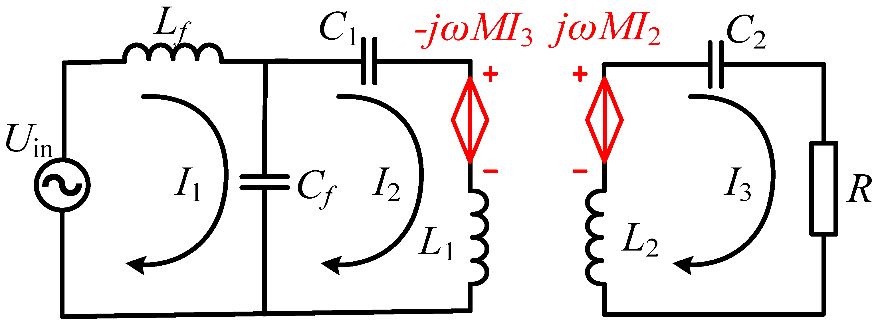
When switch S1 is closed and S2 is open, the system operates in the constant voltage output state. To simplify calculations, a voltage-source equivalent is applied to the coil coupling section; the schematic of the equivalent circuit is shown in Figure 2 where I1, I2, and I3 denote branch current values, ω = 2πf represents the operating angular frequency (f is the operating frequency), and j is the imaginary unit. Owing to the filtering capability of the high-order compensation network, the fundamental harmonic approximation method is adopted for circuit analysis. When the duty cycle of the inverter unit is 50%, the relationship between the DC output UDC and the inverter output Uin is given by
U in = 2 2 π U DC
By integrating the rectifier module and DC load into an equivalent circuit, it can be obtained that
R = 8 π 2 R L
Utilizing the KCL and KVL equations, the circuit relationships can be expressed as
U in = j ω L f I 1 j 1 ω C f ( I 1 I 2 ) j 1 ω C f ( I 1 I 2 ) + j ( ω L 1 1 ω C 1 ) I 2 j ω M I 3 = 0 j ω M I 2 + j ( 1 ω C 2 ω L 2 ) I 3 R I 3 = 0
The resonant relationship of the circuit in CV mode is
ω = 1 L f C f = 1 C 1 ( L 1 L f ) = 1 L 2 C 2
Combining (3) and (4) yields the current values for each branch:
I 1 = M 2 L f 2 R U i n I 2 = 1 j ω L f U i n I 3 = M L f R U i n
The output voltage at the load terminal, UOUT = |I3| × R = MUin/Lf, achieves a load-independent constant voltage output.

2.1.2. CC Output Mode

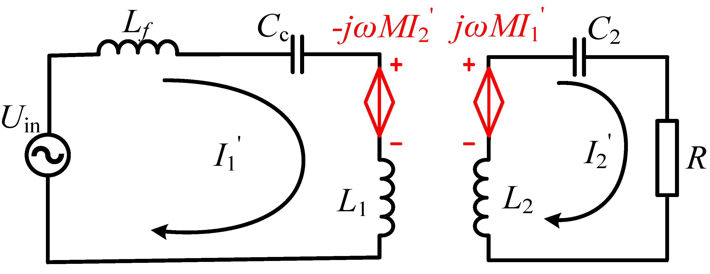
When switch S1 is open and S2 is closed, the system operates in CC output mode. Similarly, the original circuit is equivalent to a voltage source, as shown in Figure 3. Note that for simplicity in subsequent calculations, the parallel capacitors C1 and Ce are equivalent to Cc.
The circuit equations can be listed as follows:
U in = j ( ω L f + ω L 1 1 ω C C ) I 1 j ω M I 2 j ω M I 1 + j ( 1 ω C 2 ω L 2 ) I 2 R I 2 = 0
The resonance relationship of the circuit in CC mode is
ω = 1 ( L f + L 1 ) C C = 1 L 2 C 2
Based on (6) and (7), the branch currents in CC mode can be obtained as follows:
I 1 = R ω 2 M 2 U i n I 2 = j 1 ω M U i n
As shown by I2′, the system now achieves load-independent CC output. Based on the constant operating frequency in CC and CV modes and the resonance relationship, the relationship between Ce and C1 is derived as follows:
C e = ( L 1 L f ) 2 L f C 1

2.2. Analysis of System Efficacy

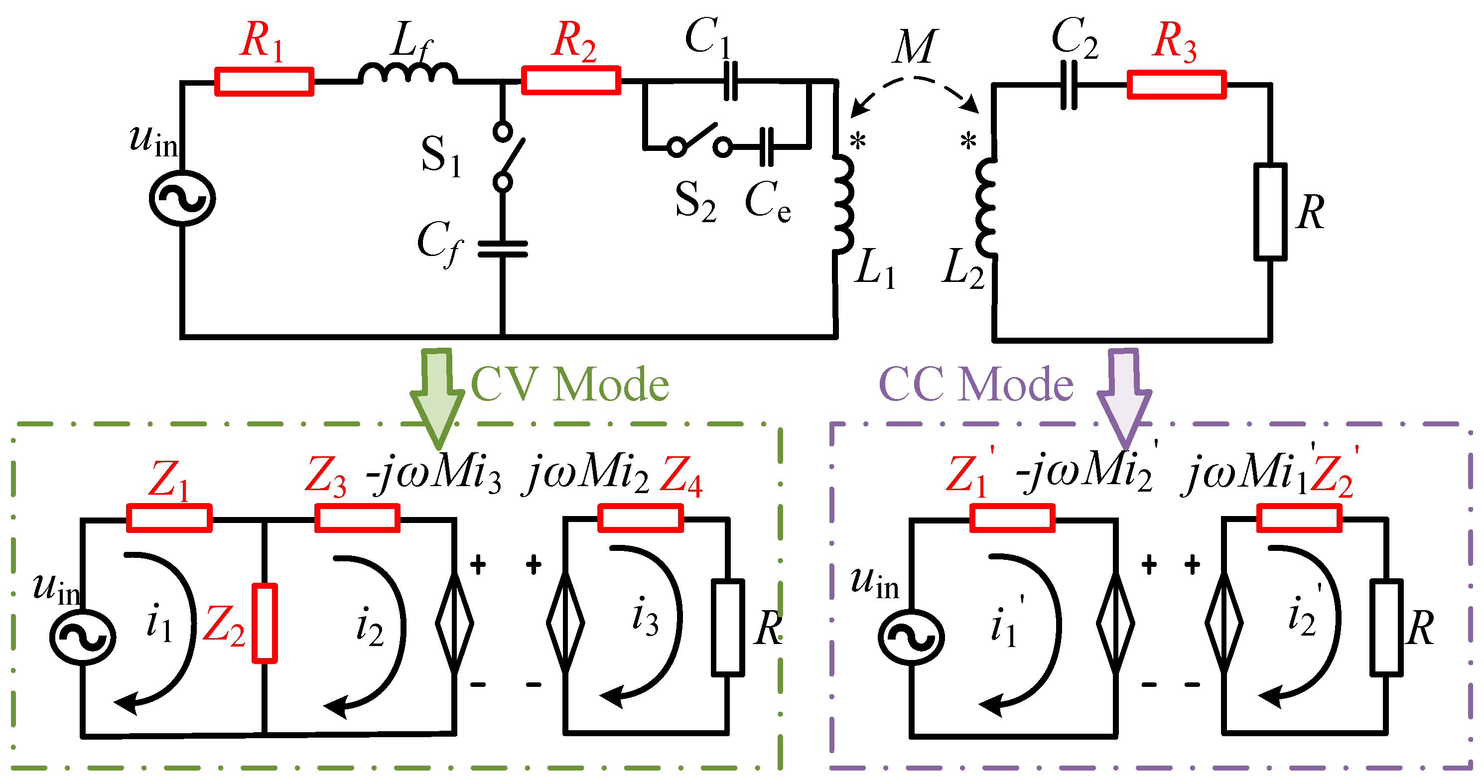
During the verification of the CC/CV output characteristics mentioned above, the parasitic parameters of the compensation components and coil losses are negligible and can be omitted in the theoretical derivation. However, when analyzing the system’s power and efficiency, to better reflect real-world conditions, these factors are incorporated into the analysis. The corresponding circuit and equivalent process are shown in Figure 4.
For computational convenience, the impedance on each branch is represented by Z. For the CV mode, the circuit impedance matrix relationship can be established as
Z 1 + Z 2 Z 2 0 Z 2 Z 2 + Z 3 j ω M 0 j ω M Z 4 + R i 1 i 2 i 3 = u in 0 0
The impedance expression for the current value in each branch can be obtained as follows:
i 1 = M 2 ω 2 + Z 2 + Z 3 R + Z 4 ω 2 M 2 Z 1 + Z 2 + Z 2 Z 3 + Z 1 Z 2 + Z 3 R + Z 4 u i n i 2 = Z 2 R + Z 4 ω 2 M 2 Z 1 + Z 2 + Z 2 Z 3 + Z 1 Z 2 + Z 3 R + Z 4 u i n i 3 = j ω M Z 2 ω 2 M 2 Z 1 + Z 2 + Z 2 Z 3 + Z 1 Z 2 + Z 3 R + Z 4 u i n
Substituting the resonance relationship in CV mode into (11) and simplifying yields
i 1 = R 2 R + R 3 + ω 2 M 2 R 1 R 2 R + R 3 + ω 2 L f 2 R + R 3 + M 2 R 1 u i n i 2 = j ω L f R + R 3 R 1 R 2 R + R 3 + ω 2 L f 2 R + R 3 + M 2 R 1 u i n i 3 = ω 2 M L f R 1 R 2 R + R 3 + ω 2 L f 2 R + R 3 + M 2 R 1 u i n
Furthermore, the input and output power as well as the efficiency of the system under CV mode can be calculated:
P in _ CV = u i n i 1 = ω 2 M 2 R 2 R + R 3 R 1 R 2 R + R 3 + ω 2 L f 2 R + R 3 M 2 R 1 u i n 2 P out _ CV = i 3 2 R = ω 4 M 2 L f 2 R R 1 R 2 R + R 3 + ω 2 L f 2 R + R 3 M 2 R 1 2 u i n 2 η _ CV = ω 4 M 2 L f 2 R R 2 R + R 3 ω 2 M 2 R 1 R 2 R + R 3 + ω 2 L f 2 R + R 3 M 2 R 1
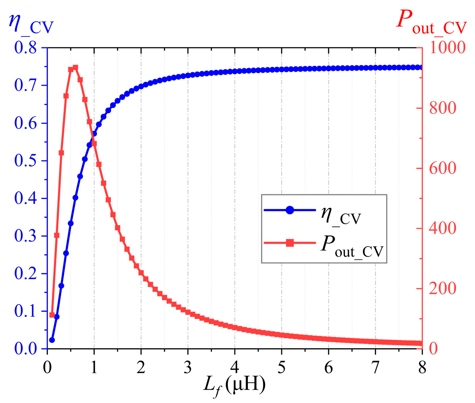
Based on the resonant characteristics of the circuit, once the self-inductances of the coupled coils (L1, L2) and mutual inductance M are known, only the parameter of the compensation inductor Lf in the system requires further determination. For selecting the value of Lf, analysis can be conducted by examining the variation trends of the system output power Pout_CV and efficiency η_CV with Lf, as shown in Figure 5. It can be observed from the figure that when Lf increases within the range of [0.1, 8] μH, Pout_CV and η_CV change significantly, and their curves exhibit opposite monotonic trends after intersecting. On the premise of meeting the power requirements of UAV applications, to maximize the system efficiency, comprehensive analysis leads to the selection of Lf = 2.5 μH. At this value, the system achieves an output power of 170 W with an efficiency of 71.5%.
For CC mode, employing the same analytical method as for CV mode, the circuit impedance matrix relationship can be established:
Z 1 j ω M j ω M Z 2 + R i 1 i 2 = u in 0
Next, the current values in each branch can be calculated as follows:
i 1 = R 3 + R R 1 + R 2 R 3 + R + ω 2 M 2 u i n i 2 = j ω M R 1 + R 2 R 3 + R + ω 2 M 2 u i n
Based on (15), the input and output power as well as the efficiency of the system under CC mode can be further derived as follows:
P in _ CC = R 3 + R R 1 + R 2 R 3 + R + ω 2 M 2 u i n 2 P out _ CC = ω 2 M 2 R R 1 + R 2 R 3 + R + ω 2 M 2 2 u i n 2 η _ CC = ω 2 M 2 R R + R 3 ω 2 M 2 + R 1 + R 2 R 3 + R
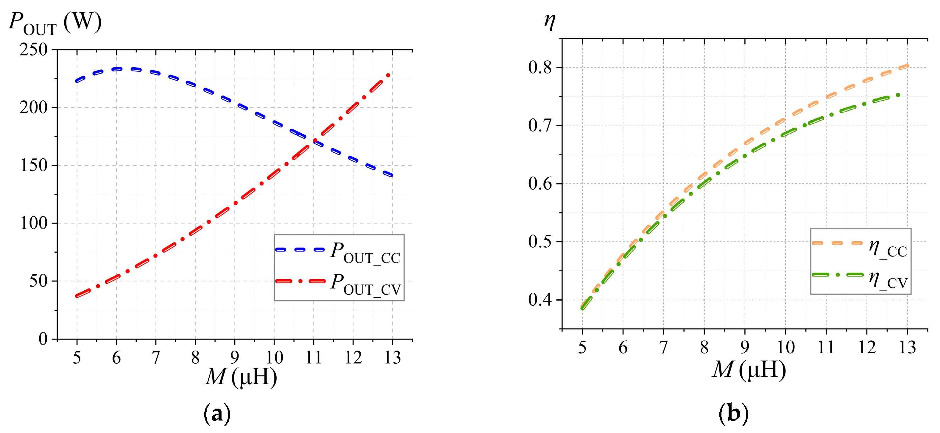
From (16), based on the resonant characteristics of the S-S equivalent circuit, the input power, output power, and efficiency of the system in CC mode depend solely on the equivalent resistances of each branch, the system operating frequency, and M, while being independent of the parameter values of resonant components. Drawing on the comprehensive performance analysis of the system’s CC and CV modes as presented earlier, regardless of the operating mode, M of the coupled coils exerts a significant influence on the system’s output power and efficiency. The variation trends of the system’s output characteristics with M are shown in Figure 6. As observed in Figure 6, in CC mode, the output power Pout_CC first increases and then decreases with rising M; in CV mode, the output power Pout_CV increases monotonically as M increases. For efficiency characteristics, the system efficiencies η_CC and η_CV in both modes increase monotonically with M, and both power and efficiency demonstrate high sensitivity to variations in M.
Thus, to balance the system’s power, efficiency, and stability across both operating modes, designing the magnetic coupling mechanism to achieve reasonable M values and superior anti-misalignment performance is crucial.

3. Design of Anti-Offset Coupling Mechanism

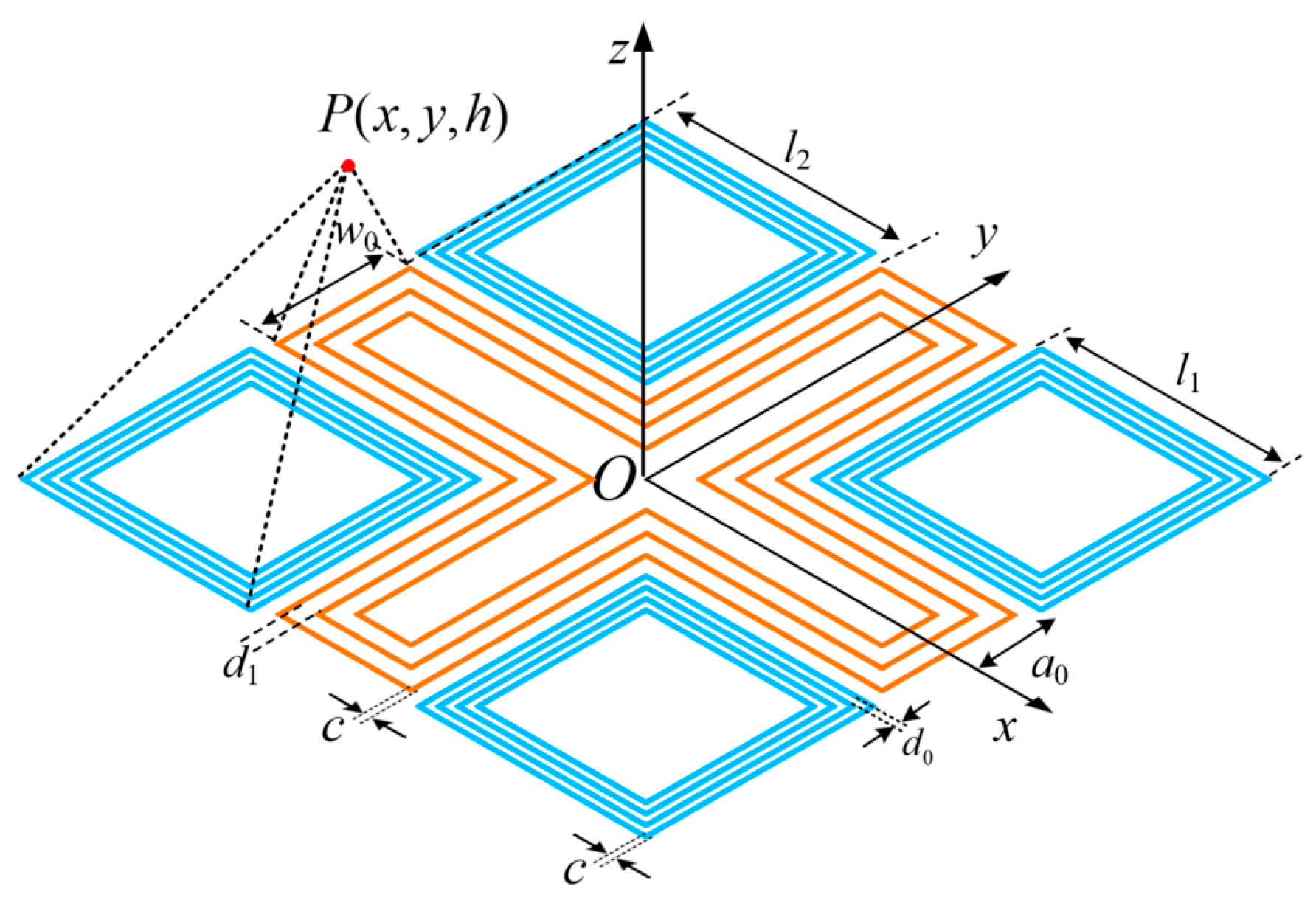
In wireless charging scenarios, UAVs are prone to landing misalignment due to complex outdoor environments. This induces abrupt variations in mutual inductance M, subsequently causing the system to deviate from a stable CC/CV output state. Thus, the core objective of designing an anti-misalignment coupling mechanism is to enhance axial magnetic field uniformity in the charging region, suppress magnetic flux leakage, and sustain the stability of M under misalignment conditions. In this section, a 2 × 2 square coil array serves as the basic structure, and a “+” shaped compensation coil is introduced to mitigate the magnetic field defects of the basic array, thereby forming a coupling mechanism with superior anti-misalignment performance, as shown in Figure 7.
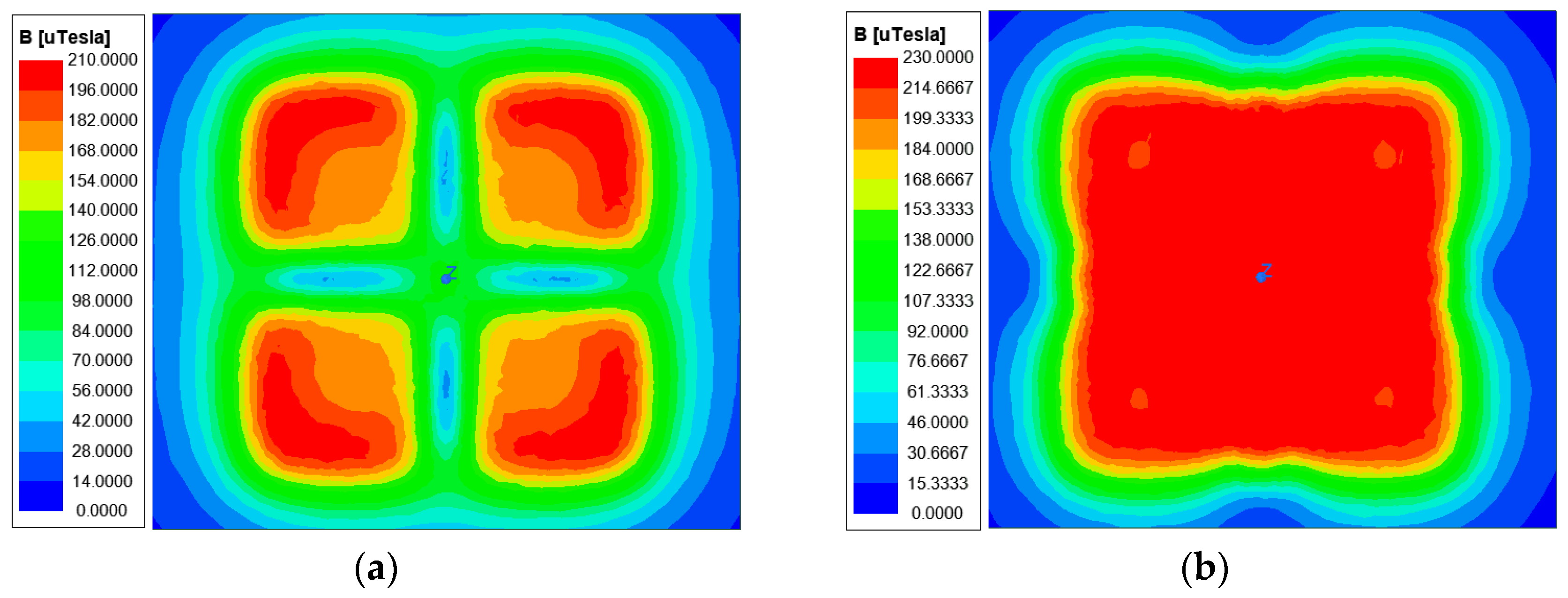
Specifically, this structure consists of four square transmitter coil units with identical geometric parameters and a central “+” shaped coil, all wound in series. The current direction and magnitude are kept consistent to achieve the superposition effect of the axial magnetic field, and the geometric parameters of the transmitting mechanism are listed in Table 1. The structural parameters of the square coils are designed based on the UAV landing gear spacing and length. The edge spacing between adjacent coils is 2a0 = 40 mm, which prevents excessive magnetic field superposition between adjacent coils from causing local magnetic saturation while reserving space for the subsequent installation of the “+”-shaped compensation coil. Ansys Maxwell 2021 R1 is utilized to conduct magnetic field simulation on the basic 2 × 2 square coil array, and the magnetic field contour map is shown in Figure 8a. It can be observed that the magnetic field intensity along the x-axis and y-axis of the array is significantly lower than that in the surrounding areas, forming a “+”-shaped low-intensity region. Thus, while the basic 2 × 2 square coil array can expand the UAV wireless charging area, it fails to meet the requirement for anti-misalignment performance.
To address the aforementioned magnetic field low-intensity regions, a custom-designed “+”-shaped compensation structure is developed based on the magnetic field distribution of the square array coils, aiming to improve the magnetic field uniformity at the transmitter through magnetic field superposition. By optimizing the number of turns, long-side length l2, and short-side width w0 of the “+” shaped compensation coil, the final structural parameters are listed in Table 1. To verify the effectiveness of the compensation structure, magnetic field simulation analysis is performed on the transmitter with the “+” shaped compensation coil introduced, and the results are shown in Figure 8b. A comparison with Figure 8a reveals that the uniformity of the magnetic field at the transmitter is significantly improved after introducing the compensation coil; meanwhile, the average magnetic field intensity in the target operating region is enhanced; additionally, magnetic flux leakage around the transmitting mechanism is effectively suppressed. These results validate the feasibility and superiority of the “+”-shaped compensation structure.
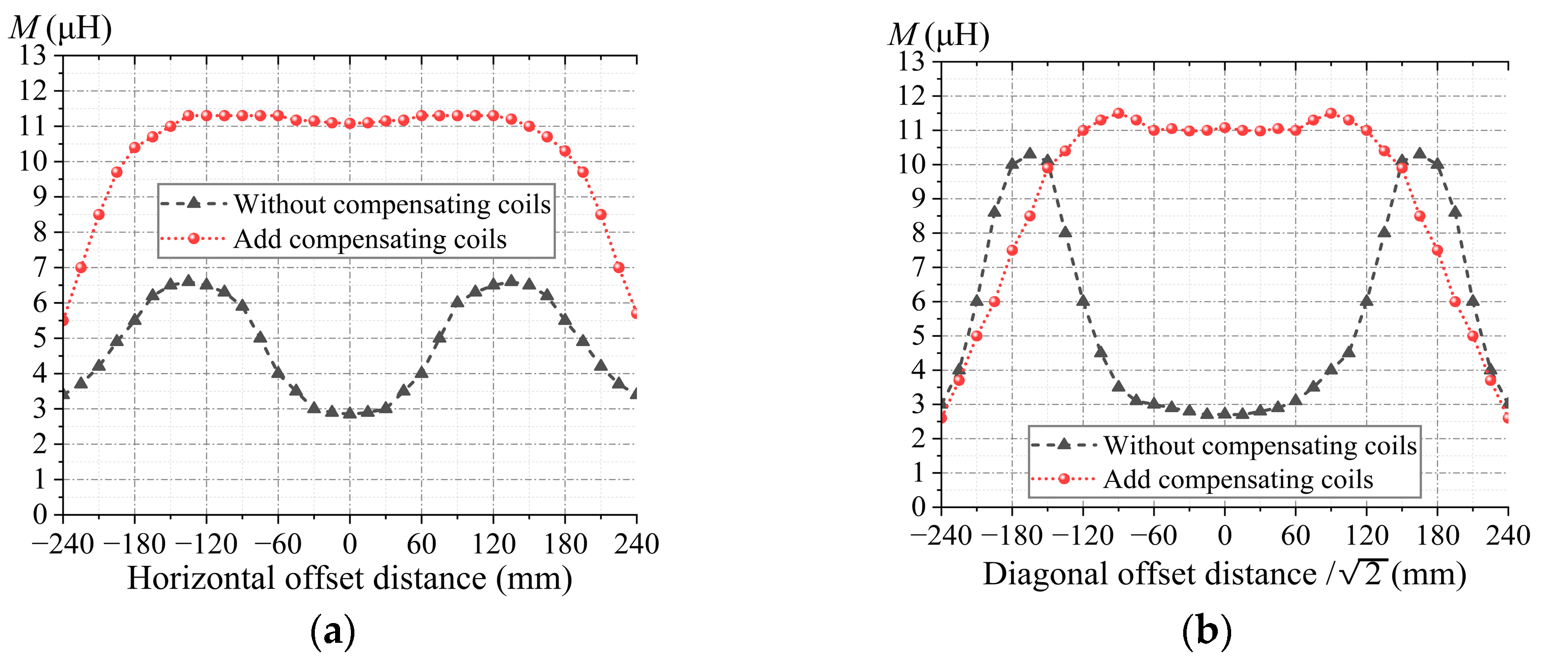
For the receiver design, considering the limited payload space of UAVs and lightweight design requirements, a square coil is selected. The parameters of the coil are 250 mm × 250 mm in side length, ten turns. It is mounted between the two landing gears of the UAV to ensure initial alignment accuracy with the transmitter. To evaluate the anti-misalignment capability of the coupling mechanism, simulation analysis is conducted on the mutual inductance M. Given the axisymmetric characteristics of the coupling structure, the simulation is simplified by analyzing only two types of horizontal misalignment conditions: (1) misalignment along the x-axis, with the offset range set to [−240, 240] mm; and (2) misalignment along the x-y diagonal direction, with the offset range set to [−240√2, 240√2] mm. To further verify the impact of the compensation coil on the anti-misalignment performance of the coupling system, a comparison is made between the mutual inductance characteristics of systems without compensation coil and with compensation coil during the simulation, and the results are shown in Figure 9.
As observed from the figure, when no compensation coil is used, the mutual inductance M fluctuates significantly with the offset distance, indicating poor anti-misalignment capability of the coupling mechanism. In contrast, after adding the “+”-shaped compensation coil, M exhibits small fluctuations within the horizontal offset range [−150, 150] mm and diagonal offset range [−150√2, 150√2] mm; moreover, the magnitude of M is nearly twice that of the system without the compensation coil. These results demonstrate that the introduction of the compensation coil significantly enhances the system’s anti-misalignment and power transfer capability.

4. Experimental Verification

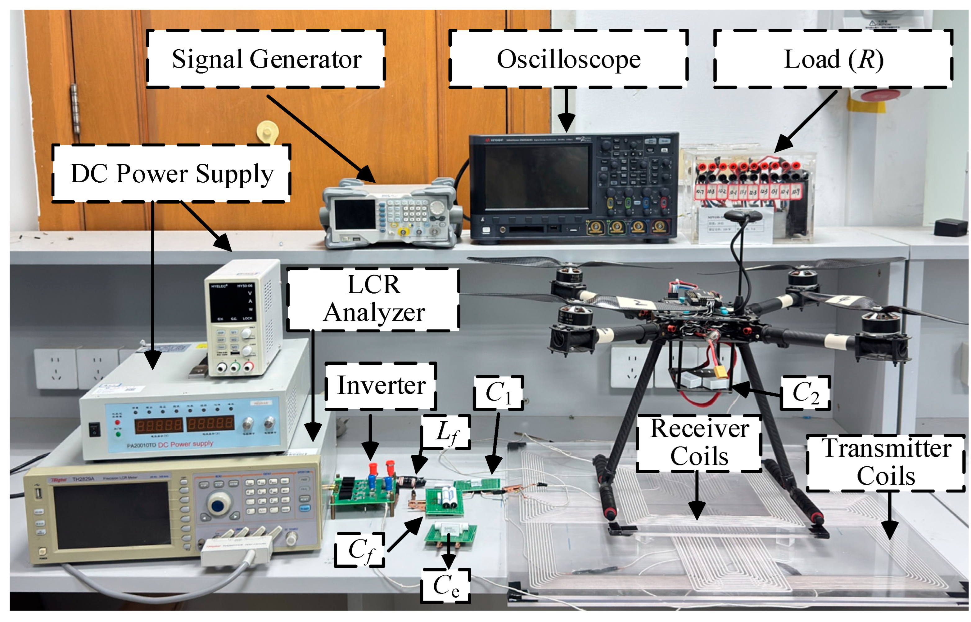
To verify the performance of the proposed topology-switching-based UAV CC/CV WPT system, an experimental platform is built, as shown in Figure 10. The experimental design matches the system’s theoretical parameters and the structure of the coupling mechanism; in accordance with the Qi standard, the system’s operating frequency is set to 85 kHz, and the measured relevant electrical parameters of the system are listed in Table 2. This experiment primarily verifies two core performances of the system mentioned earlier: CC/CV output stability and anti-misalignment capability.

4.1. Verification of System CC/CV Capability

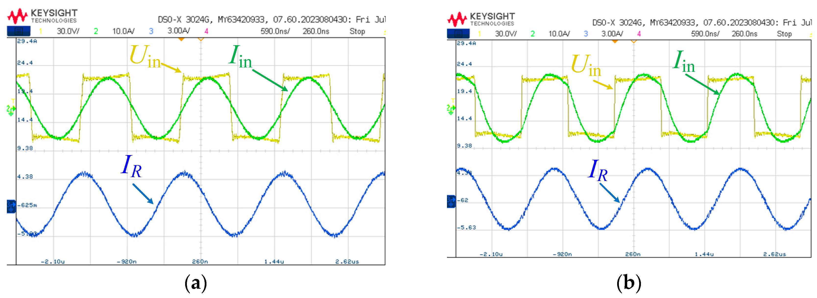
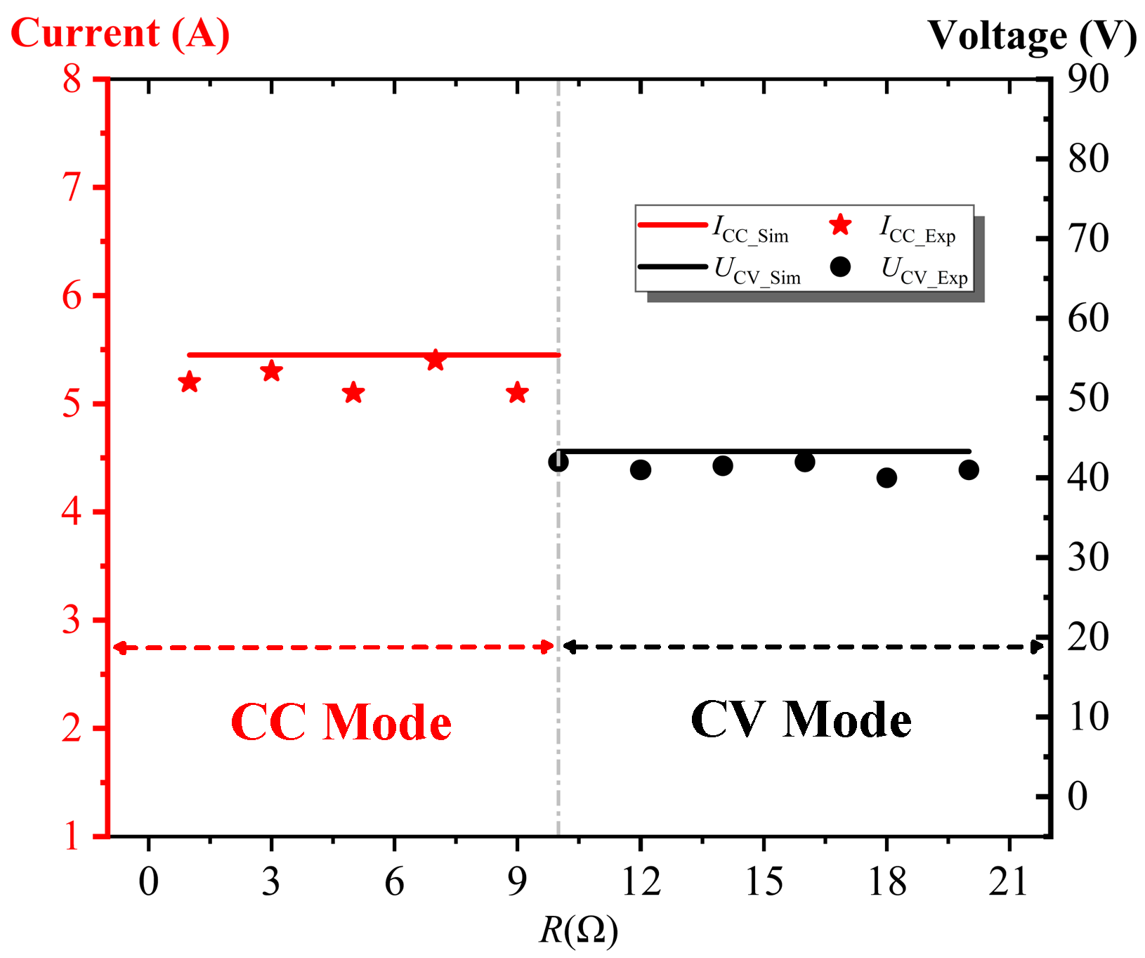
Given that the equivalent resistance of the UAV battery increases monotonically with charging time during the charging process, the switching point between CC and CV modes is set to R = 10 Ω. The final resonant frequency of the system is 85.106 kHz, and the input and output waveforms under CC/CV modes are shown in Figure 11.
To verify the CC/CV output characteristics of the system, the variation range of R is set to [1, 20] Ω with an incremental step size of 2 Ω, and the experimental results are shown in Figure 12. It can be observed from the figure that the system achieves relatively stable load-independent characteristics, and the experimental results are in good agreement with the calculated results.

4.2. Verification of System Anti-Offset Capability

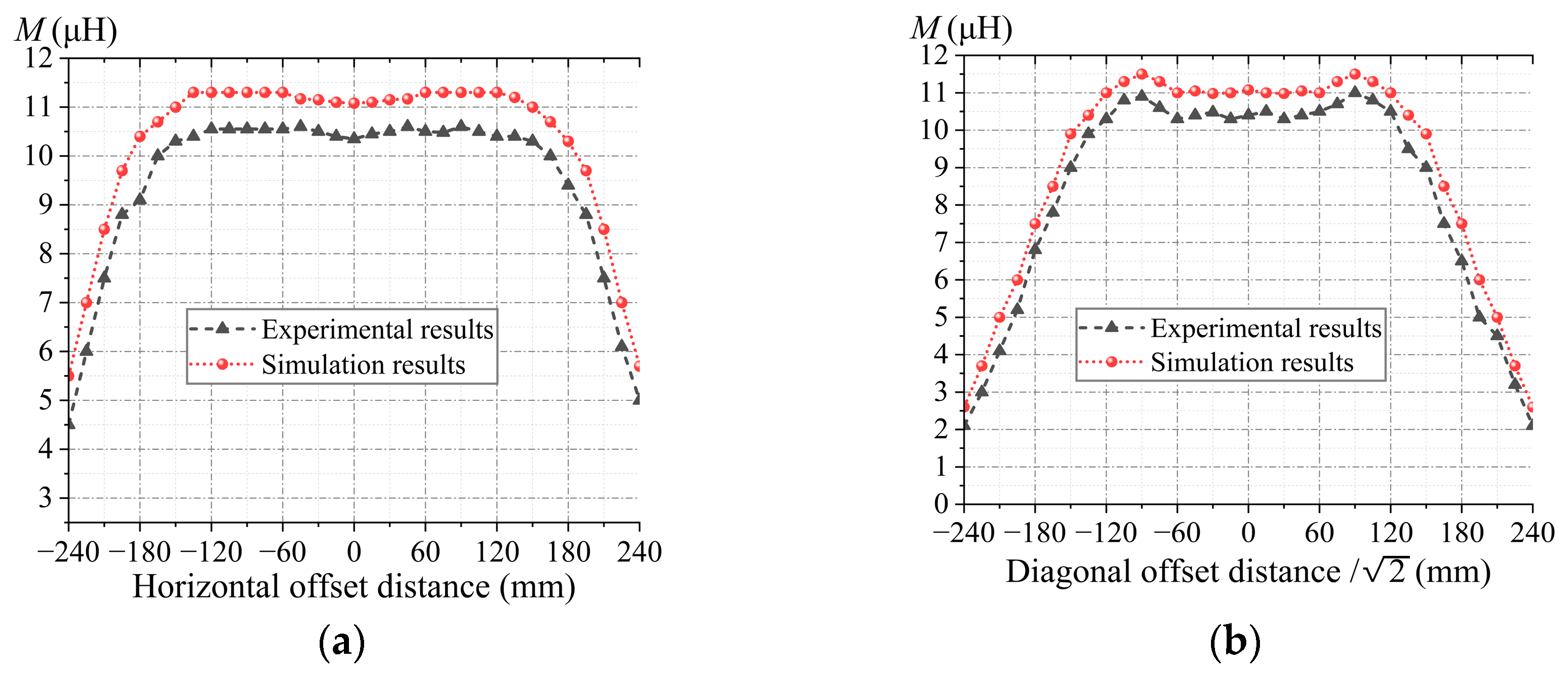
To verify the anti-misalignment capability of the coupling mechanism designed earlier, an impedance analyzer is used to measure the variation in mutual inductance M when the receiver is moved, within the same offset range. Results are shown in Figure 13. As observed from the figures, within the horizontal offset range [−150, 150] mm and diagonal offset range [−90√2, 90√2] mm, the proposed coupling mechanism exhibits minimal fluctuations in mutual inductance while maintaining a value above 10 μH, demonstrating excellent anti-misalignment capability and power transfer capability. Furthermore, theoretical formulas and simulated data are in good agreement with the experimental results, further validating the rationality of the coil design described earlier.
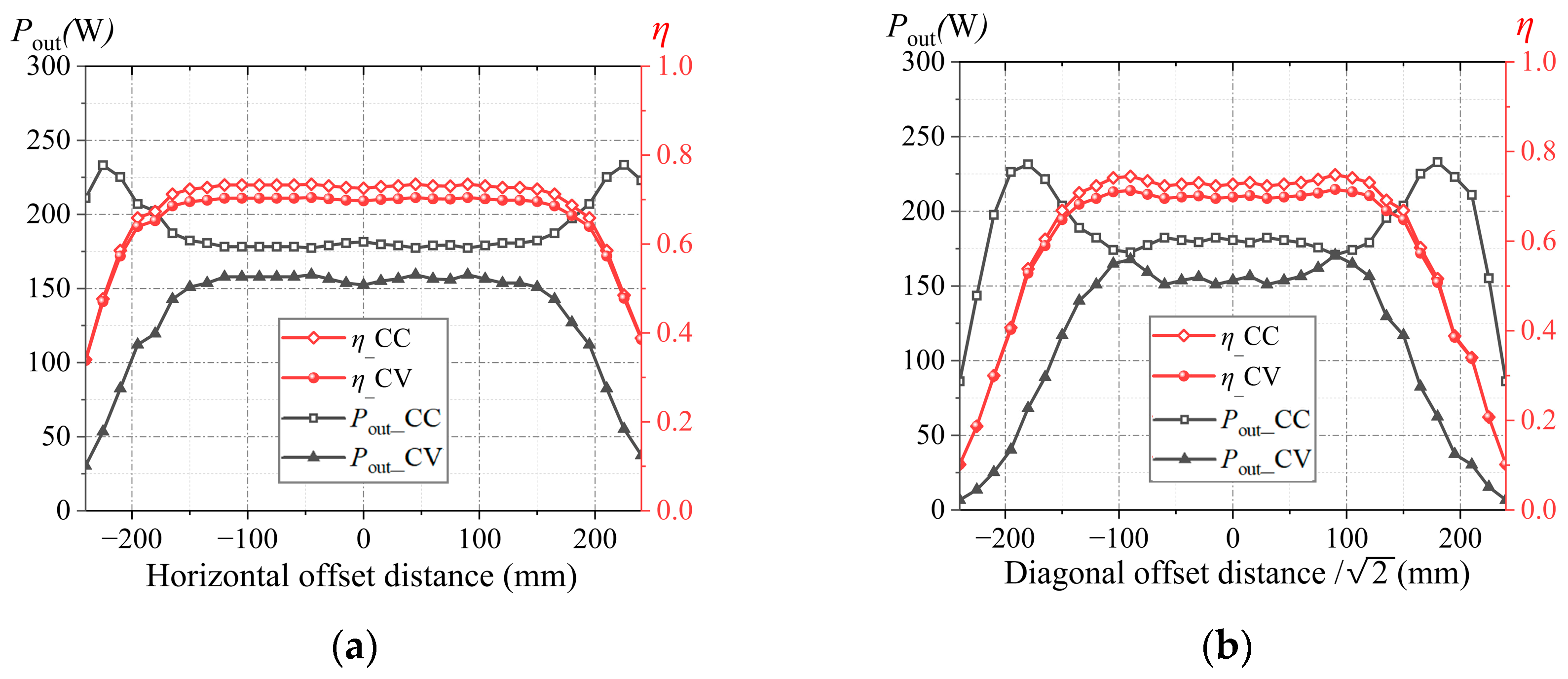
Further, to test the sensitivity of the proposed UAV wireless charging system to variations in mutual inductance, system power and efficiency tests were conducted within the same offset range; the test results are shown in Figure 14. As can be observed, in the aligned state, when the system operates in CC mode, the output power reaches 180.6 W with a transmission efficiency of 72.73%; when operating in CV mode, the output power is 153.7 W with a transmission efficiency of 69.87%. Within the high anti-misalignment region, the system stably maintains an output power above 150 W and a transmission efficiency above 70%, with its fluctuation amplitude gentler than that of mutual inductance in Figure 13.
This result indicates that the parameters of the compensation components designed under the LCLC-CL topology further enhance the tolerance of the charging platform to UAV positional misalignment. Additionally, the differences in power and efficiency between CC and CV modes are small, which means the system does not cause shocks to system components or the load before and after CC/CV mode switching, and can sustain a stable charging state continuously.

5. Discussion

UAVs suffer critical autonomous charging bottlenecks with traditional WPT systems, such as limited endurance, unstable CC/CV switching, heavy payload, and poor anti-misalignment. This article addresses these via a topology-switching-based CC/CV WPT system: the lightweight LCC-S topology realized load-independent CC/CV switching without extra receiver circuits; the 2 × 2 coil array with a central “+” shaped coil maintained mutual inductance > 10 μH, power > 150 W, and efficiency > 70% under large offsets; the impedance matrix model optimized Lf = 2.5 μH to achieve 170 W output and 71.5% efficiency. This integrated solution uses off-the-shelf components, ensuring good scalability. It resolves the system-level flaws of previous single-aspect studies. Meanwhile, it directly enables reliable autonomous UAV charging. This is an essential breakthrough—it helps extend the endurance of inspection and logistics UAVs, and promotes their large-scale practical application. The system has two main limitations. One is the 170 W power scalability—it is insufficient for large UAVs. The other is that it only supports single-UAV charging. Future research will focus on two directions. First is high-power adaptation, which will adopt modular topology and wide-bandgap devices. Second is multi-UAV simultaneous charging, which will use adaptive power allocation, magnetic shielding, and scheduling algorithms. In addition, hybrid solar integration has potential—it can further boost UAV endurance.

Author Contributions

Conceptualization, J.C., W.C. and H.W.; methodology, H.W., C.R. and C.X.; software, J.C. and H.W.; validation, Y.G. and J.W.; formal analysis, J.C., C.R. and C.X.; investigation, W.C. and H.W.; resources, C.R. and C.X.; data curation, Y.G. and J.W.; writing—original draft preparation, J.C., W.C. and H.W.; writing—review and editing, J.C., W.C. and H.W.; visualization, J.C. and H.W.; supervision, C.R. and C.X.; project administration, C.R. and C.X.; funding acquisition, C.R. and C.X. All authors have read and agreed to the published version of the manuscript.

Funding

This research received no external funding.

Institutional Review Board Statement

Not applicable.

Informed Consent Statement

Not applicable.

Data Availability Statement

The original contributions presented in the study are included in the article, further inquiries can be directed to the corresponding author.

Conflicts of Interest

The authors declare no conflict of interest.

Abbreviations

The following abbreviations are used in this manuscript:
UAVsUnmanned aerial vehicles
WPTWireless power transfer
CCConstant current
CVConstant voltage
DCDirect current
ACAlternating current

References

  1. Lv, X.; Dai, X.; Yu, F.; Li, X.; Wang, H.; Sun, Y.; Hu, J. A High Misalignment Tolerance SCC-WPT System with Relay Single Capacitive Coupler for UAV Wireless Charging Applications. IEEE Trans. Power Electron. 2025, 40, 10372–10377. [Google Scholar] [CrossRef]
  2. Rong, C.; Guo, Y.; Xu, Y.; Wang, H.; Zhang, X.; Han, W.; Xia, C.; He, X. Cavity Resonator-Based WPT System Utilizing Rotating Magnetic Field for Omnidirectional Charging. IEEE J. Emerg. Sel. Top. Power Electron. 2025, 13, 3955–3965. [Google Scholar] [CrossRef]
  3. Guo, W.; Xu, M.; Tao, Y.; Liu, W.; Zhou, H.; Guan, X.; Yang, R.; Ge, Z.; Xue, R.; Zhang, Z.; et al. Integrated horizontal convective PCR system for clinical diagnostics. Sci. Adv. 2025, 11, eadx8434. [Google Scholar] [CrossRef] [PubMed]
  4. Yang, L.; Chen, X.; Xing, D.; Li, J.; Tian, L.; Bu, Z.; Sun, J.; Wen, H.; Zhao, Y.; Yang, T.; et al. Design and Verification of Adaptive CC/CV Mode Switching Wireless Power Transfer System for UAVs Based on High Switching Frequency Single Switch LC Inverter. IEEE J. Emerg. Sel. Top. Power Electron. 2024, 12, 5990–6006. [Google Scholar] [CrossRef]
  5. Dou, R.T.; Zhang, X.; Li, Y.J.; Zhang, P.C.; Yang, Q.X. Review on Application Development and Research of Electromagnetic Shielding in Magnetically Coupled Resonant Wireless Power Transfer Systems. Proc. CSEE 2023, 43, 6020–6040. [Google Scholar]
  6. Rong, C.; Wang, H.; Gao, H.; Cai, W.; Han, W.; Zhang, X.; Jie, H.; Aime, L.-E.; Xu, Y.; Zhao, Z. Magnetically Coupled Resonant Wireless Power Transfer for Internet of Things Perception Layer: A Review. Renew. Sustain. Energy Rev. 2025, 223, 116013. [Google Scholar] [CrossRef]
  7. Yang, B.; Lu, Y.; Peng, Y.; He, S.; Chen, Y.; He, Z.; Mai, R.; Wang, Z. Analysis and Design of a T/S Compensated IPT System for AGV Maintaining Stable Output Current Versus Air Gap and Load Variations. IEEE Trans. Power Electron. 2021, 37, 6217–6228. [Google Scholar] [CrossRef]
  8. Gupta, R.; Samanta, S. A Novel Parameter Tuning for LCL–LCL WPT with Combined CC/CV Charging and Improved Harmonic Performance. IEEE Trans. Ind. Electron. 2024, 71, 13969–13979. [Google Scholar] [CrossRef]
  9. Li, Z.Q.; Zhang, C.X.; Wang, J.B.; Wang, Z.M.; Huang, S.D. Study on Constant Current and Constant Voltage of Wireless Power Transfer System Based on Frequency Conversion Reconstructed S/SP Topology. Trans. China Electrotech. Soc. 2024, 39, 4718–4732. [Google Scholar]
  10. Liu, Y.; Feng, H. Maximum Efficiency Tracking Control Method for WPT System Based on Dynamic Coupling Coefficient Identification and Impedance Matching Network. IEEE J. Emerg. Sel. Top. Power Electron. 2020, 8, 3633–3643. [Google Scholar] [CrossRef]
  11. Zhang, K.; Ye, T.; Yan, Z.; Song, B.; Hu, A.P. Obtaining Maximum Efficiency of Inductive Power-Transfer System by Impedance Matching Based on Boost Converter. IEEE Trans. Transp. Electrific. 2020, 6, 488–496. [Google Scholar] [CrossRef]
  12. Wang, X.; Xu, J.; Lu, S.; Ren, S.; Leng, M.; Ma, H. Single-Receiver Multioutput Inductive Power Transfer System with Independent Regulation and Unity Power Factor. IEEE Trans. Power Electron. 2022, 37, 1159–1171. [Google Scholar] [CrossRef]
  13. Zhang, S.T.; Zhao, J.B.; Wu, Y.B.; Mao, L.; Liang, C. Study on Soft Switching Technology of Class E Inverter for Wireless Power Transfer Based on Self-Mutual Inductance Regulation. Trans. China Electrotech. Soc. 2021, 36, 4558–4566. [Google Scholar]
  14. Villa, J.L.; Sallan, J.; Osorio, J.F.S.; Llombart, A. High-Misalignment Tolerant Compensation Topology for ICPT Systems. IEEE Trans. Ind. Electron. 2012, 59, 945–951. [Google Scholar] [CrossRef]
  15. Yang, Y.; Cao, G.M.; Li, H.X. Positioning and Direction Guidance Method of Wireless Charging System Based on 3U-Type Auxiliary Coil. Chin. J. Sens. Actuators 2023, 36, 1835–1844. [Google Scholar]
  16. Deng, Q.J.; Liu, J.T.; Chen, C.; Zhou, H.; Hu, W.S. Development of Three-Phase Phase-Shifted Controlled Inverter for Wireless Power Transfer System. Trans. China Electrotech. Soc. 2017, 32, 52–61. [Google Scholar]
  17. Wang, J.; Huang, Z. A Single-Switch WPT Circuit with Inherent CCO–CVO for Battery Charging. IEEE Trans. Transp. Electrific. 2023, 10, 1957–1968. [Google Scholar] [CrossRef]
  18. Rong, C.; Chen, M.; Duan, X.; Liu, Y.; Wu, J.; Zeng, Y.; He, X.; Liao, Z.; Xia, C. Optimized Design of Passive Array Coils for High-Efficiency and Anti-Misalignment WPT System. IEEE Trans. Power Electron. 2024, 39, 6504–6514. [Google Scholar] [CrossRef]
  19. Tao, Y.; Gao, Y.; Liu, Z.; Chen, Y.; Liu, W.; Yu, G.; Ren, Y. Many-body electrohydrodynamic contact dynamics in alternating-current dielectrophoresis: Resolving hierarchical assembly of soft binary colloids. Phys. Fluids 2025, 37, 082043. [Google Scholar] [CrossRef]
  20. Zaheer, A.; Covic, G.A.; Kacprzak, D. A Bipolar Pad in a 10-kHz 300-W Distributed IPT System for AGV Applications. IEEE Trans. Ind. Electron. 2014, 61, 3288–3301. [Google Scholar] [CrossRef]
  21. Wang, Y.J.; Lu, K.X.; Yao, Y.S.; Liu, X.S.; Xv, D.G. Wireless Power Transfer System for Electric Vehicles with Strong Misalignment Resistance Performance. Proc. CSEE 2019, 39, 3907–3917. [Google Scholar]
  22. Xiao, H.H.; Zhou, Q.S.; Xiong, S.X.; Yang, Y.; Xie, S.Y. Wireless Power Transfer System Resisting Misalignment and Deflection Based on Double-Layer Orthogonal DD Coils. Trans. China Electrotech. Soc. 2022, 37, 4004–4018. [Google Scholar]
  23. Peng, Y.E.; Zhang, B.S.; Yang, B.; He, S.J.; Chen, Y.; Mai, R.K. High Misalignment-Resistant IPT System Based on Double Helix Orthogonal Coils. Proc. CSEE 2022, 42, 7352–7363. [Google Scholar]
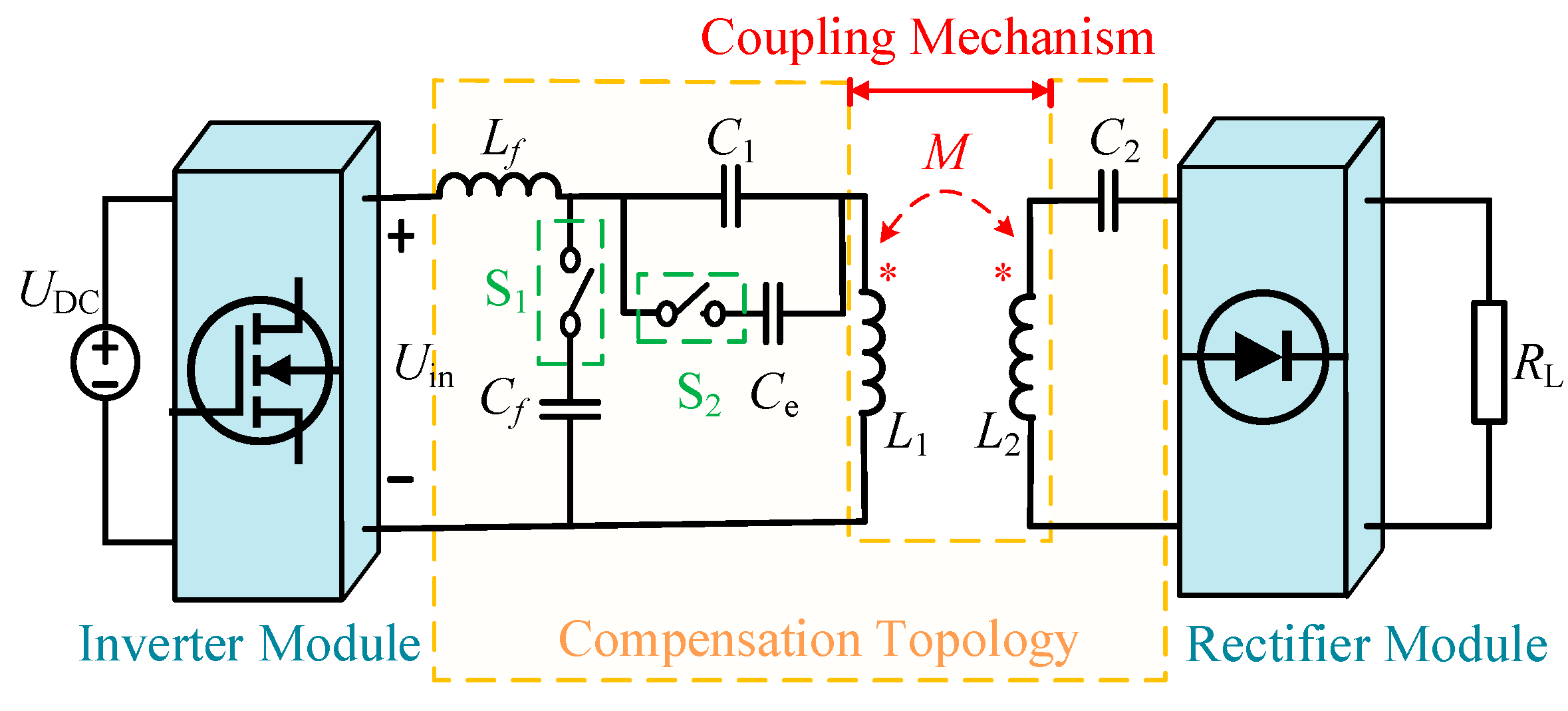
Figure 1. Schematic diagram of the system’s circuit.
Applsci 15 11932 g001
Figure 2. Schematic diagram of equivalent circuit in CV mode.
Applsci 15 11932 g002
Figure 3. Schematic diagram of the equivalent circuit in CC mode.
Applsci 15 11932 g003
Figure 4. Circuit equivalent diagram under fault conditions.
Applsci 15 11932 g004
Figure 5. System power and efficiency trends with Lf in CV mode.
Applsci 15 11932 g005
Figure 6. System power and efficiency trends with M: (a) system output power varies with M; (b) system efficiency varies with M.
Applsci 15 11932 g006
Figure 7. Transmitter coil structure incorporating a “+” shaped compensation.
Applsci 15 11932 g007
Figure 8. Magnetic field distribution of transmitter coils before and after introducing the “+”-shaped compensation, (a) traditional 2 × 2 array coil; (b) after introducing the “+”-shaped coil.
Applsci 15 11932 g008
Figure 9. Simulation of anti-offset performance of coupling mechanisms, (a) variation in M when offset along the x-axis; (b) variation in M when offset along the diagonal of the x-y plane.
Applsci 15 11932 g009
Figure 10. Schematic diagram of the experimental setup.
Applsci 15 11932 g010
Figure 11. Voltage and current waveform of experiment in CC/CV mode; (a) CC mode; (b) CV mode.
Applsci 15 11932 g011
Figure 12. Verification of system CC and CV performance.
Applsci 15 11932 g012
Figure 13. Variation in mutual inductance under offset in experiments: (a) variation in M when offset along the x-axis; (b) variation in M when offset along the diagonal of the x-y plane.
Applsci 15 11932 g013
Figure 14. Variation in output power and efficiency under offset in experiments: (a) variation when offset along the x-axis; (b) variation when offset along the diagonal of the x-y plane.
Applsci 15 11932 g014
Table 1. Structural Parameters of the Transmitter.
ParameterValue
Side length of the square coils l1250 mm
Distance between the square coils and the coordinate axes a020 mm
Interturn spacing of the square coil d01 mm
Turns of the square coil10
Wire diameter c2 mm
Width of the compensation coil w0124 mm
Length of the compensation coil l2220 mm
Interturn spacing of the compensation coil d12 mm
Turns of the compensation coil12
Transmission distance5 mm
Table 2. Electrical Parameters Measured in The Experiment.
ParameterValue
Self-inductance of transmitter coils L1176.03 μH
Parasitic resistance of transmitter coils R21.061 Ω
Self-inductance of receiver coils L242.07 μH
Parasitic resistance of receiver coils R30.144 Ω
Compensation inductor Lf2.54 μH
Compensation capacitor C11.38 μF
Compensation capacitor Ce20.18 nF
Compensation capacitor C283.36 nF
Parasitic resistance of Lf R10.02 Ω
Disclaimer/Publisher’s Note: The statements, opinions and data contained in all publications are solely those of the individual author(s) and contributor(s) and not of MDPI and/or the editor(s). MDPI and/or the editor(s) disclaim responsibility for any injury to people or property resulting from any ideas, methods, instructions or products referred to in the content.