Abstract
To investigate the seepage and deformation failure characteristics of deep unloaded rock mass under cyclic loading and unloading disturbance, a series of triaxial cyclic loading and unloading tests were conducted on granite. These tests were performed under varying seepage pressures and unloading conditions to analyze the mechanical properties, seepage behavior, and fracture failure characteristics of the material. The findings indicate the following: (1) An increase in seepage pressure and unloading magnitude results in pronounced radial expansion characteristics in the rock specimens following cyclic loading and unloading. Additionally, the axial, radial, and volumetric residual strains exhibit a nonlinear acceleration in growth as the number of cyclic loading and unloading applications increases. (2) The elastic modulus of rocks exhibits two distinct phases: an initial rapid decline followed by a steady-state decrease. Concurrently, Poisson’s ratio demonstrates an initial decrease, which is subsequently followed by a consistent increase. Furthermore, when considering the effects of unloading, the inflection point of the Poisson’s ratio curve will occur earlier. (3) The interplay between seepage pressure and unloading conditions markedly exacerbates the damage and degradation of the rock. Specifically, under conditions of 70% unloading and a seepage pressure of 4 MPa, the peak stress of the rock specimen is reduced by 21.90%, and the peak intensity permeability increases by 446.70%. (4) Under conditions of high confining pressure and elevated seepage pressure, V-shaped conjugate shear fracture surfaces are likely to develop during the cyclic loading failure of granite, accompanied by a limited number of secondary shear cracks. Concurrently, tensile failure surfaces that are parallel to the maximum principal stress are also observed under the influence of unloading.
1. Introduction
As the economy progresses and shallow resources become increasingly depleted, extensive geotechnical projects in sectors such as Water conservancy and hydropower, Transportation, and energy extraction are progressively penetrating deeper into the Earth’s crust [1]. This advancement inevitably leads to encounters with intricate underground stress environments, often described by the phenomenon of “Elevated ground stress, increased ground temperature, significant seepage pressure, and pronounced unloading disturbances”. For example, in the context of the sectional excavation of deeply buried water tunnels and dam foundations [2,3,4], periodic water level regulation within the reservoir [5] or seismic activity [6] can frequently induce a stress state in the surrounding rock mass of the tunnel or the rock mass of the dam foundation that is affected by cyclic loading. The mechanical properties and deformation failure characteristics of rock masses subjected to cyclic loading exhibit notable differences compared to those observed under conventional stress conditions [7,8]. Furthermore, the effects of high seepage pressure exacerbate the deterioration characteristics of the unloaded rock masses [9]. The seepage characteristics of rock mass are also subject to continual alteration due to cyclic loading, influencing factors such as groundwater seepage path and rate. Additionally, upon reaching the deeper strata, the nonlinear deformation that occurs prior to the failure of the rock mass will become increasingly pronounced. Additionally, the occurrence of high-magnitude disasters resulting from various engineering activities will be more substantial [10]. Consequently, a thorough examination of the mechanical, seepage, and fracture characteristics of deep unloaded rock mass subjected to cyclic loading holds substantial practical significance and engineering value.
In recent years, a significant number of researchers have engaged in comprehensive investigations of rock subjected to cyclic loads from various aspects. In the context of cyclic loading and unloading, the strength and deformation characteristics are intricately linked to the confining pressure [11,12]. As the confining pressure rises, both the elastic modulus and Poisson’s ratio of the rock specimen exhibit a general increase [13]. Furthermore, an increase in water content markedly improves the plastic deformation capacity and degradation effect of the rock specimen [14,15]. The loading elastic modulus of the rock exhibits an increase corresponding to the number of cycles applied [16]. Furthermore, the dynamic elastic modulus of red sandstone and granite exhibits an increase in response to elevated strain ratios and stress ratios [17]. In the investigation of the loading and unloading amplitude within the cyclic process, it was observed that the strain exhibited by the rock demonstrated a nonlinear escalation in response to the variations in loading and unloading amplitude [18]. Elevated upper limit values of the loading cycle, coupled with insufficient unloading, are likely to expedite the progression of irreversible crack damage and the swift propagation of cracks [19]. In the course of performing cyclic loading and unloading experiments on rock specimens exhibiting joints, it was observed that the dynamic strength of the rock diminishes as the joint dip angle increases [20]. Meanwhile, Xu et al. [21,22,23,24,25] analyzed the influence of joint fractures on rock damage characteristics. The analysis of rock deformation reveals that the irreversible axial plastic deformation of the rock will lead to an increase in its elastic stiffness, while the volume strain related to fracture initially rises and then decreases [26]. Studies on the macroscopic fracture morphology of rocks have shown that sandstone predominantly exhibits failure through shear mechanisms when subjected to different confining pressures [27]. The failure mechanisms observed in phyllite specimens subjected to cyclic loading predominantly encompass tensile-shear failure, shear-slip failure, and splitting-shear failure [28]. Additionally, the findings from the energy analysis indicate that the failure of rock is related to energy dissipation [29,30]. A distinct linear correlation exists between the reduction in rock wave velocity and the dissipated energy [31]. Throughout the discontinuous multi-level fatigue loading process, there is an increase in both elastic energy and dissipated energy in granite as the stress level escalates [32]. Additionally, Wang et al. [33,34] analyzed the damage characteristics of marble subjected to the simultaneous effects of freeze–thaw cycles and cyclic loads, as well as the progression of crack formation.
Additionally, there has been a continuous emergence of research focused on the damage and deformation properties of rocks subjected to cyclic loading within seepage pressure conditions. Research has demonstrated that both the number of loading cycles and pore water pressure exert a considerable influence on the damage and failure properties of rocks [35,36]. There is a correlation between the damage state of the rock and variations in permeability, with permeability being significantly associated with the proliferation of micro-cracks throughout the damage process [37]. Consequently, the failure modes associated with cyclic loading tests that involve pore pressure are notably more complex [38]. Meanwhile, the presence of water pressure significantly reduces the bearing capacity and energy storage capacity of rocks under cyclic loading and unloading conditions [39,40]. Regarding the deformation of rocks, when the seepage pressure of the specimen is comparatively low, specifically at levels such as 1.5 megapascals and 2 megapascals, the peak strain rate of the specimen exhibits minimal sensitivity to variations in seepage pressure. Conversely, an increase in seepage pressure to 2.5 megapascals results in a substantial elevation in the peak strain rate of the specimen [41]. In addition, Lamplmair-Irsigler et al. [42,43,44] performed comprehensive investigations into reinforcement techniques for rock mass formations.
In conclusion, current research elucidates the effects of confining pressure, pore pressure, loading path, and rock microstructure on the mechanical behavior of rocks, investigating the underlying mechanisms through an energy-based analytical framework. Simultaneously, damage characterization techniques grounded in hysteresis curves, residual strain, and elastic modulus were developed, accompanied by a comprehensive examination of the permeability evolution mechanisms occurring during water-rock interactions. This work contributed a theoretical foundation for the stability analysis of engineering rock masses. Nonetheless, the majority of current research has concentrated on the impact of individual factors on the loading and unloading processes within the rock cycle. There is a paucity of studies addressing deep unloaded rock masses characterized by damaged fractures in elevated seepage pressure conditions. Consequently, this study undertakes cyclic loading experiments on granite under varying seepage pressures and unloading conditions to further examine the mechanical response characteristics and seepage properties of deep unloaded rock masses in a high seepage pressure environment. This study aims to establish a foundational reference for analyzing and assessing damage and deformation accumulation processes in engineering unloaded rock masses in high osmotic pressure environments.
2. Materials and Methods
2.1. Test Equipment and Specimens
The research was conducted utilizing the THMC rock multi-field coupled triaxial rheological testing system, as illustrated in Figure 1.
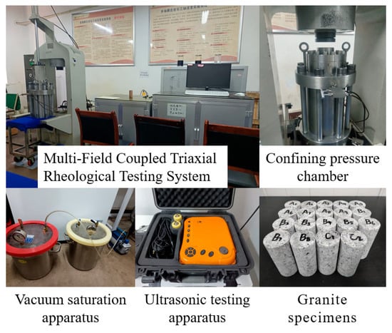
Figure 1.
Testing equipment and granite specimens.
In accordance with the stipulations outlined in ISRM, granite core specimens obtained from geological exploration boreholes at a hydropower station were processed into standardized cylindrical rock specimens measuring 50 mm in diameter and 100 mm in height. To maintain the integrity of the rock specimens and minimize variability in the test results, specimens exhibiting noticeable gaps and fissures on their surfaces, discernible to the naked eye, were excluded from the study. Additionally, secondary screening was conducted utilizing an ultrasonic detector, electronic balance, and vernier calipers to eliminate specimens with significant discrepancies in longitudinal wave velocity, mass, and dimensions. The selected rock specimens were subsequently subjected to a 24 h saturation process using a vacuum saturation apparatus.
The testing apparatus is capable of exerting a maximum confining pressure of 100 MPa and a seepage pressure of up to 60 MPa, operating under either flow control or pressure control modes. In this investigation, the pressure control mode was utilized, with the pressure sensor providing a control precision of ±0.01 MPa. Strain measurements were obtained using high-precision Linear Variable Differential Transformer (LVDT) sensors, featuring a measurement range of 10 mm and a control accuracy of ±0.001 mm. Prior to experimentation, all sensor acquisition systems underwent calibration to ensure accurate data output. For each experimental group, three rock specimens were selected. The statistical physical properties of these specimens are presented in Table 1.

Table 1.
Statistical table of physical parameters of rock specimens.
The dispersion of each indicator for the selected rock specimens was evaluated through the application of the coefficient of variation [45]. The findings demonstrated that the variation across all indicators for the rock specimens remained below 3%, suggesting that the dispersion of the chosen specimens satisfied the experimental criteria.
where is the coefficient of variation. is the standard deviation. is the mean value.
2.2. Test Method
Based on the results of in situ stress measurements obtained through hydraulic fracturing in boreholes, derived from geological exploration data, a confining pressure of 15 MPa has been established as the standard for this investigation. Considering the seepage challenges encountered in rock masses subjected to unloading within engineering applications, and acknowledging the practicality of performing laboratory experiments, seepage pressures of 2 MPa and 4 MPa were established as the conditions for the tests. Furthermore, to account for the substantial impact of unloading and the practical applicability of engineering rock masses, the unloading level of the rock specimens utilized in this experiment was consistently established at 70% [46]. The magnitude of unloading, denoted as D, is defined by Equation (2):
where is the specified value of confining pressure to be implemented. is the confining pressure value that aligns with the intended level of unloading. is the confining pressure value linked to the failure of the rock specimen during the unloading procedure.
Initially, both the standard triaxial compression test and the triaxial unloading test were conducted in the laboratory, utilizing a confining pressure of 15 MPa. In the triaxial compression test, the maximum strength of the rock specimen was recorded at 271.34 MPa. During the triaxial unloading test, the axial pressure was applied to 60% of the rock specimen’s peak strength, after which the confining pressure was reduced to 7.11 MPa at the point of failure of the rock specimen. Consequently, it can be inferred that the unloading range for this particular set of rock specimens, subjected to a confining pressure of 15 MPa, is approximately 8 MPa.
In light of the aforementioned rock strength characteristics, triaxial cyclic loading experiments were subsequently performed, and taking into account the influence of hydro-mechanical coupling. The experimental design comprised two distinct schemes: the first is the No Unloading group, which maintained a constant confining pressure of 15 MPa while applying seepage pressures of 2 MPa and 4 MPa, respectively. The second is the Unloading group, which also utilized a confining pressure of 15 MPa and seepage pressures of 2 MPa and 4 MPa, but incorporated a 70% unloading level.
The particular testing protocol involved a constant lower limit variable amplitude cyclic loading and unloading failure test. This methodology is designed to replicate the progressive damage and failure mechanisms of rock specimens by establishing a constant lower limit stress while incrementally increasing the stress amplitude. The stress path utilized in the testing is illustrated in Figure 2.
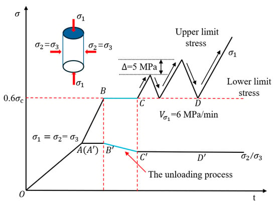
Figure 2.
Stress path diagram of cyclic loading.
(1) Phase OA (OA): axial pressure and confining pressure were initially applied at a rate of 2 MPa/min until a value of 4 MPa was attained. Following this, seepage pressure was incrementally applied at a rate of 0.5 MPa/min until it reached the specified target. Concurrently, the axial pressure and confining pressure were maintained at the initial application rate until the triaxial stress state achieved the designated hydrostatic pressure condition, specifically: == = 15 MPa.
(2) Phase AB (AB): In this phase, the axial stress is incrementally applied at a constant rate of 6 MPa/min, while maintaining a constant confining pressure, until it attains 60% of the peak strength observed in the conventional triaxial compression test.
(3) Phase BC (BC): Maintaining a constant axial pressure, the rock specimen underwent a 70% unloading process at a steady rate of 1 MPa/min, in accordance with the previously established unloading range. It is noteworthy that this particular test phase was excluded for the group that did not experience unloading.
(4) Phase CD (CD): involved conducting a cyclic loading test under constant confining pressure. The axial pressure was applied at a rate of 6 MPa/min. In this test, the upper limit stress for each cycle was incrementally increased by 5 MPa relative to the preceding cycle, while the lower limit stress was established at 60% of the peak strength of the rock specimen.
3. Analysis of Stress and Strain Results
3.1. Stress–Strain
The analysis presented herein utilizes the typical cyclic loading stress–strain curves of rock specimens subjected to varying seepage pressures and unloading conditions, as illustrated in Figure 3. The volumetric strain is determined by [47]. In the figure, the left portion of the horizontal axis corresponds to the expansion of rock volume. In addition, the initial point of the curve corresponds to the condition in which both the axial pressure and confining pressure have been applied to the designated hydrostatic pressure. The stress–strain values indicated in Figure 3 effectively categorize the process of force-induced deformation of the rock specimens into five distinct phases [48]:
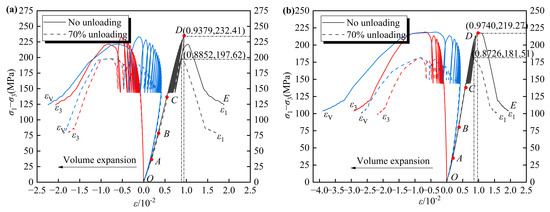
Figure 3.
Strain-stress curves under cyclic loading conditions. (a) Seepage pressure of 2 MPa; (b) Seepage pressure of 4 MPa.
(1) The fissure compaction phase (OA): the initial fractures within the rock specimen progressively undergo compaction and closure. Owing to the nonlinear nature of its compressive deformation, the resulting curve exhibits a slight upward concavity.
(2) The elastic deformation phase (AB): the particle skeleton structure of the rock specimen progressively attains a compact configuration. During this phase, elastic deformation predominates, leading to a linear relationship in the stress–strain curve.
(3) The stable development phase of fractures (BC): the rock specimen experiences progressive plastic deformation, during which internal micro-cracks initiate and progressively enlarge. This phenomenon results in the stress–strain characteristic curve exhibiting a gradual downward concave trend.
(4) The unstable development phase of fractures (CD): the implementation of cyclic loads induces continuous compression and expansion of the internal particle framework within the rock specimen, resulting in the rapid propagation of fractures. The phenomenon of stress concentration at the tips of these fractures facilitates their ongoing progressive development. Initially, the rock specimen experiences localized failure in regions characterized by comparatively weaker mechanical properties. This is subsequently followed by a redistribution of stress, which further instigates failure in additional areas of weakness. This sequence of events continues to advance until the rock’s capacity to bear load is ultimately compromised.
(5) The post-peak failure phase (DE): The swift propagation of fractures within rock specimens leads to the formation of a penetrating fracture surface, leading to a sharp reduction in rock strength, accompanied by a rapid increase in deformation.
Crack initiation stress , damage stress , and peak stress are three critical parameters for assessing the strength of rocks [49]. The characteristic strengths of rocks under varying seepage pressures and unloading conditions are presented in Table 2. The crack initiation, damage, and peak stress are represented by points B, C, and D in Figure 3, respectively. As indicated in Table 2, at a seepage pressure of 2 MPa without unloading, the crack initiation and damage stress of the rock are 33.52% and 58.89% of the peak stress, respectively (group 1). When the unloading effect is taken into account, the rock’s strength diminishes, resulting in an increase in crack initiation and damage stress to 39.39% and 69.08% of the peak stress, respectively (group 2). At a seepage pressure of 4 MPa without unloading, the crack initiation and damage stress are 35.00% and 61.04% of the peak stress, respectively (group 3). However, with the unloading effect, these values rise to 42.08% and 73.67% of the peak stress, respectively (group 4). This data suggests that elevated seepage pressure and the unloading effect exacerbate the damage process during cyclic loading of rocks, leading to increased crack initiation and damage stress. Furthermore, with increasing seepage pressure, the axial, radial, and volumetric strain values corresponding to crack initiation, damage, and peak stress progressively increase. The unloading phase occurs after the rock reaches its damage stress threshold, indicating that the unloading effect predominantly influences the peak stress and associated strain values of the rock.

Table 2.
Strength properties of granite under different Seepage pressures and unloading conditions.
An analysis of the stress–strain process curves presented in Figure 3a,b reveals that at seepage pressures of 2 MPa and 4 MPa, with an unloading level set at 70%, the capacity of the rock specimens to endure cycles prior to failure diminished from 18 and 14 to 9 and 6, respectively. Concurrently, the peak stress experienced a reduction of 14.97% and 17.22%, respectively. When both seepage pressure and unloading levels were increased simultaneously, the peak stress of the rock decreased by 21.90%. These data suggest that unloading exerts a pronounced detrimental effect on the strength characteristics of rocks, with this effect becoming increasingly severe as seepage pressure rises. The combined influence of these factors leads to a marked deterioration in the strength characteristics of the rock. The analysis indicates that during the unloading process, internal stress within the rock redistributes, resulting in stress concentration at the crack tips [2]. This phenomenon accelerates crack propagation, thereby compromising the mechanical characteristics and strength of the rock, making it more susceptible to failure under subsequent cyclic loading.
Furthermore, when analyzing the condition of 70% unloading under seepage pressures of 2 MPa and 4 MPa, the variance in peak strength of the rock specimens was found to be 302.59 MPa2 and 356.45 MPa2, respectively. Under an increased seepage pressure of 4 MPa, the variance in peak strength for the rock specimens was observed to be 43.16 MPa2 under fully unloaded conditions and 64.88 MPa2 under 70% unloading conditions. This suggests that unloading constitutes the primary mechanism driving the degradation of peak strength in rock specimens, as evidenced by an increase in variance spanning several orders of magnitude-from tens to hundreds-substantially surpassing the influence of seepage pressure. This finding indicates that unloading markedly intensifies the intrinsic heterogeneity of the rock mass, thereby producing considerable variability and unpredictability in strength. Moreover, elevated seepage pressure exacerbates this instability by augmenting the damage induced by unloading.
3.2. Axial Deformation
Figure 4 illustrates the stress-axial strain curves resulting from cyclic loading, as well as the evolution of axial residual strain in rock specimens subjected to varying seepage pressures and unloading conditions. Under conditions of cyclic loading and unloading, the stress–strain curve of rock commonly demonstrates hysteresis loops, characterized by a divergence between the unloading and loading trajectories. This behavior leads to the accumulation of residual strain within the rock after each loading cycle, quantified as the strain differential between the termination point of the unloading curve and the initiation point of the subsequent loading curve. The data indicates that, under cyclic loading conditions, an increase in axial stress levels leads to a corresponding increase in both the intervals and areas of the hysteresis loops, as well as an escalation in residual deformation. Furthermore, as the number of loading cycles increases, the axial residual strain exhibits a nonlinear and accelerating growth pattern. As the rock specimen approaches failure, the rate of development of axial residual strain intensifies.
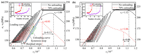
Figure 4.
Stress-axial strain curve under cyclic loading conditions. (a) Seepage pressure of 2 MPa; (b) Seepage pressure of 4 MPa.
A comparative analysis of Figure 4a,b reveals that, under seepage pressures of 2 MPa and 4 MPa, the axial strain at failure of rock specimens, after accounting for a 70% unloading effect, decreased from 1.06 × 10⁻² and 1.12 × 10⁻² to 0.93 × 10⁻² and 1.06 × 10⁻², respectively. Additionally, it was observed that the axial deformation of the rock specimens increased with rising seepage pressure. This analysis indicates that the unloading effect results in a diminished load-bearing capacity of the rock, which subsequently leads to failure occurring at fewer cycles and lower levels of axial stress. Consequently, the axial deformation exhibits a decreasing trend. Additionally, the elevation of seepage pressure contributes to a further reduction in effective confining pressure. Concurrently, elevated seepage pressure within the rock specimen enhances the deterioration effects of cyclic loading, thereby increasing the axial deformation of the rock specimen.
Moreover, the dynamic evolution of axial stress resulting from cyclic loading and unloading can induce considerable alterations in the axial deformation characteristics of the unloaded rock mass. Such alterations are particularly evident in the form of residual strain accumulation and a decrease in the elastic modulus [6]. This mechanical process instigates the progressive development and interconnection of the fracture network within the rock mass, ultimately compromising its structural integrity and diminishing its load-bearing capacity.
3.3. Radial Deformation
Figure 5 illustrates the stress-radial strain curves associated with cyclic loading, as well as the evolution of radial residual strain under varying seepage pressures and unloading conditions. As depicted in Figure 5, the radial residual strain exhibits a nonlinear and accelerating growth pattern. Furthermore, when accounting for the unloading effect, there is a notable increase in the overall residual strain of the rock.
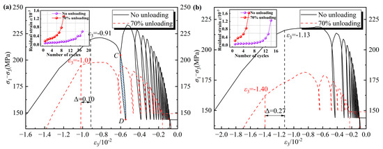
Figure 5.
Stress-radial strain curve under cyclic loading conditions. (a) Seepage pressure of 2 MPa; (b) Seepage pressure of 4 MPa.
Figure 5 illustrates that, under seepage pressures of 2 MPa and 4 MPa, the radial deformation of the rock specimen at the point of failure increased by 0.10 × 10⁻² and 0.27 × 10⁻², respectively, when accounting for the unloading effect. The analysis indicates that during the unloading process, the stress trajectory of the rock transitions from a loading state to an unloading state. The reduction in confining pressure extremely diminishes the radial constraint capacity of the rock, thereby exacerbating the damage effects of subsequent cyclic loads and rendering the rock more susceptible to radial deformation.
By conducting a comparative analysis of Figure 5a,b, when considering only the influence of seepage pressure, the peak strain differences for the rock specimens are 0.22 × 10⁻² and 0.39 × 10⁻², respectively. The unloading effect significantly amplifies the impact of seepage pressure, resulting in a 77.27% increase in the radial deformation of the rock after unloading, as compared to the deformation observed in the absence of unloading. The analysis indicates that rock specimens experience increased damage and a higher incidence of fractures when subjected to unloading conditions. During this phase, the proliferation of internal seepage channels renders the rock specimens more susceptible to seepage pressure [50]. Consequently, under unloading conditions, the rock specimens demonstrate pronounced radial deformation characteristics in response to rising seepage pressure.
3.4. Volume Deformation
Figure 6 illustrates the stress versus volumetric strain curves associated with cyclic loading, as well as the evolution of volumetric residual strain in rock specimens subjected to varying seepage pressures and unloading conditions.
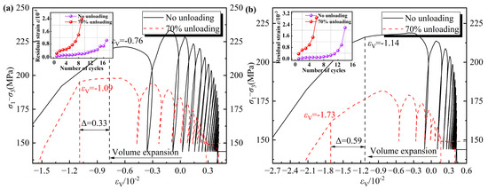
Figure 6.
Stress-volume strain curve under cyclic loading conditions. (a) Seepage pressure of 2 MPa; (b) Seepage pressure of 4 MPa.
As illustrated in Figure 6, during the initial phase of axial compression loading, the internal pore structure of the rock specimen undergoes compaction, leading to a reduction in volume as axial pressure increases. Once the applied load surpasses the rock’s initiation stress, micro-cracks within the material begin to propagate, resulting in an increase in volume [16]. In the early phase of axial unloading, the elastic deformation recovers, causing the internal pores and micro-cracks to re-open, which in turn leads to an improvement in volume as axial pressure decreases. As the axial pressure continues to diminish, the volume of the rock begins to contract due to the influence of the radial confining force exerted by the confining pressure. Moreover, as a result of the plastic deformation experienced by the rock specimen during the axial compression loading process, the volume does not completely revert to its original state upon unloading. Consequently, the total deformation of the rock specimen exhibits a progressive increase.
A comparison of Figure 6a,b indicates that, when subjected to seepage pressures of 2 MPa and 4 MPa, and after accounting for a 70% unloading effect, the volume strain of the rock at failure increases from 0.76 × 10⁻² and 1.14 × 10⁻² to 1.09 × 10⁻² and 1.73 × 10⁻², respectively. The analysis indicates that the unloading effect facilitates the formation and interconnection of the internal fracture network within the rock, resulting in a reduction in its strength and stiffness. As a result, when the rock specimen experiences failure under subsequent cyclic loads, there is an increase in volume strain. Furthermore, as the seepage pressure escalates, the pore water pressure within the rock specimen also increases, which further facilitates the volumetric expansion of the rock specimen.
4. Analysis of Seepage Results
4.1. Peak Intensity Permeability
This research utilized the steady-state seepage method [51] to assess the permeability of rock materials. A constant water pressure boundary condition was established at the upstream end of the rock specimen. Once the seepage achieved a steady state, the volume of water passing through the rock specimen per unit time remained unchanged. By integrating the hydraulic gradient with fundamental physical parameters, the seepage characteristics can be determined. The formula for calculation is as follows [52]:
where is the mean permeability of the rock, m2. is the viscosity coefficient of the fluid, measured at 1.005 × 10⁻³ Pa · s. is the height of the rock specimen, m. is the volume of the fluid, m3. is the cross-sectional area of the rock specimen, m2. is the difference in seepage pressure, Pa. is the elapsed time, s.
Utilizing the principles of steady-state seepage, the permeability of the rock at its maximum strength was assessed through Equation (3), as detailed in Table 3. Table 3 illustrates that the varying magnitudes of seepage pressure and unloading are the primary factors contributing to the discrepancies observed in rock permeability. By establishing a baseline with a seepage pressure of 2 MPa and an unloading level of 0%, the mean range of permeability variation under various conditions was calculated. The findings indicate that an increase in seepage pressure from 2 MPa to 4 MPa leads to a 118.70% improvement in rock permeability, in contrast to a 250.66% increase observed under a 70% unloading magnitude. This suggests that a 70% unloading magnitude exerts a more significant detrimental effect on the integrity of rock. In the analysis of the concurrent impacts of a seepage pressure of 4 MPa and a 70% unloading level, it is noted that the enhancement in rock permeability reaches a value of 446.70%, which exceeds the total increase recorded from the preceding two factors. Consequently, the effect of seepage pressure and unloading on rock integrity does not conform to a straightforward linear superposition model. Instead, their simultaneous influence markedly intensifies the extent of rock damage and degradation.

Table 3.
Comparison of permeability at peak strength of granite.
Research indicates that permeability is indicative of the ease with which fluids traverse the pore structure of rocks. During the process of unloading, internal fractures within rock specimens tend to develop and propagate rapidly. Following the expansion of these fractures, the incorporation of water molecules becomes more feasible, which subsequently increases the surface area of internal seepage channels within the rock specimens, thereby enhancing permeability. The elevation of seepage pressure results in a heightened seepage rate within the rock specimen, consequently exacerbating the extent of damage to the seepage channels. Consequently, under the dual impact of high seepage pressure and unloading, the permeability of engineering rock mass is likely to exhibit a marked increase, while their load-bearing capacity is significantly diminished. Furthermore, in the evaluation of deep unloaded rock masses stability in engineering applications, it is essential to systematically analyze the spatial distribution characteristics of rock mass structural planes, as well as the impact of the extent of joint and fissure network development on permeability. This comprehensive assessment is crucial for ensuring the safety and longevity of the project.
4.2. Seepage Rate and Seepage Volume
Figure 7 illustrates the seepage rate and seepage volume of rock specimens subjected to varying seepage pressures and unloading conditions during cyclic loading. Taking rock specimen 2 as a case study, in the OA section, during the initial phase of seepage pressure application, the rock is in the fissure compaction phase. The internal seepage pathways within the rock specimen exhibited a contraction, resulting in a gradual reduction in the seepage rate, and the volume of seepage experienced a slow increase. In the AB section, as the axial stress level escalates, the rock specimen progressively transitions into the stable development phase of fractures, during which the seepage rate and the volume of seepage demonstrate a stable increase. In the BC section, under the sustained influence of elevated stress, the rock specimen enters the unstable development phase of fractures. This results in the continuous expansion of seepage channels, with both the seepage rate and volume curves exhibiting a rapid upward trend. Furthermore, as the seepage pressure and unloading magnitude intensify, the variation in the seepage rate of the rock specimen reveals a pronounced nonlinear acceleration characteristic, accompanied by a significant reduction in bearing time.
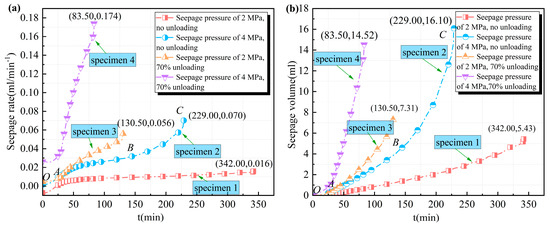
Figure 7.
The seepage characteristic curve under cyclic loading. (a) Seepage rate; (b) Seepage volume.
A comparative analysis of Figure 7a,b reveals a notable correlation between the seepage characteristics and bearing durations of rock specimens subjected to varying seepage pressures and unloading conditions. Specifically, rock specimen 1, which was tested under a lower seepage pressure without any unloading, exhibited a relatively low seepage rate and seepage volume, achieving a bearing time of 342.00 min under cyclic loading. In contrast, rock specimen 2, subjected to a seepage pressure of 4 MPa, demonstrated the highest seepage volume; however, its seepage rate remained comparatively low, resulting in a bearing time of only 229.00 min. Conversely, rock specimens 3 and 4, despite having lower seepage volumes than specimen 2, experienced a marked increase in seepage rate due to the unloading effect, leading to a significant decrease in bearing times of 130.50 min and 83.50 min, respectively. These findings suggest that unloading effect may compromise the mechanical integrity of engineering rock mass and diminish its impermeability, thereby increasing its susceptibility to instability and failure under seepage pressure.
4.3. The Dynamic Evolution Process of Permeability
The permeability evolution laws of rock specimens subjected to varying seepage pressures and unloading conditions during cyclic loading phases, in relation to stress and axial strain, are illustrated in Figure 8. In the presented figure, the variable k denotes the ratio between the difference in axial strain and the difference in permeability observed at points A and B. This parameter serves to quantify the rate at which rock permeability varies as a function of axial strain. An elevated value of k corresponds to a more rapid change in permeability.
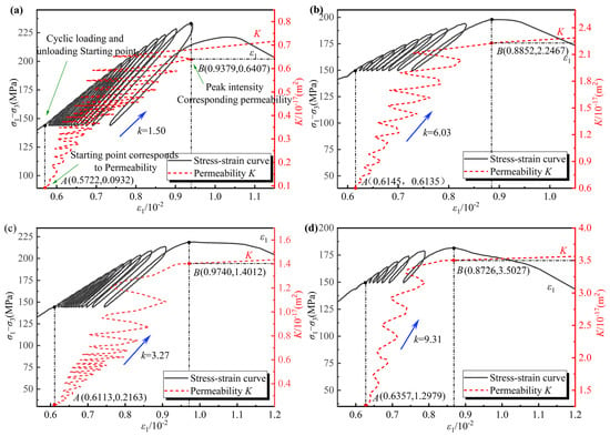
Figure 8.
The dynamic evolution of permeability during cyclic loading. (a) Seepage pressure of 2 MPa, no unloading; (b) Seepage pressure of 2 MPa, 70% unloading; (c) Seepage pressure of 4 MPa, no unloading; and (d) Seepage pressure of 4 MPa, 70% unloading.
As illustrated in Figure 8, the permeability of the material demonstrates a pronounced path dependence in relation to stress and axial strain under cyclic loading conditions, exhibiting a characteristic of cyclic increase. The findings indicate that with repeated cycles of loading and unloading axial stress, the seepage channels within the rock specimen experience periodic expansions and contractions, which result in ongoing fluctuations in the seepage rate. Furthermore, during each cycle of axial stress, there is an irreversible increase in permeability, and this incremental effect accumulates progressively with the increasing number of cyclic loads, ultimately leading to a sustained rise in permeability.
As the intensity of seepage pressure and unloading increases, the frequency with which rock specimens can endure cyclic loading diminishes, concurrently with an improvement in the rate of permeability growth, as evidenced by the increase in the k value depicted in Figure 8. Research indicates that elevated seepage pressure diminishes the effective stress within rocks. When the effective stress falls below the critical threshold for rock fractures, previously closed fractures may reopen, and new fractures may form, thereby enlarging the seepage pathways and enhancing permeability [36]. Additionally, when the unloading effect is taken into account, the internal structure of the rock sustains damage, leading to an increase in both the connectivity and aperture of fractures. This enlargement of seepage channels consequently results in heightened permeability. Furthermore, during the cyclic loading of axial stress, the internal stress state of the rock experiences periodic fluctuations. This dynamic interaction exacerbates the expansion and interconnection of fractures, facilitating the gradual development of a cohesive seepage network within the rock, which in turn accelerates the rate of permeability increase.
5. Analysis of Deformation and Fracture Results
5.1. Elastic Modulus and Poisson’s Ratio
Under conditions of cyclic loading, the mean value of the unloading elastic modulus serves as a critical parameter for the characterization of the elastic modulus of rock materials. The unloading elastic modulus is ascertained by calculating the ratio of axial stress to axial strain at the upper and lower endpoints of the hysteresis loop, specifically represented by the slope of the line connecting points A and B on the hysteresis loop, as illustrated in Figure 4a. Furthermore, the Poisson’s ratio of rock can be ascertained by examining the ratio of the absolute value of radial strain to axial strain. This is achieved by calculating the ratio of the strain difference between the upper and lower endpoints of the associated hysteresis loops, as indicated in Figure 4a and Figure 5a. The formula for this calculation is provided as follows [48]:
where and are the axial stress values associated with the upper and lower limits of the hysteresis loop, respectively. and are the axial strain values corresponding to these upper and lower endpoints, respectively. and are the radial strain values associated with the upper and lower endpoints, respectively.
The unloading elastic modulus and Poisson’s ratio curves, derived from Equations (4) and (5), are presented in Figure 9a and b, respectively.
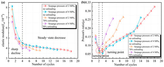
Figure 9.
Schematic diagram of cyclic loading damage evolution. (a) Unloading elastic modulus; (b) Poisson’s ratio.
As the number of cyclic loads cycles increases, the elastic modulus can be categorized into two distinct phases: an initial sharp decline followed by a steady-state decrease. Conversely, the Poisson’s ratio exhibits an initial sharp decrease, which is subsequently followed by a steady increase. When the unloading effect is taken into account, the inflection point of the Poisson’s ratio curve appears to advance. This study indicates that during the early phase of cyclic loading, pre-existing fractures within the rock specimen are compressed and filled, leading to a rapid increase in vertical deformation. At this phase, the stress amplitude remains relatively low, leading to a sudden reduction in the elastic modulus. Simultaneously, the radial deformation develops at a slower rate under lower stress amplitudes, which contributes to the observed decline in Poisson’s ratio. As the upper limit stress level continues to rise, once the stress amplitude reaches the yield threshold of the rock, the rate of radial deformation begins to surpass that of axial deformation, leading to a gradual deterioration of the elastic modulus and a steady improvement in Poisson’s ratio. Furthermore, the unloading effect exacerbates the internal damage within the rock specimen, causing it to reach its yield threshold sooner, which in turn results in an earlier appearance of the inflection point in Poisson’s ratio deformation curve.
5.2. Mean Residual Deformation
Figure 10 illustrates the mean residual strain prior to the peak during the cyclic loading phases under varying seepage pressures and unloading conditions. The mean residual strain is determined by the ratio of the cumulative residual strain observed prior to the peak of cyclic loading to the number of cyclic loads. This approach facilitates a more effective comparison of axial, radial, and volumetric deformations of rocks subjected to varying seepage pressures and unloading conditions throughout the cyclic loading process.
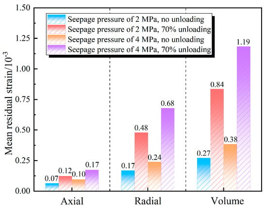
Figure 10.
Mean residual strain before the peak.
As illustrated in Figure 10, as the intensity of seepage pressure and unloading escalates, there is a corresponding increase in the axial, radial, and volumetric average residual strains observed in the rock specimens. Furthermore, the radial and volumetric average residual strains are significantly higher than the axial strains. This observation indicates that elevated seepage pressure and the unloading effect exacerbate the deterioration caused by cyclic loading on the rocks, leading to a multiplication in the mean residual strain experienced by the rocks during each cycle of loading. This damage effect appears to have a more pronounced influence on the radial deformation of the rocks.
Research demonstrates that an improvement in seepage pressure adversely affects the overall strength and stiffness of rock, rendering it more susceptible to residual deformation when subjected to cyclic loads. The application of stress and hydraulic boundary conditions at the upper section of the rock specimen facilitates the development and intensification of vertical fissures, thereby exacerbating the radial residual deformation of the rock during cyclic loads. Furthermore, during the unloading phase, the radial confining force acting on the rock diminishes, and the rapid release of stress results in heightened radial residual deformation under cyclic loads, which subsequently contributes to a notable radial expansion phenomenon.
5.3. Macroscopic Fracture Characteristics
Figure 11 illustrates the macroscopic fracture characteristics of granite subjected to varying seepage pressures and unloading conditions. Analyzing the fracture distribution reveals that the rock specimens exhibit multiple macroscopic fracture damage, with an observed increase in the number of fractures corresponding to higher seepage pressures and greater unloading magnitudes. This suggests that elevated seepage pressure and the unloading effect play a crucial role in the formation of rock fractures. Li et al. [53,54] demonstrated that the macroscopic fracture behavior of rocks is predominantly governed by microfracture mechanisms initiated by interactions among the constituent particles of the rock. Consequently, from a microscopic standpoint, the loading process leading to rock failure can be characterized as the nucleation, growth, and eventual propagation of microcracks within the rock matrix.
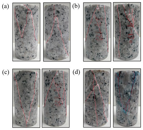
Figure 11.
Macroscopic fracture morphology of rock specimens under cyclic loading. (a) Seepage pressure of 2 MPa, no unloading; (b) Seepage pressure of 2 MPa, 70% unloading; (c) Seepage pressure of 4 MPa, no unloading; and (d) seepage pressure of 4 MPa, 70% unloading.
At a confining pressure of 15 MPa, the fracture characteristics of granite exhibit notable variations under different seepage pressures and unloading conditions. In the absence of unloading, the cyclic axial loading of the rock specimen results in the continuous closure and opening of internal micro-cracks. This dynamic evolution of the internal pore and fracture structure ultimately culminates in the formation of a V-shaped shear fracture surface, accompanied by a limited number of secondary shear cracks, as illustrated in Figure 11a,c. Additionally, under conditions of seepage pressure of 2 MPa and 70% unloading, the diminished radial confinement capacity results in an increase in the number of vertical fractures within the rock. This results in tensile splitting failure that occurs nearly parallel to the axial direction, with multiple secondary shear cracks emerging on the surface, as depicted in Figure 11b. Furthermore, at a seepage pressure of 4 MPa and 70% unloading, the internal seepage rate of the rock specimen is enhanced, which accelerates fracture development. This condition leads to an increase in both the failure pressure of the specimen and the crack aperture, with the rock specimen exhibiting a pronounced dilatancy phenomenon, as shown in Figure 11d.
In summary, under conditions of elevated confining pressure and high seepage pressure, V-shaped conjugate shear fracture surfaces are likely to develop during the cyclic loading failure of granite, with a limited occurrence of secondary shear cracks. When accounting for the effects of unloading damage, the formation of through-going tensile fracture surfaces is more probable, extending from the top to the bottom of the rock mass, and is associated with a greater prevalence of secondary shear cracks. Furthermore, an analysis of the volume deformation of the rock indicates that the unloaded rock mass is more susceptible to the propagation of through-going fractures in a high seepage pressure environment following cyclic loading. This phenomenon results in radial expansion of the rock mass and the emergence of cross-fracture characteristics.
6. Discussion
In deep, high-stress, and high-permeation pressure conditions, the stability of engineering rock masses is influenced by the combined effects of excavation-induced unloading disturbances and seepage erosion. Consequently, performing cyclic loading and unloading experiments on rock specimens subjected to varying degrees of unloading and seepage pressure is of considerable importance. Such investigations facilitate a comprehensive understanding of the damage progression and alterations in seepage characteristics of rocks throughout the unloading process, thereby offering an empirical foundation for relevant engineering applications.
According to prior research, sandstone predominantly experiences shear failure with limited tensile cracking when subjected to seepage pressure and unloading conditions [49]. In contrast, the present study reveals that granite undergoes more severe failure under similar conditions, characterized by a combined tensile-shear failure mechanism. Furthermore, under a confining pressure of 15 MPa and 60% unloading conditions, with pore pressure varying between 2 MPa and 4 MPa, the peak strength of sandstone was observed to decrease by 2.78%, while the radial strain exhibited an increase of 145.67% [48]. In the case of the granite analyzed in the present study, subjected to a confining pressure of 15 MPa and 70% unloading conditions, an increase in pore pressure from 2 MPa to 4 MPa resulted in a reduction in peak strength by 8.15% and an increase in radial strain by 38.61%. The analysis reveals that granite is categorized as a hard rock characterized by low porosity, whereas sandstone is identified as a soft rock with high porosity. Consequently, under comparable conditions, granite displays substantially lower deformation despite its relatively higher strength, while sandstone experiences a comparatively modest decrease in strength but undergoes considerable deformation. These findings imply that during the excavation of engineering rock masses, it is imperative to focus on mitigating rock burst hazards associated with hard rocks and managing the substantial deformation of surrounding rock, typically induced by soft rocks.
Although this study has examined the mechanical behavior and seepage evolution characteristics of unloaded rock specimens subjected to high seepage pressure environments and cyclic loading-unloading regimes, the influence of cyclic loading on the strengthening or weakening of unloaded rock specimens remains inconclusive. This issue warrants further investigation through monotonic loading tests conducted under identical conditions. Consequently, future research should implement systematic monotonic loading experiments under consistent initial conditions and seepage pressure levels, enabling quantitative comparisons with cyclic loading outcomes across multiple parameters, including strength, deformation, and energy accumulation and dissipation characteristics. Such comprehensive analyses will provide a more robust foundation for assessing the dynamic stability of deep engineering rock masses under coupled hydraulic-mechanical conditions.
Moreover, as this study did not utilize microscopic methods, including electron microscopy or computed tomography scanning, for observational purposes, the analysis of microcrack propagation induced by unloading and seepage pressure is subject to certain limitations. This aspect warrants further exploration in future research endeavors.
7. Conclusions
An experimental investigation was conducted on the cyclic loading and unloading behavior of the unloaded granite, specifically under conditions of hydraulic coupling. This study also examined the evolution of mechanical properties, seepage characteristics, and fracture failure mechanisms, integrating analyses of stress–strain behavior, permeability changes, and crack propagation patterns. The principal findings of the research are summarized as follows:
- 1.
- Under seepage pressures of 2 MPa and 4 MPa, the peak stress of rock specimens was observed to decrease by 14.97% and 17.22%, respectively, following 70% unloading. When subjected concurrently to a seepage pressure of 4 MPa and 70% unloading, the peak stress exhibited a reduction of 21.90%. These findings suggest that the degradation of rock strength resulting from the combined effects of seepage pressure and unloading does not conform to a simple linear superposition relationship.
- 2.
- When accounting for unloading effects, the radial peak strain of the rock specimens increased by 0.10 × 10⁻² and 0.27 × 10⁻² under seepage pressures of 2 MPa and 4 MPa, respectively. Considering the influence of seepage pressure, the difference in radial peak strain between the specimens without unloading and those subjected to 70% unloading increased by 0.22 × 10⁻² and 0.39 × 10⁻², respectively. These findings indicate that both unloading and seepage pressure significantly contribute to lateral dilation in the rock specimens, with seepage pressure exerting a more pronounced effect.
- 3.
- Variations in seepage pressure and unloading conditions are primary factors contributing to the discrepancies observed in rock permeability. Furthermore, the magnitude of permeability is inversely related to the number of cycles of loads that the rock can endure. When subjected to cyclic loads, permeability exhibits a distinct path dependence in relation to stress and axial strain, demonstrating a characteristic of cyclic increase.
- 4.
- Under conditions of increased confining pressure and seepage pressure, the formation of V-shaped conjugate shear fracture surfaces is probable during the cyclic loading failure of granite. The unloading effect influences the failure mechanism of the rock, resulting in a shear-tensile composite failure characteristic. In deep underground engineering, it is essential to optimize the support parameters for the excavation-unloaded rock mass to enhance the support system’s adaptability to composite failure modes.
- 5.
- The present study has not yet incorporated microscopic analyses, such as scanning electron microscopy, which limits the ability to thoroughly examine microstructural features, including crack propagation. Additionally, the experimental design was confined to only two seepage pressure conditions. Future research endeavors should consider broadening the range of seepage pressure parameters and integrating energy-based and acoustic emission methodologies to facilitate a more comprehensive, multidimensional assessment of rock damage.
Author Contributions
Conceptualization, K.W. and X.C.; Methodology, K.W., X.C., S.G., L.C. and K.N.; Formal analysis, K.W., L.C. and S.G.; Data curation, K.W., K.N. and S.G.; Writing—original draft, K.W. and X.C.; Writing—review and editing, S.G., L.C. and K.N.; Supervision, X.C. and S.G.; Project administration, X.C.; Funding acquisition, X.C. All authors have read and agreed to the published version of the manuscript.
Funding
This study was financially supported by The Joint Funds of the National Natural Science Foundation of China, grant number U1965107.
Institutional Review Board Statement
Not applicable.
Informed Consent Statement
Not applicable.
Data Availability Statement
The dataset used to support the findings of this study is available from the corresponding author upon request.
Conflicts of Interest
The authors declare no conflicts of interest.
References
- Ma, Y.G.; Yu, C.; Li, H.B.; Ma, X.D.; Li, S.J. Comparison Study on Damage Characteristics of Deeply Buried Granite Under Triaxial Cyclic Loading and Unloading. Rock Mech. Rock Eng. 2024, 58, 1591–1616. [Google Scholar] [CrossRef]
- Chen, X.Z.; Bai, Y.N.; Chen, L.L.; Ma, B.; Wang, W.R.; Gong, S. Experimental study on mechanical properties of excavated unloaded rock mass under high seepage pressure and cyclic loading and unloading environments. Chin. J. Geotech. Eng. 2024, 46, 737–745. [Google Scholar] [CrossRef]
- Liu, Y.; Dai, F.; Fan, P.X.; Xu, N.W.; Dong, L. Experimental Investigation of the Influence of Joint Geometric Configurations on the Mechanical Properties of Intermittent Jointed Rock Models Under Cyclic Uniaxial Compression. Rock Mech. Rock Eng. 2017, 50, 1453–1471. [Google Scholar] [CrossRef]
- Momeni, A.; Karakus, M.; Khanlari, G.R.; Heidari, M. Effects of cyclic loading on the mechanical properties of a granite. Int. J. Rock Mech. Min. Sci. 2015, 77, 89–96. [Google Scholar] [CrossRef]
- Meng, Q.B.; Liu, J.F.; Ren, L.; Pu, H.; Chen, Y.L. Experimental study on rock strength and deformation characteristics under triaxial cyclic loading and unloading conditions. Rock Mech. Rock Eng. 2021, 54, 777–797. [Google Scholar] [CrossRef]
- Zhu, X.Y.; Chen, X.D.; Dai, F. Mechanical Properties and Acoustic Emission Characteristics of the Bedrock of a Hydropower Station under Cyclic Triaxial Loading. Rock Mech. Rock Eng. 2020, 53, 5203–5221. [Google Scholar] [CrossRef]
- Fuenkajorn, K.; Phueakphum, D. Effects of cyclic loading on mechanical properties of Maha Sarakham salt. Eng. Geol. 2010, 112, 43–52. [Google Scholar] [CrossRef]
- Erarslan, N.; Williams, D. Investigating the effect of cyclic loading on the indirect tensile strength of rocks. Rock Mech. Rock Eng. 2012, 45, 327–340. [Google Scholar] [CrossRef]
- Chen, Z.Q.; Ma, C.C.; Li, T.B.; He, C. Experimental investigation of the failure mechanism of deep granite under high seepage water pressure and strong unloading effect. Acta. Geotech. 2022, 17, 5009–5030. [Google Scholar] [CrossRef]
- Xie, H.P. Research Framework and Anticipated Results of Deep Rock Mechanics and Mining Theory. Chin. J. Adv. Eng. Sci. 2017, 49, 1–16. [Google Scholar] [CrossRef]
- Yang, S.Q.; Huang, Y.H.; Tang, J.Z. Mechanical, acoustic, and fracture behaviors of yellow sandstone specimens under triaxial monotonic and cyclic loading. Int. J. Rock Mech. Min. 2020, 130, 104268. [Google Scholar] [CrossRef]
- Zhang, A.L.; Xie, H.P.; Zhang, R.; Gao, M.Z.; Xie, J.; Jia, Z.Q.; Ren, L.; Zhang, Z.T. Mechanical properties and energy characteristics of coal at different depths under cyclic triaxial loading and unloading. Int. J. Rock Mech. Min. 2023, 161, 105271. [Google Scholar] [CrossRef]
- Miao, S.J.; Liu, Z.J.; Zhao, X.G.; Ma, L.; Zheng, Y.W.; Xia, D.H. Plastic and damage energy dissipation characteristics and damage evolution of Beishan granite under triaxial cyclic loading. Int. J. Rock Mech. Min. 2024, 174, 105644. [Google Scholar] [CrossRef]
- Chen, G.B.; Li, Y.; Li, T.; Zhang, G.H. Deterioration law of intermittent jointed sandstone mechanical properties under water–rock interaction. Acta. Geophys. 2022, 70, 1923–1935. [Google Scholar] [CrossRef]
- Sun, X.M.; Ding, J.X.; He, L.S.; Shi, F.K.; Zhang, Y.; Miao, C.Y.; Zhang, J. Mechanical properties and energy evolution law of water bearing sandstone under cyclic loading. J. Mt. Sci. 2024, 21, 3913–3929. [Google Scholar] [CrossRef]
- Shen, R.X.; Chen, T.Q.; Li, T.X.; Li, H.R.; Fan, W.J.; Hou, Z.H.; Zhang, X. Study on the effect of the lower limit of cyclic stress on the mechanical properties and acoustic emission of sandstone under cyclic loading and unloading. Theor. Appl. Fract. Mech. 2020, 108, 102661. [Google Scholar] [CrossRef]
- Yang, B.B.; He, M.M.; Chen, Y.S. Experimental study of nonlinear damping characteristics on granite and red sandstone under the multi-level cyclic loading-unloading triaxial compression. Arab. J. Geosci. 2020, 13, 211–213. [Google Scholar] [CrossRef]
- Zhang, B.C.; Liang, Y.P.; Zhao, Z.Y.; Zou, Q.L.; Zheng, H.L.; Ning, Y.H.; Kong, F.J.; Ran, Q.C. Effect of stress amplitude on mechanical and acoustic emission of sandstone under constant–cyclic loading. Bull. Eng. Geol. Environ. 2023, 82, 284. [Google Scholar] [CrossRef]
- Xue, F.; Lin, Z.Q.; Wang, T.Z. Experimental study on effects of cyclic loading paths on cracking behavior and fracture characteristics of granite. Eng. Fract. Mech. 2024, 295, 109761. [Google Scholar] [CrossRef]
- Liu, M.X.; Liu, E.L. Dynamic mechanical properties of artificial jointed rock samples subjected to cyclic triaxial loading. Int. J. Rock Mech. Min. 2017, 98, 54–66. [Google Scholar] [CrossRef]
- Xu, J.; Sun, S.H.; Luo, S. Damage and energy evolution characteristics of pre-cracked sandstone under multi-stage amplitude-increasing cyclic loading. Theor. Appl. Fract. Mech. 2025, 139, 105011. [Google Scholar] [CrossRef]
- White, J.A. Anisotropic damage of rock joints during cyclic loading: Constitutive framework and numerical integration. Int. J. Numer. Anal. Met. 2014, 38, 1036–1057. [Google Scholar] [CrossRef]
- Fathi, A.; Moradian, Z.; Rivard, P.; Ballivy, G. Shear mechanism of rock joints under prepeak cyclic loading condition. Int. J. Rock Mech. Min. Sci. 2016, 83, 197–210. [Google Scholar] [CrossRef]
- Zhang, W.; Zhang, B.L.; Guo, W.Y. Study on the mechanism of energy evolution and bearing degradation in pre-cracked sandstone under non uniform cyclic loading. Theor. Appl. Fract. Mech. 2024, 132, 104472. [Google Scholar] [CrossRef]
- Aliha, M.R.M.; Mahdavi, E.; Ayatollahi, M.R. Statistical analysis of rock fracture toughness data obtained from different chevron notched and straight cracked mode I specimens. Rock Mech. Rock Eng. 2018, 51, 2095–2114. [Google Scholar] [CrossRef]
- Gao, S.; Wu, F.; Gao, R.B.; Li, C.B.; Chen, J. Damage behavior of red sandstone subjected to multi-stage constant-amplitude cyclic loading. J. Rock Mech. Geotech. Eng. 2025, 17, 6548–6570. [Google Scholar] [CrossRef]
- Zhang, J.R.; Luo, Y.; Gong, H.L.; Zhang, X.Q.; Zhao, S.K. Characteristics of Energy Evolution and Failure Mechanisms in Sandstone Subject to Triaxial Cyclic Loading and Unloading Conditions. Appl. Sci. 2024, 14, 8693. [Google Scholar] [CrossRef]
- Duan, X.L.; Wang, W.; Liu, S.F.; Cao, Y.J.; Zheng, Z.; Zhu, Q.Z. Experimental investigation on mechanical behavior, energy evolution and gas permeability of anisotropic phyllite subjected to triaxial compression and cyclic loading. Geomech. Energy. Environ. 2023, 35, 100483. [Google Scholar] [CrossRef]
- Lin, H.; Liu, J.F.; Yang, J.X.; Ran, L.N.; Ding, G.S.; Wu, Z.D.; Lyu, C.; Bian, Y. Analysis of damage characteristics and energy evolution of salt rock under triaxial cyclic loading and unloading. J. Energy. Storage. 2022, 56, 104379. [Google Scholar] [CrossRef]
- Akdag, S.; Karakus, M.; Nguyen, G.D.; Taheri, A.; Bruning, T. Evaluation of the propensity of strain burst in brittle granite based on postpeak energy analysis. Undergr Space 2021, 6, 1–11. [Google Scholar] [CrossRef]
- Chen, Y.C.; Zhao, Z.K.; Guo, J. Precursors of rock failure under cyclic loading and unloading: From the perspective of energy and acoustics. Eng. Fail. Anal. 2024, 166, 108860. [Google Scholar] [CrossRef]
- Jia, M.T.; Liu, P.F.; Li, S.D.; Guo, S.Q. Mechanical properties and acoustic emission characteristics of granite under discontinuous multilevel fatigue loading. Bull. Eng. Geol. Environ. 2025, 84, 281. [Google Scholar] [CrossRef]
- Wang, Y.; Li, C.H.; Liu, H.; Han, J.Q. Fracture failure analysis of freeze–thawed granite containing natural fracture under uniaxial multi-level cyclic loads. Theor. Appl. Fract. Mech. 2020, 110, 102782. [Google Scholar] [CrossRef]
- Wang, Y.; Zhang, B.; Gao, S.H.; Li, C.H. Investigation on the effect of freeze-thaw on fracture mode classification in marble subjected to multi-level cyclic loads. Theor. Appl. Fract. Mech. 2021, 111, 102847. [Google Scholar] [CrossRef]
- Duan, X.L.; Wang, W.; Cao, Y.J.; Zhang, Q.; Li, W.X.; Zhu, Q.Z.; Wang, R.B. Effects of pore pressure on mechanical behavior of Xiyu conglomerate subjected to loading-unloading cycles with varied amplitude. J. Rock Mech. Geotech. Eng. 2025. [Google Scholar] [CrossRef]
- Qu, X.; Xu, W.; Ma, H.F.; Guo, Z.F. Experimental study on mechanical and permeability properties of subsea granite under cyclic loading with different seepage pressures. Bull. Eng. Geol. Environ. 2025, 84, 70. [Google Scholar] [CrossRef]
- Ning, Z.X.; Xue, Y.G.; Li, Z.Q.; Su, M.X.; Kong, F.M.; Bai, C.H. Damage Characteristics of Granite Under Hydraulic and Cyclic Loading–Unloading Coupling Condition. Rock Mech. Rock Eng. 2022, 55, 1393–1410. [Google Scholar] [CrossRef]
- Hu, M.T.; Xu, W.Y.; Wang, H.L.; Ning, Y.; Wang, R.B.; Lyu, C.H.; Zhang, T. Deformation characteristics of muddy sandstones during cyclic loading and unloading with different stress lower limits under pore pressure. Int. J. Fatigue. 2023, 172, 107606. [Google Scholar] [CrossRef]
- Zhao, Y.L.; Liu, J.H.; Zhang, C.S.; Zhang, H.Q.; Liao, J.; Zhu, S.T.; Zhang, L.Y. Mechanical behavior of sandstone during post-peak cyclic loading and unloading under hydromechanical coupling. Int. J. Rock Mech. Min. 2023, 33, 927–947. [Google Scholar] [CrossRef]
- Zhang, Y.J.; Zhao, Y.L.; Liu, Q.; Li, Y.; Lin, H. Energy evolution law of sandstone material during post-peak cyclic loading and unloading under hydraulic coupling. Sustainability 2024, 16, 24. [Google Scholar] [CrossRef]
- Hou, W.T.; Ma, D.; Li, Q.; Zhang, J.X.; Liu, Y.; Zhou, C.Y. Mechanical and hydraulic properties of fault rocks under multi-stage cyclic loading and unloading. Int. J. Coal. Sci. Technol. 2023, 10, 54. [Google Scholar] [CrossRef]
- Lamplmair-Irsigler, S.; Zeman, O.; Stierschneider, E.; Voit, K. Fastening in Rock Mass—Structural Design of Shallow Embedded Anchors in Inhomogeneous Substrate. Materials 2024, 17, 6044. [Google Scholar] [CrossRef] [PubMed]
- Jonak, J.; Karpiński, R.; Wójcik, A. Numerical analysis of the effect of embedment depth on the geometry of the cone failure. J. Phys. Conf. Ser. 2021, 2103, 012012. [Google Scholar] [CrossRef]
- Sharma, A.; Eligehausen, R. A new design model for anchorages with flexible elastic base plate for concrete breakout failure under tension loads. Struct. Concr. 2025, 26, 4365–4388. [Google Scholar] [CrossRef]
- Liu, X.Y.; Chen, X.Z.; Wei, Y.M.; Chen, L.L.; Gong, S. Study on the Mechanical Characteristics and Degradation Response of Unloading Rocks Surrounding Tunnels in Cold Regions. Appl. Sci. 2025, 15, 1269. [Google Scholar] [CrossRef]
- Zhang, J.L.; Zhou, X.H.; Liu, X.R.; Fang, L.; Liu, Y.Y.; Wang, Y. Deformation and permeability of fractured rocks using fluid-solid coupling under loading-unloading conditions. J. Rock Mech. Geotech. Eng. 2024, 56, 2673–2695. [Google Scholar] [CrossRef]
- Tan, T.; Zhang, C.Y.; Zhao, Y.L.; Li, X.S. Mechanical behavior and damage constitutive model of sandstone under hydro-mechanical (H-M) coupling. Int. J. Rock Mech. Min. 2024, 34, 837–853. [Google Scholar] [CrossRef]
- Chen, X.Z.; Bai, Y.N.; Chen, L.L.; Gong, S.; Wang, W.R.; Li, Z.H.; Su, Z.K. Analysis of cyclic loading and unloading deformation and energy evolution process of unloaded rocks under dynamic seepage pressure environment. Chin. J. Rock Mech. Eng. 2024, 43, 2356–2367. [Google Scholar] [CrossRef]
- Zhang, P.S.; Xu, D.Q.; Zhang, R.; Zhang, X.L.; Dong, Y.H.; Mu, W.L. Experimental study on seepage and mechanical properties of sandstone under different confining pressures and cyclic loads. Chin. J. Rock Mech. Eng. 2022, 41, 2432–2450. [Google Scholar] [CrossRef]
- Rutqvist, J.; Stephansson, O. The role of hydromechanical coupling in fractured rock engineering. Hydrogeol. J. 2003, 11, 7–40. [Google Scholar] [CrossRef]
- Zhang, P.S.; Xu, D.Q.; Yan, W.; Hu, X.; Zhang, X.L.; Dong, Y.H.; Fang, J.X. Study on the influence of cyclic confining pressure on rock deterioration and seepage characteristics under different initial damage degrees. Chin. J. Rock Mech. Eng. 2023, 42, 2109–2124. [Google Scholar] [CrossRef]
- Jiang, T.F.; Jiang, A.N.; Jiang, H.P.; Zhang, F.G.; Xu, M.F. Study on post-peak stress-seepage characteristics of limestone under triaxial cyclic loading and unloading conditions. Arab. J. Geosci. 2022, 15, 387. [Google Scholar] [CrossRef]
- Li, X.J.; He, P.J.; Tang, J.H.; Chen, X.D. Experimental and numerical studies on fracture characteristics of notched granite beams under cyclic loading and unloading. J. Strain. Anal. Eng. 2021, 56, 3–17. [Google Scholar] [CrossRef]
- Chen, J.C.; Li, J.T.; Wang, J.; Shi, Z.M.; Lin, H.; Zhang, X. Investigation on the characteristics of fracture process zone under cyclic loading: Insights from macro-mesoscopic analysis. Theor. Appl. Fract. Mech. 2022, 122, 103616. [Google Scholar] [CrossRef]
Disclaimer/Publisher’s Note: The statements, opinions and data contained in all publications are solely those of the individual author(s) and contributor(s) and not of MDPI and/or the editor(s). MDPI and/or the editor(s) disclaim responsibility for any injury to people or property resulting from any ideas, methods, instructions or products referred to in the content. |
© 2025 by the authors. Licensee MDPI, Basel, Switzerland. This article is an open access article distributed under the terms and conditions of the Creative Commons Attribution (CC BY) license (https://creativecommons.org/licenses/by/4.0/).