Abstract
This study investigates the structural and magnetic properties of La–Mg co-substituted M-type strontium hexaferrites with the compositions Sr1−xLaxFe12−xMgxO19 (x = 0, 0.05, 0.1, 0.15), synthesized via a conventional solid-state reaction route. X-ray diffraction confirmed the formation of single-phase M-type hexaferrites up to x = 0.15. The Sr0.9La0.1Fe11.9Mg0.1O19 composition (x = 0.1) composition exhibited the best magnetic performance, achieving a saturation magnetization, MS = 71.9 emu/g, remanent magnetization, 4πMr = 2280 G, and coercivity, HC = 3549 Oe. These improvements were attributed to the synergistic effect of La3+ and Mg2+ substitution, which enhanced magnetocrystalline anisotropy and refined grain morphology. Further enhancement was obtained by adding sintering additives (0.8 wt% SiO2, 0.5 wt% CaO, and 0.7 wt% SrCO3), resulting in an HC of 4489 Oe and a 4πMr of 2285 G. The results demonstrate that La–Mg co-substitution, combined with optimized sintering conditions, provides a cobalt-free strategy for developing high-performance, environmentally benign M-type ferrite magnets for advanced motor and electronic applications.
1. Introduction
M-type hexaferrites, with the general formula AFe12O19 (A = Ba, Sr, or Pb), are among the most important classes of hard magnetic materials due to their high magnetocrystalline anisotropy, large coercivity (HC), high Curie temperature, and excellent chemical stability [1,2,3]. These properties make them highly attractive for permanent magnet applications such as motors, loudspeakers, microwave devices, and magnetic recording media. Sr or Ba hexaferrites have been widely studied and utilized because of their superior hard magnetic properties and ease of synthesis.
The SrFe12O19 (SrM) compound possesses a crystal structure composed of alternating spinel (S, Fe6O8) and hexagonal (R, SrFe6O11) blocks, arranged in the sequence RSR* S*, where the asterisk denotes a 180° rotation around the hexagonal c-axis [4]. Within one unit cell, twenty-four Fe3+ ions occupy five distinct crystallographic sites in the oxygen lattice: one tetrahedral (4f1), three octahedral (12k, 2a, and 4f2), and one trigonal bipyramidal (2b) site. The magnetic structure originates from superexchange interactions between Fe3+ and O2− ions, resulting in parallel spin alignment along the c-axis for Fe3+ ions at the 12k, 2a, and 2b sites, and antiparallel alignment for those at the 4f1 and 4f2 sites. Consequently, the net magnetic moment per formula unit of SrM (half of the unit cell) is 20 μB at 0 K. However, this theoretical value essentially defines the upper limit of the saturation magnetization (MS) of SrM. Although SrM exhibits relatively high MS and strong magnetocrystalline anisotropy, which make it suitable for permanent magnet applications, its intrinsic magnetic properties remain inadequate for advanced applications, particularly in automotive traction motors, high-efficiency BLDC (Blushless DC) motors, and energy-harvesting or power-generation systems.
To address these limitations, extensive studies have focused on modifying the intrinsic magnetic behavior of M-type hexaferrites through the substitution of rare-earth (RE) ions at either the A-site (Ba, Sr) or Fe-site positions [5,6,7,8,9,10,11,12,13,14,15,16,17,18,19,20]. Early systematic investigations by Grossinger et al. revealed that RE ions such as La, Ce, and Nd can substantially enhance magnetocrystalline anisotropy and HC by inducing lattice distortion within the hexagonal magnetoplumbite framework [5]. More recently, Lobo Guerrero et al. confirmed through a comprehensive review that RE substitution (La, Ce, Gd, Sm) tends to increase HC and thermal stability while simultaneously improving grain homogeneity in both BaM and SrM systems [6]. Furthermore, complementary experiments by Todkar et al. demonstrated that Ce–Dy co-doping in BaM nanoparticles yields remarkably high HC suitable for microwave absorber applications, illustrating the technological significance of RE incorporation for permanent magnet design [7].
Additionally, several mechanistic studies have clarified how RE and transition-metal co-substitution modify magnetic anisotropy and exchange coupling. Ueda et al. reported that La–Co substitution in SrM enhances the anisotropy field through spin–orbit coupling between Co2+ and Fe2+ ions [8], while Cao et al. highlighted that partial Ce3+ ion substitution in SrM stabilizes the M-type phase but can also lead to secondary Ce-rich phases at higher concentrations [9]. Similarly, Huang et al. revealed that Gd–Zn co-doping in Ba–Sr ferrites improves MS and suppresses abnormal grain growth during sol–gel synthesis [10]. Furthermore, Islam et al. demonstrated that Cu–Gd co-substitution in SrM increases both HC and magnetization simultaneously due to synergistic modifications of Fe–O superexchange pathways [11]. Despite these advances, most RE substitution studies have primarily focused on single-site doping or RE–transition-metal co-doping, whereas systematic investigations combining rare-earth and alkaline-earth-modifying cations such as Mg2+ remain limited. Therefore, exploring RE–Mg co-substitution offers a promising approach to simultaneously enhance magnetocrystalline anisotropy and refine the microstructure, paving the way for environmentally benign, Co-free hard ferrite magnets optimized for high-performance applications. In addition, Mg2+ plays a crucial role in controlling grain growth and refining the microstructure, which is expected to improve the hard magnetic properties further.
In this context, the present study investigates the synthesis and characterization of La–Mg-substituted SrM prepared via a conventional ceramic route. Systematic substitutions at both the Sr and Fe sites were carried out to optimize the balance between remanence and HC. Furthermore, various sintering additives, including SiO2, CaO, CaCO3, Al2O3, Cr2O3, SrCO3, and Bi2O3, were examined to improve densification and microstructural uniformity. The correlations among substitution composition, processing parameters, microstructure, and the resulting hard magnetic properties are discussed in detail, providing valuable insights for the design of advanced hexaferrite permanent magnets suitable for high-performance applications.
2. Materials and Methods
M-type hexaferrites with the chemical compositions Sr1−xLaxFe12−xMgxO19 (x = 0, 0.05, 0.1, 0.15) were synthesized via the conventional solid-state reaction method. The precursor and sintering additive powders—Fe2O3 (99.5%, industrial use), SiO2 (99.0%, industrial use), SrCO3, La2O3, MgO, CaO, CaCO3, Al2O3, Cr2O3, CuO (all 99.9% purity, Kojundo Chemical Lab. Co., Ltd., Sakado, Japan), and Bi2O3 (99.9% purity, Aldrich, St. Louis, MO, USA) —were weighed according to the desired cation ratios. Each powder mixture (50.00 g) was placed in a polypropylene bottle with yttria-stabilized ZrO2 balls and deionized (DI) water and ball-milled at a rotation speed of 100 rpm for 24 h. Then, the mixed powder was dried in an oven, placed in an alumina crucible, and calcined at a temperature of 1100 °C in air for 4 h. The calcined powders were ground, sieved, ball-milled again for 20 h, and dried. The ball-milled powders were pressed in a disk-shaped mold with a diameter of 30.0 mm at a pressure of approximately 15 MPa to produce green compact pellets. The pelletized samples were sintered in air at a temperature of 1230 °C for 2 h.
The sample density was calculated based on the weight and geometric dimensions of the disk-shaped samples. X-ray diffraction (XRD; D2 Phaser, Bruker, Billerica, MA, USA) was conducted for phase identification using a Cu-Kα radiation source (λ = 0.15406 nm) over a 2θ range of 20–70°, with a step size of 0.0197° and a total acquisition time of 18 min per sample. Field-emission scanning electron microscopy (FE-SEM; JSM-7610F, JEOL, Akishima, Japan) was used for phase identification. The average grain size was determined from the SEM micrographs using the line-intercept method. The magnetic hysteresis curves were measured at room temperature using a vibrating-sample magnetometer (VSM; Lakeshore 7410, Westerville, OH, USA) and a B–H loop tracer (BH-5501, Denshijiki Industry, Tokyo, Japan). For the VSM measurements, rectangular sintered samples (~2.0 mm × ~1.5 mm × ~0.8 mm) were tested under magnetic fields ranging from −23 to 23 kOe. The B–H loop tracer measurements were conducted on disk-shaped samples (diameter ~24 mm, thickness ~6 mm) by applying a maximum field of 20 kOe and then decreasing it to −20 kOe to obtain the demagnetization curves.
3. Results and Discussion
Figure 1 shows the powder XRD patterns of the Sr1−xLaxFe12−xMgxO19 (x = 0, 0.05, 0.1, 0.15) samples sintered at 1230 °C. The diffraction peaks for the M-type hexaferrites were indexed based on hexagonal magnetoplumbite crystal structures with space group P63/mmc. All the diffraction peaks are well matched with the standard data from the International Center for Diffraction Data (ICDD, PDF no. 00-33-1340), and no secondary phases were detected, confirming the formation of a single-phase M-type hexaferrite structure in all samples. This result indicates that La and Mg ions were successfully incorporated into the Sr and Fe sites, respectively. However, no significant XRD peak shift was observed with varying x values; therefore, the variation in lattice parameters was not determined.
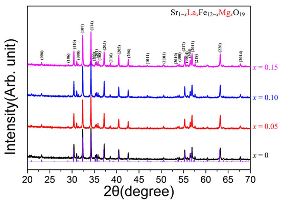
Figure 1.
X-ray diffraction patterns of Sr1−xLaxFe12−xMgxO19 (x = 0, 0.05, 0.1, 0.15) powders after sintering at 1230 °C.
Figure 2a–d show the SEM micrographs of Sr1−xLaxFe12−xMgxO19 (x = 0, 0.05, 0.1, 0.15) samples, illustrating the microstructural evolution with varying La–Mg substitution levels. All samples were sintered at 1230 °C with the addition of 0.5 wt% SiO2 and 1 wt% CaCO3 as sintering aids. The grain size distributions of each sample are presented as histograms in Figure 3a–d. In the case of the unsubstituted SrFe12O19 sample (Figure 2a), the average grain size was 1.45 μm. With La–Mg substitutions, the average grain size slightly increased to about 1.5 μm at x = 0.05, while it was refined to around 1.0 μm at higher substitution levels of x = 0.1 and 0.15.
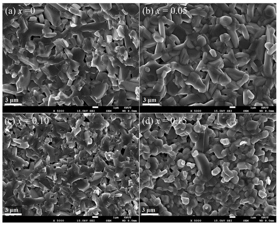
Figure 2.
(a–d) SEM micrographs of sintered Sr1−xLaxFe12−xMgxO19 (x = 0, 0.05, 0.1, 0.15) samples.
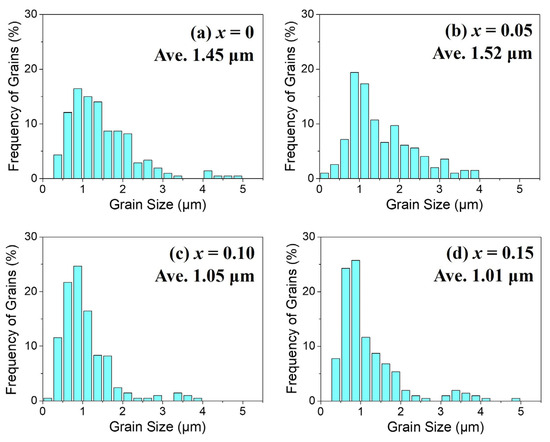
Figure 3.
(a–d) Grain size distribution histograms corresponding to the SEM micrographs of Sr1−xLaxFe12−xMgxO19 (x = 0, 0.05, 0.1, 0.15) samples shown in Figure 2a–d.
Figure 4a shows the M–H curves of Sr1−xLaxFe12−xMgxO19 (x = 0, 0.05, 0.1, 0.15) samples. The specimens used for the VSM measurements were rectangular sintered bodies (~2.0 mm × ~1.5 mm × ~0.8 mm), and the magnetization (M) values represent the magnetic moment measured in emu normalized by the sample mass. In the VSM measurements, attention was focused on the intrinsic property of each cation-substituted sample—specifically, the variation in the MS per unit mass. The compositional dependence of MS and Hc values with increasing substitution level x is shown in Figure 4b, and the numerical values are summarized in Table 1.
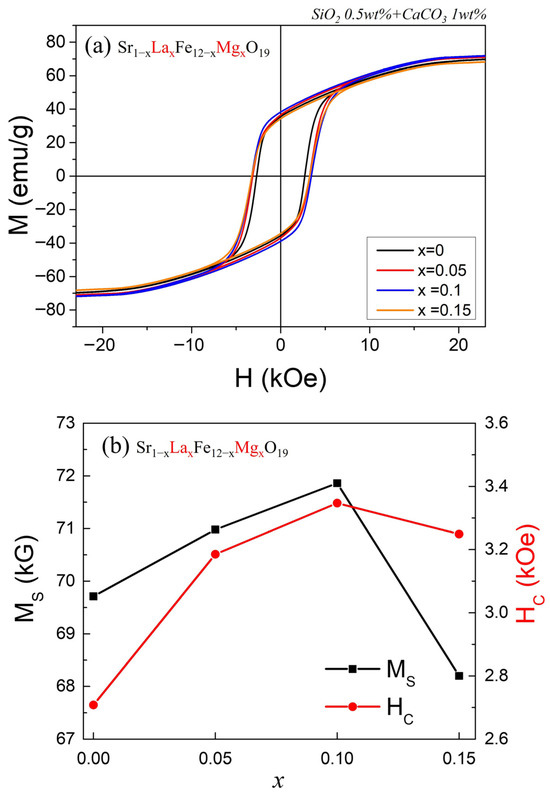
Figure 4.
(a) Magnetic hysteresis curves of the Sr1−xLaxFe12−xMgxO19 (x = 0, 0.05, 0.1, 0.15) samples and (b) plots of MS and HC vs. x.

Table 1.
Sample density, saturation magnetization (MS) and coercivity (HC) measured by VSM and remanent magnetization (4πMr) and coecivity (HC) measured by B-H loop tracer of the Sr1−xLaFe12−xMgxO19 (x = 0, 0.05, 0.1, 0.15) powders after sintering at 1230 °C.
Both MS and HC increased as x increased from 0 to 0.1, but decreased simultaneously at x = 0.15. As confirmed in Figure 1, all four samples consist of a single M-type phase; therefore, the change in MS can be attributed to variations in the net spin moment of Fe3+ ions contributing to MS. Since La3+ substitutes for Sr2+ and Mg2+ substitutes for Fe3+ simultaneously, the valence state of the remaining Fe3+ ions is not expected to change. Under this assumption, the enhanced MS observed at x = 0.1 indicates that the nonmagnetic Mg2+ ions preferentially occupy the down-spin Fe3+ sites in the M-type hexaferrite structure.
Such an increase in MS due to selective cation substitution has also been reported for minor La–Zn and Mn–Zn substitutions in M-type hexaferrites. In the case of La–Zn substitution, the highest MS was obtained at x = 0.3 [13], whereas for Mn–Zn substitution, the maximum MS occurred at x = 0.1 [14]. However, when the substitution level of nonmagnetic ions exceeds a certain limit, MS inevitably decreases, as also observed for the La–Mg system, where MS begins to decrease beyond x = 0.15.
Generally, when MS increases, the HC tends to decrease because of the weakening of the magnetic anisotropy. However, in the La–Mg substituted samples, both MS and HC increased simultaneously from x = 0.05 to x = 0.1, which is a noteworthy result. Since HC is also influenced by extrinsic factors such as the average grain size and its distribution, these effects should be considered together. The HC is known to follow the relationship:
where Dcri is the critical grain size for a single domain [15]. The fact that the x = 0.05 sample exhibited a higher HC value despite having a larger average grain size than the unsubstituted sample suggests that the La–Mg substitution enhanced the intrinsic hard magnetic properties, such as the magnetocrystalline anisotropy constant (Ku), of the M-type hexaferrite. Because HC is proportional to the anisotropy field (Hani), which is related to MS by Hani = 2Ku/MS, a simultaneous increase without decreasing MS implies that the Ku increased with La–Mg substitution, resulting in enhanced Hani and consequently higher HC.
HC = Dcri/D1.08
Figure 5a presents the demagnetization curves of sintered Sr1−xLaxFe12−xMgxO19 (x = 0, 0.05, 0.1, 0.15) samples, measured using a B–H loop tracer. While the M–H curves in Figure 4 were obtained by a VSM using small specimens (~2.0 mm × ~1.5 mm × ~0.8 mm) under vibration, the demagnetization curves in Figure 5 were acquired from disk-shaped samples with a much larger volume (diameter ~24 mm, thickness ~6 mm). In this measurement, a varying magnetic field was applied to the specimen, and the magnetic flux density change was detected through a J-coil. Thus, the results in Figure 5 more closely represent the actual magnetic performance of isotropic sintered magnets. Figure 5b show the variations in remanent flux density (4πMr) and HC as a function of the substitution level x. The trend of 4πMr with increasing x is consistent with that of the VSM-derived results in Figure 4b. However, while MS obtained from the VSM represents an intrinsic magnetic property (magnetization per unit mass), 4πMr is influenced by extrinsic factors such as sample density and crystallographic alignment.
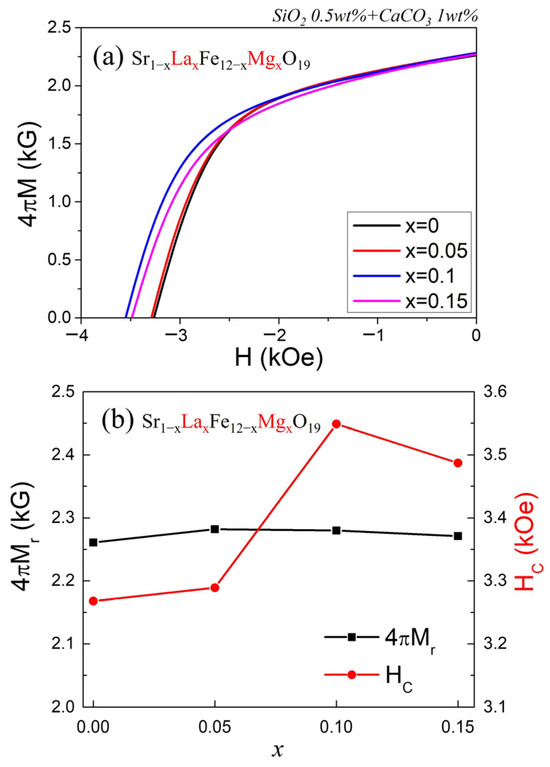
Figure 5.
(a) Demagnetization curves (4πM vs. H) of the sintered Sr1−xLaxFe12−xMgxO19 (x = 0, 0.05, 0.1, 0.15) samples and (b) plots of 4πMr and HC vs. x.
Practically, the 4πMr value (in units of Gauss) obtained from the B–H loop tracer can be related to the MS (in emu/g) measured by the VSM through the following equation [20]:
4πMr = 4π∙MS∙ρ∙S∙(1 − fi)
Here, ρ represents the density of the sintered sample (in g/cm3), and S denotes the grain orientation factor, which takes a value of 1 when all grains are perfectly aligned along the c-axis and 0.5 when they are completely randomly oriented. fi is the volumetric fraction of nonmagnetic impurities. Since the present samples are randomly oriented isotropic magnets, S value is expected to be close to 0.5 [2]. For the La–Mg substituted samples, in which no secondary phase was detected, the fi value can be regarded as zero (fi ≈ 0).
The dependence of HC on x also follows a similar trend to that shown in Figure 4b,c, although the absolute values differ slightly. Because the B–H loop tracer data are obtained from specimens with a volume roughly 1000 times larger than those used in the VSM, they are considered more representative of the macroscopic magnetic behavior and compositional dependence. The apparent sintered density of the disk samples, along with the 4πMr and HC values obtained from the B–H loop tracer measurements, are also presented in Table 1. Considering all results, the Sr0.9La0.1Fe11.9Mg0.1O19 sample (x = 0.1) exhibited the most superior hard magnetic properties, with the highest MS of 71.9 emu/g, a remanent flux density of 2280 G, and a HC of 3549 Oe.
Finally, to further optimize the hard magnetic properties, additional B–H loop tracer measurements were performed on Sr0.9La0.1Fe11.9Mg0.1O19 samples fabricated using various sintering additives, as shown in Figure 6a. Among the sintering additives, SiO2 and Al2O3 are known to effectively suppress grain growth, while CaCO3, CaO, SrCO3, Bi2O3, and CuO promote densification and grain coarsening [21,22,23,24]. Figure 6a presents the demagnetization curves for samples prepared with six different combinations of sintering aids. Curve A represents the sample sintered with the original additives, 0.5 wt% SiO2 and 1.0 wt% CaCO3. When 0.5 wt% SiO2 and 0.5 wt% SrCO3 were additionally introduced, as shown in curve B, both 4πMr and HC improved simultaneously. In curve C, 4πMr slightly decreased compared with B, while HC increased significantly (when 1 wt% of CaCO3 was replaced by 0.5 wt% of CaO, and the SiO2 and SrCO3 contents were adjusted to 0.8 wt% and 0.7 wt%, respectively). For the samples containing Al2O3 (curves D and E), high HC values were obtained; however, this was accompanied by a significant reduction in 4πMr. Among them, the sample sintered with 0.8 wt% SiO2, 0.3 wt% SrCO3, 0.3 wt% Al2O3, and 0.5 wt% CaO exhibited the highest HC = 4811 Oe (curve E). On the other hand, when Bi2O3 or CuO was used instead of SrCO3, the sintered density increased most significantly, but HC decreased considerably.
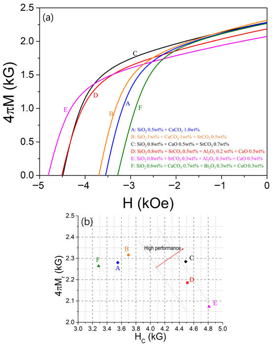
Figure 6.
(a) Demagnetization cures of Sr0.9La0.1Fe11.9Mg0.1O19 samples sintered with various sintering additives, and (b) plot of remanent magnetization (4πMr) vs. coercivity (HC) of the samples.
Figure 6b summarizes these results by plotting 4πMr versus HC. Since these two parameters generally exhibit a trade-off relationship, samples located toward the upper-right region of the graph are considered to have superior hard magnetic performance. Accordingly, the sample corresponding to curve C, prepared with 0.8 wt% SiO2, 0.5 wt% CaO, and 0.7 wt% SrCO3, demonstrated the best isotropic magnetic properties, achieving HC = 4489 Oe and 4πMr = 2285 G. Furthermore, if this composition were subjected to magnetic field alignment before sintering—thereby increasing the grain orientation factor S in Equation (2) to approximately 0.95—and further improving the sintered density, it is expected that an anisotropic magnet with 4πMr ≈ 4500 G could be fabricated, albeit with a slight decrease in HC. The values of 4πMr and HC are also presented in Table 2. These results demonstrate a remarkable enhancement in magnetic properties achieved without the use of Co, which is typically considered an essential element for high-performance ferrite fabrication, indicating the great potential of this approach.
Table 2.
Sintering density, remanent magnetization (4πMr), and coercivity (HC) of M-type hexaferrite samples according to sintering additives.
4. Summary
La–Mg co-substituted M-type Sr-hexaferrites, Sr1−xLaxFe12−xMgxO19 (x = 0, 0.05, 0.1, 0.15) were successfully synthesized using a conventional solid-state reaction method, and their structural and magnetic properties were systematically investigated. XRD analysis confirmed that La–Mg substitution yielded single-phase M-type hexaferrites up to x = 0.15. Among all compositions, the Sr0.9La0.1Fe11.9Mg0.1O19 sample (x = 0.1) exhibited the optimal hard magnetic properties, achieving a high MS of 71.9 emu/g, a remanent flux density (4πMr) of 2280 G, and a HC of 3549 Oe. The observed enhancement in both MS and HC can be attributed to the synergistic effect of La3+ and Mg2+ substitution, which increased MS and KU while refining grain morphology. Additional improvements were achieved by employing sintering additives, which played a crucial role in controlling densification and grain growth. In particular, the combination of 0.8 wt% SiO2, 0.5 wt% CaO, and 0.7 wt% SrCO3 resulted in the best hard magnetic properties, realizing an HC of 4489 Oe and a 4πMr of 2285 G. These findings highlight that the co-substitution of rare-earth and Mg ions, combined with precise control of sintering additives and microstructure, can effectively enhance hard magnetic performance without the use of cobalt. This approach provides a promising and environmentally friendly route for developing next-generation high-performance ferrite magnets for advanced motor, energy, and electronic applications.
Author Contributions
Conceptualization, Y.-M.K.; methodology, J.-J.K.; software, J.-J.K.; validation, Y.-M.K. and J.-J.K.; formal analysis, Y.-M.K. and J.-J.K.; investigation, Y.-M.K. and J.-J.K.; writing—original draft preparation, Y.-M.K.; writing—review and editing, Y.-M.K.; visualization, Y.-M.K. and J.-J.K.; supervision, Y.-M.K.; project administration, Y.-M.K.; funding acquisition, Y.-M.K. All authors have read and agreed to the published version of the manuscript.
Funding
This research was supported by the Regional Innovation System & Education (RISE) program through the (Chungbuk Regional Innovation System & Education Center), funded by the Ministry of Education (MOE) and the (Chungcheongbuk-do), Republic of Korea (2025-RISE-11-004-03).
Institutional Review Board Statement
Not applicable.
Informed Consent Statement
Not applicable.
Data Availability Statement
The data presented in this study are available on request from the corresponding author. The data are not publicly available due to privacy.
Conflicts of Interest
The authors declare no conflicts of interest.
References
- Smit, J.; Wijn, H.P.J. Ferrites: Physical Properties of Ferromagnetic Oxides in Relation to Their Technical Applications; Philips Technical Library: Eindhoven, The Netherlands, 1959. [Google Scholar]
- Pullar, R.C. Hexagonal ferrites: A review of the synthesis, properties and applications of hexaferrite ceramics. Prog. Mater. Sci. 2012, 57, 1191–1334. [Google Scholar] [CrossRef]
- de Julián Fernández, C.; Sangregorio, C.; de la Figuera, J.; Belec, B.; Makovec, D.; Quesada, A. Progress and prospects of hard hexaferrites for permanent magnet applications. J. Phys. D Appl. Phys. 2021, 54, 153001. [Google Scholar] [CrossRef]
- Sudakar, C.; Subbanna, G.N.; Kutty, T.R.N. Wet chemical synthesis of multicomponent hexaferrites by gel-to-crystallite conversion and their magnetic properties. J. Magn. Magn. Mater. 2003, 263, 253–268. [Google Scholar] [CrossRef]
- Grossinger, R.; Kupferling, M.; Blanco, J.C.T.; Wiesinger, G.; Muller, M.; Hilscher, G.; Pieper, M.W.; Wang, J.F.; Harris, I. Rare earth substitutions in M-type ferrites. IEEE Trans. Magn. 2003, 39, 2911–2913. [Google Scholar] [CrossRef]
- Lobo-Guerrero, A.; Salazar-Muñoz, V.E.; Aguilera Del Toro, R.H.; Hernández-Vázquez, E.E. M-type hexaferrites: A review of the impact of rare earth substitution on magnetic properties. J. Magn. Magn. Mater. 2025, 627, 173132. [Google Scholar] [CrossRef]
- Todkar, G.B.; Kunale, R.A.; Kamble, R.N.; Batoo, K.M.; Ijaz, M.F.; Imran, A.; Hadi, M.; Raslan, E.H.; Shirsath, S.E.; Kadam, R.H. Ce–Dy substituted barium hexaferrite nanoparticles with large coercivity for permanent magnet and microwave absorber application. J. Phys. D Appl. Phys. 2021, 54, 294001. [Google Scholar] [CrossRef]
- Ueda, H.; Tanioku, Y.; Michioka, C.; Yoshimura, K. Magnetocrystalline anisotropy of La- and Co-substituted M-type strontium ferrites: Role of Co2+ and Fe2+. Phys. Rev. B 2017, 95, 224421. [Google Scholar] [CrossRef]
- Cao, C.; Li, X.; Luo, B.; Li, Y.; Zhang, A.; Xia, A. Ce-substituted M-type SrFe12O19 ferrites: Phase formation and magnetic properties. J. Supercond. Nov. Magn. 2018, 31, 1247–1251. [Google Scholar] [CrossRef]
- Huang, K.; Yu, J.; Zhang, L.; Xu, J.; Yang, Z.; Liu, C.; Wang, W.; Kan, X. Structural and magnetic properties of Gd–Zn substituted M-type Ba–Sr hexaferrites by sol–gel auto-combustion method. J. Alloys Compd. 2019, 803, 971–980. [Google Scholar] [CrossRef]
- Islam, M.R.; Khan, M.K.R.; Hossain, M.S.; Rahman, M.M.; Haque, M.M.; Aliuzzaman, M.; Alam, M.K.; Sarker, M.S.I. Structural, thermodynamic, and magnetic properties of SrFe12O19 hexaferrite modified by co-substitution of Cu and Gd. RSC Adv. 2024, 14, 7314–7328. [Google Scholar] [CrossRef]
- Yasmin, N.; Mirza, M.; Muhammad, S.; Zahid, M.; Ahmad, M.; Awan, M.S.; Muhammad, A. Influence of samarium substitution on the structural and magnetic properties of M-type hexagonal ferrites. J. Magn. Magn. Mater. 2018, 446, 276–281. [Google Scholar] [CrossRef]
- Bai, J.; Liu, X.; Xie, T.; Wei, F.; Yang, Z. The effects of La–Zn substitution on the magnetic properties of Sr-magnetoplumbite ferrite nanoparticles. Mater. Sci. Eng. B 2000, 68, 182–185. [Google Scholar] [CrossRef]
- Kang, Y.-M.; Kwon, Y.-H.; Kim, M.-H.; Lee, D.-Y. Enhancement of magnetic properties in Mn–Zn substituted M-type Sr-hexaferrites. J. Magn. Magn. Mater. 2015, 382, 10–14. [Google Scholar] [CrossRef]
- Nishio, H.; Minachi, Y.; Yamamoto, H. Effect of factors on coercivity in Sr–La–Co sintered ferrite magnets. IEEE Trans. Magn. 2009, 45, 5281–5288. [Google Scholar] [CrossRef]
- Kang, Y.-M.; Moon, K.-S. Magnetic properties of Ce–Mn substituted M-type Sr-hexaferrites. Ceram. Int. 2015, 41, 12828–12834. [Google Scholar] [CrossRef]
- Manglam, M.K.; Shukla, A.; Mallick, J.; Yadav, M.K.; Kumari, S.; Zope, M.; Kar, M. Enhancement of coercivity of M-type barium hexaferrite by Ho doping. Mater. Today Proc. 2022, 59, 149–152. [Google Scholar] [CrossRef]
- Shirsath, S.E.; Kadam, R.H.; Batoo, K.M.; Wang, D.; Li, S. Co–Al-substituted strontium hexaferrite for rare-earth-free permanent magnet and microwave absorber application. J. Phys. D Appl. Phys. 2021, 54, 024001. [Google Scholar] [CrossRef]
- Han, G.; Sui, R.; Yu, Y.; Wang, L.; Li, M.; Li, J.; Liu, H.; Yang, W. Structure and magnetic properties of the porous Al-substituted barium hexaferrites. J. Magn. Magn. Mater. 2021, 528, 167824. [Google Scholar] [CrossRef]
- Lim, J.-P.; Kang, M.-G.; Kang, Y.-M. Development of multi-cation-doped M-type hexaferrite permanent magnets. Appl. Sci. 2023, 13, 295. [Google Scholar] [CrossRef]
- Guzmán-Mínguez, J.C.; Vicente-Arche, L.M.; Granados-Miralles, C.; Fernández, J.F.; Quesada, A. Improvement of the magnetic properties of SrFe12O19 ceramics by tailored sintering with SiO2 addition. J. Alloys Compd. 2021, 860, 157890. [Google Scholar] [CrossRef]
- Huang, C.-C.; Jiang, A.-H.; Hung, Y.-H.; Liou, C.-H.; Wang, Y.-C.; Lee, C.-P.; Hung, T.-Y.; Shaw, C.-C.; Kuo, M.-F.; Cheng, C.-H. Influence of CaCO3 and SiO2 additives on magnetic properties of M-type Sr ferrites. J. Magn. Magn. Mater. 2018, 451, 288–294. [Google Scholar] [CrossRef]
- Li, J.; Zhang, H.W.; Li, Y.X.; Su, H.; Ma, Y.B. Influence of Bi2O3 on the structure and magnetic properties of barium ferrite powders. Adv. Mater. Res. 2012, 499, 31–34. [Google Scholar] [CrossRef]
- Matran, W.M.; Mustapha, M.; Nor, M.F. The influences of additives in M−type (Ba and Sr) hexaferrites’ microstructure, sintering and magnetic properties: A review. Mater. Today Proc. 2024, 96, 78–83. [Google Scholar] [CrossRef]


Disclaimer/Publisher’s Note: The statements, opinions and data contained in all publications are solely those of the individual author(s) and contributor(s) and not of MDPI and/or the editor(s). MDPI and/or the editor(s) disclaim responsibility for any injury to people or property resulting from any ideas, methods, instructions or products referred to in the content. |
© 2025 by the authors. Licensee MDPI, Basel, Switzerland. This article is an open access article distributed under the terms and conditions of the Creative Commons Attribution (CC BY) license (https://creativecommons.org/licenses/by/4.0/).