A Loss Model System for Two-Dimensional Compressor Cascades of Modern Controlled Diffusion Airfoils
Abstract
1. Introduction
2. Numerical Simulation Database for 2D CDA Cascades
2.1. Parameter Space
2.2. Numerical Methods
- (1)
- The inlet total pressure and the inlet total temperature were equal to the experimentally measured values.
- (2)
- The inlet flow angle varied stepwise from near-stall to near-choke conditions, with a step size ranging from 0.1° to 1°. In addition, for cascades that had experimental data, the measured inlet flow angles were also included in the numerical calculation to enable direct comparison between numerical and experimental results.
- (3)
- By adjusting the outlet static pressure, the inlet Mach number in the numerical calculation achieved the design value which had already been determined at the cascade design stage. The inlet Mach number in the experiments was also set to this design value by adjusting the wind tunnel speed.
3. Development of the Loss Model System for 2D CDA Cascades
3.1. Model System Structure
3.2. Reference Profile Loss Model
3.2.1. Baseline Model Formulation of Reference Profile Loss Model
3.2.2. Error Attribution Analysis for Baseline Model of Reference Profile Loss Model
3.2.3. Optimization and Validation of Reference Profile Loss Model
3.3. Reference Shock Loss Model
3.3.1. Baseline Model Formulation of Reference Shock Loss Model
3.3.2. Optimization and Validation of Reference Shock Loss Model
3.4. Throat Choking and Unique Incidence Angle Models
3.5. Reference Incidence Angle Model
3.6. Non-Reference Loss Model
4. Validation of the Loss Model System for 2D CDA Cascades
4.1. Validation on the Training Set
4.2. Validation on the Test Set
4.3. Validation Against Experimental Data
5. Conclusions
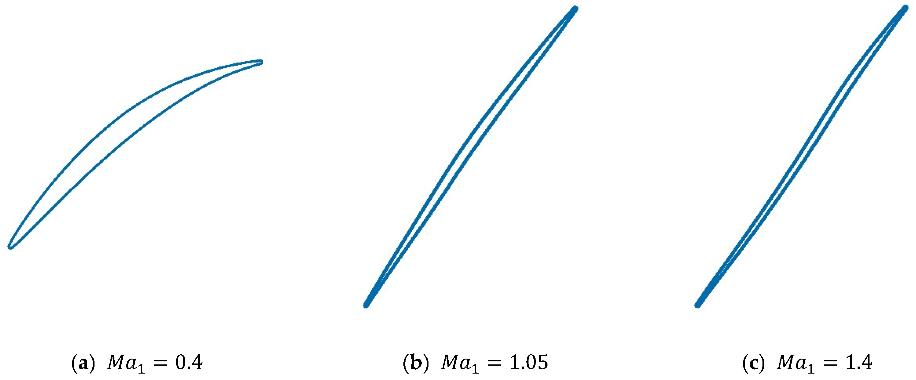
- A wide-range numerical simulation database for 2D CDA cascades was constructed. The database contains 920 cascade configurations and 9426 operating points, covering flow states from subsonic to supersonic (inlet Mach number 0.4–1.4), the full operating range from stall to choke (incidence angle −23° to 19°), and various profile designs, from low to high loading, front-loaded to aft-loaded, and so on. This provides a solid data foundation for the development and validation of the new model system.
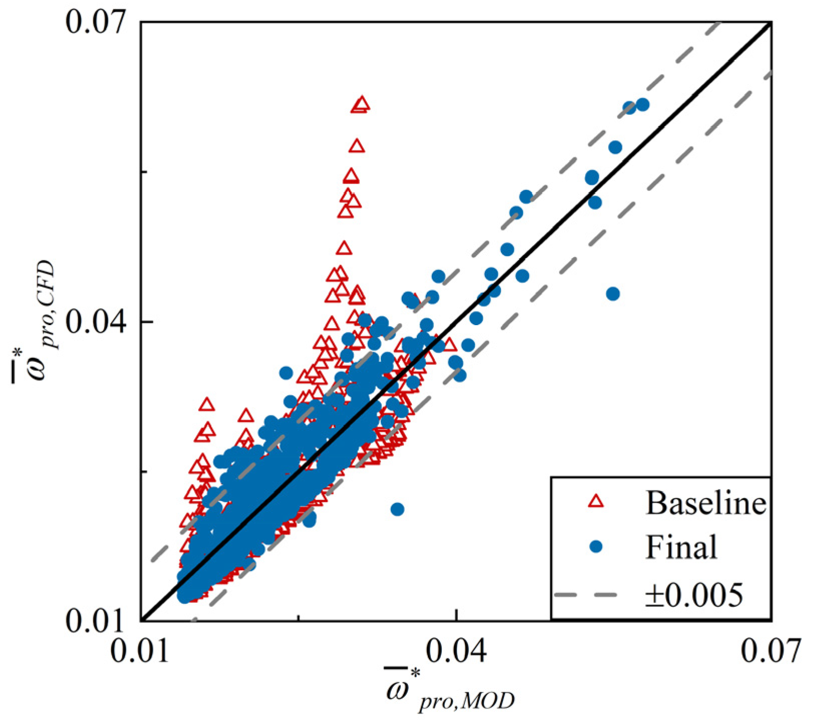
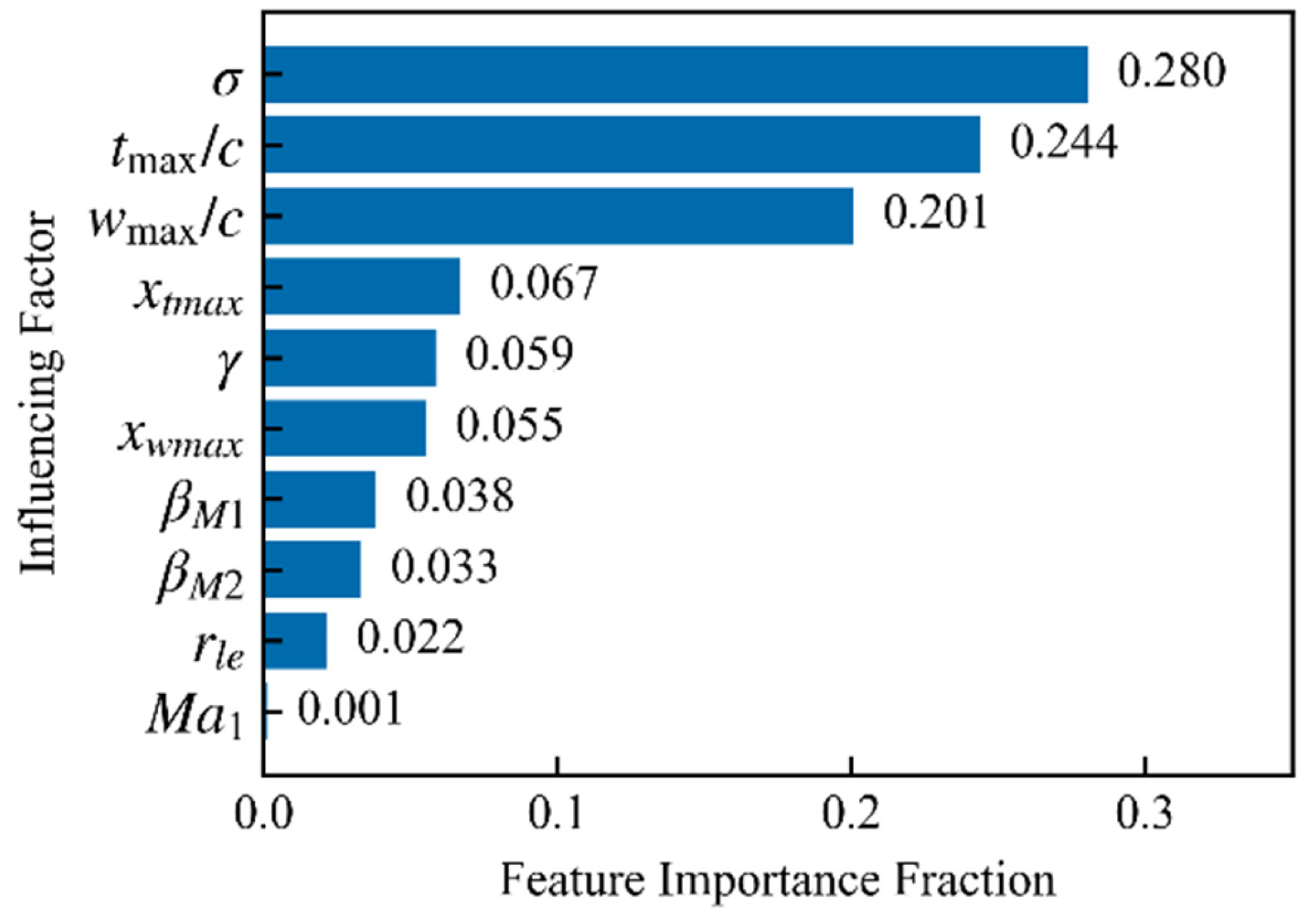
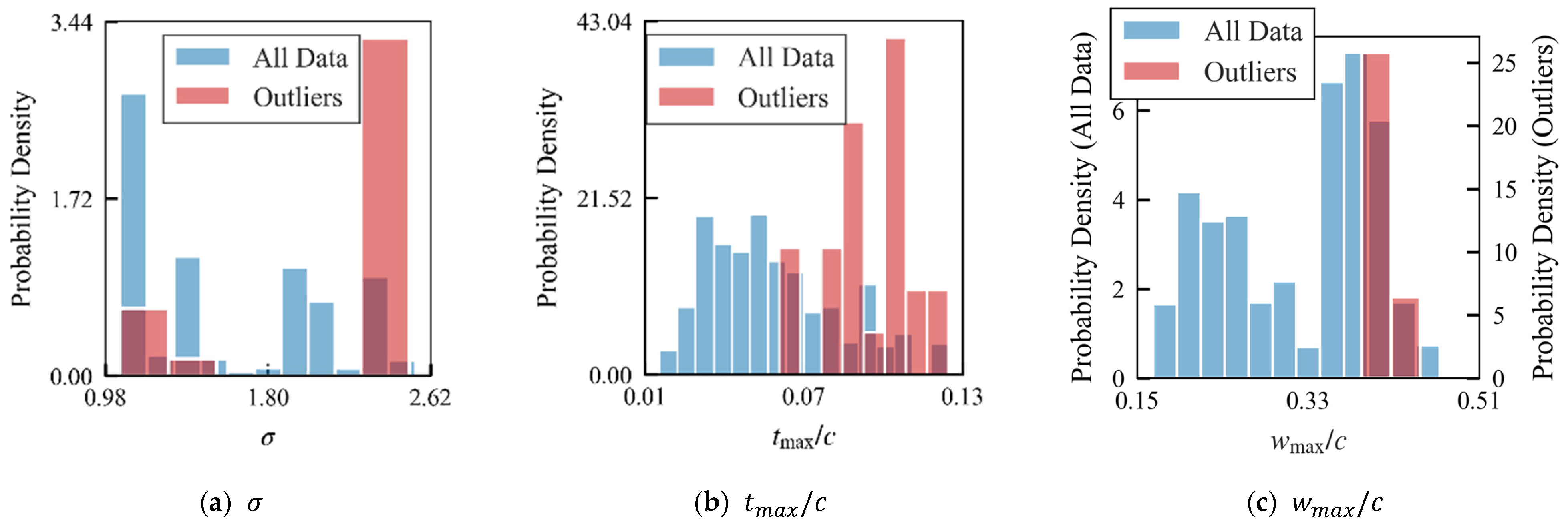
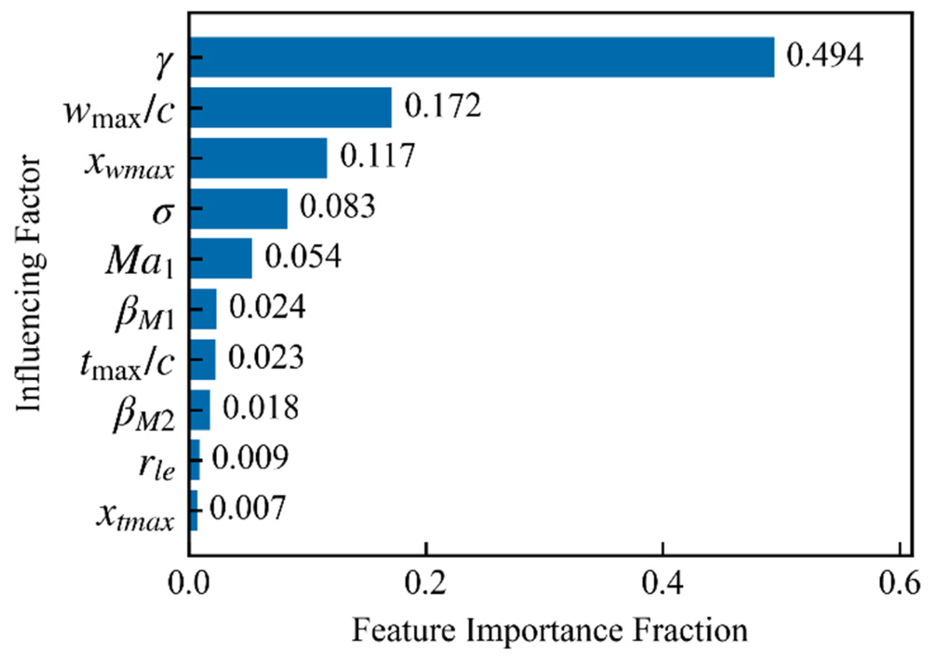
- New models were obtained by applying data-driven techniques to optimize traditional models with solid physical foundations. The study found that the theoretical core of the traditional models remains applicable to CDA profiles, but their empirical correlations are generally inadequate. The Gradient Boosting Machine method was introduced to perform quantitative attribution analysis on the model errors, identifying critical influencing factors for targeted optimization. Employing this method, significant accuracy improvement was achieved merely through simple modifications to the formulas.
- Important mechanisms influencing the modeling of reference profile loss for 2D CDA cascades were revealed. For the majority of CDA cascades in the database, a distinct linear correlation exists between the equivalent diffusion factor and the critical wake term in the reference profile loss model. Additionally, variations in the axial load distribution, as well as blade surface boundary layer separation and friction effects, have a non-negligible influence on the loss prediction for part of the profiles located at the edges of the parameter space.
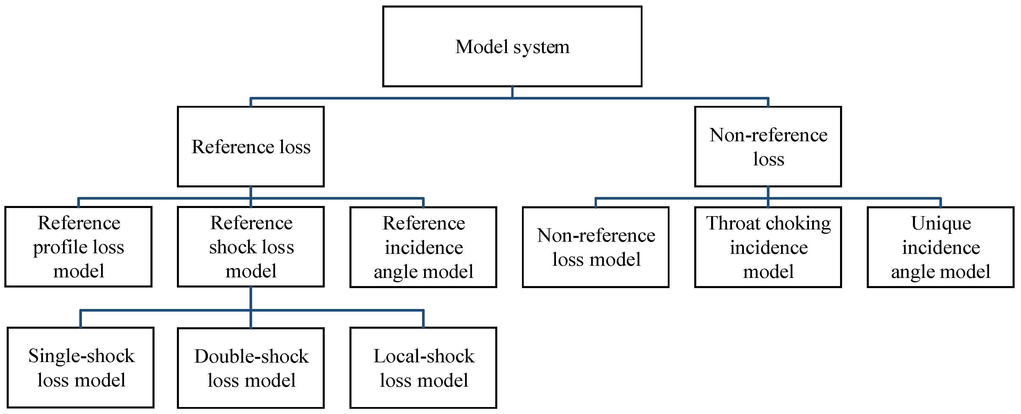
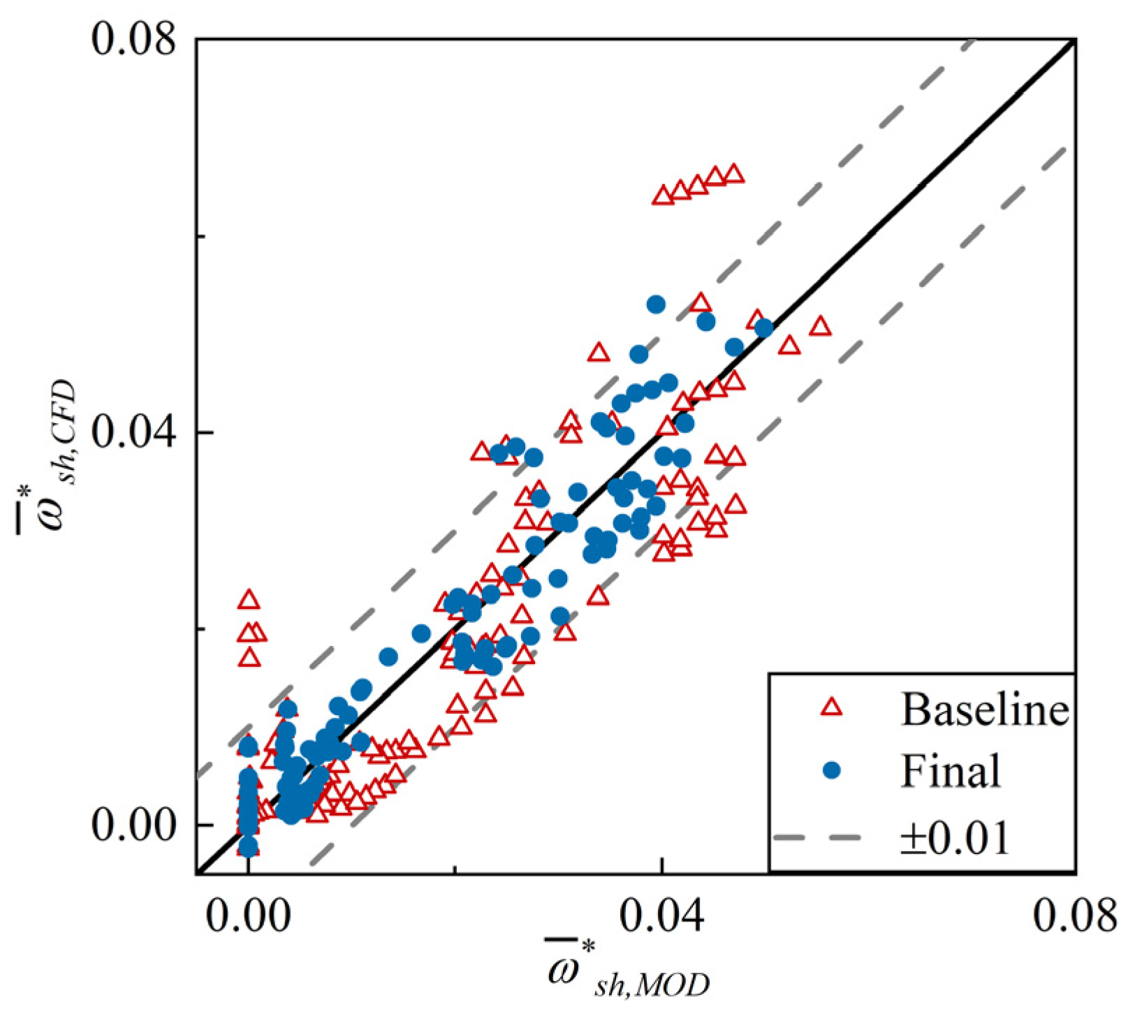
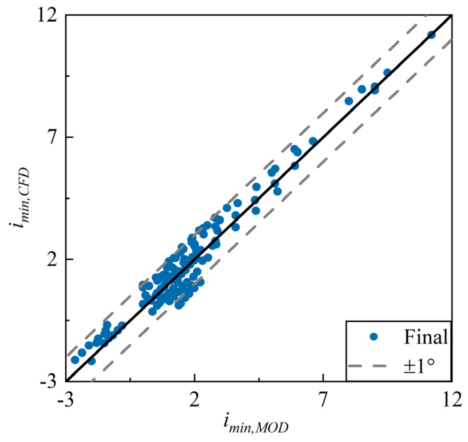
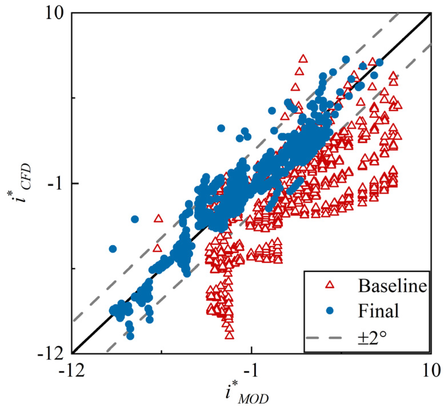
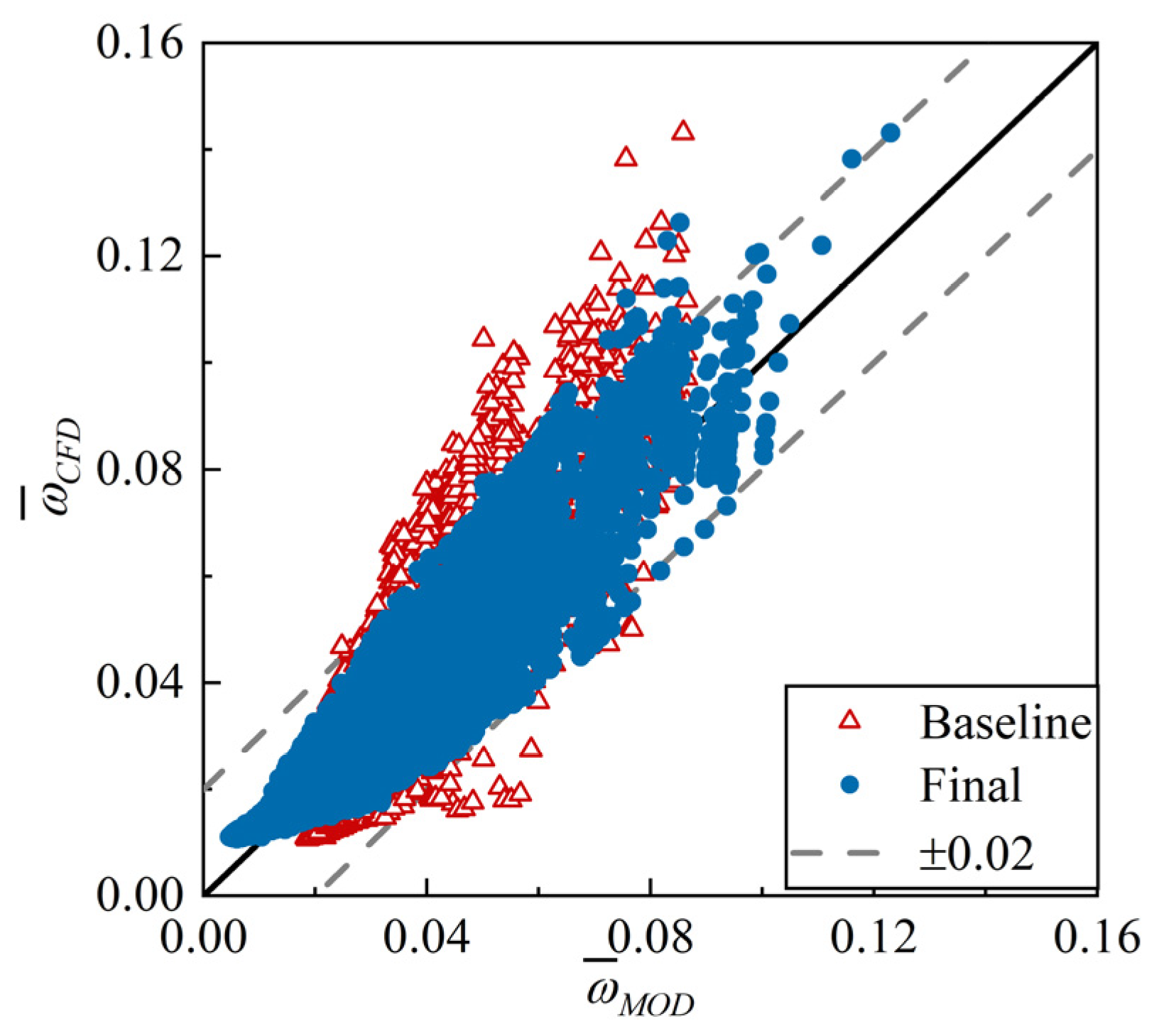
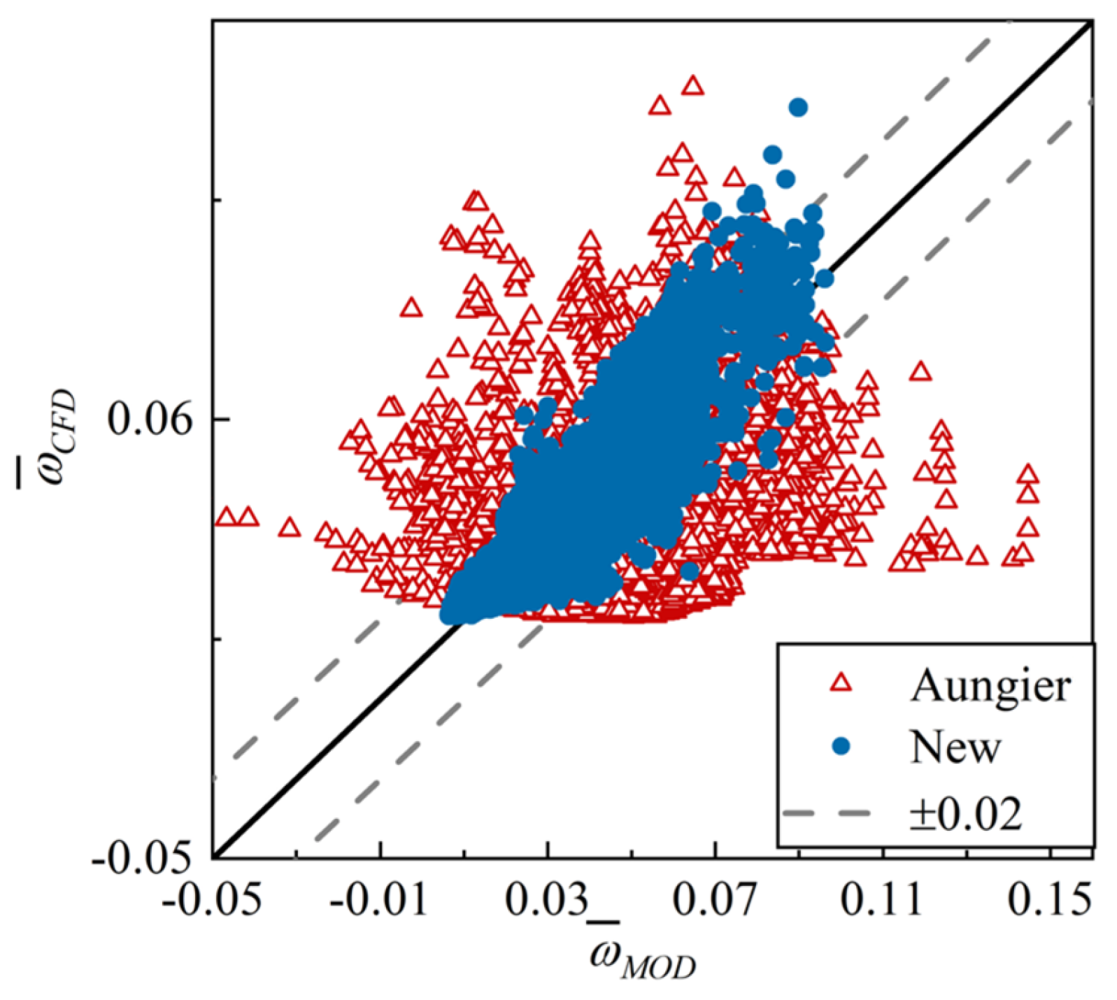
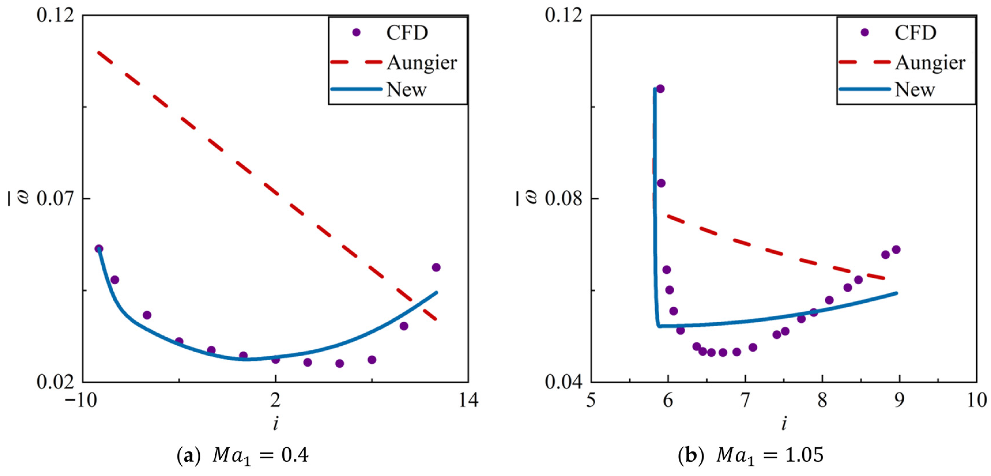
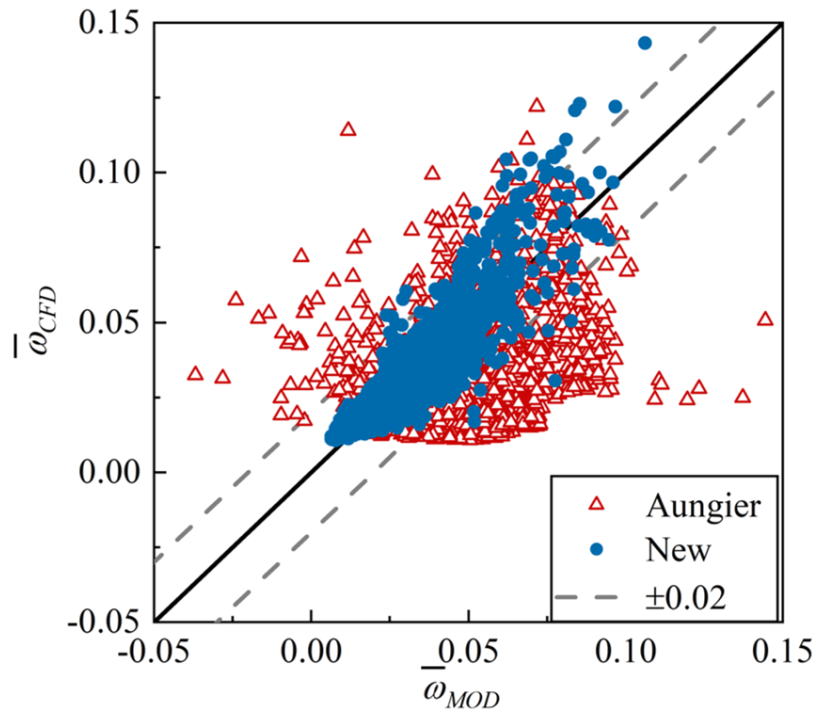
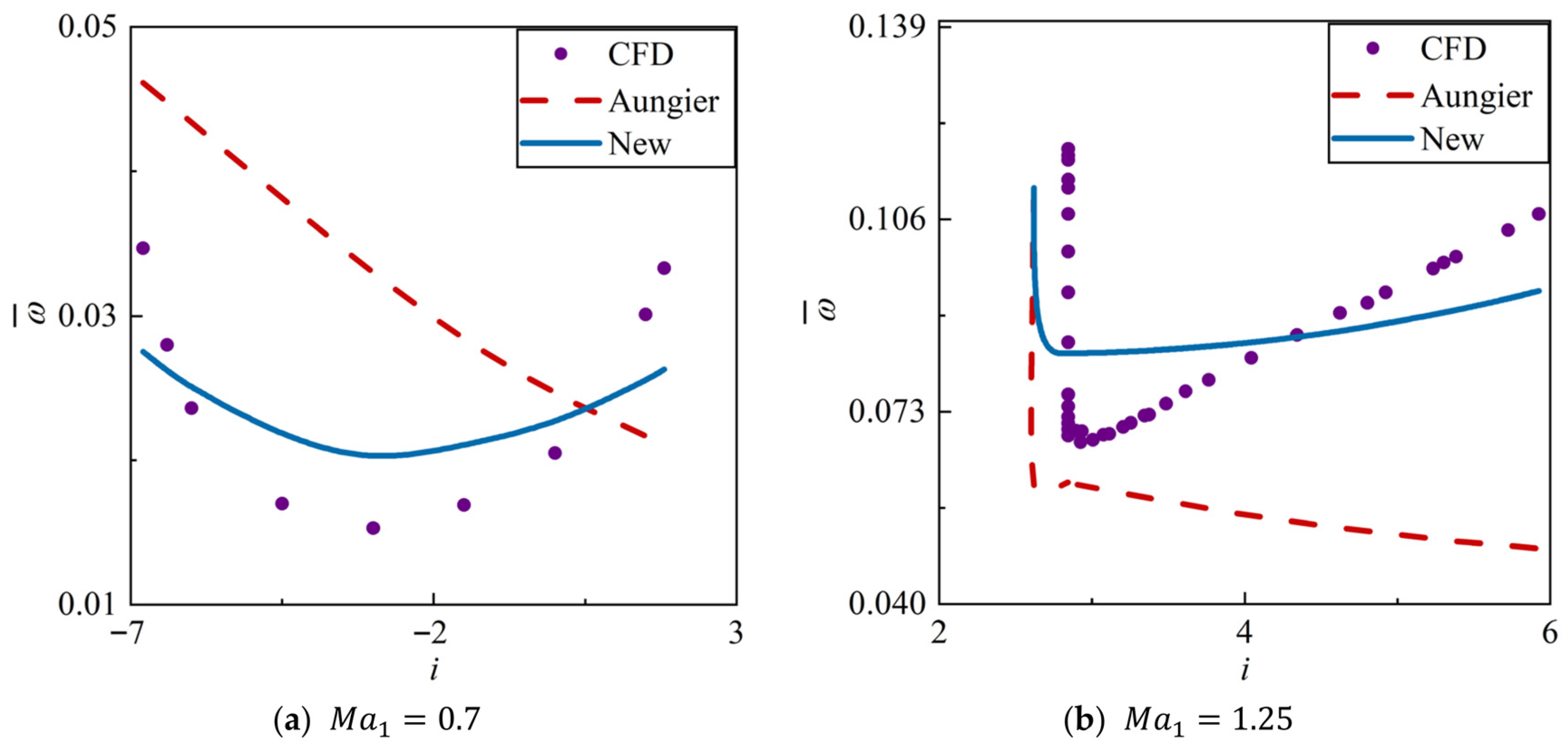
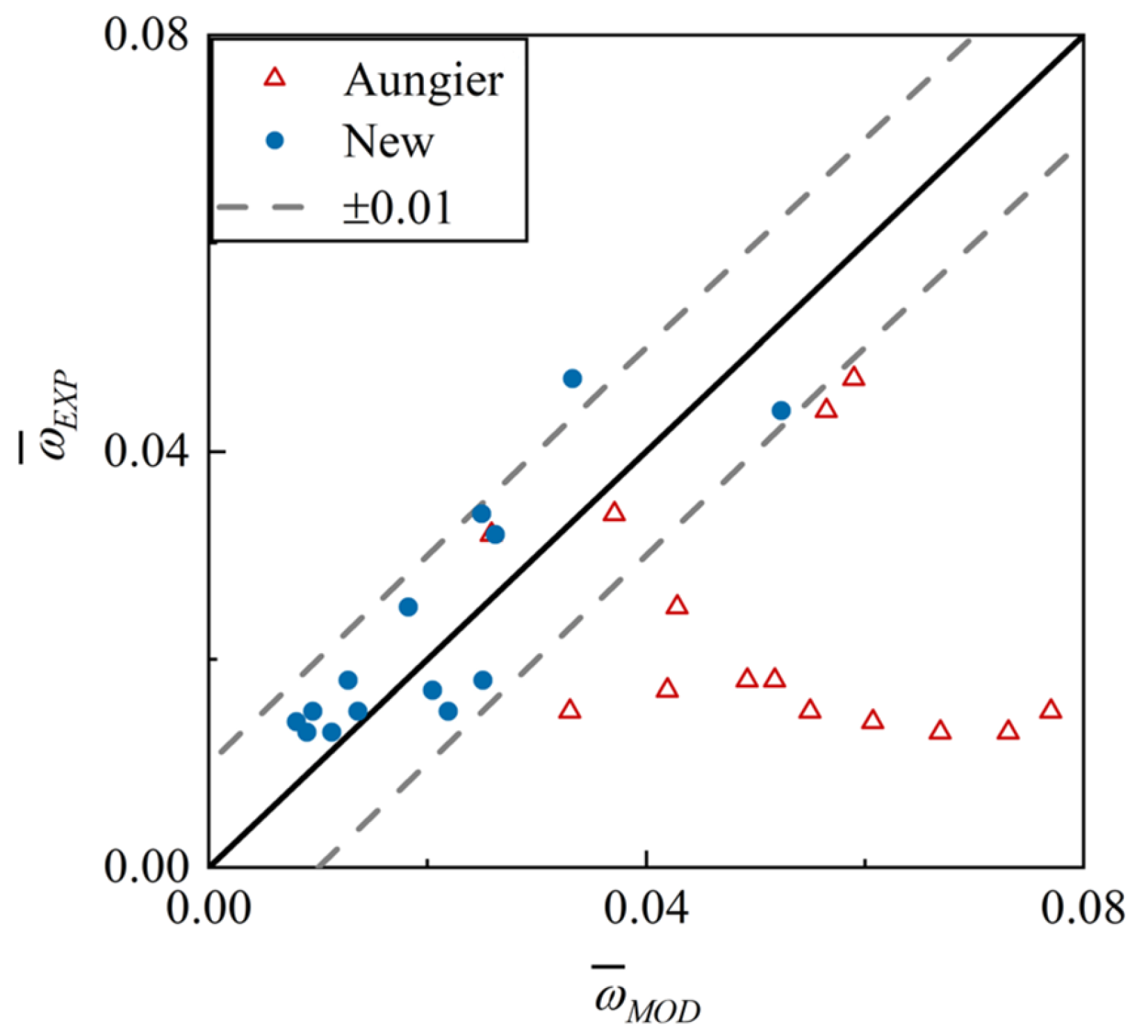
- An all-operation loss model system for 2D CDA cascades was developed. The system is composed of a series of explicit expressions with clear physical significance. Across all the data, about 95% of the absolute prediction errors are less than 0.018. The new model reduces the RMSE by over 77% compared to the classical Aungier model system [8], demonstrating its superior accuracy.
Author Contributions
Funding
Institutional Review Board Statement
Informed Consent Statement
Data Availability Statement
Conflicts of Interest
Nomenclature
| Symbols | |
| Chord length | |
| Diffusion factor | |
| Equivalent diffusion factor | |
| Blade wake term in the reference profile loss model | |
| Blade wake shape factor | |
| Incidence angle | |
| Reference incidence angle of NACA65 profile with 0° camber angle and 10% maximum relative thickness | |
| Minimum incidence angle | |
| Throat choking incidence angle | |
| Unique incidence angle | |
| Correction factor for maximum relative thickness | |
| Weighting factor for reference shock loss | |
| Mach number | |
| Mach number after isentropic expansion to the shock wave front along the suction surface | |
| Peak Mach number on the suction surface | |
| Mach number at the shock wave front | |
| Correction factor for camber angle | |
| Leading edge radius | |
| Maximum thickness | |
| Maximum deflection | |
| Chordwise position of maximum thickness | |
| Chordwise position of maximum deflection | |
| Flow angle | |
| Metal angle | |
| Stagger angle | |
| Camber angle | |
| Blade wake momentum thickness | |
| Solidity | |
| Total pressure loss | |
| Profile loss | |
| Shock loss | |
| Double-wave shock loss | |
| Local shock loss | |
| Single-wave shock loss | |
| Model prediction error | |
| Subscripts | |
| 1 | Inlet |
| 2 | Outlet |
| Parameter at the design point | |
| CFD | Numerical result |
| EXP | Experimental result |
| MOD | Model prediction result |
| Superscripts | |
| * | Parameter at the reference point |
References
- Senior, A.C.; Miller, R. Improving Compressor Preliminary Design with Physically Decomposed Loss Models. J. Turbomach. 2026, 148, 021007. [Google Scholar] [CrossRef]
- Guo, Z. The Study of Transition on Controlled Diffusion Airfoils Using Large Simulations; Shanghai Jiao Tong University: Shanghai, China, 2020. [Google Scholar]
- Hobbs, D.; Weingold, H. Development of controlled diffusion airfoils for multistage compressor application. J. Eng. Gas Turbines Power 1984, 106, 271–278. [Google Scholar] [CrossRef]
- Rechter, H.; Steinert, W.; Lehmann, K. Comparison of controlled diffusion airfoils with conventional NACA 65 airfoils developed for stator blade application in a multistage axial compressor. J. Eng. Gas Turbines Power 1985, 107, 494–498. [Google Scholar] [CrossRef]
- Behlke, R. The development of a second generation of controlled diffusion airfoils for multistage compressors. J. Turbomach. 1986, 108, 32–40. [Google Scholar] [CrossRef]
- Lieblein, S. Loss and stall analysis of compressor cascades. J. Basic Eng. 1959, 81, 387–397. [Google Scholar] [CrossRef]
- Koch, C.C.; Smith, L.H. Loss sources and magnitudes in axial-flow compressors. J. Eng. Gas Turbine. Power 1976, 98, 411–424. [Google Scholar] [CrossRef]
- Aungier, R.H. Axial-Flow Compressors: A Strategy for Aerodynamic Design and Analysis; American Society of Mechanical Engineers: New York, NY, USA, 2003. [Google Scholar]
- Miller, G.R.; Lewis, G.W., Jr.; Hartmann, M.J. Shock losses in transonic compressor blade rows. J. Eng. Power. 1961, 83, 235–241. [Google Scholar] [CrossRef]
- Boyer, K.M.; O’Brien, W.F. An improved Streamline Curvature Approach for Off-Design Analysis of Transonic Axial Compression Systems. J. Turbomach. 2003, 125, 475–481. [Google Scholar] [CrossRef]
- Wright, P.I.; Miller, D.C. Improved compressor performance prediction model. In Proceedings of the European Conference on Turbomachinery, London, UK, 19–20 March 1991; pp. 69–82. [Google Scholar]
- Sun, X.; Yang, S.; Zhao, Q. Shock loss model and blade profile optimization design of a supersonic cascade. Proc. Inst. Mech. Eng. Part G J. Aerosp. Eng. 2015, 229, 1325–1329. [Google Scholar] [CrossRef]
- Banjac, M.; Savanovic, T.; Petkovic, D.; Petrovic, M.V. A comprehensive analytical shock loss model for axial compressor cascades. J. Turbomach. 2022, 144, 091003. [Google Scholar] [CrossRef]
- Hearsey, R.M. Program HT0300 NASA 1994 Version; The Boeing Company: Seattle, WA, USA, 1994. [Google Scholar]
- Tao, H.Q.; Xu, N.; Li, R.Z.; Jiang, B. Research on Loss and Deviation Angle Model based on Multivariate Nonlinear Regression. Therm. Energy Power Eng. 2022, 37, 38–46. [Google Scholar]
- Tao, C.; Du, X.; Ding, J.; Luo, Y.; Wang, Z. Maximum thickness location selection of high subsonic axial compressor airfoils and its effect on aerodynamic performance. Front. Energy Res. 2021, 9, 791542. [Google Scholar] [CrossRef]
- Fei, T. Investigation on through-flow analysis framework and empirical model improvement of high-load compressors. Ph.D. Thesis, Beijing Institute of Technology, Beijing, China, 2020. [Google Scholar]
- Yue, Z.; Zhou, C.; Jin, D.; Gui, X. A spanwise loss model for axial compressor stator based on machine learning. Chin. J. Aeronaut. 2022, 35, 74–84. [Google Scholar] [CrossRef]
- Shi, H. Study on Design Method of Super/Transonic Compressor Airfoil and Application; Beihang University: Beijing, China, 2019. [Google Scholar]
- Ning, F.F. Numerical Simulation of Internal Flows in Transonic Compressors with Actual Geometric Fidelity; Beihang University: Beijing, China, 2002. [Google Scholar]
- Creveling, H.F.; Carmody, R.H. Axial Flow Compressor Computer Program for Calculating off Design Performance (Program IV); NASA-CR-72427; NASA: Washington, DC, USA, 1968. [Google Scholar]
- Zhao, Y.; Hu, J. Analysis of the influence of inlet flow distortion on the off-design performance of fan/booster. J. Aerosp. Power 2007, 22, 1087–1092. [Google Scholar] [CrossRef]
- Levine, P. Two-dimensional inflow conditions for a supersonic compressor with curved blades. J. Appl. Mech. 1957, 24, 165–169. [Google Scholar] [CrossRef]
- Lieblein, S. Incidence and deviation-angle correlations for compressor cascades. J. Basic Eng. 1960, 82, 575–584. [Google Scholar] [CrossRef]


| Parameter | Range |
|---|---|
| /(°) | −23–19 |
| 0.4–1.4 | |
| 0.36–0.63 | |
| /(°) | 32–75 |
| /(°) | 0–57 |
| /(°) | 16–61 |
| 1.05–2.55 | |
| 0.02–0.12 | |
| 0.17–0.68 | |
| 0.18–0.50 | |
| 0.35–0.78 | |
| /(mm) | 0.24–1.63 |
| Polynomial Order | 1 | 2 | … | 7 | 8 |
|---|---|---|---|---|---|
| 2.43 × 10⁻³ | 2.43 × 10⁻³ | … | 2.42 × 10⁻³ | 2.42 × 10⁻³ | |
| 2.73 × 10⁻³ | 2.73 × 10⁻³ | … | 2.66 × 10⁻³ | 2.61 × 10⁻³ | |
| 2.45 × 10⁻³ | 2.45 × 10⁻³ | … | 2.42 × 10⁻³ | 2.42 × 10⁻³ | |
| 2.79 × 10⁻³ | 2.79 × 10⁻³ | … | 2.70 × 10⁻³ | 2.70 × 10⁻³ |
| Model | Model | |
|---|---|---|
| RMSE | 0.0043 | 0.0026 |
| 95% CI of errors | [−0.0083, 0.0084] | [−0.0050, 0.0051] |
| Aungier [8] Creveling [21] Wright [11] | Miller [9] Aungier [8] | Koch [7] | Hu [22] |
| Aungier [8] | Miller [9] | |
|---|---|---|
| Aungier [8] | 8.71 × 10⁻³ | 9.45 × 10⁻³ |
| Creveling [21] | 8.71 × 10⁻³ | 9.44 × 10⁻³ |
| Wright [11] | 8.81 × 10⁻³ | 9.67 × 10⁻³ |
| Model | Model | |
|---|---|---|
| RMSE | 0.0089 | 0.0048 |
| 95% CI of errors | [−0.017, 0.018] | [−0.0094, 0.0095] |
| Models | |
|---|---|
| RMSE | 0.57 |
| 95% CI of errors | [−0.97°, 1.21°] |
| Model | Model | |
|---|---|---|
| RMSE | 3.85 | 1.01 |
| 95% CI of errors | [−1.90°, 7.81°] | [−1.99°, 1.97°] |
| Model | Model | |
|---|---|---|
| RMSE | 0.011 | 0.0074 |
| 95% CI of errors | [−0.021, 0.021] | [−0.015, 0.014] |
| Aungier | New | |
|---|---|---|
| MAE | 0.029 | 0.0064 |
| RMSE | 0.033 | 0.0083 |
| R2 | −2.38 | 0.78 |
| 95% CI of errors | [−0.027, 0.071] | [−0.016, 0.016] |
| Aungier | New | |
|---|---|---|
| MAE | 0.029 | 0.0066 |
| RMSE | 0.033 | 0.0088 |
| R2 | −2.55 | 0.76 |
| 95% CI of errors | [−0.023, 0.069] | [−0.018, 0.018] |
| Aungier | New | |
|---|---|---|
| MAE | 0.029 | 0.0066 |
| RMSE | 0.033 | 0.0088 |
| R2 | −2.55 | 0.76 |
| 95% CI of errors | [−0.023, 0.069] | [−0.018, 0.018] |
Disclaimer/Publisher’s Note: The statements, opinions and data contained in all publications are solely those of the individual author(s) and contributor(s) and not of MDPI and/or the editor(s). MDPI and/or the editor(s) disclaim responsibility for any injury to people or property resulting from any ideas, methods, instructions or products referred to in the content. |
© 2025 by the authors. Licensee MDPI, Basel, Switzerland. This article is an open access article distributed under the terms and conditions of the Creative Commons Attribution (CC BY) license (https://creativecommons.org/licenses/by/4.0/).
Share and Cite
Liu, B.; Yan, X.; An, G.; Yu, X.; Wang, R. A Loss Model System for Two-Dimensional Compressor Cascades of Modern Controlled Diffusion Airfoils. Appl. Sci. 2025, 15, 11759. https://doi.org/10.3390/app152111759
Liu B, Yan X, An G, Yu X, Wang R. A Loss Model System for Two-Dimensional Compressor Cascades of Modern Controlled Diffusion Airfoils. Applied Sciences. 2025; 15(21):11759. https://doi.org/10.3390/app152111759
Chicago/Turabian StyleLiu, Baojie, Xiang Yan, Guangfeng An, Xianjun Yu, and Ruoyu Wang. 2025. "A Loss Model System for Two-Dimensional Compressor Cascades of Modern Controlled Diffusion Airfoils" Applied Sciences 15, no. 21: 11759. https://doi.org/10.3390/app152111759
APA StyleLiu, B., Yan, X., An, G., Yu, X., & Wang, R. (2025). A Loss Model System for Two-Dimensional Compressor Cascades of Modern Controlled Diffusion Airfoils. Applied Sciences, 15(21), 11759. https://doi.org/10.3390/app152111759


