Abstract
Near space, as a critical atmospheric domain with unique physical, electromagnetic, and biological characteristics, remains a frontier with extensive unresolved scientific questions in atmospheric physics, electromagnetic environment dynamics, and biological adaptability mechanisms. In response to these knowledge gaps, the Chinese Academy of Sciences (CAS) initiated a strategic pilot science and technology project dedicated to systematically investigating the aforementioned three core domains of near space. This project has allowed for a series of near-space scientific experiments to be successfully conducted on the Qinghai–Tibet Plateau, utilizing large zero-pressure high-altitude balloons to carry diverse scientific payloads. From an engineering perspective, all experiments achieved complete success: high-altitude balloons with volumes ranging from 2000 m3 to 50,000 m3 safely transported scientific exploration equipment and payload cabins (with payload masses of 100 kg to 400 kg) to the near space; all scientific instruments maintained stable operational status throughout the missions; payload cabins reliably provided essential support functions, including power supply, data storage, real-time data transmission, and video monitoring for the scientific payloads; and both the scientific equipment and payload cabins were successfully recovered. These efforts are expected to enhance the scientific understanding of Earth’s near space environment and provide a technical foundation for subsequent large-scale near space exploration initiatives.
1. Introduction
Near space is typically defined as the atmospheric region spanning altitudes from 20 km to 100 km above sea level, situated between the maximum operational ceiling of conventional aircraft and the minimum orbital altitude of satellites. This region encompasses most of the stratosphere, the mesosphere, and segments of the thermosphere [1]. The environmental conditions within near space are exceptionally distinctive, featuring a complex interplay of neutral atmospheric and ionospheric components, low air density, intricate temperature distributions, and dynamic phenomena such as gravity waves, planetary waves, and atmospheric discharges [2]. Owing to these unique characteristics, near space has emerged as a critical domain for advancing our understanding of Earth’s spatial environment [3]. Despite ongoing scientific exploration, numerous underlying mechanisms and phenomena remain poorly understood, necessitating further in-depth investigation.
Scientific exploration of near space can be categorized into three primary methodologies based on the detector’s location: ground-based, space-based, and in situ exploration. Ground-based detection employs active or passive remote sensing techniques, including lidar, airglow imagers, and various radar systems. Space-based detection primarily utilizes satellites for atmospheric and ionospheric sounding, as well as global carbon dioxide monitoring [1]. In situ detection platforms for near space predominantly include high-altitude balloons, sounding rockets, solar-powered unmanned aerial vehicles (UAVs), and stratospheric airships. Among these approaches, in situ detection offers significant advantages. Ground-based radar observations are often limited by significant coverage gaps and incomplete parameter sets, while space-based observations can suffer from limited spatial resolution and substantial signal attenuation [4]. In contrast, high-altitude balloons can maintain prolonged station-keeping within near space and offer considerable flexibility in accommodating payloads of varying mass and volume. Numerous nations, including China and the United States, have employed high-altitude balloons for scientific campaigns in near space, yielding substantial achievements [5].
To systematically advance this field, the Chinese Academy of Sciences launched the strategic pilot science and technology project termed the “Near Space Science Experiment System” (designated the “HongHu Project”) [6]. The primary objective of this initiative is to establish China’s first comprehensive near-space science experimental platform, thereby facilitating a deeper understanding of this critical region [7]. The HongHu Project aims to characterize the meteorological, electromagnetic, and radiation environments of near space in detail, explore its biodiversity, elucidate the biological effects of key environmental factors, and ultimately enhance the capacity for its development and utilization [6,8].
This paper summarizes four distinct near-space scientific experiments conducted by the HongHu Project on the Qinghai–Tibet Plateau. All experiments were completed successfully. High-altitude balloons safely delivered the scientific exploration equipment and payload cabins into near space; the instrumentation operated nominally and acquired valuable detection data; the payload cabins reliably provided power, data storage, data transmission, and video monitoring for the scientific payloads; and all equipment was successfully recovered post-flight. The second section of this paper details the experimental design of the HongHu Project missions. Finally, Section 4 discusses the technical implications and scientific significance of the experiments, and Section 5 provides conclusions and prospects for future research.
2. Materials and Methods
This section describes four distinct near-space scientific experiments (HH-19-6, HH-19-7, HH-19-8, and HH-19-9) conducted by the HongHu Project on the Qinghai–Tibet Plateau. The HH-19-6 experiment simulated meteorite landings using a high-altitude balloon platform, investigating the potential for interplanetary life transfer by replicating the process of meteorite atmospheric entry and surface impact. The HH-19-7 mission aimed to enhance understanding of stratosphere–troposphere exchange mechanisms influenced by the South Asian High anticyclone over the Qinghai–Tibet Plateau, employing in situ atmospheric sensors and dropsonde devices deployed within the plateau’s core region. HH-19-8 utilized a high-altitude balloon to transport a suite of in situ detection payloads—including atmospheric, electromagnetic, and neutron radiation detectors—to near space, performing comprehensive observations at an altitude of approximately 20 km. This experiment focused on investigating the effects of geomagnetic storms, driven by coronal hole high-speed streams, on the near-space environment. The HH-19-9 mission employed a high-altitude balloon to carry a gas analysis and sampling system, a biological exposure experimental apparatus, and a UV spectrometer into near space, concentrating on atmospheric environment detection, UV radiation characterization, and its impact on representative biological organisms.
In these scientific campaigns, the flight system typically comprised a high-altitude balloon, a parachute assembly, and a payload cabin, as illustrated schematically in Figure 1. The balloon is initially inflated with helium, with the required volume determined by the total payload mass and the target flight altitude. Following release, the parachute is deployed simultaneously. To mitigate the effects of wind shear between the ground and upper atmosphere, the payload cabin is secured to a release vehicle, which orients the cabin into the wind and imparts an appropriate release velocity. Upon reaching the target altitude, the balloon initiates level flight, the duration of which is dictated by mission requirements and ambient conditions. Mission termination is executed via a ground-commanded separation signal, severing the connection between the balloon and the payload cabin. The balloon then ascends further and ruptures autonomously, while the payload cabin descends under gravity, with the parachute deploying to ensure a controlled landing.
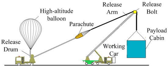
Figure 1.
Schematic diagram of the high-altitude balloon release process.
One day prior to each experiment, a small meteorological balloon was launched to profile high-altitude wind conditions. Analysis of the acquired data determined flight suitability. All equipment and tools underwent thorough inspection 24 h before the scheduled launch. Felt cloth was deployed on crane surfaces to protect the payloads during handling. Concurrently, formal applications for the requisite airspace and flight plan approval—specifying flight altitude, duration, and operational area—were submitted to the relevant air traffic control authorities.
On the day of the experiment, an additional small weather balloon was released to obtain the most recent high-altitude and surface wind field data. Based on the real-time wind speed, wind direction, and forecast data, the precise positions for the distribution roller, launch vehicle, and helium venting were determined. The standardized operational procedure is outlined below:
- Position the balloon containment box at the designated location. Connect the helium filling hose, incorporating a helium flow meter. Deploy felt cloth from the balloon to the launch vehicle.
- Extract the high-altitude balloon from its container. Guide the inflatable section of the balloon around the distribution roller, extending the remainder.
- Remove the protective film from the balloon. Connect the parachute to the balloon’s base and attach the payload cabin to the suspension cable.
- Install an air pressure soft collar beneath the balloon, positioned 1 m below the inflation tube on the release roller. Attach three wind taps uniformly.
- Execute a comprehensive self-test of the payload cabin systems. This includes verification of the measurement and control link, Iridium satellite data return functionality for in-cabin positioning, remote cut-down command reception, GPS lock status, radar transponder operation, system voltage, internal temperature, ballast valve altitude settings (1 and 2), flight control computer system time synchronization, exhaust valve remote control, payload functional checks, data transmission tests, and monitoring camera operation.
- Remove the remaining protective film from the balloon tail. Connect the power supply cable for the cut-down device and set the timers for both the internal and external cutters. After the experiment is completed, the cable connecting the high-altitude balloon and the payload cabin will be cut, allowing the high-altitude balloon to be released and the payload cabin to land. This cutting process can be accomplished via a command, or it can be triggered automatically when the flight time reaches the duration set on the timer in case of communication interruption.
- Issue the inflation command to open the helium valve. During initial inflation, the balloon apex is stabilized using the handle on the head flange. Once sufficient helium is loaded, release the balloon head. Sequentially release wind breaks as the balloon envelope expands.
- Issue the command to initiate the launch sequence. Activate the crane, configure all systems to ‘ready-for-launch’ status, and confirm the nominal status of all subsystems and payloads.
- Release the drum fuse, open the drum, and start the crane. Adjust the launch angle based on real-time wind speed and direction while simultaneously controlling payload cabin swing using the restraint lines. Observe balloon behavior from the crane side. When the balloon floats within a 5 to 10-degree arc in front of the crane, issue the final launch command, release the restraint lines, and complete the launch.
- Based on the ascent rate, determine the necessity and timing for ballast tank jettisoning. Deactivate the radar transponder. Perform real-time landing point prediction. Decide on landing declaration based on the proximity of the predicted landing point to airspace boundaries and ground conditions. Upon approval, execute the landing sequence: enable and activate the cut-down device, monitor descent status, reactivate the radar transponder, and report the final landing position.
- Upon cabin landing, rapidly process multiple location data sources (line-of-sight link, two Iridium satellites, and signal strength) to determine the precise landing site for recovery operations. First, secure the parachute post-landing and disconnect it from the payload cabin to prevent wind-induced dragging and secondary damage. Subsequently, power down all systems, secure the recovery site, collect image data, and proceed with subsequent operations.
2.1. Simulated Meteorite Landing Experiment (HH-19-6)
The HH-19-6 experiment was designed to simulate meteorite landings, supporting the analysis of organism survival in the near-space environment and the assessment of impact effects on potential life forms carried within meteorites [9]. This experiment utilized the near-space balloon platform to investigate the plausibility of interstellar (or interplanetary) panspermia by replicating the meteorite entry and Earth impact process. The mechanical design of the simulated meteorite ejection system is depicted in Figure 2; the system contains 8 cavities for storing simulated meteorites and a central cavity for installing a high-definition camera (resolution: 1920 × 1080 pixels, frame rate: 30 fps) to record the release process.
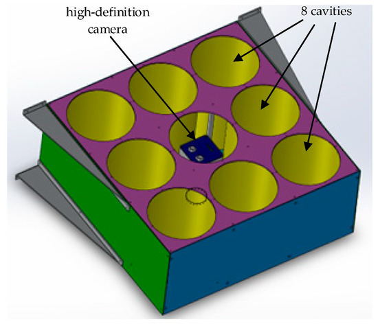
Figure 2.
Mechanical design of simulated meteorite throwing system.
The descent of simulated meteorites carrying biological material through the atmosphere subjects them to extreme environmental stressors, including rapid temperature fluctuations, intense radiation, pressure changes, hypoxia, and extreme desiccation [10]. While most biological materials would sustain fatal damage, a residual fraction of organisms or biomarkers might persist. Analysis of biological traces on the surfaces and interiors of the recovered simulated meteorites allows for an estimation of the potential for life dispersal via meteoritic transfer through interplanetary space [11].
The fully assembled physical system is shown in Figure 3a. The ejection system accommodates eight simulated meteorites, fabricated via 3D printing, as shown in Figure 3b. The control module on the right facilitates command transmission and state monitoring. Select simulated meteorites were equipped with high-precision positioning devices, enabling real-time recording of altitude, velocity, and other parameters during descent, with data transmitted wirelessly to the ground station. Other units contained identifiable microbial samples for post-recovery analysis.
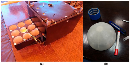
Figure 3.
Physical implementation of the simulated meteorite ejection system. (a) Fully assembled ejection system; (b) 3D-printed simulated meteorite units.
2.2. Atmospheric In Situ Detection and Descent Experiment (HH-19-7)
The HH-19-7 mission conducted prolonged in situ and vertical sounding observations within the stratosphere. The objective was to acquire multi-parameter datasets to study the distribution and short-term variability of key atmospheric dynamic, chemical, and radiative parameters over the Qinghai–Tibet Plateau [12]. Specifically, HH-19-7 aimed to elucidate stratosphere–troposphere exchange mechanisms modulated by the South Asian High anticyclone, deploying in situ atmospheric sensors and dropsonde devices in the plateau’s core region. The primary scientific payloads for HH-19-7 included dropsonde units, a lightning imager, and various in situ detection sensors. The dropsondes provided vertical profiles of standard meteorological parameters (temperature, humidity, pressure, wind direction, and speed), enabling characterization of atmospheric parameter stratification. The lightning imager delivered large-scale spatial distribution data on lightning activity. An aerosol particle sensor supplied information on aerosol number concentration and size distribution. Additional in situ sensors measured temperature, humidity, pressure, wind, solar radiation, infrared radiation, and ultraviolet radiation.
The mechanical design of the HH-19-7 payload cabin, illustrating the integration of all experimental payloads, is shown in Figure 4. The physical implementation of the HH-19-7 experiment system is presented in Figure 5, comprising two primary sections: an upper flight control cabin and a lower payload cabin. The flight control cabin’s functions included real-time monitoring of balloon position and attitude, flight altitude control, execution of the balloon–cabin separation command, and broadcasting of cabin position information post-landing. The payload cabin provided a controlled environment for the scientific instruments, furnishing power, data storage, data transmission, status monitoring, and video surveillance capabilities. The attitude accuracy of roll/pitch was 0.1°, the attitude accuracy of heading was 0.5°, the temperature in the payload cabin during the daytime ranged from 10 to 30 °C, and the outside temperature was −50 °C [13].
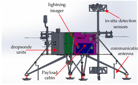
Figure 4.
Mechanical design of HH-19-7 payload cabin.
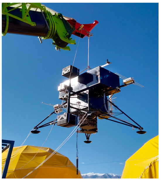
Figure 5.
Physical design of HH-19-7 experiment system.
2.3. Geomagnetic Storm Environment Comprehensive Detection Experiment (HH-19-8)
The HH-19-8 mission performed comprehensive exploration of the near-space environment during geomagnetic storm conditions. It aimed to acquire critical data on the atmospheric, electromagnetic, and radiation environments at an approximately 20 km altitude during geomagnetic storms initiated by solar coronal hole high-speed streams, supporting project goals for breakthroughs in understanding near-space environmental changes and their response to geomagnetic activity [14]. HH-19-8 employed a high-altitude balloon to transport a suite of in situ detection payloads—including atmospheric, electromagnetic, and neutron radiation detectors—to near space for comprehensive observation. The scientific payloads encompassed an air conductivity meter, a ground electric field meter, an electromagnetic field detector, a wide-energy spectrum neutron detector, a neutron radiation effects detector, a NOx gas analyzer, an ozone detector, and an acoustic instantaneous anemometer, among others. The mechanical design of the HH-19-8 payload cabin, showing the installation of all payloads, is depicted in Figure 6.
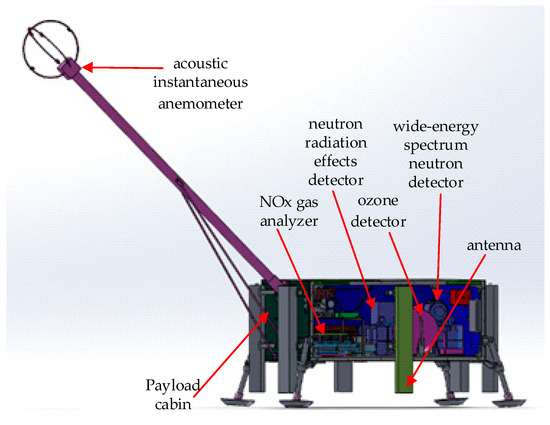
Figure 6.
Mechanical design of HH-19-8 payload cabin.
The air conductivity meter provided measurements with a resolution of at least 10−15 S/m. The electromagnetic field detector acquired electric field vector, magnetic field vector, and scalar measurements. The wide-energy spectrum neutron detector characterized the neutron energy spectrum across a range of 0.025 eV to 20 MeV. The neutron radiation effect detector monitored single-event effects induced by atmospheric neutrons. The atmospheric NOx gas analyzer quantified concentrations of NO, NO2, and NOx. The sonic instantaneous anemometer measured in situ, instantaneous 3D wind fields, temperature, humidity, and pressure. The GNSS atmospheric sounder derived profiles of atmospheric temperature, pressure, humidity, and total precipitable water vapor. The ground electric field meter primarily detected the vertical component of the electric field (0–20 km altitude). The physical implementation of the HH-19-8 experiment system is shown in Figure 7; note the external mounting of the air conductivity meter on an extended boom.
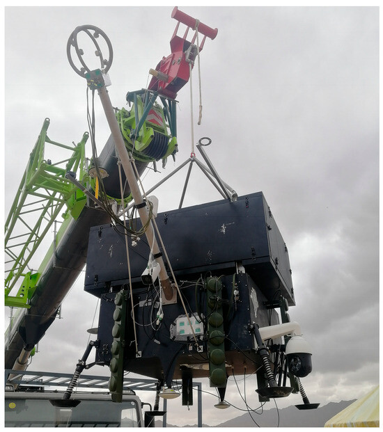
Figure 7.
Physical design of HH-19-8 experiment system.
2.4. Biological Spectroscopy Experiment (HH-19-9)
The HH-19-9 mission conducted biological exposure experiments and acquired near-space ultraviolet (UV) radiation data, investigating the effects of near-space exposure on biological samples and its correlation with the measured UV radiation environment [15,16]. HH-19-9 utilized a high-altitude balloon to transport a gas analysis and sampling system, a biological exposure experimental device, and a UV spectrometer into near space, focusing on atmospheric environment characterization, UV radiation measurement, and its impact on representative organisms. The mechanical design of the HH-19-9 payload cabin, illustrating the integrated payloads, is shown in Figure 8.
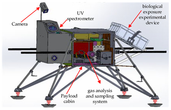
Figure 8.
Mechanical design of HH-19-9 payload cabin.
The biological exposure experimental device investigated the combined effects of the atmospheric and UV radiation environment on representative organisms. The UV spectrometer characterized the near-space UV background, including the altitude-dependent distribution of UV spectral intensity above 20 km and its variation with the solar zenith angle. The gas analysis and sampling system collected discrete gas samples at 3 km intervals upon entering the stratosphere (~15 km), acquiring a minimum of five valid samples throughout the flight. The physical implementation of the HH-19-9 experiment system is presented in Figure 9.
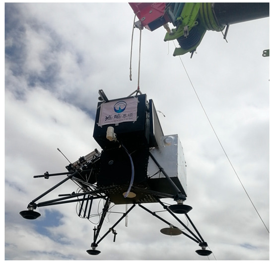
Figure 9.
Physical configuration of HH-19-9 experiment system (HongHu Project in Chinese).
3. Results
The HongHu project successfully executed four distinct large-scale near-space scientific campaigns on the Qinghai–Tibet Plateau, involving the launch of eight high-altitude balloons carrying four different sets of scientific exploration equipment. The overall Qinghai–Tibet Plateau exploration effort spanned two months and involved over 100 participants. The flight schedule was as follows: HH-19-6 was launched once; HH-19-7 was launched twice (designated A and B); HH-19-8, comprising two distinct payload cabin configurations (Q5 and Q20), each flew twice; and HH-19-9 was launched once.
The inaugural mission, HH-19-7A, was completed on 23 July, achieving a flight duration of 10 h 16 min and a peak altitude of 21.6 km. HH-19-6 was conducted on 31 July, reaching a maximum altitude of 8 km with a flight time of 2 h 10 min. HH-19-7B was completed on 16 August, demonstrating extended endurance with a flight duration of 30 h 53 min and a peak altitude of 23 km. On 27 August, the HH-19-8A-Q20 and HH-19-8A-Q5 balloons were launched sequentially with an interval of less than 30 min. HH-19-8A-Q20 flew for 3 h 50 min, reaching 25.2 km, while HH-19-8A-Q5 flew for 3 h 52 min, reaching 22.8 km. On 1 September, the HH-19-8B-Q5 configuration completed its second flight, lasting 17 h 30 min and reaching 22.8 km. On 5 September, HH-19-8B-Q20 completed its second flight, lasting 3 h 35 min and reaching 25.2 km. The final mission, HH-19-9, was completed on 9 September, with a flight time of 5 h 5 min and a maximum altitude of 32.3 km. A summary of all eight flights is provided in Table 1.

Table 1.
Summary of the eight flight experiments conducted under the HongHu project.
The deployed balloons were large zero-pressure types, with volumes of 5000 m3, 20,000 m3, and 50,000 m3, corresponding to payload capacities ranging from approximately 100 kg to 400 kg. Specifics include the following: HH-19-6 used a 5000 m3 balloon carrying 96 kg; HH-19-7 used 20,000 m3 balloons carrying 325 kg; HH-19-8-Q5 used 5000 m3 balloons carrying 157 kg; HH-19-8-Q20 used 20000 m3 balloons carrying 378 kg; and HH-19-9 used a 50,000 m3 balloon carrying 253 kg.
The flight trajectories for all eight experiments are plotted in Figure 10. The landing sites were primarily clustered into two geographical areas. Missions with longer durations (HH-19-7A, HH-19-7B, and HH-19-8B-Q5, all exceeding 10 h) resulted in landing points significantly distant from the launch site. The shorter-duration missions exhibited more concentrated landing patterns, as detailed in the close-up view in Figure 11.
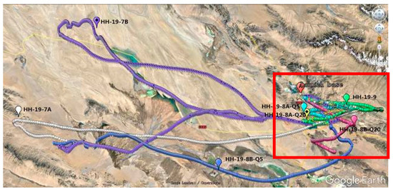
Figure 10.
Composite flight route map for the eight experiments.
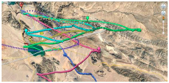
Figure 11.
Detailed flight route map for the shorter-duration experiments.
3.1. HH-19-6 Experiment Results
The HH-19-6 experiment was successfully conducted on 31 July. Given its focused objective involving a single simulated meteorite ejection device, a dedicated, complex payload cabin was not utilized; the ejection control module was integrated directly with the balloon’s standard flight control cabin. Owing to this simplified configuration and the relatively low target altitude, the total experiment duration was brief, at 2 h and 10 min. The launch sequence is depicted in Figure 12.
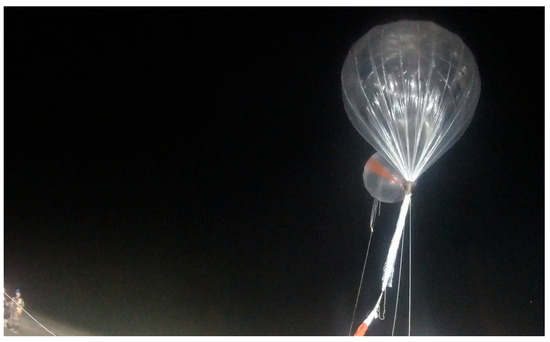
Figure 12.
Releasing process of HH-19-6 experiment.
Upon reaching the target altitude of 8 km, the ground console issued the ejection command, triggering the sequential release of the simulated meteorites according to the pre-programmed sequence. The ejection mechanism utilized a nickel–chromium alloy wire securing the ejection cabin’s baseplate. Applying electrical current heated and subsequently melted the wire, causing the baseplate to open and release the simulated meteorite. The cabin door opening process is captured in Figure 13.
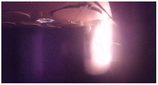
Figure 13.
Cabin door opening process in HH-19-6 experiment.
After the experiment, the flight control cabin was separated from the balloon and descended safely under parachute. The landing site was fortuitously located near an access road, facilitating recovery, as shown in Figure 14. The simulated meteorites were successfully located using their transmitted positional data. As shown in Figure 15, several meteorites sustained significant fragmentation upon impact due to the high kinetic energy.
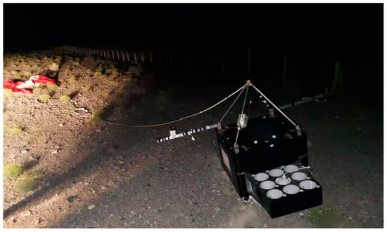
Figure 14.
Landing state of HH-19-6 experiment.
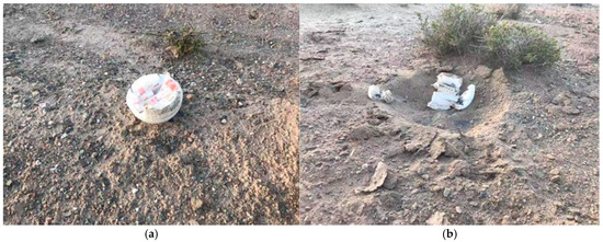
Figure 15.
Post-recovery state of the simulated meteorites from HH-19-6: (a) intact unit; (b) shattered unit demonstrating high-impact forces.
3.2. HH-19-7A Experiment Results
The HH-19-7A experiment was conducted on 23 July. Operations commenced at 05:15 local time, with balloon launch occurring at 06:45, as captured by a ground camera and shown in Figure 16. The balloon achieved the target altitude of approximately 21.6 km after a 65 min ascent. It maintained level flight above 20 km for approximately 10 h before initiating descent. Following a brief period of level flight between 16 km and 17 km, the balloon–payload connection was severed. The balloon continued ascending until its rupture, while the payload cabin descended under gravity, with the parachute deploying to decelerate the descent.
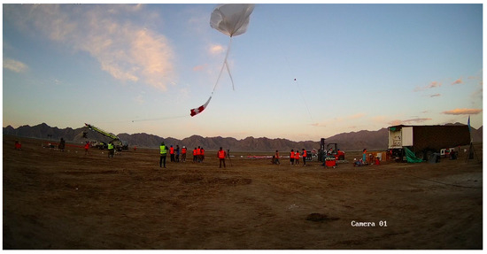
Figure 16.
Releasing process of HH-19-7A experiment.
Throughout the flight, the dropsonde devices, lightning imager, and other in situ sensors operated as commanded and acquired data nominally. Figure 17 shows the payload cabin at its landing site, indicating a successful and upright touchdown.
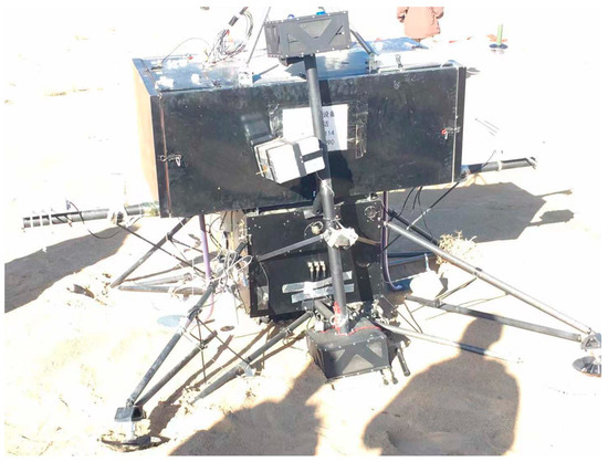
Figure 17.
Payload cabin landing state of HH-19-7A experiment.
The flight trajectory of HH-19-7A is illustrated in Figure 18, with point ‘A’ marking the launch site and point ‘B’ the landing site. The altitude profile recorded during the flight is presented in Figure 19. Note the data gap during the final landing phase, resulting from the automatic safety power-down sequence.
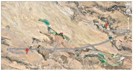
Figure 18.
Flight trajectory of HH-19-7A experiment.
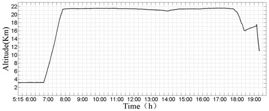
Figure 19.
Recorded flight altitude profile for the HH-19-7A experiment.
Based on this experiment, the Institute of Atmospheric Physics, Chinese Academy of Sciences (CAS), has systematically clarified the stratosphere–troposphere material exchange process over the Qinghai–Tibet Plateau and the coupling process between the Qinghai–Tibet Plateau and the global atmospheric chemistry and climate based on the data obtained from this experiment [17,18].
3.3. HH-19-8A Experiment Results
The HH-19-8A campaign involved the near-simultaneous launch of two balloons, HH-19-8A-Q20 and HH-19-8A-Q5. The launch time is determined based on a comprehensive analysis of multiple factors, including the predicted geomagnetic storm date, weather conditions, airspace restrictions, and other relevant elements. Therefore, the test launch time was scheduled to be 27 August 2019. Operations began at 03:00, with the HH-19-8A-Q20 balloon launching at 03:40, followed by the HH-19-8A-Q5 balloon at approximately 04:10. The dual launch operation is depicted in Figure 20, showing the larger HH-19-8A-Q20 balloon (right) and the smaller HH-19-8A-Q5 balloon (left).
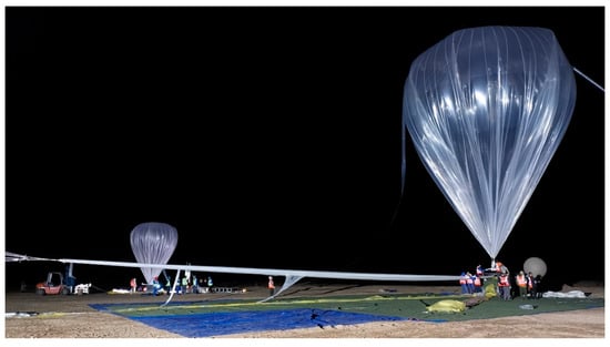
Figure 20.
Dual-balloon launch sequence for the HH-19-8A experiment.
Figure 21 shows the landed state of the HH-19-8A-Q5 payload cabin, which tipped over upon landing due to the soft, sandy terrain, although the payloads remained secure.
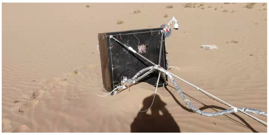
Figure 21.
Landed state of the HH-19-8A-Q5 payload cabin, showing a tip-over on soft sand.
The flight trajectories for HH-19-8A-Q20 and HH-19-8A-Q5 are shown in Figure 22 and Figure 23, respectively, revealing similar flight paths and proximate landing sites. The corresponding altitude profiles are provided in Figure 24 and Figure 25, demonstrating controlled flight operations and similar altitude–time histories for both vehicles.
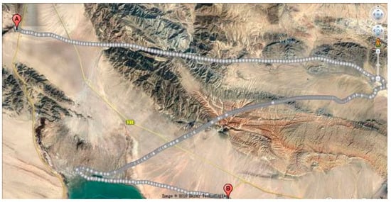
Figure 22.
Flight trajectory of the HH-19-8A-Q20 experiment.
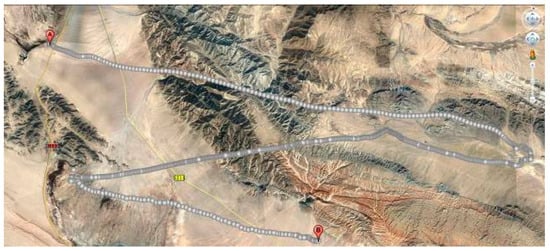
Figure 23.
Flight trajectory of the HH-19-8A-Q5 experiment.
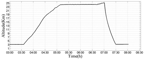
Figure 24.
Recorded flight altitude profile for the HH-19-8A-Q20 experiment.
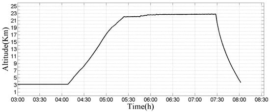
Figure 25.
Recorded flight altitude profile for the HH-19-8A-Q5 experiment.
Based on this experiment, the National Space Science Center of the Chinese Academy of Sciences (CAS) obtained results regarding the variation characteristics of transient wind fields in near space, neutron radiation effects, the impact of solar flares on ultraviolet radiation in near space, and geomagnetic anomalies for the first time [19]. The solar ultraviolet radiation environment data obtained by the Solar Ultraviolet Spectrometer provides a reference for atmospheric retrieval in near space [20,21]. The Atmospheric NOx Gas Analyzer achieved in situ measurement of atmospheric NOx in the troposphere (from 5 km to 30 km in the stratosphere) and obtained scientific detection data on the mixing ratios of NO, NO2, and NOx over the Qinghai–Tibet Plateau [22].
3.4. HH-19-9 Experiment Results
The final mission, HH-19-9, was successfully completed on 9 September. Operations commenced at 03:30, with the balloon launch occurring at 05:20, as shown in Figure 26. The balloon reached the target altitude of ~31.6 km after a 2-h ascent and maintained level flight above 30 km for approximately 2.5 h.
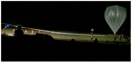
Figure 26.
Releasing process of HH-19-9 experiment.
During level flight, an upward-looking surveillance camera documented the balloon’s envelope, as shown in Figure 27. Figure 28 shows the payload cabin after landing. The cabin tipped over upon impact due to uneven terrain, but all internal payloads were reported secure and undamaged.
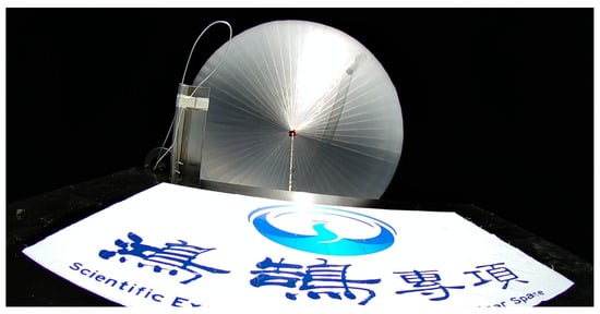
Figure 27.
Image of the balloon envelope captured by the upward-facing camera during HH-19-9 level flight (HongHu Project in Chinese).
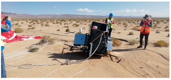
Figure 28.
Landed state of the HH-19-9 payload cabin, showing a tip-over on uneven ground.
The flight trajectory for HH-19-9 is shown in Figure 29, indicating a well-controlled flight path and a suitable landing location. The altitude profile is presented in Figure 30, confirming a peak altitude exceeding 32 km. The data gap during final descent is again attributed to the safety power-down protocol.
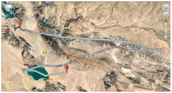
Figure 29.
Flight trajectory of the HH-19-9 experiment.
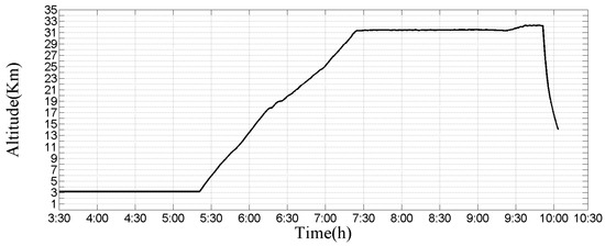
Figure 30.
Recorded flight altitude profile for the HH-19-9 experiment.
We performed the same experiment on 3 September 2020 to obtain more data by using both temperature-controlled biological exposure devices and non-temperature-controlled biological exposure devices simultaneously. The environmental adaptability of magneto tactic bacteria in the near-space environment was also tested [23,24].
4. Discussion
In this paper, we comprehensively summarized the execution and engineering outcomes of four large-scale near-space scientific experiments conducted under the HongHu project on the Qinghai–Tibet Plateau. All campaign elements—including high-altitude balloon operations, scientific payload functionality, payload cabin performance, and equipment recovery—were successfully demonstrated.
The results presented herein primarily focus on the engineering aspects of the missions, encompassing parameters such as thermal variations during flight, payload cabin attitude dynamics, and video surveillance feeds. We posit that the extensive flight data acquired through these campaigns provides valuable engineering insight for future near-space exploration endeavors and will inform the design of robust near-space payloads. The deployment of large zero-pressure balloons, with volumes of up to 50,000 m3 and payload capacities of up to 400 kg, in a sustained, multi-campaign effort represents a significant operational achievement. The engineering experience and empirical data gathered are considered highly valuable for the community as comparable intensive, large-balloon campaigns remain relatively uncommon globally.
By comparing the results of this experiment with those of other international experiments (Sunrise mission, BLAST-Pol, STO, and HEROES) [25,26,27,28], covering aspects such as maximum flight duration, optical payload performance, and stable pointing performance, it can be seen that there is still a gap between our experimental results and those of world-leading teams. Additionally, different experiments have distinct objectives: our experiments involve a wider variety of types and strong exploratory nature. Nevertheless, we will continue to conduct more work in the field of near-space balloon-borne observation.
5. Conclusions
The experimental series described involved the integration and flight testing of more than twenty distinct payloads developed by collaborating institutions. Preliminary analysis of the acquired datasets has already facilitated the publication of several high-impact research papers by the participating teams. Building upon the foundational success of these initial campaigns, future work will involve continued collaboration with partner institutions to conduct further scientific exploration experiments in near space. These ongoing efforts are expected to significantly advance our understanding of the complex processes characterizing the near-space environment.
Author Contributions
Conceptualization, M.H. and L.Q.; methodology, W.Z.; software, Z.Z.; validation, Z.Z., W.Z. and G.W.; formal analysis, Y.Z.; investigation, L.Q.; resources, M.H.; data curation, Z.Z.; writing—original draft preparation, Z.W.; writing—review and editing, W.Z. and Y.S.; visualization, Y.S.; supervision, M.H.; project administration, L.Q.; funding acquisition, L.Q. All authors have read and agreed to the published version of the manuscript.
Funding
This research was funded by the Future Star Project of the Chinese Academy of Sciences Aerospace Information Institute and Youth Innovation Promotion Association, CAS.
Institutional Review Board Statement
Not applicable.
Informed Consent Statement
Not applicable.
Data Availability Statement
The original contributions presented in this study are included in the article. Further inquiries can be directed to the corresponding author.
Conflicts of Interest
The authors declare no conflicts of interest.
Abbreviations
The following abbreviations are used in this manuscript:
| CAS | Chinese Academy of Sciences |
| UAV | Unmanned Aerial Vehicle |
| GPS | Global Positioning System |
| GNSS | Global Navigation Satellite System |
| UV | Ultraviolet |
| NOx | Nitrogen Oxides (NO + NO2) |
| BLAST-Pol | Balloon-borne Large Aperture Submillimeter Telescope for Polarimetry |
| STO | Stratospheric Terahertz Observatory |
| HEROES | High Energy Replicated Optics to Explore the Sun |
References
- Xapsos, M.A.; O’Neill, P.M.; O’Brien, T.P. Near-Earth Space Radiation Models. IEEE Trans. Nucl. Sci. 2013, 60, 1691–1705. [Google Scholar] [CrossRef]
- Bourdarie, S.; Xapsos, M. The Near-Earth Space Radiation Environment. IEEE Trans. Nucl. Sci. 2008, 55, 1810–1832. [Google Scholar] [CrossRef]
- Cathey, H.M. The NASA super pressure balloon—A path to flight. Adv. Space Res. 2009, 44, 23–38. [Google Scholar] [CrossRef]
- Wang, W.Q.; Cai, J.Y.; Peng, Q.C. Near-space microwave radar remote sensing: Potentials and challenge analysis. Remote Sens. 2010, 2, 717–739. [Google Scholar] [CrossRef]
- Tu, Y.G.; Xu, G.N.; Yang, X.Y.; Zhang, Y.; Li, Z.; Su, R.; Luo, D.; Yang, W.; Miao, Y.; Cai, R.; et al. Mixed-cation perovskite solar cells in space. China Phys. Mech. Astron. 2019, 62, 974221. [Google Scholar] [CrossRef]
- Cai, R.; Yang, Y.C.; Jiang, L.H.; Zhang, T.H.; Xu, G.N.; Zhang, X.Q.; Zhou, J.H.; Miao, J.G.; Gong, Z.Q.; Wang, S.; et al. Research progress of High-altitude Scientific Balloons in Chinese Academy of Sciences. Natl. Remote Sens. Bull. 2025, 29, 1502–1514. [Google Scholar] [CrossRef]
- Huang, W.N.; Zhang, X.J.; Li, Z.B.; Wang, S.; Huang, M.; Cai, R. Development status and application prospect of near space science and technology. Sci. Technol. Rev. 2019, 37, 46–62. [Google Scholar]
- Lin, J.; Song, T.F.; Sun, M.Z.; Zhang, T.; Xu, F.Y.; Wang, J.X.; Fu, Y.; Li, Y.; Kang, K.F.; Huang, M.; et al. A 50-mm balloon-borne white-light coronagraph: I. Basic structure and experiments on the ground. Sci. Sin. 2023, 53, 259611. [Google Scholar]
- Horneck, G.; Klaus, D.M.; Mancinelli, R.L. Space microbiology. Microbiol. Mol. Biol. Rev. 2010, 74, 121–156. [Google Scholar] [CrossRef]
- Mileikowsky, C.; Cucinotta, F.A.; Wilson, J.W.; Gladman, B.; Horneck, G.; Lindegren, L.; Melosh, J.; Rickman, H.; Valtonen, M.; Zheng, J.Q. Natural transfer of viable microbes in space. Icarus 2000, 145, 391–427. [Google Scholar] [CrossRef]
- Clark, B.C. Planetary interchange of bioactive material: Probability factors and implications. Orig. Life Evol. Biosph. 2001, 31, 185–197. [Google Scholar] [CrossRef]
- Randel, W.J.; Park, M. Diagnosing observed stratosphere-troposphere exchange with a trajectory model. J. Atmos. Sci. 2019, 76, 1885–1902. [Google Scholar]
- Wang, Z.; Huang, M.; Qian, L.; Zhao, B.; Wang, G. High-Altitude Balloon-Based Sensor System Design and Implementation. Sensors 2020, 20, 2080. [Google Scholar] [CrossRef]
- Baker, D.N.; Kanekal, S.G.; Hoxie, V.C.; Henderson, M.G.; Li, X.; Spence, H.E.; Elkington, S.R.; Friedel, R.H.W.; Goldstein, J.; Hudson, M.K.; et al. A long-lived relativistic electron storage ring embedded in Earth’s outer Van Allen belt. Science 2013, 340, 186–190. [Google Scholar] [CrossRef] [PubMed]
- Nicholson, W.L.; Schuerger, A.C.; Setlow, P. The solar UV environment and bacterial spore UV resistance: Considerations for Earth-to-Mars transport by natural processes and human spaceflight. Mutat. Res. Mol. Mech. Mutagen. 2005, 571, 249–264. [Google Scholar] [CrossRef] [PubMed]
- Rettberg, P.; Rabbow, E.; Panitz, C.; Horneck, G. Biological space experiments for the simulation of Martian conditions: UV radiation and Martian soil analogues. Adv. Space Res. 2004, 33, 1294–1301. [Google Scholar] [CrossRef] [PubMed]
- Zhang, J.Q.; Wu, X.; Liu, S.; Bai, Z.X.; Xia, X.G.; Chen, B.; Zong, X.M.; Bian, J.C. In situ measurements and backward-trajectory analysis of high-concentration, fine-mode aerosols in the UTLS over the Tibetan Plateau. Environ. Res. Lett. 2019, 14, 124068. [Google Scholar] [CrossRef]
- Li, L.; Su, J.F.; Chen, T.; Ti, S.; Wu, H.; Luo, J.; Li, W.; Li, R.K. Measurement of atmospheric conductivity on the Qinghai-Tibet Plateau in China. Meteorol. Atmos. Phys. 2022, 134, 40. [Google Scholar] [CrossRef]
- Hu, X.; Wei, F.; Li, L.; Chen, T.; Zhou, B.; Song, L.; Wei, F.; Wang, X.Y.; Zhu, X.; Tao, M.Z. In-situ environmental detecting payloads onboard the floating platform in near-space. Aerosp. Technol. 2022, 447, 95–104. [Google Scholar]
- Zhang, X. Simulation of Solar Ultraviolet Radiation Environment in Near Space and Analysis of Topographic Difference. Chin. J. Space Sci. 2022, 42, 1129–1136. (In Chinese) [Google Scholar] [CrossRef]
- An, Y.; Wang, X.H.; Ye, H.H.; Shi, H.L.; Wu, S.C.; Li, C.; Sun, E.C. Study on the Ultraviolet Radiation Environment and Influencing Factors in Near Space. Acta Photonica Sin. 2024, 53, 0301001. [Google Scholar]
- Wang, X.Y.; Du, D.; Yan, Z.A.; Zhang, A.B.; Hu, X. In situ observation of atmospheric NOx over Qinghai-Tibet Plateau by Scientific Experiment System in Near SpaceProgram. Chin. Sci. Bull. 2022, 67, 3348–3356. (In Chinese) [Google Scholar] [CrossRef]
- Lin, W. Life in the near space and implications for astrobiology. Chin. Sci. Bull. 2020, 65, 1295–1304. [Google Scholar] [CrossRef]
- Liu, J.; Zhang, W.; He, K.; Liu, L.; Wang, C.; Jiang, Y.; Ma, S.; Tian, J.; Li, Y.; Zhang, T.; et al. Survival of the magnetotactic bacterium Magnetospirillum gryphiswaldense exposed to Earth’s lower near space. Sci. Bull. 2022, 67, 1335–1339. [Google Scholar] [CrossRef] [PubMed]
- Barthol, P.; Gandorfer, A.; Solanki, S.K.; Schüssler, M.; Chares, B.; Curdt, W.; Deutsch, W.; Feller, A.; Germerott, D.; Grauf, B.; et al. The Sunrise Mission. Sol. Phys. 2011, 268, 1–34. [Google Scholar] [CrossRef]
- Pascale, E. The Balloon-borne Large Aperture Submillimetre Telescope (BLAST) and BLASTPol. Proc. Int. Astron. Union 2012, 8, 154–160. [Google Scholar] [CrossRef]
- Chauvin, M.; Friis, M.; Jackson, M.; Kawano, T.; Kiss, M.; Mikhalev, V.; Ohashi, N.; Stana, T.; Takahashi, H.; Pearce, M. Calibration and performance studies of the balloon-borne hard X-ray polarimeter PoGO+. Nucl. Instrum. Methods Phys. Res. 2017, 859, 125–133. [Google Scholar] [CrossRef]
- Gaskin, J.; Apple, J.; Chavis, K.S.; Dietz, K.; Holt, M.; Koehler, H.; Lis, T.; O’Connor, B.; Otero, M.R.; Pryor, J. High Energy Replicated Optics to Explore the Sun: Hard X-ray balloon-borne telescope. In Proceedings of the 2013 IEEE Aerospace Conference, Big Sky, MT, USA, 2–9 March 2013. [Google Scholar]
Disclaimer/Publisher’s Note: The statements, opinions and data contained in all publications are solely those of the individual author(s) and contributor(s) and not of MDPI and/or the editor(s). MDPI and/or the editor(s) disclaim responsibility for any injury to people or property resulting from any ideas, methods, instructions or products referred to in the content. |
© 2025 by the authors. Licensee MDPI, Basel, Switzerland. This article is an open access article distributed under the terms and conditions of the Creative Commons Attribution (CC BY) license (https://creativecommons.org/licenses/by/4.0/).