1. Introduction
With the rapid development of autonomous driving technology and urban logistics, unmanned delivery vehicles have become a crucial component in the construction of smart cities and intelligent transportation systems as important carriers for automating last-mile delivery [
1]. Unmanned delivery vehicles not only improve delivery efficiency and reduce labor costs but also effectively alleviate urban traffic congestion and reduce environmental pollution, offering broad application prospects and significant social value [
2]. However, these vehicles face numerous challenges when operating in complex and dynamic urban road environments.
Accurate trajectory tracking and speed control are core technologies to ensure the safe and efficient operation of unmanned delivery vehicles. The ability to track trajectories directly affects whether the vehicle can accurately and safely follow planned paths [
3], while speed control impacts vehicle stability under varying road conditions and the quality of goods transportation. However, existing studies often simplify trajectory tracking as a lateral control problem under constant or predefined speeds. Tracking algorithms typically rely on fixed or preset speed profiles, paying little attention to dynamic speed profile adjustments in response to road curvature variations. Such simplifications can lead to abrupt speed changes and degraded tracking accuracy, especially under conditions of severe curvature changes and complex traffic environments. Achieving high-precision and robust motion control under these conditions remains a key challenge for the deployment of unmanned delivery vehicle technologies.
Existing trajectory tracking strategies are generally categorized into geometry-based control and feedback-based control methods. The former, represented typically by Pure Pursuit [
4] and Stanley [
5] controllers, primarily utilize the geometric features of the desired path to compute the front wheel steering angle. For instance, the Pure Pursuit algorithm guides the vehicle by constructing a circular arc between the vehicle’s current position and a look-ahead point on the path [
6]. Such methods are widely adopted due to their simplicity and computational efficiency. However, such methods typically treat the vehicle as a point mass or only consider simple kinematics, without explicitly taking into account the vehicle’s actual driving conditions, such as tire slip and center of mass skid, nor do they handle the issues of road adhesion and friction limits. Therefore, in situations such as high-speed driving, changes in road curvature, and low adhesion, it is prone to generate steering oscillation and overshoot, resulting in limitations on control accuracy and stability.
Feedback-based control strategies that leverage real-time system state feedback to effectively manage model uncertainties and external disturbances [
7]. Among these, the classical PID [
8] controller is widely adopted due to its structural simplicity and strong robustness, making it a prevalent choice in trajectory tracking applications [
9,
10]. Nevertheless, traditional PID controllers depend heavily on empirical parameter tuning and often fail to deliver optimal performance in nonlinear, time-varying systems. This limitation becomes especially evident under complex and dynamic driving scenarios, where advanced gain scheduling or adaptive tuning mechanisms are necessary to maintain control efficacy. To enhance control performance, more advanced control theories have been introduced. For example, Sliding Mode Control (SMC) [
11] has been applied to improve vehicle path-tracking capability by modulating the braking torque on the left and right wheels to generate additional yaw moments [
12]. Meanwhile, the Linear Quadratic Regulator (LQR) is utilized to design an optimal lateral controller, which effectively improves lateral control accuracy by minimizing a quadratic cost function composed of state errors and control inputs [
13].
However, a vehicle operating in real-world driving scenarios is a highly nonlinear and complex system subject to numerous physical constraints, such as tire adhesion limits and actuator saturation [
14]. Traditional control methods face inherent challenges in explicitly handling these complex constraints. In contrast, MPC [
15] has emerged as a research focus in trajectory tracking due to its ability to predict future system dynamics over a finite horizon and solve an online optimization problem that accounts for system models and multiple constraints, thereby yielding optimal control inputs at each time step [
16]. This anticipatory control approach demonstrates superior performance in managing nonlinear, multivariable, and strongly constrained systems. Representative works include model predictive control based on linear time-varying models, which significantly improves computational efficiency while ensuring precise tracking of key states such as the sideslip angle and yaw rate [
17]; and variable prediction horizon model predictive control with the front wheel angle as the control variable, achieving a good balance between tracking accuracy and steering smoothness [
18].
In autonomous driving trajectory tracking tasks, achieving precise path following is only a fundamental objective. A more critical challenge lies in maintaining tracking accuracy while addressing vehicle dynamic stability issues induced by changes in road geometry, particularly in high-curvature curves. Focusing solely on minimizing lateral tracking errors often overlooks the physical limits of the tires, which can lead to lateral tire force saturation and vehicle instability during high-speed cornering, thereby posing significant safety risks [
19]. Early research paradigms typically assumed a constant vehicle speed or employed simple empirical rules for speed adjustment, which largely decoupled longitudinal and lateral control but failed to accommodate the intrinsic stability requirements imposed by dynamic changes in road curvature. To overcome this limitation, modern trajectory tracking control strategies increasingly emphasize adaptive speed planning and coordinated control [
20]. A prevalent approach involves incorporating curvature-based speed constraints. For instance, leveraging the friction circle theory [
21], the physical relationship among lateral acceleration, tire-road friction coefficient, and upcoming road curvature is established to compute the maximum safe speed that maintains vehicle stability online. This proactive strategy effectively mitigates tire saturation risks and enhances vehicle capability and safety under extreme driving conditions [
22].
Building upon this foundation, more advanced control frameworks have further integrated speed planning with path tracking. Gao et al. [
23] developed MPC framework that synchronously optimizes vehicle cornering speed and steering inputs based on the predicted reference path curvature within the prediction horizon, proactively mitigating instability risks associated with high-speed cornering. Another effective coordinated control paradigm is the hierarchical control architecture. For example, Chen et al. [
24] designed a hierarchical controller combining MPC and PID control, where the upper-level MPC computes the optimal front wheel steering angle for precise lateral control, while the lower-level PID speed controller accurately regulates driving and braking forces based on upper-level commands and current vehicle states. This clear division of responsibilities achieves efficient coordination of lateral and longitudinal vehicle dynamics, ensuring dynamic stability and tracking performance on varying curvature road segments.
Trajectory tracking and dynamic stability control technologies for conventional passenger cars have become increasingly mature and have found wide application in the fields of Advanced Driver-Assistance Systems (ADAS) and autonomous driving [
25]. However, this body of research has predominantly focused on high-speed driving scenarios within structured road environments. In stark contrast, research on trajectory tracking and stability control for unmanned delivery vehicles in the complex “last-mile” urban road environment (such as roads with varying curvature and low-adhesion surfaces) is relatively limited.
To address the trajectory tracking control problem encountered during the operation of unmanned delivery vehicles, this paper proposes an integrated control strategy and validates it through simulation studies. A unified trajectory tracking error model is established on the basis of vehicle dynamics, in which lateral position error and heading angle error are incorporated into a state space representation. This elevates error characterization from the geometric level to the dynamic level and provides a rigorous mathematical foundation for controller design.
This paper presents a collaborative control architecture aimed at addressing the instability issues of unmanned delivery vehicles in extreme conditions, such as sharp turns (high curvature) and slippery roads (low adhesion). The core of this architecture is to use active speed adjustment, where a PID controller dynamically adjusts the vehicle speed based on the upcoming road curvature and adhesion. This strategy establishes a crucial safety margin for the predictive steering optimization of the lateral model predictive control, thereby significantly improving the efficiency and accuracy of the trajectory tracking task. Compared with geometric control, this mode significantly improves the trajectory tracking accuracy in complex road geometries and scenarios with rapid curvature changes; at the same time, compared with traditional feedback control strategies, it more fully incorporates vehicle dynamics and stability constraints, thereby enhancing the overall driving stability.
To systematically validate the effectiveness of the proposed coordinated control architecture, a series of high-fidelity co-simulation experiments were conducted. These scenarios accurately replicated the typical extreme conditions encountered by unmanned delivery vehicles in last-mile urban delivery, such as sharp curvature variations and low-adhesion, slippery surfaces. A systematic comparison against conventional fixed-speed control strategies demonstrated that the proposed method exhibits a significant advantage in both tracking accuracy and driving stability, even under severe low-adhesion conditions, thus confirming its practical engineering feasibility.
2. Vehicle Modeling
This section details the two-degree-of-freedom (2-DOF) vehicle dynamics model, which offers a balance between computational simplicity and the accurate representation of lateral and yaw dynamics crucial for trajectory tracking. Subsequently, a corresponding trajectory tracking error model is established. These models collectively form the theoretical basis for the controller design.
2.1. Vehicle Dynamic Model
To analyze the vehicle’s lateral dynamics during trajectory tracking, this study utilizes the classical 2-DOF bicycle model. This model simplifies the vehicle by lumping the two front and two rear wheels into single front and rear wheels, respectively, as depicted in
Figure 1. It is assumed that the properties of the left and right tires are identical, leading to symmetrical motion. The model treats the vehicle as a rigid body, neglecting vertical, roll, and pitch motions, thus constraining its movement to a plane parallel to the ground. Applying Newton’s second law, the equations of motion are derived as follows [
17]:
where
denotes the vehicle mass,
represents the yaw moment of inertia,
is the yaw rate,
and
are the lateral forces at the front and rear wheels, respectively,
and
denote the distances from the vehicle’s center of gravity to the front and rear axles,
and
represent the longitudinal and lateral velocities of the vehicle,
δ is the front wheel steering angle.
Under normal driving conditions, the tires consistently operate within their elastic cornering region. Therefore, employing a linear tire model to describe the mechanical characteristics of the tires. This model assumes that the tire slip angles are small. Within this operating region, a linear relationship exists between the lateral force and the slip angle.
where
and
represent the lateral stiffness of the front and rear wheels, respectively, and
and
are the front and rear tire slip angles, respectively. The lateral deviation of the front and rear wheels can be represented in more detail. The tire slip angle is defined as the angle between the direction in which the wheel is pointing and the direction of its actual travel. The slip angles of the front and rear wheels can be calculated as follows:
2.2. Vehicle Error Model
The establishment of a precise error model is a fundamental step in the development of a motion controller for an unmanned delivery vehicle, particularly for the task of trajectory tracking. Within their typical operational context, lateral stability and control are paramount to the safe operation of these vehicles. Consequently, the vehicle’s lateral dynamics have a more pronounced impact on its overall performance compared to its longitudinal dynamics. Based on this consideration, by substituting the equations describing the tire kinematic relationships (Equations (2) and (3)) into the vehicle’s dynamic equations (Equation (1)), the model is further simplified by making a small-angle assumption, where the front steering angle
is small, such that
. The final kinetic equation is organized and rewritten in the state-space form (Equation (4)). This is performed to enable a clearer depiction of the relationship between the internal state of the system, the input, and the output.
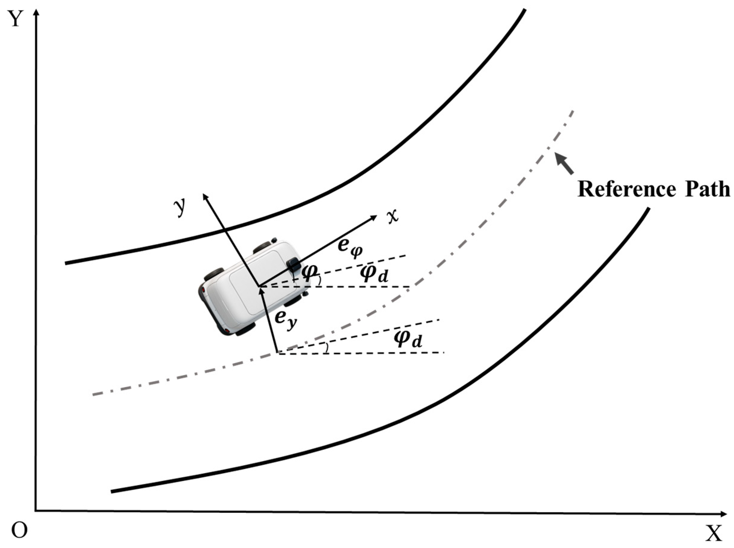
To intuitively characterize the vehicle’s deviation during trajectory tracking, this paper introduces two key metrics: the heading angle error (
) and the lateral position error (
). The heading angle error quantifies the orientation difference between the vehicle’s current heading and the desired heading. Concurrently, the lateral position error represents the displacement of the vehicle’s center of gravity from the reference trajectory. The geometric relationship between these errors is illustrated in
Figure 2, and they are mathematically defined as follows:
In the preceding definitions,
denotes the vehicle’s actual heading angle, while
represents the desired heading angle derived from the reference trajectory. By combining these error definitions with the 2-DOF vehicle dynamics model, a comprehensive state-space model for the trajectory tracking error is formulated. Within this framework, the front wheel steering angle (
δ) is selected as the control input. The state variables are chosen to capture the full error dynamics, consisting of the lateral position error, its rate of change, the heading angle error, and its rate of change. This yields the state vector
. The corresponding system dynamics are then represented as follows:
where
This error model considers both lateral position error and heading angle error during the vehicle’s tracking process, providing an intuitive and effective representation of the vehicle’s performance in trajectory tracking. It serves as a fundamental basis for subsequent controller design.
3. Controller Design
To achieve high-precision and highly stable trajectory tracking of autonomous vehicles under complex and varying road curvature conditions, this section proposes a hierarchical coordinated motion control architecture. This architecture decouples the overall tracking task into two submodules: lateral path tracking and speed control. Through efficient collaboration between these functional modules, the system ensures safety, accuracy, and smoothness during vehicle operation. The overall control system architecture is illustrated in
Figure 3.
Firstly, discrete reference trajectory points are collected based on a predefined geometric path and the reference trajectory equation, yielding a list containing lateral position, longitudinal position, and road curvature information. Using the closest-point projection method, the current reference point corresponding to the vehicle’s position is determined in real time. This module further aligns and compares the vehicle’s real-time state (including position, heading angle, and speed) with the reference point’s attributes such as position, tangent direction, curvature, and desired speed. Subsequently, it accurately computes the core state errors required for feedback control, primarily including lateral position error , heading angle error , and speed error .
At the control layer, the system integrates a PID speed tracking controller and a lateral MPC path tracking controller. The speed control module outputs vehicle driving force based on the deviation between actual and desired speeds, enabling closed-loop speed regulation. Meanwhile, the lateral control module takes real-time lateral and heading errors as inputs and employs MPC to dynamically optimize front wheel steering commands, ensuring that the vehicle can precisely follow the reference path under complex driving conditions.
3.1. Speed Controller
In existing controller designs, speed control is often set as a constant value. This simplification tends to cause vehicle sideslip in curves and exacerbates tracking errors. Therefore, in autonomous vehicle trajectory tracking tasks, dynamically planning a feasible speed profile for a given geometric path is critical to ensuring driving safety and traffic efficiency. Simply relying on a sequence of path points is insufficient to guide the vehicle; a safe speed command must be assigned at each position. One of the core aspects of speed planning is accurately calculating the curvature
k of the road, which reflects the degree of path curvature. The commonly used formula for calculating curvature is:
where
denotes the functional expression of the reference path, while
and
represent its first and second derivatives with respect to the lateral coordinate
, respectively. This formula quantifies the rate of change in the tangent direction along the curve, which aids in evaluating the curvature intensity at each point on the path and serves as an indispensable geometric parameter for dynamic speed planning.
Moreover, speed planning must strictly adhere to the vehicle’s physical limits, especially in curves with rapid curvature changes, to prevent tire slip or vehicle instability caused by insufficient adhesion. Therefore, developing a speed planner that simultaneously accounts for both path geometry and vehicle dynamic constraints is crucial for ensuring safe vehicle operation during trajectory tracking.
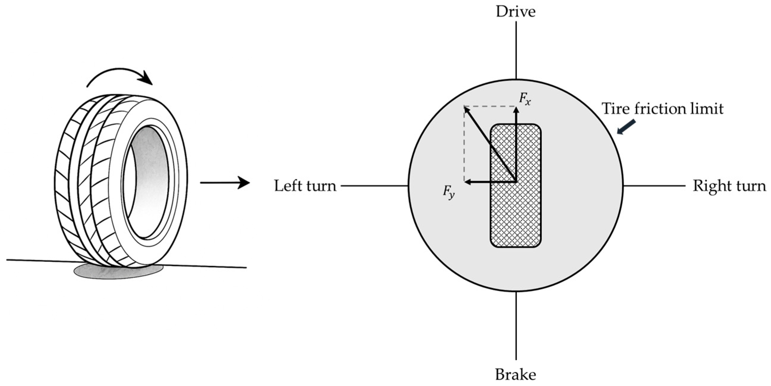
The combined longitudinal and lateral tire forces must satisfy the friction constraint to ensure that the tire operates within its physical limits (as shown in
Figure 4), thereby preventing loss of adhesion that could lead to slipping or loss of control. Specifically, the longitudinal force
and lateral force
are constrained by the inequality:
where
is the friction coefficient between the tire and the road surface,
is the vehicle mass,
is the acceleration due to gravity, and
is an empirical coefficient used to adjust the friction limit,
. Ignoring the lateral road slope, the lateral tire force
can be expressed as:
When the lateral tire force reaches the ground adhesion limit, the vehicle attains its maximum driving speed, and the longitudinal force is zero. By combining Equations (8) and (9), the maximum safe vehicle speed
can be determined.
Since the autonomous vehicle maintains a certain initial speed before entering the trajectory, the maximum safe speed calculated solely based on curvature does not directly represent the actual speed at each point. When the maximum speed derived from curvature exceeds the preset initial speed
, the desired safety vehicle speed is set to this initial speed to ensure reasonable and safe velocity profiles.
To systematically enhance both driving comfort and dynamic feasibility in speed profile planning, this paper employs a combination of forward and backward recursive methods to determine the desired speed at each reference point along road segments with varying curvature. Specifically, the forward recursion is formulated as follows Equation (12), ensuring that the vehicle speed at each sampled point does not exceed the maximum safe speed
derived from physical constraints such as curvature and tire-road friction, while also preventing excessive acceleration that could compromise comfort. Subsequently, a backward recursion is applied from the terminal point toward the starting point, as shown in Equation (13). This joint constraint imposed by the forward and backward recursions effectively suppresses undesirable phenomena such as abrupt acceleration and deceleration, which negatively impact ride comfort. As a result, the proposed approach enables a dynamically smooth transition of autonomous vehicle speed, providing an improved speed reference for downstream vehicle controllers and enhancing both driving comfort and operational safety.
where
denotes the reference speed at the point
,
is the maximum safe speed at the point
calculated based on physical constraints such as curvature,
represents the maximum allowable acceleration of the vehicle (its value is greater than 0),
is the maximum allowable deceleration (its value is less than 0), and
denotes the distance between adjacent reference points.
The vehicle speed control module is designed to achieve high-precision, real-time tracking of the reference speed profile generated by the planning module, thereby enabling effective adjustment and optimization of the vehicle’s dynamic response. Specifically, the controller continuously monitors the instantaneous deviation between the actual vehicle speed and the target reference speed, and computes the speed error
in real time. This error signal serves as the primary input to the PID controller, which combines the proportional, integral, and derivative components of the error to generate the appropriate control command—namely, the required longitudinal driving or braking torque, as shown in Equation (14). This torque is then applied to the vehicle dynamics model, realizing precise closed-loop control of speed and effectively suppressing speed deviations caused by external disturbances, model uncertainties, or changing road conditions. Through this closed-loop control strategy, the system enhances the smoothness of vehicle operation, the responsiveness to speed commands, and overall driving safety.
In this equation, denotes the driving torque of the vehicle, is the proportional gain, is the integral gain, and is the derivative gain.
3.2. Trajectory Tracking Controller
To achieve precise, rapid and stable tracking of preset trajectories by vehicles, this section designs a trajectory tracking controller based on MPC. This section constructs the prediction model, including linearizing and discretizing the nonlinear vehicle dynamics model and constructing it into an incremental form state space equation suitable for MPC solution. Meanwhile, the formulation of the objective function and constraint conditions is elaborated in detail to achieve the solution of the control problem.
3.2.1. Construction of the Predictive Model
MPC is an advanced control approach based on system dynamic models and optimization theory. The core concept of MPC is to use the current system state and known reference trajectory at each sampling instant to predict the system behavior over a finite future time horizon. The previously established vehicle dynamics model is nonlinear, which results in high computational complexity and poor real-time performance during state prediction. To improve computational efficiency and facilitate the application of the vehicle dynamics model within a discrete MPC controller, this study employs the midpoint Euler discretization method to obtain the discrete-time state-space representation:
where
represents the control vector of the vehicle at time
,
represents the state vector of the vehicle at time
,
denotes the sampling period.
,
.
In order to express the system’s prediction equations in terms of the incremental control input, a new state variable
is introduced in this study. By introducing the control increment
, the state
can be expressed like Equation (16). Using the variables defined above, the linear time-varying predictive model can be expressed as Equation (17).
where
With the predictive model established above and the current state at time , the outputs over the prediction horizon at time steps , , , , , can be derived as follows, In the equation, denotes the prediction horizon, and denotes the control horizon.
Following the standard MPC formulation, the system’s future predicted outputs are expressed as a direct function of the current state
and the subsequent sequence of control increments
,
,
,
. To compactly represent these predictions, the outputs over the prediction horizon are stacked into a single vector
. Correspondingly, the control increments are arranged into a vector
. Therefore, the predicted output can be succinctly expressed as:
where
3.2.2. Formulation of the Objective Function and Constraints
To achieve rapid and precise tracking of a predefined trajectory while ensuring smoothness and stability in the control process, a quadratic cost function is designed. This objective function comprehensively balances tracking accuracy, control stability, and solution robustness. Its explicit form is given as follows:
The first term of is designed to minimize the trajectory tracking error of the vehicle states over the entire prediction horizon. At each step, the output error is weighted and accumulated using the weighted 2-norm , where is a positive definite weighting matrix reflecting the relative importance of each output component in the overall performance metric. Furthermore, to ensure system performance and stability at the end of the prediction horizon, a terminal weighting term is introduced into the cost function, where is the terminal output weighting matrix. This term emphasizes that the system output at the end of the prediction horizon should be as close as possible to the reference trajectory, contributing to ensure the closed-loop stability of the rolling time-domain control and preventing slow convergence or terminal state drift.
The penalizes the control input increments , which represent the changes in control inputs from the current time to each step within the prediction horizon. In this study, corresponds to the variation in the front wheel steering angle. The control increments are weighted and accumulated via the weighted 2-norm , where is the input weighting matrix. This term serves to constrain the smoothness of control commands, preventing abrupt input changes and thereby enhancing system robustness. A slack variable is incorporated along with a penalty term , where is a non-negative penalty weight. This design balances constraint feasibility and control performance, ensuring that the optimization problem remains solvable under all circumstances.
To simultaneously achieve high-precision trajectory tracking and smooth control commands during vehicle operation, and to effectively prevent the degradation of ride comfort caused by large fluctuations in control inputs, it is essential to impose appropriate and stringent constraints on the control variables, control increments, and output variables within the vehicle control system. These constraints not only ensure the safe and stable operation of the system but also enhance overall ride quality and control performance. The specific constraint design is as follows:
The first constraint limits the range of the front wheel steering angle, the control input, at each prediction step, ensuring it remains within the physical limits achievable by the vehicle’s steering actuator. The second constraint restricts the magnitude of control input increments between consecutive steps, preventing abrupt changes in the controller output, thereby maintaining vehicle handling stability and ride comfort. Additionally, this constraint helps enhance vehicle dynamic stability by avoiding loss of control caused by aggressive maneuvers. The third constraint imposes bounds on the system outputs, ensuring that the vehicle’s operating states remain within predefined limits, which improves the accuracy and precision of path tracking. The fourth constraint limits the magnitude of the slack variable, preventing performance degradation such as slow convergence and numerical instability during optimization.
To effectively solve the aforementioned optimization problem, it is necessary to reformulate it into a standard QP framework. In this process, the objective function and the associated constraints are uniformly expressed in canonical quadratic form. The quadratic cost function is explicitly represented in terms of the decision variables, while the constraints, which include input magnitude limits, input rate limits, output bounds, and slack variable restrictions, are systematically transformed into linear inequalities or equalities. Through this standardized reformulation, the optimization problem can be efficiently solved by numerical solvers with guaranteed convergence properties, thereby addressing large-scale constrained optimization tasks. Furthermore, this transformation facilitates the real-time implementation of the control algorithm and ensures that the unmanned delivery vehicle achieves robust and stable performance in complex trajectory tracking control tasks.
where
is the quadratic cost matrix,
represents the linear cost vector,
and
are the matrix and vector for the linear inequality constraints, respectively,
and
are the lower and upper bounds for the optimization variables. To reformulate Equation (21) into the standard objective function form of a QP problem, each term in the equation can be transformed as follows:
where
By substituting the aforementioned Equation (18) into this expression, can obtain Equation (25).
Through the above formula transformations, the objective function can be expressed as the following equation:
Based on this, it can be formulated in the standard form of a quadratic programming problem as follows:
where
,
and
denote appropriate identity and zero matrices, respectively.
By solving the aforementioned quadratic programming problem, a series of optimal variables is generated within each cycle, yielding a control increment sequence:
The first element in the sequence serves as the actual control increment. This is used to obtain the control input applied to the system, the control vector can be expressed as Equation (30). By repeating the above process, and based on the rolling optimization feature, the vehicle can achieve the tracking of the reference trajectory.
4. Simulation
To validate the effectiveness of the proposed control method, this section conducts simulation experiments on a co-simulation platform based on MATLAB/Simulink (R 2024 b) and Carsim (2021.0). To systematically evaluate the adaptability and robustness of the proposed autonomous vehicle control strategy under complex conditions, this study designs a comprehensive simulation framework that covers typical path tracking tasks. The simulations are conducted under two standard scenarios: single lane change (SLC) and double lane change (DLC), and are performed on road surfaces with high ( = 0.85 and low ( = 0.4) adhesion coefficients. This approach is intended to thoroughly reveal the dynamic performance and control limits of the system under both nominal and extreme conditions.
During the simulation process, key dynamic response indicators are collected and analyzed, including the vehicle’s longitudinal and lateral positions, front wheel steering angle, yaw angle, and lateral error. By comparing the tracking accuracy and stability under different conditions, the effectiveness and engineering applicability of the proposed method are comprehensively validated. Controller 1 is the integrated controller proposed in this paper, while controller 2 employs an independent model predictive control algorithm for lateral control; the vehicle speed remains at the initial value (36 km/h) when entering the trajectory and tracks the trajectory at this constant speed.
In this study, the C-Class Hatchback model from the Carsim software was selected as the simulation object, and the tire model chosen was 215/55 R17. In order to fully reflect the differences in different controllers in the simulation scenario, controllers 1 and 2 adopt the same parameter settings in the MPC. The vehicle dynamic parameters and the controller parameter settings used in the simulation are listed in
Table 1.
4.1. Scenario 1: Single Lane Change
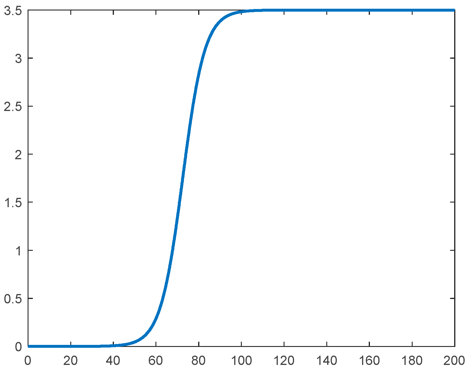
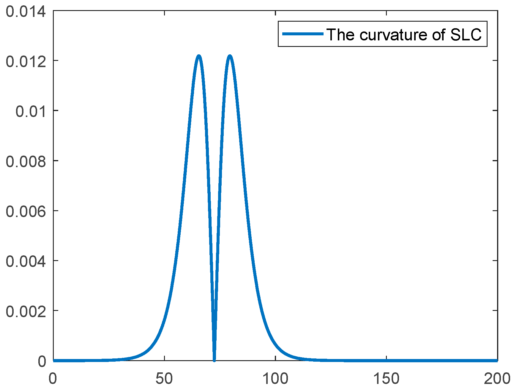
The SLC scenario, a typical test case in vehicle motion control research, features distinct stage-wise variations in path curvature. It effectively simulates complex driving situations such as obstacle avoidance and emergency lane changes encountered by autonomous vehicles during real-world operation. The expression of the lateral position of this road is shown in Equation (31). The standard reference trajectory for this scenario is shown in
Figure 5, with the corresponding curvature variations illustrated in
Figure 6. The complexity of the road characteristics in this scenario imposes stringent requirements on the control strategy’s tracking accuracy, system stability, and adaptability to dynamic conditions. Therefore, the SLC scenario serves as a critical benchmark for validating the effectiveness of autonomous vehicle motion control strategies under complex curvature variations.
4.1.1. High Adhesion Test of SLC
The SLC test was conducted for an unmanned delivery vehicle traveling at an initial speed of 36 km/h on a road with a friction coefficient of 0.85. A detailed comparison was performed between the conventional fixed-speed control strategy and the proposed integrated control strategy across multiple performance metrics.
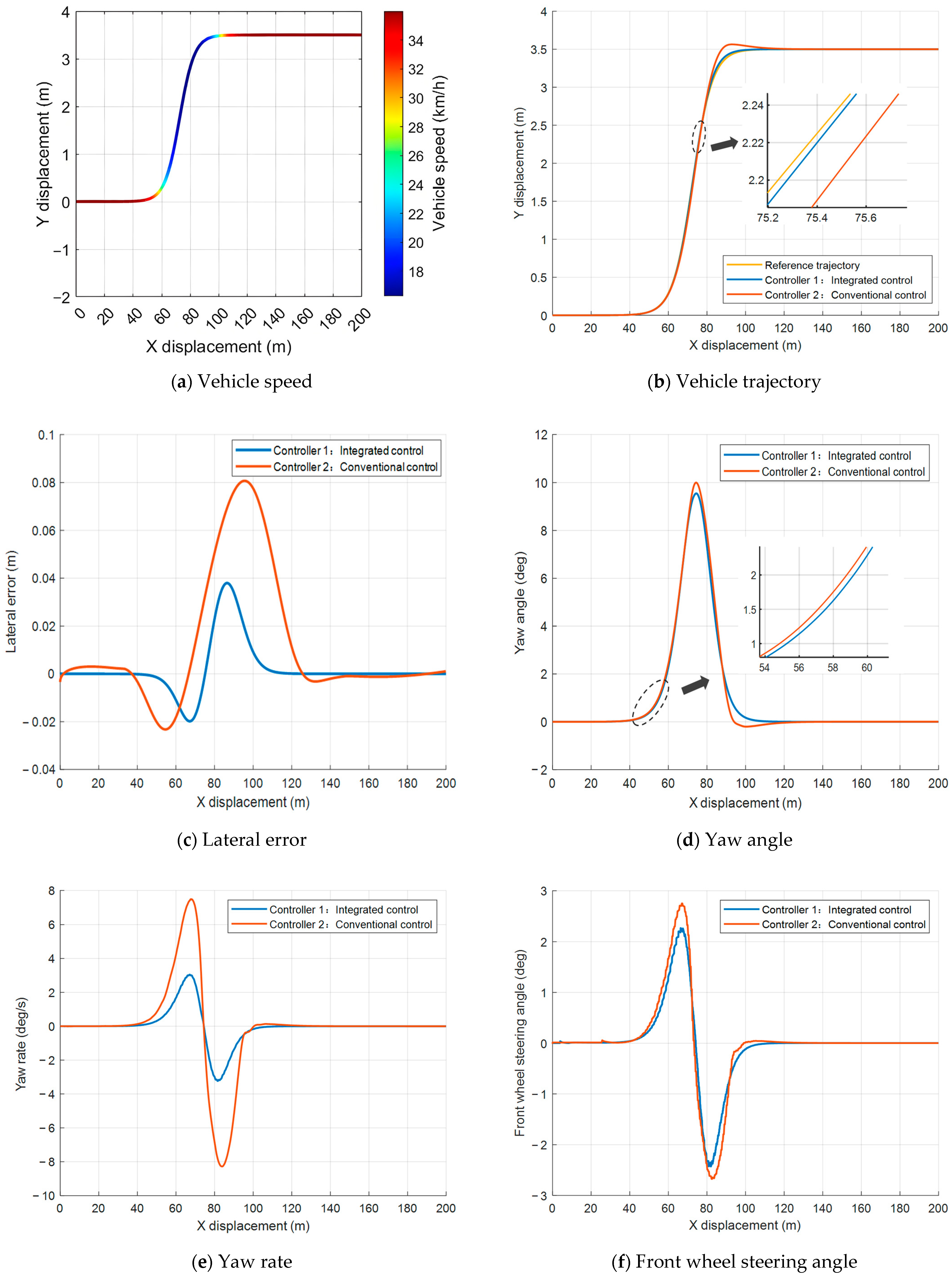
To evaluate the performance of the proposed integrated control strategy under normal adhesion, this study conducted a comparative analysis with a conventional controller in this scenario, as shown in
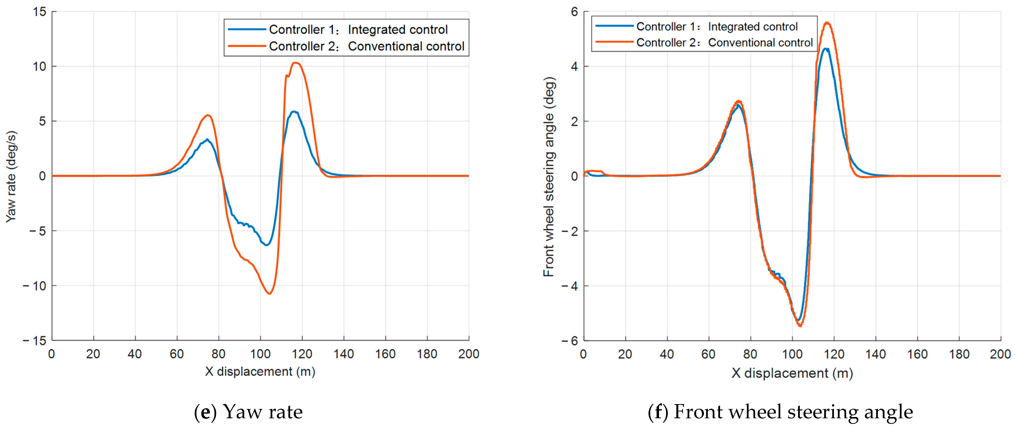
Figure 7. The simulation results demonstrate that the proposed controller exhibits significant superiority in vehicle attitude response, lateral tracking accuracy, and control smoothness.
Figure 7a intuitively presents the dynamic variation in vehicle speed during the maneuver. The overall trajectory tracking performance (
Figure 7b) clearly highlights the difference between the two controllers in sections with severe path curvature changes (lateral position 60–90 m). The conventional controller exhibits notable overshoot after steering maneuvers, causing the vehicle to deviate laterally from the reference path, with a maximum lateral error reaching 0.08 m. In contrast, the proposed integrated controller closely follows the target path with minimal overshoot, reducing the maximum lateral error to 0.04 m, which represents an improvement of nearly 40% and thus validates its superior path tracking capability (
Figure 7c).
This improvement in tracking accuracy benefits from the controller’s enhanced regulation of vehicle dynamic response. From the heading angle response (
Figure 7d), it can be observed that, during sharp turns, the conventional controller produces a peak heading angle of approximately 10 deg, whereas the integrated controller achieves a lower peak with a smoother response curve. The lateral yaw rate trend (
Figure 7e) further corroborates this: the conventional controller causes large fluctuations of approximately
8 deg/s, while the integrated controller restricts the peak yaw rate within
3.1 deg/s, effectively suppressing violent body oscillations and enhancing lateral stability.
The front wheel steering angle output (
Figure 7f) also reflects this smooth and efficient control characteristic. The integrated controller’s steering input peak is slightly lower than that of the conventional controller, and its curve is smoother, avoiding unnecessary and large steering corrections. This not only improves stationarity but also helps reduce the risk of tire saturation and sideslip.
4.1.2. Low Adhesion Test of SLC
Low road adhesion has a significant impact on the safe operation of unmanned delivery vehicles. After validating the control performance of the proposed strategy under high adhesion in SLC scenario, this section further shifts the test environment to low adhesion road conditions to evaluate the robustness and stability of the proposed control strategy under degraded adhesion.
The road adhesion coefficient is set to
0.4, and simulation tests are conducted for the SLC. The results are presented in
Figure 8.
Figure 8a intuitively shows the integrated controller’s dynamic speed regulation ability during the test, demonstrating strong adaptability and smooth control. From the trajectory tracking results (
Figure 8b), the conventional controller exhibits significant overshoot in the main lane change segment, with the vehicle’s maximum lateral displacement substantially exceeding the reference trajectory, resulting in reduced tracking accuracy. In contrast, the integrated controller effectively suppresses the overshoot and closely aligns with the reference trajectory, demonstrating stronger trajectory convergence under low adhesion conditions. Regarding lateral error metrics (
Figure 8c), the conventional controller’s maximum lateral error reaches 0.113 m and shows considerable deviation in trajectory transition sections. The integrated controller maintains lateral errors consistently below 0.04 m, demonstrating superior tracking accuracy and robustness.
The heading angle response (
Figure 8d) shows that the conventional controller experiences large peaks accompanied by noticeable negative oscillations in curvature change regions, indicating significant oscillations during directional corrections. The integrated controller not only achieves lower peak values but also exhibits a smoother response curve, enabling more stable heading control and reducing the risk of instability caused by abrupt corrections under extreme conditions. The comparison of yaw rate (
Figure 8e) further confirms this observation: the conventional controller generates intense fluctuations with a peak yaw rate of up to 6.138 deg/s in high curvature sections, which may induce vehicle instability. In contrast, the integrated controller limits the peak yaw rate to within
2.528 deg/s, mitigating the dynamic response and enhancing the vehicle’s overall lateral stability. Finally, the front wheel steering angle response (
Figure 8f) indicates that the conventional controller’s steering input varies widely between
3.9 and 3.57 deg, with considerable fluctuations. The integrated controller’s maximum steering angle is approximately 2.516 deg, and the response curve is smoother, effectively preventing tire saturation and lateral instability, while also improving ride comfort.
In summary, the proposed integrated control strategy in this paper enables the controller to dynamically adjust the speed based on the curvature of the road and the adhesion coefficient, allowing the vehicle to track the trajectory at a safe speed and achieving higher trajectory tracking accuracy.
4.2. Scenario 2: Double Lane Change
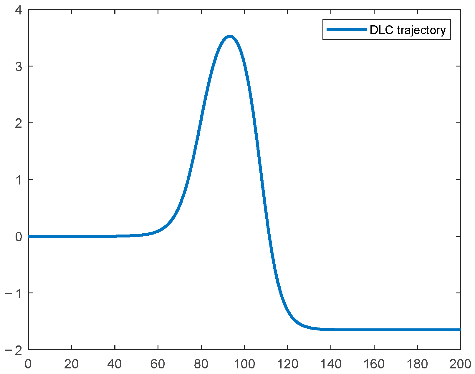
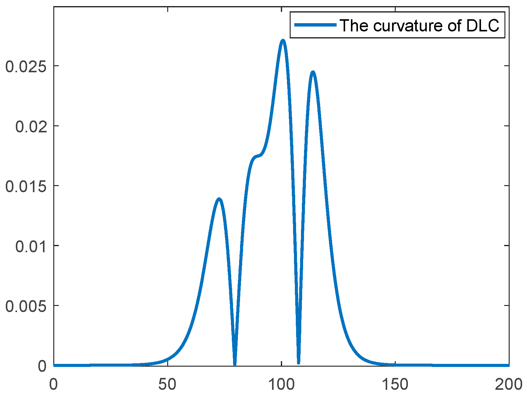
This section further selects the DLC scenario as the test case to conduct more challenging motion control simulations for the unmanned delivery vehicle. Compared to the SLC, DLC scenario provides a more comprehensive assessment of the vehicle’s motion control capabilities when confronted with complex paths and continuous lane change tasks. It imposes higher demands on trajectory tracking accuracy, vehicle attitude stability, and real-time control responsiveness, while more closely reflecting typical driving conditions that unmanned delivery vehicles may encounter on urban roads. The expression of the lateral position of this road is shown in Equation (32).
To ensure the scientific validity and representativeness of the simulation scenarios,
Figure 9 and
Figure 10 present the reference trajectory of the DLC road and the corresponding curvature variations, respectively. These figures visually illustrate the complexity of the path geometry and the dynamic distribution of curvature under the DLC. Based on this, comparative tests between the conventional controller and the integrated controller were conducted under both high and low adhesion coefficients (
0.85 and
0.4) to systematically evaluate the adaptability and robustness of the proposed control strategy in complex road environments and extreme conditions.
4.2.1. High Adhesion Test of DLC
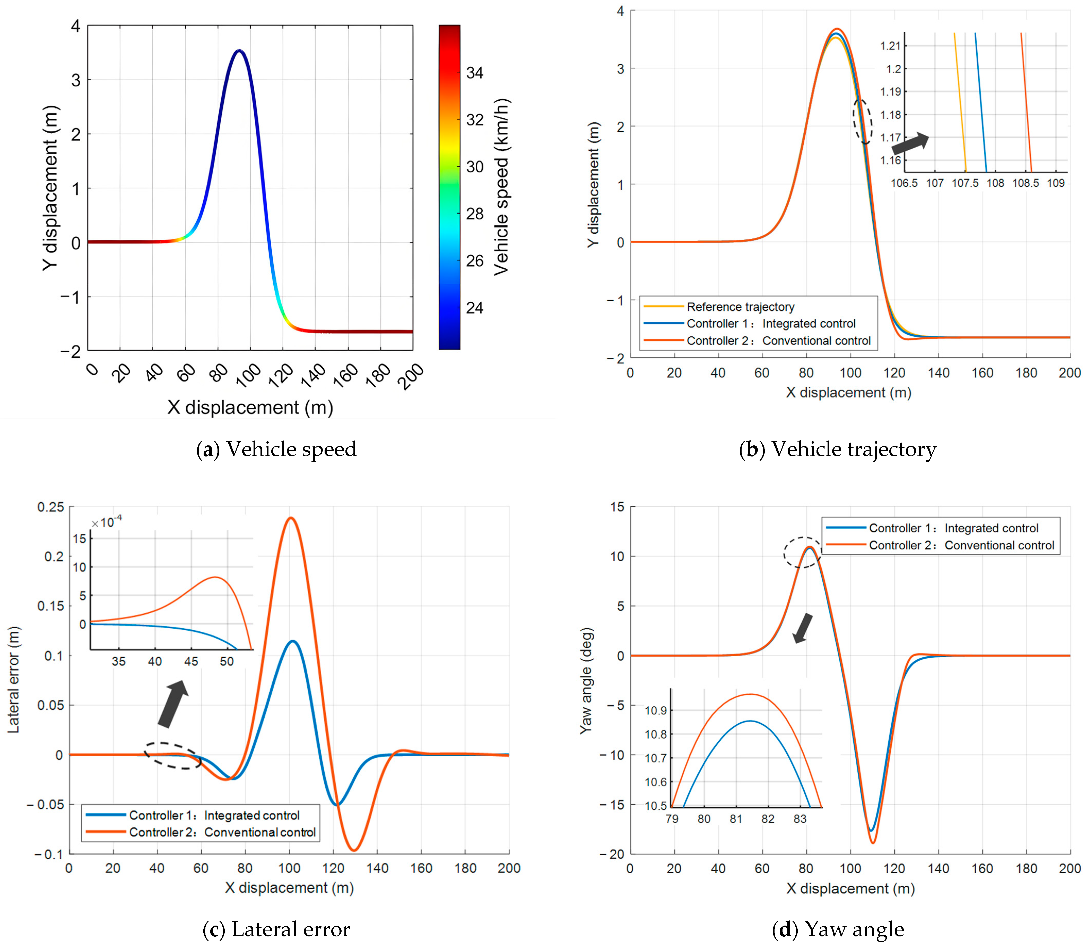
To thoroughly evaluate the motion control performance of the proposed integrated controller under complex conditions, this study conducted DLC simulations under high adhesion conditions ( 0.85), comparing the integrated controller with a conventional controller in terms of path tracking, vehicle attitude response, and control smoothness. The main findings are as follows.
Figure 11a illustrates the integrated controller’s adaptability to the unique speed demands of the DLC scenario.
Figure 11b shows the differences in tracking performance between the two controllers. The conventional controller exhibits greater deviation of the actual vehicle trajectory from the reference path in road segments with significant curvature changes, whereas the integrated controller effectively suppresses overshoot and oscillations, maintaining close alignment with the reference trajectory. This demonstrates the integrated controller’s superior tracking accuracy in sections with large curvature variations. The lateral error shown in
Figure 11c, the conventional controller produces a maximum lateral error exceeding 0.24 m with large fluctuations in the lane change segment, while the integrated controller limits the maximum lateral error to 0.12 m with reduced overall variation. These results indicate that the integrated controller enhances path tracking robustness and accuracy under complex conditions.
Figure 11d,e present the vehicle’s heading angle and yaw rate responses, respectively. Under conventional control, the heading angle exhibits large positive and negative peaks during the double lane changes, with the maximum negative peak approaching
19 deg. In contrast, the integrated controller reduces these peak values and smooths the heading angle variation, contributing to improved vehicle stability and controllability under complex scenarios.
Figure 11f depicts the front wheel steering angle variations. The conventional controller requires larger steering angle changes during the DLC, which may exacerbate tire loading and lead to sideslip saturation. The integrated controller effectively limits peak steering angles, reducing the maximum value by 17.86% compared to the conventional controller, and provides smoother steering dynamics, enhancing vehicle handling stability and reducing risks associated with extreme maneuvers.
4.2.2. Low Adhesion Test of DLC
During continuous lane change maneuvers in the DLC scenario, unmanned delivery vehicles are more prone to slipping, instability, and even complete deviation from the target trajectory. The low-adhesion DLC condition poses more stringent challenges to the robustness of the control system and its capability to maintain extreme attitude control. Building upon the performance validation under high adhesion conditions, this section shifts the simulation environment to a low adhesion road surface ( 0.4) to systematically test and analyze the proposed control strategy’s ability to suppress loss of control and ensure safety under extreme conditions. This aims to reveal the true dynamic performance of different control methods in high-risk scenarios.
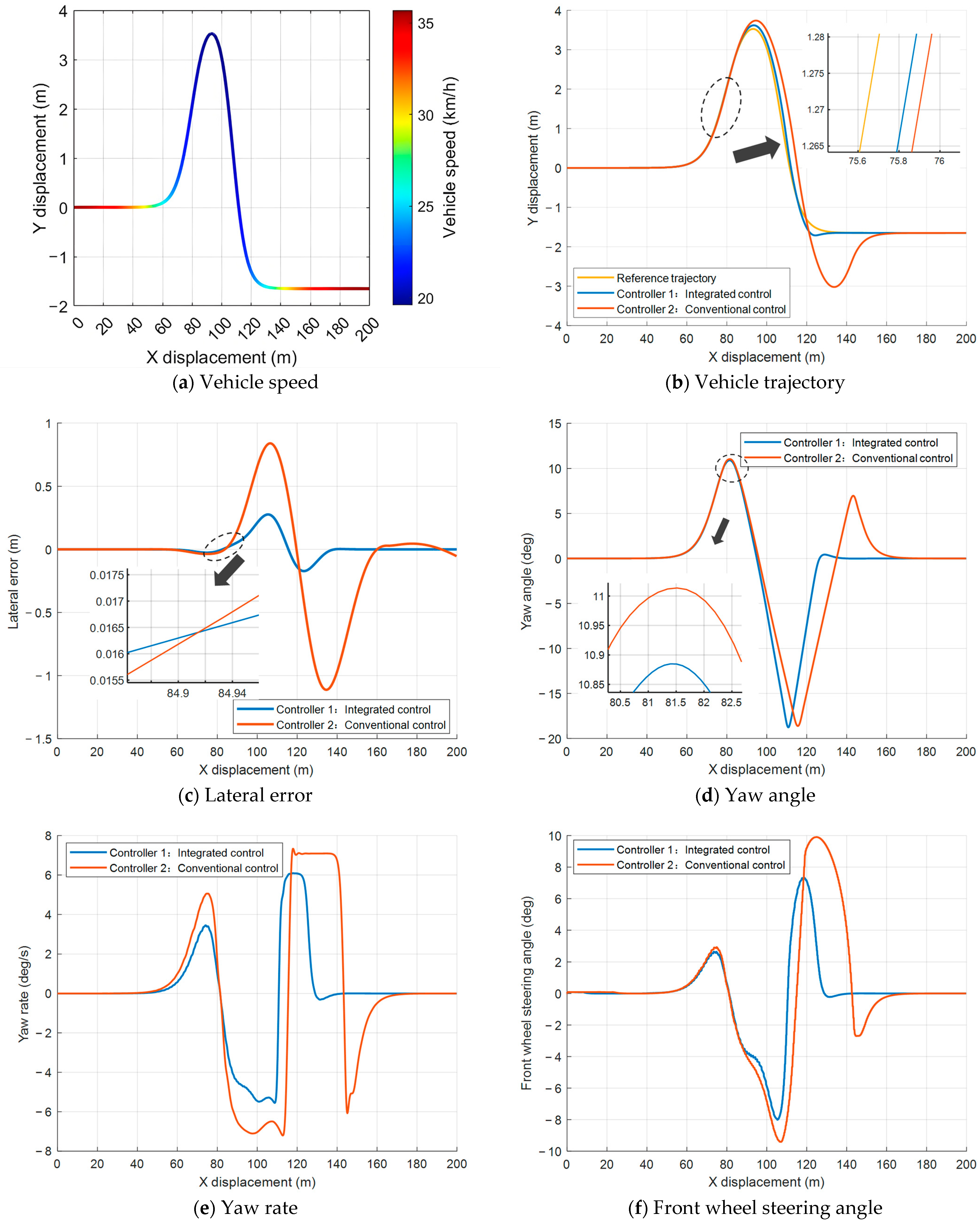
Figure 12a illustrates the dynamic speed regulation of the vehicle under low adhesion conditions during the scenario. It can be observed that the vehicle speed is effectively reduced to approximately 16 km/h in sections with significant curvature changes to adapt to the complex road conditions and ensure driving safety. Regarding trajectory tracking performance,
Figure 12b,c present the tracking results and corresponding lateral position errors, respectively. The conventional controller exhibits noticeable trajectory deviation after the second lane change, with a maximum lateral error reaching 1.09 m and increased overall error fluctuations. In contrast, the proposed integrated controller effectively suppresses overshoot, maintaining the vehicle trajectory closely aligned with the reference path. The maximum lateral error is approximately 0.3 m, with rapid error convergence to zero, demonstrating superior robustness and control accuracy.
The vehicle’s heading angle response and yaw rate variations are shown in
Figure 12d,e, respectively. The conventional controller generates large positive and negative peaks during the DLC, indicating significant oscillations and instability. The integrated controller substantially reduces the peak amplitude and fluctuations of the heading angle, resulting in smoother responses that enhance vehicle attitude stability under extreme conditions. Notably, during the second lane change, the conventional controller’s peak yaw rate reaches 7.3 deg/s and persists for an extended duration, increasing the risk of instability. The integrated controller successfully limits the peak yaw rate and quickly restores dynamic stability, reducing the yaw rate variation by approximately 19.92% compared to the conventional controller and improving lateral stability under low adhesion.
Figure 12f depicts the front wheel steering angle input. The integrated controller reduces the peak steering angle by 19.15% compared to the conventional controller and provides smoother steering angle transitions, effectively mitigating control risks in extreme conditions and enhancing driving safety and handling stability.
To visually demonstrate the differences in the simulation results of the above four categories, the root mean square of the lateral error and the overall change in the front wheel rotation angle during the trajectory tracking process were selected as indicators to draw
Table 2. This table can quantitatively reflect that the control strategy proposed in this paper has certain advantages in terms of trajectory tracking accuracy, control smoothness and stability.
5. Discussion
The proposed control strategy for the unmanned delivery vehicle demonstrates excellent performance across various road geometries and adhesion conditions. Compared to traditional fixed-speed control methods, the integrated framework presented in this study achieves more precise and stable trajectory tracking. Under high-adhesion conditions, the controller ensures high tracking accuracy and lateral stability during complex single- and double-lane change maneuvers. Under low-adhesion conditions, it suppresses tire side-slip and trajectory overshoot, effectively reducing the risk of instability. These results confirm that the integrated approach, combining adaptive speed regulation with predictive path control, can guarantee the safety and reliability of unmanned delivery vehicles in complex operating scenarios.
The proposed control strategy for the unmanned delivery vehicle demonstrates excellent performance across various road geometries and adhesion conditions. Com-pared to traditional fixed-speed control methods, the integrated framework presented in this study achieves more precise and stable trajectory tracking. Under high-adhesion conditions, the controller ensures high tracking accuracy and lateral stability during complex single- and double-lane change maneuvers. Under low-adhesion conditions, it significantly suppresses tire side-slip and trajectory overshoot, effectively reducing the risk of instability. These results confirm that the integrated approach, combining adaptive speed regulation with predictive path control, can guarantee the safety and reliability of unmanned delivery vehicles in complex operating scenarios.
The speed controller, based on PID theory, incorporates road curvature and the adhesion coefficient into its speed regulation mechanism. This approach effectively prevents the tire force saturation issue caused by excessive speeds in traditional fixed-speed control methods. In real-world scenarios, this translates into a crucial safety enhancement. When an unmanned delivery vehicle encounters an unexpectedly low-grip surface (such as a puddle or icy surface) while turning, it can avoid sudden loss of control or skidding. The lateral path controller employs an MPC approach that includes both lateral position and heading angle errors in its optimization objective. It solves for the optimal front wheel steering angle under system constraints, thereby unifying trajectory tracking accuracy with vehicle stability. This integration has resulted in significantly smoother responses, which is not only crucial for enhancing vehicle stability, but also essential for ensuring the safety of goods, as well as potentially reducing mechanical wear and energy consumption.
Nevertheless, certain limitations of the present study should be acknowledged. Primarily, the findings are based on a co-simulation environment involving MATLAB/Simulink and Carsim, and thus lack verification from real-world vehicle testing. The controller proposed in this paper avoids the severe oscillations and potential instability risks encountered by the fixed-speed controller at high speeds by dynamically adjusting the speed. However, this strategy has increased the travel time of the vehicles. In the future, we will continue to study the collaborative optimization of factors such as vehicle speed maintenance, vehicle stability maintenance, and trajectory tracking accuracy.
Furthermore, the controller design assumes a relatively decoupled dynamic model. However, under extreme operating conditions (such as when the vehicle dynamics exhibit significantly stronger coupling), this assumption may not hold true. The scope of this study also does not cover the consideration of external disturbances (such as crosswinds or changes in vehicle load and controller robustness due to complex road conditions). Future research will focus on addressing these limitations through on-board experiments, developing strong-coupling dynamic models, and exploring intelligent control strategies to enhance the adaptability and engineering applicability of the controller.
6. Conclusions
This paper investigates the trajectory tracking control problem for unmanned delivery vehicles under complex road geometries and varying adhesion conditions. An integrated control framework is proposed and systematically validated under typical operating scenarios, including single- and double-lane change maneuvers on surfaces with both high and low adhesion. The results demonstrate that the proposed control strategy effectively enhances the vehicle’s trajectory tracking accuracy and operational stability, exhibiting strong robustness and significant potential for practical engineering applications. We have drawn the following conclusions.
This paper establishes a tracking error model based on vehicle dynamics, which integrates the lateral position error and heading angle error into a unified state-space representation. An integrated control framework that combines velocity control with lateral path tracking control is also proposed. The speed controller, based on PID theory, achieves adaptive speed regulation by considering road curvature and the road adhesion coefficient. The lateral controller employs a MPC approach to achieve optimal control of the front wheel steering angle by minimizing lateral position and heading angle deviations. This study first establishes a tracking error model based on vehicle dynamics, integrating the lateral position error and heading angle error into a unified state space representation. On this basis, an integrated control framework is proposed. Unlike traditional fixed-speed schemes that may fail due to tire force saturation in high curvature or low adhesion conditions, this paper does not have the lateral MPC passively deal with extreme bends or low-adhesion road surfaces alone. Instead, a PID speed controller is introduced, combined with road curvature and adhesion coefficient for forward-looking and adaptive speed regulation, ensuring that the vehicle is within the safety margin of the friction limit before entering the bend. Subsequently, the lateral MPC, under the constraints of actuators and friction, optimizes the steering angle of the front wheels by minimizing the lateral deviation and heading deviation, achieving high-precision path tracking and lateral stability.
Simulation tests are conducted under typical single lane change and double lane change scenarios, with both high and low adhesion coefficients. The proposed control strategy is systematically compared with conventional fixed-speed control methods under different conditions. Co-simulation results from MATLAB/Simulink and Carsim demonstrate that the proposed control strategy not only achieves excellent path tracking performance and stability under high adhesion conditions but also effectively suppresses risks such as tire sideslip and trajectory overshoot in extreme low adhesion environments, substantially improving the driving safety and control reliability of unmanned delivery vehicles.
This work provides a theoretical foundation and practical reference for the design and engineering application of motion control systems for unmanned delivery vehicles. Future research can further incorporate real-world road tests and multi-source disturbances, such as crosswinds and payload variations, to validate robustness and promote intelligent and large-scale deployment of unmanned delivery vehicles in complex urban environments.
This research provides a theoretical basis and practical reference for the design and engineering application of the motion control system for unmanned delivery vehicles. Future studies can further incorporate actual road tests and the consideration of multiple interference factors, such as wind side and road slope-induced load changes, as well as verify the robustness of the controller in these complex environments, and promote the intelligence and large-scale deployment of unmanned delivery vehicles in complex urban environments.

