Abstract
The starting material for this research was a metal–ceramic nanocomposite containing nanocrystalline iron with an average nanocrystallite size equal to 23 nm (based on X-Ray Diffraction; a specific surface area of 9 m2/g by the BET method) and a nanocrystallite size distribution standard deviation σ = 15 nm, promoted with hardly reducible oxides (Al2O3, CaO, K2O in total, max. 10 wt%), obtained by melting magnetite with promoter oxides at 1600 °C and reducing the resulting alloy with hydrogen at 500 °C. This material was then oxidized in a controlled manner with water vapor at 425 or 500 °C to achieve different oxidation degrees. Metallic iron remaining in the samples after the oxidizing step was removed by two-stage acid etching. Promoters introduced into the melt ensured the stability of the nanocomposite structure at elevated temperatures. After etching, the iron oxide was reduced with hydrogen at 375 or 500 °C. A series of nanocrystalline iron samples with different nanocrystallite sizes (in the range from 18 to 35 nm; specific surface areas decreased from 32 to 16 m2/g with increasing nanocrystallite size) and a narrowed nanocrystallite size distribution standard deviation σ = 3–5 nm was synthesized, which was then tested in the process of nitriding (at 375 and 500 °C), carburizing (400–550 °C), and oxidation (at 425 and 500 °C). The progress and rate of these reactions were measured in a differential tubular reactor with thermogravimetric measurement of mass changes in the solid sample and catharometric measurement of hydrogen concentration in the gas phase. The scalability of the proposed method was also investigated by conducting measurements on 1, 10, and 100 g samples. The effect of nanocrystallite size on the chemical properties of the tested samples was observed. The nanocomposite samples containing the smallest iron nanocrystallite sizes were found to be the most active in the nitriding reaction and catalytic decomposition of ammonia. All the tested modified samples were at least several times more active in the decomposition of ammonia than the unmodified sample. The practical effect of our work is the presentation and use of a new, more precise method for obtaining nanocrystallites of specific sizes.
1. Introduction
With the development of science and technology, i.e., the development of new techniques and research devices, the existence of nanomaterials became known decades ago. Today, we no longer have any doubt that these materials, often differing only in the degree of grain refinement (down to the nanoscale), exhibit significantly different physical [1,2,3], chemical [4,5,6], thermodynamic [7,8,9], and other properties compared to their coarse-grained counterparts, as it was earlier predicted with numerical modeling [10,11,12,13,14,15]. Moreover, it turns out that the properties of nanomaterials with different particle sizes can also differ significantly [16,17,18,19,20,21,22,23,24,25,26,27,28]. At the current stage of nanotechnology development, obtaining various nanomaterials generally poses no major problem. However, a difficulty that has not yet been fully overcome concerns obtaining nanoparticles with specific, precisely selected sizes. The next step is to study the properties of such specified fractions of nanomaterials, rather than defining these properties as merely averaged across a statistical set of nanoparticles with a broad size distribution.
Therefore, methods for synthesizing nanomaterials with precisely defined sizes are sought [29,30,31,32]. One such method is the chemical method presented in the patent description [33]. It is based on a model of reactions in the adsorption region [34], which was developed as a result of studies on the nitriding [35,36,37], carburizing [38,39,40,41,42], and oxidation [43] reactions of nanocrystalline metals (primarily iron, but also nickel and cobalt) [44,45,46]. According to this model, nanocrystallites undergo a phase transformation from substrate to product throughout their entire volume and in order of their size, from smallest to largest. Then, at different degrees of conversion, a stable system is obtained, consisting of two different crystallographic phases with different nanocrystallite sizes. One of the phases (usually the metallic phase) is then selectively etched with acid. This produces a nanomaterial with a narrowed nanocrystallite distribution. It is therefore possible to finally study single fractions of nanocrystallites, but due to the lack of addition of structure-forming promoters during the synthesis of nanomaterials using this first-generation method, the materials are stable only at low temperatures (around room temperature) [47].
In the second-generation method for fractionating nanocrystallites, as presented in [2], structure-forming promoters (Al2O3, CaO) were added at the first stage of synthesis, i.e., during the melting of magnetite with promoters (at a temperature of approximately 1600 °C). Although these additives are present in a small amount only (max. ca. several percent by weight), they ensure thermal stability to metallic iron nanocrystallites and develop their specific surface area [2,47]. Thus, due to this addition, the obtained metal–ceramic nanocomposites with specific metal nanocrystallite sizes were stable during further studies, even at temperatures exceeding 500 °C [47]. This method allows for the temperature range of research to be extended well beyond room temperature.
Other models of the nanocrystalline substance–gas phase reaction have also been proposed, both kinetic and equilibrium [44,45,48,49,50], which can aid in the development of new, more controllable methods for synthesizing such solid materials. Using these models, various chemical methods have also been developed to determine the actual size distribution of nanocrystallites under chemical reaction conditions [51,52].
During the examination of the nanocrystalline iron nitriding and iron nitride reduction processes, an explanation was given regarding the thermodynamic foundations of the hysteresis phenomenon [53,54,55] and the coexistence of two crystallographic phases next to each other (α-Fe(N) + γ’-Fe4N). It turned out that this is consistent with the Gibbs phase rule when the parameter relating to the size of the nanocrystallite as an additional degree of freedom is taken into account [55,56,57,58]. To be more specific, the minimum nitriding potentials in the processes of nanocrystalline iron nitriding and nitride reduction are directly proportional to the specific surface areas of nanocrystallites [59,60,61,62].
In particular, surface reactions, such as the catalytic decomposition of ammonia, sometimes combined with nitriding, are inherently related to the development of the specific surface area and, therefore, to the size of the solid particles participating in the reaction as catalysts [44,45,49,63].
Another technologically important process is the carburization of metals. It is crucial to understand the process, especially for operational reasons in some industrial catalytic hydrocarbon processing installations, to use nanocatalysts with optimal active nanoparticle sizes and fully control the process [64,65,66,67]. Another heterogeneous catalytic process involving the use of hydrocarbons is the production of carbon nanotubes. In recent years, carbon nanotube production has become exceptionally interesting, especially in relation to the structure of the obtained nanotubes as a function of the size of the catalyst nanoparticles used for their production, which is evidenced by a large number of articles on this topic [41,68,69,70,71,72,73,74,75,76].
The practical aim of the current work is to present a new method for separating a set of nanocrystallites into fractions of specific nanocrystallite sizes. Furthermore, the third-generation chemical method for separating nanocrystallites of specific sizes proposed in this work, which features a two-step etching step, allows for more extensive studies of individual nanocrystalline fractions, which were isolated with much greater precision than in previous generations of the chemical method. Interesting new results were obtained, and both the method and the underlying adsorption reaction model were validated and verified. It turns out that double etching results in a more precise narrowing of the nanocrystallite size range in the solid samples studied.
2. Experiment
The material used to prepare samples of a nanocrystalline composite containing iron nanocrystallites of different sizes is nanocrystalline iron doped with difficult-to-reduce promoter oxides, like Al2O3, CaO, and K2O. These additives are present in an amount of only several percent by weight, but they ensure thermal stability in iron nanocrystallites and develop their specific surface area [2,47]. In the first stage of nanomaterial synthesis, magnetite (Sigma-Aldrich, Saint Louis, MO, USA; containing iron oxides FexOY = 96.4%, MgO = 0.4%, Al2O3 = 0.13%, and CaO = 0.39%) was fused with Al2O3, CaO, and KNO3 (all purity grade: pure for analysis, Sigma Aldrich, Saint Louis, MO, USA) at a temperature of ca. 1600 °C for an hour [77]. Next, the obtained alloy of metal oxides was cooled and, after solidification, broken into smaller pieces and ultimately sieved to select grains with a size in the range of 1.0–1.2 mm. This fraction of grains was reduced with hydrogen polythermally to a temperature of 500 °C, under atmospheric pressure, and iron oxide was reduced to metallic iron. The promoter oxides were left unreacted and formed bridges made of a ceramic phase between iron nanocrystallites, stopping their sintering. After the reduction reaction, a nanocomposite composed of metallic iron and a ceramic phase was cooled in a nitrogen atmosphere and then passivated (in a mixture of 0.1% O2/N2 at a temperature of 50 °C, with continuous recording of changes in the mass of the solid sample—until the mass stabilizes; as a result, a thin passive layer of iron oxides was formed on the surface of the iron nanocrystallites in the amount of approximately 1.5% by weight) in order to avoid auto-ignition—in this way, a sample designated as S0 was obtained (pre-deduced form of a nanocomposite). The chemical composition of the nanocomposite samples was determined by the Inductively Coupled Plasma method (ICP-OES, spectrometer Perkin Elmer, type Optima 5300DV, Waltham, MA, USA): 3.5 wt% Al2O3, 3.0 wt% CaO, and 0.8 wt% K2O. The amount of oxygen after passivation was ca. 1.5 percent by mass; the rest of the sample was metallic iron.
X-ray Diffraction (XRD) measurements for all the prepared samples were conducted in an X’Pert Empyrean Philips X-ray diffractometer (Malvern Panalytical Ltd., Malvern, UK). The radiation source was a copper lamp (k = 0.1540 nm, accelerating voltage 35 kV, current 30 mA). An angle in the range of 10–110° [2θ], with a step of 0.05° and a count of 400 s per step, was applied. Based on the reflex from Fe(200), we determined the standard deviation for the conducted measurements at the level of 2.5%. Some studies were carried out using the Chemical Potential Proframmed Reaction method [67,68], implemented in the high-temperature XRK reaction chamber of a Philips X-ray diffractometer (XRK900, Anton Paar, Graz, Austria). Phase analysis of the samples was performed using the Rietveld method. Calculations were conducted based on crystallographic data contained in the identification card database ICDD PDF-4+ and by means of Philips X’Pert HighScore 3.0 software. For phase analysis, the cards of indices 04-003-3884 (iron), 04-007-1060 (magnetite), 00-035-0772 (iron carbide), and 04-004-9107 (γ’ iron nitride) were used. X-Ray Diffraction data for exemplary modified samples at different stages of synthesis are presented in Table S1 of the “Supplementary Materials”.
Nanocrystallite size distributions (NSDs) were determined by the method elaborated by Pielaszek [78,79]. Apart from X-ray measurement results, this method also uses an advanced mathematical mechanism, based on which the shape of the size distribution of nanocrystallites of a given phase is calculated, thanks to the analysis of the geometry of a specific diffraction reflection.
The adsorption method (using the Brunnauer–Emmet–Teller (BET) equation and automated apparatus AutoChem II 2920, Micromeritrics, Norcross, GA, USA) was applied to measure the specific surface areas (sample S0’s specific surface area was 9 m2/g).
The morphological properties of the obtained nanocrystalline iron samples were determined using transmission electron microscopy (TEM, Tecnai F30 with a field emission gun operating at 200 kV; Thermo Fisher Scientific, Waltham, MA, USA).
A diagram of the constructed research installation is shown in Figure 1 (nitriding and carburizing processes were carried out in the same installation after additional cylinders with ammonia (purity 99.999%; Air Liquide, Paris, France), methane (purity 99.995%; Messer Polska Sp. Z o.o., Chorzów, Polska) and ethene (purity 99.9%; Air Liquide, Paris, France) were connected to the system).
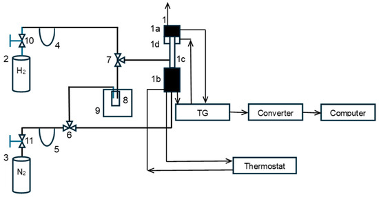
Figure 1.
Schematic diagram of the test installation: 1—spring thermobalance, 1a—temperature measurement system, 1b—mass measurement system, 1c—quartz reactor, 1d—reactor furnace, 2—hydrogen cylinder, 3—nitrogen cylinder, 4, 5—flow meter, 6, 7—three-way valve, 8—scrubber, 9—cryostat, and 10, 11—pressure reducing valves.
The essential elements of the installation were a thermogravimetric reactor (1) equipped with a hydrogen concentration meter (accuracy of 0.02 vol. %) in the gaseous reaction mixture for the continuous measurement of hydrogen concentration changes during chemical processes (designed and manufactured by means of our own supplies and certified by appropriate external authorities) [47,50]. In the reactor, test sample S0, weighing approximately 1.0 g, was placed in the form of a single layer of 1.0–1.2 mm grains in a platinum mesh basket suspended from a balance arm. The balance resolution was 0.05 mg. Hydrogen and nitrogen were drawn from cylinders (2) and (3), and the gas flow rates were regulated using electronic valves and flowmeters (4) and (5) from Brooks Instrument, Hatfield, PA, USA. After placing the test sample in the reactor, the system was flushed with nitrogen (15 dm3/h, purity 99.999%; Air Liquide, Paris, France) directed through a three-way valve (6), bypassing the scrubber (8). Then, after closing the nitrogen supply, hydrogen (9 dm3/h, purity 99.999%; Air Liquide, Paris, France) was introduced into the reactor through a three-way valve (7), and the polythermal reduction of the passive film was initiated within a temperature range of 20–500 °C. The sample was heated at 500 °C until its mass stabilized. During the reduction, a mass loss of approximately 30 mg/g was recorded. After the reduction, the reactor temperature was set at the desired level for the oxidation of nanocrystalline iron (425 °C or 500 °C), and hydrogen was removed from the reactor with nitrogen (without water vapor). Nitrogen was then fed into the reactor through a three-way valve (6) and a scrubber (8) with distilled water. The concentration of water vapor in the nitrogen fed to the reactor was controlled by setting the water temperature in the scrubber (18 °C, corresponding to 0.02 bar H2O in nitrogen at atmospheric pressure) located in a cryostat (9). After introducing a stream of nitrogen and water vapor into the reactor, the oxidation process began. To stop the oxidation process, after reaching the planned oxidation degree in the range of 0.1–0.7 g of oxygen added during the reaction by g of oxygen needed to completely oxidize the solid sample to magnetite, nitrogen was fed to the reactor, bypassing the water scrubber. The reactor was cooled to ambient temperature. The nitrogen flow was turned off, and the sample was left in the reactor for 12 h for passivation.
The next step was to select the optimal solvent for one of the crystallographic phases simultaneously present in the S0 samples after oxidation to specific conversion degrees. For this purpose, a series of tests was performed on 1 g samples using the following etching agents: nitric acid (65%, puriss; TH Geyer) and hydrochloric acid (min. 37%, pure for analysis; TH Geyer)—the etching time ranged from several to 24 h in both cases.
Based on the information obtained after this stage (details are given in the Discussion Section), a new generation of chemical methods for obtaining nanomaterials with specific nanocrystallite sizes was proposed, in which selective etching is performed in two stages. The proposed method is as follows:
- A nanomaterial with a broad nanocrystallite size distribution is subjected to a pre-reduction process with hydrogen at 500 °C. The size distribution of the nanocrystallites in the pre-reduced form of the nanomaterial should be determined, for example, using the XRD method. Based on the obtained results, the oxidation degrees to which the oxidation process should be carried out in the next step are determined to obtain a metal oxide with the required average nanocrystallite size.
- After the reduction process, the nanometal is oxidized at temperatures in the range of 400–500 °C with a gaseous oxidant, e.g., water vapor with a partial pressure of 0.02 bar in a nitrogen stream at atmospheric pressure. Oxidation is carried out within a range of oxidation degrees that ensures the entire chemical process occurs within the kinetic range of the reaction. For the samples currently tested, this range is α < 0.4 g/g.
- Samples oxidized to specific oxidation degrees are subjected to a two-stage selective etching process. In the first stage, a 0.5-molar hydrochloric acid solution is used to reduce the metallic phase content of the sample relative to the metal oxide. In the second stage, a 0.1-molar nitric acid solution is used to completely remove the metallic phase. Due to the oxidizing properties of nitric acid, the etching processes should last no longer than 5 h.
- After etching, samples containing primarily nanocrystalline metal oxide must be reduced with hydrogen at temperatures ranging from 375 to 500 °C. Before evacuation from the reactor, the nanomaterial must be passivated. The final result is a metallic nanomaterial with a defined average nanocrystallite size and a narrow size distribution.
At the end, the chemical composition of the solid samples was determined using the ICP method. It was found that after the two-stage etching process, the promoter content changed (compared to the S0 sample), which was as follows: 4.2 wt% Al2O3, 0.3 wt% CaO, and 0.2 wt% K2O.
The preparation procedure to obtain samples with a narrowed nanocrystallite size distribution is illustrated in Figure 2.
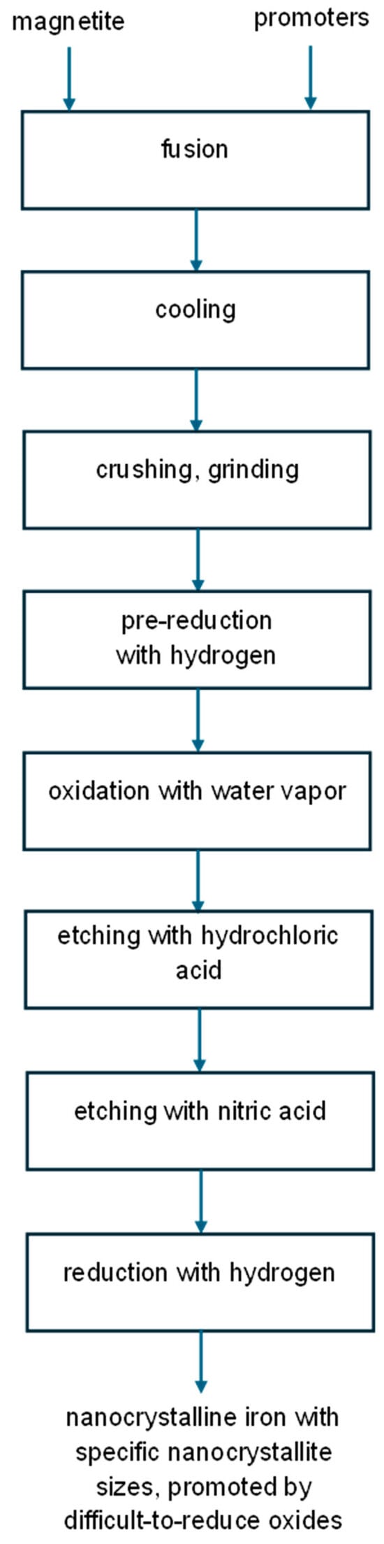
Figure 2.
Schematic diagram of the proposed chemical method for obtaining nanocrystalline substances with specific nanocrystallite sizes.
Samples of the nanomaterial S1–S7 with defined average iron nanocrystallite sizes and narrow size distributions, obtained according to the proposed procedure (approximately 0.2 g), were tested in the nitriding reaction with gaseous ammonia (12 dm3/(h g), at 375 °C) until a constant degree of iron nitriding was achieved. To verify sample stability, five nitriding–nitride reduction cycles were performed for each sample: the tested samples were stable under the conditions of the chemical process, and no differences in nitriding reaction rates were observed between individual cycles. For comparison, the nitriding reaction rate of sample S0 (i.e., unmodified) was measured under the same conditions. The synthesis of nanocrystalline iron nitrides was also undertaken at nitriding potential, P = pNH3/pH23/2 (pNH3—partial pressure of ammonia [Pa], pH2—partial pressure of hydrogen [Pa]), guaranteeing the formation of only one nitride phase, e.g., γ’. According to the results presented in paper [66], the samples should contain only γ’ iron nitride nanocrystallites when the nitriding process is carried out at 375 °C and at P = 0.02 Pa−1/2. After nitriding, the samples were examined by the XRD method to determine the phase composition and average nanocrystallite size.
To measure the catalytic ammonia decomposition reaction rate, rdec, the nitriding process was conducted at 500 °C, and hydrogen concentrations in the gas phase were recorded at steady state. Similar to the measurements conducted at 375 °C, nanocrystalline iron (approximately 0.2 g) was nitrided with ammonia (12 dm3/(h g); 100% at the reactor inlet) at 500 °C until a constant degree of iron nitriding was achieved. Based on the steady-state gas phase composition measurements, the activity of the tested samples in the catalytic ammonia decomposition reaction was determined. The ammonia decomposition reaction rate was calculated per gram of iron contained in the sample. For comparison, the ammonia decomposition rate was measured on a reference S0 sample under the same conditions. The nitrided samples were reduced with hydrogen and passivated, and their specific surface area was determined (based on the BET methodology, the surface area decreased from 32 to 16 m2/g with increasing nanocrystallite size).
The synthesis of iron carbides was carried out with ethene/hydrogen mixtures (ethene/hydrogen = 0.1; total gas flow rate of 30 dm3/(h g)) at temperatures of 400–550 °C. After carburizing, the samples were examined by the XRD method to determine the phase composition and average nanocrystallite size.
3. Results and Discussion
A precursor of a nanomaterial with a broad nanocrystallite size distribution after fusion is subjected to a pre-reduction process (with hydrogen at 500 °C). This leads to the reduction of the metal oxide, which constitutes the main phase of the sample (promoter oxides are not reduced under these conditions). Then, the size distribution of the nanocrystallites in the pre-reduced form of the nanomaterial is determined. The nanocrystalline composite (S0-type samples pre-reduced with hydrogen at 500 °C and passivated at approximately 50 °C; XRD examinations revealed the presence of only a metallic iron phase with an average nanocrystallite size of dm = 23 nm and a size distribution width of σ = 15 nm) was subjected to reduction processes in order to remove the passive layer (surface iron oxides) and then oxidized to a specific oxidation degree (α = 0.1, 0.2, 0.3, 0.4, 0.5, 0.6, or 0.7 g/g with respect to magnetite: samples S1–S7) with water vapor in a nitrogen stream—the nanocrystallites underwent a phase transformation to magnetite throughout their volume. Exemplary results of thermogravimetric measurements obtained at 500 °C are shown in Figure 3.
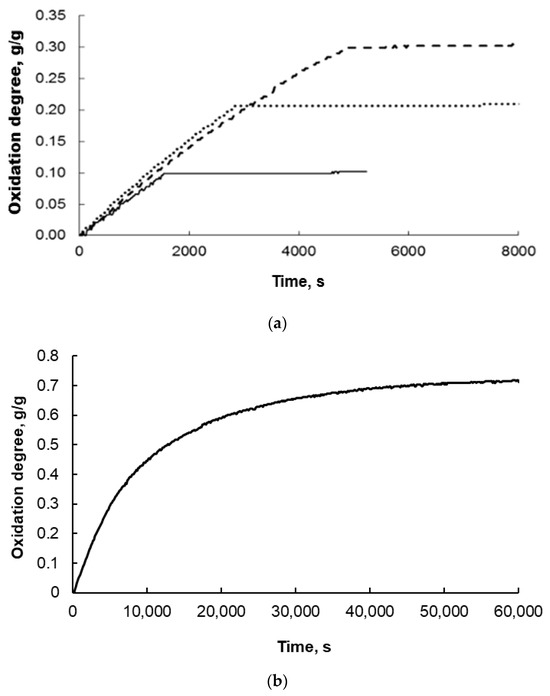
Figure 3.
Exemplary thermogravimetric measurement results obtained during the oxidation of nanocrystalline iron at 500 °C to oxidation degrees (a) α = 0.1, 0.2, and 0.3 g of oxygen added during the reaction by g of oxygen needed to completely oxidize the solid sample to magnetite and (b) 0.7 g/g.
The oxidation was carried out very slowly at low concentrations of water vapor in nitrogen to avoid uncontrolled oxidation or even combustion and to drive the reaction within the kinetic range of the reaction. Therefore, the figures above show that this reaction took thousands of seconds in the oxidation degree range up to 0.4 (Figure 3a). For the samples oxidized to oxidation degree 0.7, this time was more than 10 times longer (Figure 3b). In each case, however, a gradual increase in the mass of the solid sample was observed, and the higher the degree of conversion, the larger the iron nanocrystallites underwent phase transformation to magnetite, in accordance with the reaction model in the adsorption region [43].
After oxidation and passivation, the samples were subjected to XRD examination. Two phases were detected in each sample, namely, nanocrystalline iron and magnetite, in proportions corresponding to the individual oxidation degrees. The average nanocrystallite sizes of both phases were also determined. However, only sample results for the magnetite phase are presented below (Figure 4). It was found that with an increasing oxidation degree in the range α = 0.1–0.4 g/g, the average nanocrystallite size of the chemical reaction product (magnetite) increases, meaning that the iron nanocrystallites undergo a phase transformation to magnetite in order from smallest to largest. Above α = 0.4 g/g, the average size of the magnetite nanocrystallites decreases, meaning that unreacted iron nanocrystallites undergo a phase transformation in a random order. This means that the tested system undergoes phase transformations according to the reaction model in the adsorption region (this model is the basis of the nanocrystallite selection method used in this work) only in the region of α < 0.4 g/g. Therefore, only the samples oxidized to the oxidation degree of α < 0.4 g/g were selected for further studies.
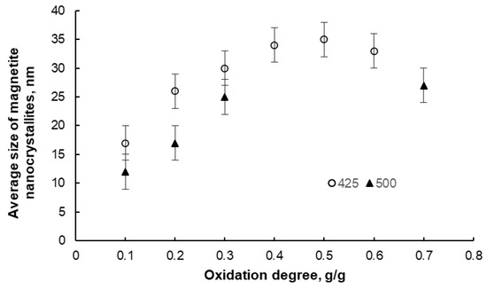
Figure 4.
Change in the average size of magnetite nanocrystallites in samples oxidized to different oxidation degrees at 425 °C and 500 °C (error bars are also marked).
The next step was to dissolve one of the crystallographic phases simultaneously present in the S0 samples after oxidation to specific conversion degrees. At this stage, the following observations were made:
- Nitric acid: For all samples etched for approximately 4 h, it was found that the average size of nanocrystallites of both phases did not increase. However, the samples obtained within a single oxidation degree differed in phase composition—the degree of iron etching was not uniform. For the samples oxidized to α < 0.2 g/g and etched for 24 h, the phase composition was found to be uniform within a single oxidation degree (almost 100% magnetite), but the average size of magnetite nanocrystallites increased from a dozen or so to over 30 nm. In the samples oxidized to α > 0.2 g/g and etched for 24 h (samples composed of almost 100% magnetite), this phenomenon was not observed, and the average size of the nanocrystallites did not change before and after the etching process. The metallic and oxide phases dissolved to varying degrees in nitric acid, with high selectivity of this solvent in the Fe-Fe3O4 system.
- Hydrochloric acid: The etching time ranged from several to 24 h. Differences compared to tests using nitric acid include the lack of an increase in the size of magnetite nanocrystallites and lower selectivity (approx. 50% compared to nitric acid) in the Fe-Fe3O4 system.
Example images obtained by transmission electron microscopy (TEM) for the modified sample S2 after oxidation to an oxidation degree of 0.2 g/g and acid etching are presented in Figure S1 of the “Supplementary Materials”. They show nanocomposite agglomerates, which, at this stage, consist of numerous, fairly regular-sized nanocrystallites.
Based on the collected information presented above, a new generation of chemical methods for obtaining nanomaterials with specific nanocrystallite sizes was proposed, in which selective etching is performed in two stages. In the first stage, a 0.5-molar hydrochloric acid solution is used to reduce the metallic phase content of the sample relative to the metal oxide while maintaining the average nanocrystallite size of the oxide phase unchanged. In the second stage, a 0.1-molar nitric acid solution is used to completely remove the metallic phase. It was found that nitric acid exhibits greater selectivity for dissolving metal in the presence of its oxide compared to hydrochloric acid. However, due to the oxidizing properties of nitric acid, during etching processes longer than 5 h, it may cause the secondary formation of metal oxides from ions present in the solution, deposition of reaction products on the oxide-phase nanocrystallites, and, as a result, an increase in their average size. This proved particularly important for the samples with an oxidation degree of 0.1 and 0.2 g/g, where the optimal (close to stoichiometric) amount of the etching agent should be used to remove the maximum possible amount of metal (<100%) without changing the average size of the oxide nanocrystallites. It was found that at the above-mentioned acid concentrations, the etching process should take approximately 4 h in each acid. The metallic iron content in the samples did not exceed 20%. Samples oxidized to higher oxidation degrees should be etched for 16–20 h. The obtained samples then contained virtually 100% of the oxide phase, with an average nanocrystallite size unchanged compared to the corresponding samples after the oxidation process.
Exemplary results of the XRD measurements of the magnetite nanocrystallite average size performed after selective etching using the two-stage method are presented in Figure 5.
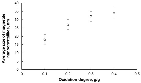
Figure 5.
Average size of magnetite nanocrystallites in samples oxidized to different oxidation degrees at 425 °C and then selectively etched using the two-step method (error bars are also marked).
Based on the XRD measurement results, it was also found that the samples oxidized to oxidation degrees in the range of 0.2–0.4 g/g consisted exclusively of magnetite after the etching process (excluding promoter oxides). The average size of nanocrystallites after this stage did not change compared to the samples after the oxidation stage. The samples oxidized to an oxidation degree of 0.1 g/g after etching contained approximately 20% metallic iron in addition to magnetite. However, both phases had similar nanocrystallite sizes (approximately 17 nm), and after reduction in hydrogen performed, for example, before the nitriding process, the sample contained one phase—iron. Therefore, it was concluded that metallic iron remaining in the samples after the etching process, within a certain concentration range, does not significantly affect the quality of the obtained nanomaterials, i.e., the average nanocrystallite size does not change, and the width of their size distribution does not increase after the reduction process. Indeed, after etching, the samples containing primarily nanocrystalline metal oxide were reduced with hydrogen at temperatures ranging from 375 to 500 °C. Before evacuation from the reactor, the nanomaterial must be passivated. The final result is a metallic nanomaterial with a defined average nanocrystallite size (the same values as in the case of magnetite) and a narrow size distribution (standard deviation of the size distribution, σ ≅ 3 nm).
The obtained samples of the nanomaterial with defined average iron nanocrystallite sizes and narrow size distributions were tested in the nitriding reaction with gaseous ammonia at 375 °C and in the catalytic decomposition reaction of ammonia at 500 °C. Exemplary results of thermogravimetric measurements (TG curves) for the cases of nitriding with 100% ammonia at the reactor inlet are shown in Figure 6.
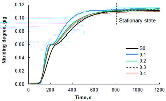
Figure 6.
Results of thermogravimetric measurements of the nitriding process of nanocrystalline iron samples (100% ammonia at the reactor inlet; temperature of 375 °C), which were oxidized to oxidation degrees of 0.1, 0.2, 0.3, and 0.4 g/g before selective etching. For comparison, the results for the unmodified S0 sample are also presented. The dashed line indicates the beginning of the stationary region (constant mass of the solid sample).
In addition to TG research, based on the results of the XRD tests of the samples nitrided to various nitriding degrees (0.02, 0.05, 0.06, 0.07, and 0.08 g/g), it was found that in the tested system, phase transformations occurred as follows: first α-iron to γ’-Fe4N nitride (first and second nitriding degrees tested; a stable mixture of α-iron and γ’-nitride was observed) and γ’-Fe4N nitride to ε-Fe3-2N nitride (fourth and fifth nitriding degrees tested; a stable mixture of γ’-nitride and ε-nitride was observed). For the sample with a nitriding degree of 0.06 g/g, practically one phase, i.e., γ’-Fe4N nitride, was detected.
Differences were observed in the shapes of the TG curves obtained for the modified (etched) samples and the reference sample S0. The inflection on the TG line, indicating the moment of phase transformations from α-iron to γ’-Fe4N nitride and then to ε-Fe3-2N near the nitriding degree of 0.058 g of nitrogen/g of iron, is less clearly visible in the TG curve for the unmodified sample than for the modified samples. This is due to the relatively broad distribution of nanocrystallite sizes in the S0 sample. As a result, the phase transition boundary points become blurred, as nanocrystallites within a wide size range undergo phase transformation gradually over a relatively long time interval, typically on the order of several tens of seconds. The modified samples are characterized by a relatively narrow range of nanocrystallite sizes. In this case, almost all nanocrystallites undergo phase transformation at virtually the same time, i.e., within a few seconds. Phase transition boundary points in such samples are more clearly visible. These differences are even more pronounced when comparing the nitriding rates of the modified and reference samples.
The measured mass increases that occurred during the nitriding process (Figure 6) were used to determine the nitriding reaction rate of the tested nanomaterials (DTG curves, Figure 7). To facilitate interpretation, Figure 7 shows only selected data sets for the modified samples with a narrow range of nanocrystallite sizes and for the unmodified sample. It was found that the maximum nitriding reaction rate is approximately twice as high for the modified sample “0.1” compared to the reference sample S0. The nitriding rates of the remaining samples do not differ significantly, but a relationship is visible. With an increasing oxidation degree, the maximum reaction rate decreases, and its location shifts towards longer times, counted from the moment of introducing ammonia into the reactor. The lowest maximum value and the one shifted furthest in time were recorded for the reference sample. Another important difference is the clear separation of two areas with different rate maxima (the appearance of two separate “peaks”) for the formation of the γ’ and ε phases in the modified samples. Between these two “peaks” is an area where the nitriding reaction rate is zero. This means that the α-Fe in the samples undergoes a phase transformation to γ’ within a short period of time, whenever possible. After the first phase transformation, no further nitriding reaction occurs until conditions occur in the system under which a phase transformation to the ε phase is possible. In the case of sample S0, only a local minimum is observed between the γ’ and ε phase formation region, but the reaction rate does not reach zero (the “peaks” overlap), because nanocrystallites across a wide range of sizes gradually undergo phase transformations, and the nitriding reaction proceeds practically continuously. This confirms the finding that the modified samples are characterized by a significantly narrowed range of nanocrystallite sizes compared to sample S0. It can therefore be concluded that in the case of the modified samples, there is a dependence of the activity of nanocrystalline iron in the nitriding reaction on the size of nanocrystallites—the smaller the nanocrystallites, the higher the activity of the tested sample.
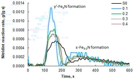
Figure 7.
Nitriding process rates of nanocrystalline iron samples, which were oxidized to oxidation degrees of 0.1–0.4 g/g before selective etching, and the unmodified S0 sample; 100% ammonia at the reactor inlet, 375 °C. For comparison, the results for the unmodified S0 sample (100% ammonia at the reactor inlet, 375 °C) are also presented.
However, in order to avoid the formation of mixtures of different crystallographic phases, the synthesis of nanocrystalline iron nitrides was carried out at nitriding potential P = 0.02 Pa−1/2 and at 375 °C. According to XRD, we indicated 100% γ’-phase in these materials, as in [80]. Figure 8a presents exemplary results regarding the average size of γ’-Fe4N nitride nanocrystallites (standard deviation of the size distribution, σ ≅ 5 nm) for the samples oxidized to various oxidation degrees in the range of 0.05–0.22 g/g and nitrided using the above-mentioned method. For comparison, the average size of magnetite nanocrystallites before and after the selective etching step of metallic iron from the oxidized samples is also shown. It was observed that, in accordance with the adopted assumptions of the nanocrystallite segregation method, the average size of both magnetite nanocrystals (before and after the selective dissolution of metallic iron) and γ’-Fe4N nitride increases with an increasing oxidation degree. However, the sizes of the nitride nanocrystallites are significantly larger than the initial magnetite nanocrystallites. This may be due to the interaction between nitrogen and iron during the nitriding process and the phase transformations that occur there. This may lead to a change in the nanocrystalline structure of the tested nanomaterials. Another cause may be a deficiency of calcium oxide stabilizing the nanostructure (CaO as a structural promoter, similar to Al2O3, ensures the stability of the nanocrystalline structure even at high temperatures due to achieving a thermodynamic equilibrium state in the nanocrystalline metal–promoter system [47]) in the samples at this stage of the work, as a result of reaction with acid. This means that samples poorer in structural promoters are more sensitive to high temperature. However, the addition of promoters at the melting stage resulted in an increase in the thermal stability of the nitrided samples (no growth of nanocrystallites in chemical reaction products to a coarse crystalline scale was observed, similar to the relationship for iron carbide—Figure 8b).
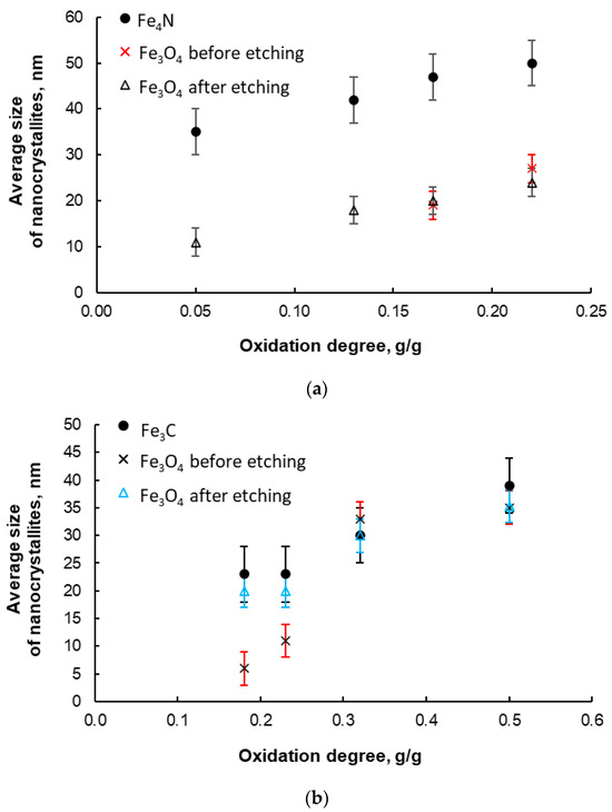
Figure 8.
(a) Average size of γ’ iron nitride nanocrystallites; nitriding at 375 °C, nitriding potential P = 0.02 Pa−1/2; during preparation, the samples were oxidized to various oxidation degrees in the range of 0.05–0.22 g/g. For comparison, the average size of magnetite nanocrystallites before and after the stage of selective etching of metallic iron from oxidized samples is shown. (b) Average size of Fe3C iron carbide nanocrystallites; carburizing at 465 °C, ethene/hydrogen ratio = 0.1; during preparation, the samples were oxidized to various oxidation degrees in the range 0.18–0.50 g/g. For comparison, the average size of magnetite nanocrystallites before and after the selective etching stage of metallic iron from oxidized samples is shown (error bars are also marked).
During the synthesis of iron carbides, it was found that only the use of ethene/hydrogen mixtures in a 1:10 ratio enabled the production of nanocrystalline iron carbide with specific nanocrystallite sizes in a controlled manner. Exemplary measurement results obtained by the XRD method (average nanocrystallite sizes of carbide and magnetite—for comparison) are given in Figure 8b. It was found that there was a correct trend of increasing dependence of the average cementite nanocrystallite size on the oxidation degree.
For iron oxides and metallic iron, a series of samples oxidized to various oxidation degrees in the range of 0.1–0.4 g/g and etched were prepared as well (they contained almost 100% magnetite—as measured by XRD). Some samples were reduced with hydrogen (500 °C) and only passivated, and then their average nanocrystallite sizes and nanocrystallite size distributions were determined (phase analysis showed 100% metallic iron). All the obtained samples had a narrowed iron nanocrystallite size distribution. (The standard deviation of the size distribution for both iron and magnetite was σ ≅ 3 nm; the average sizes of both iron and magnetite nanocrystallites were very similar to each other and dependent on the oxidation degree during the synthesis of nanocomposites. Therefore, in Figure 4, Figure 5 and Figure 8, we present the results only for one phase—magnetite.) The samples oxidized to oxidation degrees of 0.1, 0.2, 0.3, and 0.4 g/g had average iron nanocrystallite sizes of 20 nm, 30 nm, 35 nm, and 34 nm, respectively. The specific surface areas (measured by the BET methodology) of the above-mentioned samples were 30 m2/g, 22 m2/g, 16 m2/g, and 17 m2/g.
At 375 °C, the temperature at which nitride nanomaterials were synthesized, catalytic ammonia decomposition is practically unmeasurable in the setup used. Therefore, to measure the reaction rate, rdec, the nitriding process was conducted at 500 °C. Based on the steady-state gas phase composition measurements, the activity of the tested samples in the catalytic ammonia decomposition reaction was determined. The ammonia decomposition reaction rate was calculated per gram of iron contained in the sample. This enabled a comparison of the activity of nanocrystalline iron samples with different nanocrystallite size distributions in the catalytic ammonia decomposition reaction. For comparison, the ammonia decomposition rate was measured on a reference S0 sample under the same conditions. The nitrided samples were reduced with hydrogen and passivated, and their specific surface areas were determined to decrease from 32 to 16 m2/g with increasing nanocrystallite size. Samples with narrowed iron nanocrystallite size distributions were obtained (parameter σ ≅ 5 nm). Figure 9 presents the relative rate constants of the catalytic ammonia decomposition reaction (k = rdec/P) for individual samples, related to the reaction rate constant, k0, for sample S0. The above comparison shows that the obtained modified samples with a narrow nanocrystallite size distribution are much more active in the catalytic decomposition of ammonia than the unmodified S0 sample, and their activity is inversely dependent on the average size of nanocrystallites in the sample (and thus directly proportional to the specific surface area of the samples).
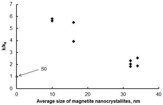
Figure 9.
Dependence of the relative reaction rate constants of the catalytic ammonia decomposition of the modified samples relative to the rate constant of this reaction for the S0 sample (◆) on the average size of magnetite nanocrystallites remaining in the samples after the selective etching step. For comparison, the ammonia decomposition rate on the S0 sample is also shown.
The point for sample S0 in Figure 9 falls outside the trend, which is clearly visible for the modified samples. It turns out that this sample, despite the relatively low mean nanocrystallite size (23 nm), is the least active of all the samples tested. This is likely due to the fact that this sample also has the least developed specific surface area (9 m2/g as determined by BET). This, in turn, may be the result of both a broad nanocrystallite size distribution (σ = 15 nm) and the presence of a larger number of nanocrystallite agglomerates instead of truly single, separated nanocrystallites, as may be the case in modified samples (etched with acids) with a narrow nanocrystallite size distribution.
The segregation method was also tested in a setup for synthesizing samples with a weight range of 10–100 g (to demonstrate the scalability of the segregation method). As with the 1 g samples, the average size of magnetite nanocrystallites before and after the etching process did not change significantly (Figure 10)—scaling to a larger scale was successful.
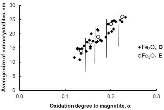
Figure 10.
Average size of magnetite nanocrystallites in samples after oxidation (O) and etching (E)—larger scale of synthesis. Vertical lines delimit the areas of individual oxidation states (0.12, 0.15, 0.18, 0.20, 0.23 g/g).
The nitriding, carburizing and ammonia decomposition processes carried out on scaled-up samples under identical conditions as for 1-g samples led to results consistent with those presented above for the listed processes.
4. Conclusions
A new, third-generation chemical method for segregating nanocrystallites of specific sizes was proposed. The use of a two-stage etching process makes the method more precise. Samples were obtained with a significantly narrowed nanocrystallite size distribution (within a few nanometers of the size distribution width) compared to the unmodified sample (the size distribution width was 15 nm). Promoters introduced into the melt, as in the second-generation method, ensure the stability of the nanocomposite structure at elevated temperatures.
Chemical Potential Programmed Reaction method [81,82], was also used for in situ studies of the nitriding reaction (in the high-temperature XRK reaction chamber of a Philips X-ray diffractometer) of unmodified samples and those with a narrow range of iron nanocrystallite sizes currently obtained. A several-fold reduced width of the nanocrystallite size distribution was confirmed in samples modified according to the developed nanocrystallite segregation method: in the segregated samples, the range of changes in the average iron nanocrystallite sizes during the nitriding process was over 2.5 times smaller compared to the unmodified sample. It was also found that the nanocrystallite size distribution in these samples was unimodal, while in the unmodified S0 sample, it was bimodal. In the range of ln P = −5 ÷ −3, two crystallographic phases (iron and iron nitride Fe4N) coexisted in equilibrium in the nanomaterial.
The scalability of the proposed method was also investigated, conducting measurements on 1, 10, and 100 g samples. The effect of nanocrystallite size on the chemical properties of the tested samples was observed. Nanocomposite samples containing the smallest iron nanocrystallites proved to be the most active in the nitriding reaction and catalytic ammonia decomposition. All the modified samples tested were at least several times more active in ammonia decomposition than the unmodified sample.
In summary, using a third-generation chemical method for isolating nanocrystallites of defined sizes, in which the etching stage is performed in two steps, the initial nanocrystalline collection was separated into fractions of defined nanocrystallite sizes, and some of their chemical properties were investigated. Interesting new results were obtained, and both the method and the model of reactions in the adsorption region underlying it were validated and verified. It turns out that double etching results in a more precise narrowing of the nanocrystallite size range in the solid samples studied.
Supplementary Materials
The following supporting information can be downloaded at: https://www.mdpi.com/article/10.3390/app152111752/s1, Figure S1: Transmission electron microscopy (TEM) images of the modified sample S2 after the oxidation and acid etching process: (a) an agglomerate of several dozen nanocrystallites, (b) collection of many agglomerates and porous structure of the sample; Table S1: X-Ray Diffraction data for samples S0–S4 at different stages of synthesis.
Author Contributions
Conceptualization, R.P.; methodology, E.E. and R.P.; validation, E.E., I.M., and R.J.; formal analysis, R.P. and E.E.; investigation, E.E., U.N., I.M. and R.J.; data curation, E.E.; writing—original draft preparation, R.P. and U.N.; writing—review and editing, R.P., E.E. and R.J.; visualization, E.E., U.N., I.M. and R.J.; supervision, R.P.; project administration, R.P.; funding acquisition, R.P. All authors have read and agreed to the published version of the manuscript.
Funding
This research was funded by the National Science Centre, Poland, under the program “Opus”, project no. 2017/27/B/ST8/02970, and by the National Centre for Research and Development, under the program “Lider”, project no. LIDER/025/489/L-5/13/NCBR/2014.
Institutional Review Board Statement
Not applicable.
Informed Consent Statement
Not applicable.
Data Availability Statement
The original contributions presented in the study are included in the article/Supplementary Materials, further inquiries can be directed to the corresponding author.
Acknowledgments
Special thanks to Anna Jędrzejewska for preparing images using transmission electron microscopy and Urszula Nowosielecka for performing measurements using the thermogravimetric method.
Conflicts of Interest
The authors declare no conflicts of interest.
References
- Nowosielecka, U.; Pelka, R.; Moszyńska, I.; Guskos, N.; Typek, J.; Żołnierkiewicz, G. Studies of magnetic properties of nano-crystalline iron of different sizes of nanocrystallites. J. Magn. Magn. Mater. 2017, 443, 324–333. [Google Scholar] [CrossRef]
- Pelka, R.; Nowosielecka, U.; Klimza, K.; Moszyńska, I.; Aidinis, K.; Żołnierkiewicz, G.; Guskos, A.; Guskos, N. Nanocrystalline Iron Oxides with Various Average Crystallite Size Investigated Using Magnetic Resonance Method. Crystals 2024, 14, 363. [Google Scholar] [CrossRef]
- Wang, Z.Q.; Xue, Y.Q.; Cui, Z.X.; Duan, H.J.; Xia, X.Y. The size dependence of dissolution thermodynamics of nanoparticles. Nano 2016, 11, 1650100. [Google Scholar] [CrossRef]
- Murzin, D.Y. On Cluster Size Dependent Activity and Selectivity in Heterogeneous Catalysis. Catal. Lett. 2012, 142, 1279–1285. [Google Scholar] [CrossRef]
- Zhou, X.; Xu, W.; Liu, G.; Panda, D.; Chen, P. Size-Dependent Catalytic Activity and Dynamics of Gold Nanoparticles at the Single-Molecule Level. J. Am. Chem. Soc. 2010, 132, 138–146. [Google Scholar] [CrossRef]
- Murzin, D.Y. Kinetic analysis of cluster size dependent activity and selectivity. J. Catal. 2010, 276, 85–91. [Google Scholar] [CrossRef]
- Yang, C.C.; Mai, Y.W. Thermodynamics at the nanoscale: A new approach to the investigation of unique physicochemical properties of nanomaterials. Mater. Sci. Eng. R 2014, 79, 1–40. [Google Scholar] [CrossRef]
- Qi, W.H. Nanoscopic thermodynamics. Acc. Chem. Res. 2016, 49, 1587. [Google Scholar] [CrossRef]
- Wang, Y.; Cui, Z.; Xue, Y.; Zhang, R.; Yan, A. Size dependent thermodynamic properties of two types of phase transitions of nano-Bi2O3 and their differences. J. Phys. Chem. C 2019, 123, 19135–19141. [Google Scholar] [CrossRef]
- Jiang, Q.; Li, J.C.; Chi, B.Q. Size-dependent cohesive energy of nanocrystals. Chem. Phys. Lett. 2002, 366, 551. [Google Scholar] [CrossRef]
- Guisbiers, G. Size-dependent materials properties toward a universal equation. Nanoscale Res. Lett. 2010, 5, 1132. [Google Scholar] [CrossRef] [PubMed]
- Xiong, S.; Qi, W.; Cheng, Y.; Huang, B.; Wang, M.; Li, Y. Universal relation for size dependent thermodynamic properties of metallic nanoparticles. Phys. Chem. Chem. Phys. 2021, 13, 10652. [Google Scholar] [CrossRef] [PubMed]
- Lee, J.; Sim, K.J. General equations of CALPHADtype thermodynamic description for metallic nanoparticle systems. Calphad 2014, 44, 129–132. [Google Scholar] [CrossRef]
- Vegh, A.; Kaptay, G. Modelling surface melting of macro-crystals and melting of nano-crystals for the case of perfectly wetting liquids in one-component systems using lead as an example. Calphad 2018, 63, 37–50. [Google Scholar] [CrossRef]
- Ansari, A.M. Modelling of size-dependent thermodynamic properties of metallic nanocrystals based on modified Gibbs-Thomson equation. Appl. Phys. A 2021, 385, 1. [Google Scholar]
- Yakymovych, A.; Kaptay, G.; Flandorfer, H.; Bernardi, J.; Schwarz, S.; Ipser, H. The nano heat effect of replacing macro-particles by nano-particles in drop calorimetry: The case of core/shell metal/oxide nano-particles. RSC Adv. 2018, 8, 8856–8869. [Google Scholar] [CrossRef]
- Kaptay, G. The chemical (not mechanical) paradigm of thermodynamics of colloid and interface science. Adv. Colloid Interface Sci. 2018, 256, 163–192. [Google Scholar] [CrossRef]
- Vykoukal, V.; Zelenka, F.; Bursik, J.; Kana, T.; Kroupa, A.; Pinkas, J. Thermal properties of Ag@Ni core-shell nanoparticles. Calphad 2020, 69, 101741. [Google Scholar] [CrossRef]
- Samsonov, V.M.; Vasilyev, S.A.; Nebyvalova, K.K.; Talyzin, I.V.; Sdobnyakov NYu Sokolov, D.N.; Alymov, M.I. Melting temperature and binding energy of metal nanoparticles: Size dependences, interrelation between them, and some correlations with structural stability of nanoclusters. J. Nanoparticle Res. 2020, 22, 247. [Google Scholar] [CrossRef]
- Chen, Y.; Lai, Z.; Zhang, X.; Fan, Z.; He, Q.; Tan, C.; Zhang, H. Phase engineering of nanomaterials. Nat. Rev. Chem. 2020, 4, 243–256. [Google Scholar] [CrossRef] [PubMed]
- Minenkov, A.; Groiss, H. Evolution of phases and their thermal stability in Ge-Sn nanofilms: A comprehensive in situ TEM investigation. J. Alloys Compd. 2021, 859, 157763. [Google Scholar] [CrossRef]
- Kim, H.G.; Lee, J.; Makov, G. Phase diagram of binary alloy nanoparticles under high pressure. Materials 2021, 14, 2929. [Google Scholar] [CrossRef]
- Taranovskyy, A.; Tomán, J.J.; Gajdics, B.D.; Erdélyi, Z. 3D phase diagrams and the thermal stability of two-component Janus nanoparticles: Effects of size, average composition and temperature. Phys. Chem. Chem. Phys. 2021, 23, 6116–6127. [Google Scholar] [CrossRef] [PubMed]
- Coviello, V.; Forrer, D.; Amendola, V. Recent developments in plasmonic alloy nanoparticles: Synthesis, modelling, properties and applications. Chem. Phys. Chem. 2022, 23, e202200136. [Google Scholar] [CrossRef]
- Yao, X.; Liu, G.J.; Lang, X.Y.; Li, H.D.; Zhu, Y.F.; Jiang, Q. Effects of surface and grain boundary on temperature-pressure nano-phase diagrams of nanostructured carbon. Scripta Mater. 2022, 207, 114267. [Google Scholar] [CrossRef]
- Chu, M.Z.; Zhang, C.; Liang, X.H.; Hu, C.H.; Ma, G.T.; Fang, R.Y.; Tang, C.Y. Melting and phase diagram of Au-Cu alloy at nanoscale. J. Alloys Compd. 2022, 891, 162029. [Google Scholar] [CrossRef]
- Korte-Kerzel, S.; Hickel, T.; Huber, L.; Raabe, D.; Sandlöbes-Haut, S.; Todorova, M.; Neugebauer, J. Defect phases–thermodynamics and impact on material properties. Int. Mater. Rev. 2022, 67, 89–117. [Google Scholar] [CrossRef]
- Wieczerzak, K.; Sharma, A.; Hain, C.; Michler, J. Crystalline or amorphous? A critical evaluation of phenomenological phase selection rules. Mater. Des. 2023, 230, 111994. [Google Scholar] [CrossRef]
- Tulinski, M.; Jurczyk, M. Nanomaterials Synthesis Methods. In Metrology and Standardization of Nanotechnology; Mansfield, E., Kaiser, D.L., Fujita, D., Van de Voorde, M., Eds.; Wiley-VCH Verlag GmbH & Co. KGaA: Weinheim, Germany, 2017. [Google Scholar] [CrossRef]
- Baig, N.; Kammakakam, I.; Falath, W. Nanomaterials: A review of synthesis methods, properties, recent progress, and challenges. Mater. Adv. 2021, 2, 1821–1871. [Google Scholar] [CrossRef]
- Yamamoto, K.; Imaoka, T. Precision Synthesis of Subnanoparticles Using Dendrimers as a Superatom Synthesizer. Acc. Chem. Res. 2014, 47, 1127–1136. [Google Scholar] [CrossRef]
- Mekuye, B.; Abera, B. Nanomaterials: An overview of synthesis, classification, characterization, and applications. Nano Select 2023, 4, 486–501. [Google Scholar] [CrossRef]
- Arabczyk, W.; Lendzion-Bieluń, Z.; Wróbel, R. Method for Obtaining Nanomaterials Featuring Defined Size of Crystallites. PL36125603A, 24 January 2005. Available online: https://eprofil.pue.uprp.gov.pl/public/registry/view/Pat.206909?lng=pl (accessed on 31 October 2005).
- Wróbel, R.; Arabczyk, W. Solid−Gas Reaction with Adsorption as the Rate Limiting Step. J. Phys. Chem. A 2006, 110, 9219–9224. [Google Scholar] [CrossRef]
- Wróbel, R.J. Thermal stability of nanocrystalline iron. Mater. Sci. Pol. 2012, 30, 63–69. [Google Scholar] [CrossRef]
- Arabczyk, W.; Wróbel, R. Study of the Kinetics of Nitriding of Nanocrystalline Iron Using TG and XRD Methods. Solid State Phenom. 2003, 94, 185–188. [Google Scholar] [CrossRef]
- Arabczyk, W.; Wróbel, R. Utilisation of XRD for the Determination of the Size Distribution of Nanocrystalline Iron Materials. Solid State Phenom. 2003, 94, 235–238. [Google Scholar] [CrossRef]
- Narkiewicz, U.; Arabczyk, W.; Konicki, W. Studies of the Kinetics of the Carbon Deposit Formation in the Decomposition of Methane on Nanocrystalline Iron. Fullerenes, Nanotubes. Carbon Nanostruct. 2005, 13, 99–105. [Google Scholar] [CrossRef]
- Arabczyk, W.; Konicki, W.; Narkiewicz, U.; Jasińska, I.; Kałucki, K. Kinetics of the Iron Carbide Formation in the Reaction of Methane with Nanocrystalline Iron Catalyst. Appl. Catal. A 2004, 266, 135–145. [Google Scholar] [CrossRef]
- Narkiewicz, U.; Arabczyk, W.; Konicki, W.; Pattek-Janczyk, A. Nucleation of the Fe3C in reaction of methane with nanocrystalline iron. J. Mater. Res. 2005, 20, 386–393. [Google Scholar] [CrossRef]
- Narkiewicz, U.; Arabczyk, W.; Konicki, W.; Kucharewicz, I. Studies of the kinetics of methane decomposition on the nanocrystalline iron to carbon deposition formation. Rev. Adv. Mater. Sci. 2004, 8, 53–58. [Google Scholar]
- Narkiewicz, U.; Guskos, N.; Arabczyk, W.; Typek, J.; Bodziony, T.; Konicki, W.; Gąsiorek, G.; Kucharewicz, I.; Anagnostakis, E.A. XRD, TEM and magnetic resonance studies of iron carbide nanoparticle agglomerates in a carbon matrix. Carbon 2004, 42, 1127–1132. [Google Scholar] [CrossRef]
- Lubkowski, K.; Arabczyk, W.; Grzmil, B.; Michalkiewicz, B.; Pattek-Janczyk, A. Passivation and oxidation of an ammonia iron catalyst. Appl. Catal. A 2007, 329, 137–147. [Google Scholar] [CrossRef]
- Arabczyk, W.; Pelka, R.; Jasińska, I.; Lendzion-Bieluń, Z. Reaction Model Taking into Account the Catalyst Morphology and Its Active Specific Surface in the Process of Catalytic Ammonia Decomposition. Materials 2021, 14, 7229. [Google Scholar] [CrossRef]
- Arabczyk, W.; Pelka, R.; Wilk, B.; Lendzion-Bieluń, Z. Kinetics and thermodynamics of the phase transformation in the nanocrystalline substance—Gas phase system. Crystals 2024, 14, 129. [Google Scholar] [CrossRef]
- Narkiewicz, U.; Podsiadły, M.; Jędrzejewski, R.; Pełech, I. Catalytic decomposition of hydrocarbons on cobalt, nickel and iron catalysts to obtain carbon nanomaterials. Appl. Catal. A 2010, 384, 27–35. [Google Scholar] [CrossRef]
- Arabczyk, W.; Pelka, R.; Jasińska, I.; Lendzion-Bieluń, Z. Thermodynamics of Iron Ammonia Synthesis Catalyst Sintering. Crystals 2024, 14, 188. [Google Scholar] [CrossRef]
- Pelka, R.; Glinka, P.; Arabczyk, W. The Influence of Iron Nanocrystallite Size on a Nitriding Process Rate. Mater. Sci. Pol. 2008, 26, 349–356. [Google Scholar]
- Pelka, R.; Arabczyk, W. Modelling of Nanocrystalline Iron Nitriding Process—Influence of Specific Surface Area. Chem. Pap. 2011, 65, 198–202. [Google Scholar] [CrossRef]
- Arabczyk, W.; Pelka, R.; Brzoza-Kos, A.; Kocemba, I.; Rokicka-Konieczna, P.; Skulmowska-Polok, K.; Klimza, K.; Lendzion-Bieluń, Z. Studies of Phase Transformation Kinetics in the System of Nanocrystalline Iron/Ammonia/Hydrogen at the Temperature of 350 °C by Means of Magnetic Permeability In Situ Measurement. Appl. Sci. 2024, 14, 8452. [Google Scholar] [CrossRef]
- Pelka, R.; Arabczyk, W. A New Method for Determining the Nanocrystallite Size Distribution in Systems where Chemical Reaction between Solid and a Gas Phase Occurs. J. Nanomater. 2013, 2013, 645050. [Google Scholar] [CrossRef]
- Pelka, R. A Method of Determining Nanoparticle Size Distribution in Iron Ammonia Synthesis Catalyst by Measuring Mass Changes During the Nitriding Process. Catal. Today 2017, 286, 118–123. [Google Scholar] [CrossRef]
- Moszyńska, I.; Moszyński, D.; Arabczyk, W. Hysteresis in nitriding and reduction in the nanocrystalline iron-ammonia-hydrogen system. Przem. Chem. 2009, 88, 526–529. [Google Scholar]
- Moszyński, D.; Kiełbasa, K.; Arabczyk, W. Influence of crystallites’ size on iron nitriding and reduction of iron nitrides in nanocrystalline Fe-N system. Mater. Chem. Phys. 2013, 141, 674–679. [Google Scholar] [CrossRef]
- Arabczyk, W.; Ekiert, E.A.; Pelka, R. Hysteresis phenomenon in a reaction system of nanocrystalline iron and a mixture of ammonia and hydrogen. Phys. Chem. Chem. Phys. 2016, 18, 25796–25800. [Google Scholar] [CrossRef] [PubMed]
- Kaptay, G. The Gibbs equation versus the Kelvin and the Gibbs-Thomson equations to describe nucleation and equilibrium of nano-materials. J. Nanosci. Nanotechnol. 2012, 12, 2625–2633. [Google Scholar] [CrossRef]
- Dezso, A.; Kaptay, G. On the configurational entropy of nanoscale solutions for more accurate surface and bulk nano-thermodynamic calculations. Entropy 2017, 19, 248. [Google Scholar] [CrossRef]
- Kaptay, G. On the size- and shape-dependence of integral and partial molar Gibbs energies, entropies, enthalpies and inner energies of solid and liquid nano-particles. J. Mater. Sci. 2024, 59, 17444–17455. [Google Scholar] [CrossRef]
- Arabczyk, W.; Ekiert, E.; Pelka, R. Size-Dependent Transformation of α-Fe into γ′-Fe4N in Nanocrystalline the Fe–NH3–H2 System. J. Phys. Chem. C 2016, 120, 17989–17995. [Google Scholar] [CrossRef]
- Kaptay, G. A new paradigm on the chemical potentials of components in multi-component nano-phases within multi-phase systems. RSC Adv. 2017, 7, 41241–41253. [Google Scholar] [CrossRef]
- Vollath, D.; Fischer, F.D.; Holec, D. Surface energy of nanoparticles–influence of particle size and structure. Beilstein J. Nanotechnol. 2018, 9, 2265–2276. [Google Scholar] [CrossRef]
- Kaptay, G. On the size dependence of molar and specific properties of independent nano-phases and those in contact with other phases. J. Mater. Eng. Perf. 2018, 27, 5023–5029. [Google Scholar] [CrossRef]
- Shekhawat, D.; Vauth, M.; Pezoldt, J. Size dependent properties of reactive materials. Inorganics 2022, 10, 56. [Google Scholar] [CrossRef]
- Chesnokov, V.V.; Chichkan, A.S.; Parmon, V.N. Formation of Carbon from High-Molecular Hydrocarbons on Iron Subgroup Metals on the Sibunite Carbon Support. Catal. Ind. 2018, 10, 244–250. [Google Scholar] [CrossRef]
- Grabke, H.J. Thermodynamics, Mechanisms and Kinetics of Metal Dusting. Mater. Corros. 1998, 49, 303–308. [Google Scholar] [CrossRef]
- Schneider, A.; Viefhaus, H.; Inden, G. Surface Analytical Studies of Metal Dusting of Iron in CH4-H2-H2S Mixtures. Mater. Corros. 2000, 51, 338–343. [Google Scholar] [CrossRef]
- Theofanidis SAGalvita, V.V.; Konstantopoulos, C.; Poelman, H.; Marin, B.G. Fe-Based Nano-Materials in Catalysis. Materials 2018, 11, 831. [Google Scholar] [CrossRef]
- Chesnokov, V.; Buyanov, R.A. Mechanism for the Formation of Carbon Deposits from Benzene on Iron and Nickel. Kinet. Catal. 1987, 28, 403–407. [Google Scholar]
- Wróbel, R.J.; Hełminiak, A.; Arabczyk, W.; Narkiewicz, U. Studies on the Kinetics of Carbon Deposit Formation on Nanocrystalline Iron Stabilized with Structural Promoters. J. Phys. Chem. C 2014, 118, 15434–15439. [Google Scholar] [CrossRef]
- Albert, M.R.; Sneddon, L.G.; Eberhardt, W.; Greuter, F.; Gustafsson, T.; Plummer, E.W. The Characterization of Surface Acetylene and Ethylene Species on Pt(111) by Angle Resolved Photoemission Using Synchrotron Radiation. Surf. Sci. 1982, 120, 19–37. [Google Scholar] [CrossRef]
- Yagasaki, E.; Backman, A.L.; Masel, R.I. The Adsorption and Decomposition of Ethylene on Pt(210), (1·1)Pt(110) and (2·1)Pt(110). Vacuum 1990, 41, 57–59. [Google Scholar] [CrossRef]
- Sheppard, N. Vibrational Spectroscopic Studies of the Structure of Species Derived from the Chemisorption of Hydrocarbons on Metal Single-Crystal Surfaces. Annu. Rev. Phys. Chem. 1988, 39, 589–644. [Google Scholar] [CrossRef]
- Gates, J.A.; Kesmodel, L.L. EELS Analysis of the Low Temperature Phase of Ethylene Chemisorbed on Pd(111). Surf. Sci. 1982, 120, L461–L467. [Google Scholar] [CrossRef]
- Steininger, H.; Ibach, H.; Lehwald, S. Surface Reactions of Ethylene and Oxygen on Pt(111). Surf. Sci. 1982, 117, 685–698. [Google Scholar] [CrossRef]
- Kesmodel, L.L.; Dubois, L.H.; Somorjai, G.A. Dynamical LEED Study of C2H2 and C2H4 Chemisorption on Pt(111): Evidence for the Ethylidyne C-CH3 Group. Chem. Phys. Lett. 1978, 56, 267–271. [Google Scholar] [CrossRef]
- Sacco, A., Jr. Carbon deposition and filament initiation and growth mechanism on iron particles and foils. In Carbon Fibers Filaments and Composites; Figueiredo, J.L., Bernardo, C.A., Baker, R.T.K., Hüttinger, K.J., Eds.; Kluwer Academic Publishers: Dordrecht, The Netherlands, 1990. [Google Scholar]
- Arabczyk, W.; Ziebro, J.; Kałucki, K.; Świerkowski, R.; Jakrzewska, M. Instalacja laboratoryjna do ciągłego wytopu kataliza-torów żelazowych. Chemik 1996, 1, 22. [Google Scholar]
- Pielaszek, R. FW15/45M method for determination of the grain size distribution from powder diffraction line profile. J. Alloys Compd. 2004, 382, 128–132. [Google Scholar] [CrossRef]
- Pielaszek, R. Analytical expression for diffraction line profile for polydispersive powders. In Applied Crystallography, Proceedings of the XIX Conference, Kraków, Poland, 1–4 September 2003; World Scientific Publishing: Singapore, 2004; pp. 43–50. [Google Scholar]
- Wilk, B.; Arabczyk, W. Investigation of nitriding and reduction processes in the nanocrystalline iron-ammonia-hydrogen system at 350 °C. Phys. Chem. Chem. Phys. 2015, 17, 20185–20193. [Google Scholar]
- Wilk, B.; Pelka, R.; Arabczyk, W. Study of the Iron Catalyst for Ammonia Synthesis by Chemical Potential Programmed Reaction Method. J. Phys. Chem. C 2017, 121, 8548–8556. [Google Scholar] [CrossRef]
- Ekiert, E.A.; Wilk, B.; Lendzion-Bieluń, Z.; Pelka, R.; Arabczyk, W. Study of Phase Transitions Occurring in a Catalytic System of ncFe-NH3/H2 with Chemical Potential Programmed Reaction (CPPR) Method Coupled with In Situ XRD. Catalysts 2021, 11, 183. [Google Scholar] [CrossRef]


Disclaimer/Publisher’s Note: The statements, opinions and data contained in all publications are solely those of the individual author(s) and contributor(s) and not of MDPI and/or the editor(s). MDPI and/or the editor(s) disclaim responsibility for any injury to people or property resulting from any ideas, methods, instructions or products referred to in the content. |
© 2025 by the authors. Licensee MDPI, Basel, Switzerland. This article is an open access article distributed under the terms and conditions of the Creative Commons Attribution (CC BY) license (https://creativecommons.org/licenses/by/4.0/).