Article

Analysis of the Possibilities of Using an Organic Bridging Material for Sealing the Borehole Wall

Oil and Gas Institute–National Research Institute, 31-503 Krakow, Poland
*
Author to whom correspondence should be addressed.
Appl. Sci. 2025, 15(21), 11601; https://doi.org/10.3390/app152111601
Submission received: 14 September 2025 / Revised: 28 October 2025 / Accepted: 29 October 2025 / Published: 30 October 2025

Abstract

The process of exploiting hydrocarbon deposits is subject to many complications, some of which can make exploitation very difficult or impossible. These factors include damage to the wellbore zone by drilling fluid, which impedes the flow of reservoir fluid from the production zone to the well. This article presents the results of research conducted to develop drilling fluid compositions with the best possible ability to form a tight sealing sediment on the borehole wall. In addition to traditional carbonate blockers, modern organic agents were used as bridging agents. Research was conducted on the selection of the drilling fluid composition, the rheological parameters of which would ensure the suspension of the solid phase in the form of various types of blockers. After preparing the base drilling fluid, its composition was modified by adding different configurations of blockers. The sets of blockers added to the fluid varied in both chemical structure and particle size. Such modified fluids were then subjected to tests of technological properties, such as rheological parameters, API filtration, and pH. In the next stage, sealing tests of the filter cake formed by the tested fluids were carried out on the surface of the rock core using the PPT—Pore Pressure Transmission Test. Based on the obtained results, it can be concluded that the new type of organic blockers used allows the rapid formation of a tight filter cake on the borehole wall, and thus significantly reduces drilling fluid filtration. During PPT, the sediment formation time (tpmax) for OB2 was 45 min; for the combination of OB1 and the carbonate inhibitor, it was 8 min; and for the carbonate inhibitor alone, it was 150 min.

1. Introduction

The drilling process often involves several unexpected events that can ultimately lead to significant losses of time and money. Therefore, companies continually strive to develop proactive and effective solutions to mitigate the consequences of such events (please add the reference here). One of the most critical challenges encountered during drilling operations is fluid loss, which can cause formation damage and, in more severe cases, lead to a kick and potentially a blowout. Consequently, companies focus on formulating drilling fluids that minimize these losses and enhance wellbore stability [1].
The use of proper drilling mud in the drilling process has a significant impact on the efficiency and quality of the work performed. Its primary task is to maintain the pressure balance between the fluid column and the formation pressure, which protects against the uncontrolled inflow of fluids from the formation and against rock damage resulting from excessive hydrostatic pressure. In addition, the drilling mud transports cuttings from the bottom of the hole to the surface, which ensures that the hole remains clear and prevents sediments from accumulating at the bottom of the hole. It also performs a cooling and lubricating function, dissipating the heat generated by the drill bit and drill string and reducing friction between the pipe and the borehole walls. The selection of the rheological and chemical properties of mud is essential to ensure the stability of the borehole walls, reduce clay swelling, and prevent mud boils. Thanks to the appropriate filtration properties of the mud, it is also possible to create a thin, tight layer of sediment (filter cake) that protects the formation from filtrate penetration and potential damage.
One of the most important roles of drilling mud is certainly to ensure the stability of the borehole during drilling. The stability of the borehole determines both the safety of the drilling process and the quality of the borehole. In order to provide stability, a combined approach is used, including both control of the hydrostatic pressure of the drilling mud and selection of the appropriate chemical composition of the mud. Maintaining the correct pressure in the hole—balancing but not exceeding the pressure in the formation—prevents both reservoir blowouts and rock bursts. At the same time, the rheological and chemical properties of the mud must be adapted to the type of rock being drilled, especially in the case of clays and shales, which tend to swell and soften when exposed to water. In such conditions, mud with clay hydration inhibitors is used [2,3].
Another important task of drilling mud is cleaning the borehole of cuttings. During drilling, rock fragments called cuttings are formed at the bottom of the hole. They must be continuously removed to the surface to prevent them from accumulating at the bottom of the hole. The efficiency of the cleaning process depends primarily on the rheological parameters of the drilling mud (plastic viscosity, yield point, and gelling capacity) and on the hydraulic conditions in the hole, such as the flow velocity in the annular space, the diameter of the hole, the angle of inclination, and the rotational speed of the pipe [4]. When classic drilling fluid circulation does not provide sufficient transport of cuttings, supporting devices such as hydroelevators and jet pumps are used. Their operation is based on the Venturi effect, which involves the creation of local negative pressure as a result of the flow of propellant fluid through a constriction, enabling the mixture of fluid and cuttings to be sucked up from the bottom of the hole. A hydroelevator, which uses a stream of mud or water at the appropriate pressure, allows for the effective removal of cuttings from the bottom of the hole, especially in sections with limited circulation, in directional holes, or during reconstruction work. Jet pumps, on the other hand, are used in perforation cleaning, sand removal, and well cleaning processes during production, especially when a traditional circulation system cannot be used [5,6].
The tasks of drilling mud also include cooling and lubrication of the drill bit and drill string. During the drilling process, a significant amount of heat is generated as a result of friction between the tools and the walls of the hole, which can accelerate equipment wear and, in extreme cases, lead to damage. Drilling mud removes heat from the bottom of the hole to the surface and acts as a lubricant, reducing friction between the drill string and the rock. This reduces torque and resistance in the annular space, facilitating penetration of the formation and increasing the drilling rate.
Drilling mud can perform the above tasks if its parameters have been correctly designed. Incorrect selection of mud can result in a number of complications, such as lost circulation, borehole instability, poor hole cleaning, or damage to the near-wellbore zone (Figure 1).
Damage to the near-wellbore zone is often the cause of a significant reduction in hydrocarbon production. It may occur during drilling, coring, casing, production, wellbore reconstruction, or secondary production enhancement techniques. In the drilling process, four main causes of permeability damage are distinguished [7,8,9,10,11,12,13,14]:
  • Blocking of pore channels by solid phase particles from the drilling fluid;
  • The effect of the aqueous phase on clay binders, causing their hydration and swelling or the dispersion of colloidal particles and pore clogging as they move with formation water;
  • Blocking by the aqueous phase, due to the invasion of water into the formation during drilling (water blockage);
  • Precipitation of insoluble deposits occurs when the alkaline filtrate from the drilling fluid comes into contact with mineralized formation water.
The reduction in permeability of the near-wellbore zone may also occur spontaneously after the long-term inflow of formation fluid from the productive layer. Depending on the degree of pressure drop and temperature around the wellbore during the influx of formation fluids, the precipitation of paraffin and asphalt compounds or emulsion formation may occur, causing pore space clogging and resulting in secondary permeability damage [12,15,16,17].
To reduce the damage to the permeability of the near-wellbore zone, specially selected polymer agents and a solid phase in the form of bridging materials (blockers) with particle sizes appropriate for the drilled rock are used in the compositions of drilling fluids. The primary task of the blockers is to protect the near-wellbore zone by forming a temporary filter cake on the borehole wall, limiting the invasion of filtrate from the drilling fluid into the pores of the reservoir rocks. By adding such materials to drilling fluids, parameters such as filtration and density can also be regulated. Therefore, when designing the composition of a drilling fluid, the amount of salts and bridging materials used should be considered to achieve a density appropriate for the geological and reservoir conditions [18,19,20,21].
The first group of bridging agents used in drilling technology is inorganic blockers, the most common of which is calcium carbonate—CaCO3. It naturally occurs as a constituent of various minerals (such as calcite) and rock formations, including dolomite, chalk, and marble. For use in drilling fluid technology, it is typically produced by grinding marble. Carbonate materials are available in a wide range of particle sizes, from just a few micrometers up to approximately 3 mm. Selecting an appropriate particle size enables the sealing of the filter cake, thereby effectively restricting the penetration of both the fluid and solid phases into reservoir rocks located in the near-wellbore zone. Owing to their broad particle size distribution, chemical inertness, and ease of removal from the borehole wall, carbonate agents are extensively employed not only as filtration-control additives but also as weighting materials in drilling fluids, allowing for densities up to 1.5 g/cm3 [22,23,24,25,26,27].
Calcium carbonate is characterized by its high solubility in acid and is frequently incorporated into the formulations of drilling fluids for the temporary sealing of the near-wellbore zone. Since it neither swells nor disperses in water or brine, it does not exhibit structure-forming properties. Consequently, to ensure the stability of the drilling fluid system, suitable polymers must be introduced to maintain its suspension within the liquid phase [12,28,29,30,31].
Another category of agents that has been rapidly gaining significance in drilling fluid technology is nanomaterials. Often described as intelligent drilling fluid systems, these so-called nanofluids are characterized by the presence of particles at the nanometer scale. Based on the number of nanometric additives, such fluids are classified as either simple nanofluids or advanced nanofluids. Systems containing only a single type of nanoparticle are referred to as simple nanofluids, whereas those incorporating multiple types of nanoparticles are designated as advanced nanofluids [32,33,34,35,36]. Silicon dioxide (silica, SiO2) is among the most widely utilized nanomaterials in the industry. Its broad availability, combined with its unique properties, has fostered its extensive application. Silica demonstrates resistance to both water and elevated temperatures, in addition to functioning as an effective insulator. Chemically inert, it reacts only with boiling, concentrated aqueous solutions of KOH and NaOH, molten Na2CO3 and K2CO3, and hydrofluoric acid and its aqueous solutions. Industrially manufactured silica nanoparticles typically exhibit diameters ranging from 5 to 1000 nm, with specific surface areas varying between 545 and 2.73 m2/g [37,38,39,40]. Numerous publications [41,42,43,44,45] confirm the high effectiveness of nanomaterials in reducing the filtration of drilling fluids and minimizing damage to the natural permeability of reservoir rocks. Studies show that materials with particle sizes of 5–15 nm are the most effective. They easily occupy the spaces between larger solid particles and weighting materials, effectively sealing the filter cake formed on the borehole wall and preventing filtrate from entering the pore channels of the drilled rock.
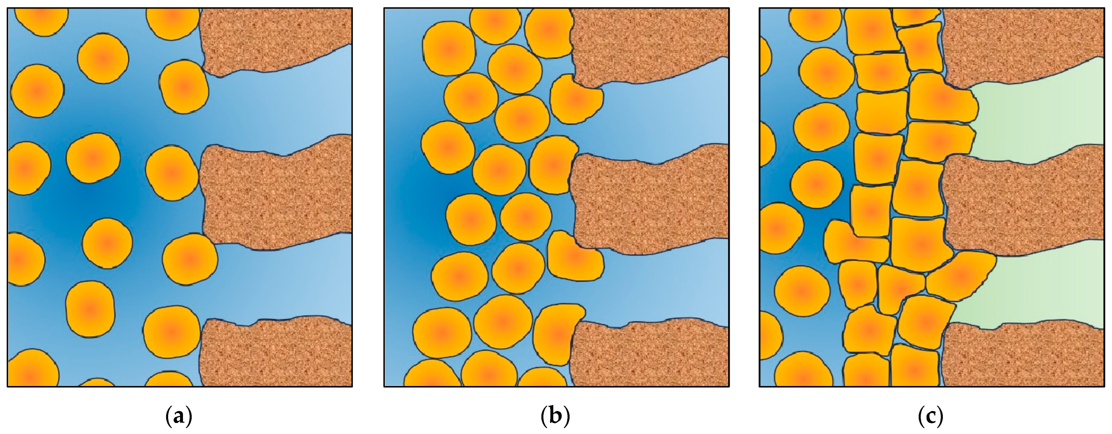
Another important group of agents used to create a tight filter cake are organic blockers, among which are cellulose-based materials. They can be produced, among other methods, from ground nutshells processed into cellulose powder. This material is inert, insoluble in water, resistant to elevated temperatures (up to 200 °C), and biodegradable [46,47,48]. Cellulose-based blockers are utilized in both drilling fluid formulations and working fluids of varying salinity, where rheological and structural properties, as well as filtration, are regulated by starch- or cellulose-based protective colloids and biopolymers. Owing to the diversity of particle sizes and shapes, the cellulose blocker facilitates the sealing off of reservoir rocks in the near-wellbore zone by creating an internal barrier within the pore spaces and forming a filter cake on the borehole wall. A pressure differential is required to achieve sealing, as it enables the flexible blocker particles to establish a highly effective barrier along the borehole wall (Figure 2). The resulting filter cake is highly resistant to high pressures and has low permeability. The destruction of the sealing structure and unblocking of the near-wellbore zone most often occurs as a result of depression in the well during production start-up [12,46].

Research Aims

Despite significant progress in the development of blocking materials, which are used in drilling mud to reduce filtration and protect the permeability of the near-wellbore zone, there are still new areas of development. Review studies have identified a wide range of strategies—from conventional granular and fibrous materials, through bridge-forming polymers, to modern nanocomposites that improve filter cake formation [49,50].
Many of the drilling mud filtration reduction agents currently being studied are organic materials of natural origin. The authors of article [51] discuss the possibility of using agro-waste materials like ground orange peel and sunflower seeds. These agents may be effective in reducing filtration, but their use results in an increase in rheological properties such as viscosity and yield point. Another environmentally friendly agent whose potential use in mud technology is discussed in article [52] is sawdust. The authors point out that the filter cake formed from mud containing sawdust is thinner and has a slippery surface, which can reduce the friction between the drill pipe and the borehole wall. However, too high a content can significantly increase the rheological parameters. The authors of article [53] also describe the possibility of using locally available, sustainable, eco-friendly, and low-cost materials such as cow bone powder (CBP) as an additive to reduce filtration in drilling mud. In the presented results, they compare the effect of CBP with that of commonly used calcium carbonate. The results show that the use of a fine fraction can effectively reduce filtration. However, aging under elevated temperature conditions caused a significant increase in mud viscosity.
As can be seen, modern mud technology focuses not only on maximum efficiency but also places great emphasis on environmental protection. The aim of this work was to develop a drilling mud composition capable of forming a tight filter cake that prevents mud filtrate invasion and limits pore pressure growth in the drilled rock formation, using an agent with the least possible impact on the natural environment. A new type of bridging agent used in the mud composition, which is a mixture of flexible particles of specially modified cellulose and hard grains of natural origin, was responsible for the formation of a tight and flexible filter cake on the borehole walls.

2. Materials and Methods

2.1. Methodology Overview

In the first stage of the study, blocking materials were selected whose purpose was to quickly form a filter cake, temporarily sealing the near-wellbore zone and preventing filtrate from penetrating the reservoir rocks. These were as follows:
  • A carbonate blocker;
  • Organic blocker OB1;
  • Organic blocker OB2;
  • Organic blocker OB3.
The next step was to select a drilling fluid to be subsequently modified by the addition of blocking agents. A polymer–potassium drilling fluid was chosen, composed of the following structural polymers: XCD biopolymer, polyanionic cellulose, and pregelatinized starch, while potassium chloride was used as a clay-rock hydration inhibitor.
Then, drilling fluid samples with different concentrations of structuring polymers and the addition of blocking agents at a concentration of 5.0% were tested for stability over 24 h using the Turbiscan Tower apparatus (Formulaction Inc., Toulouse, France). The purpose of this study was to select the optimal composition of the base drilling fluid, whose rheological and structural parameters ensured structural stability and prevented sedimentation of the blockers.
The chosen composition, characterized by the highest stability, was then modified using single blocking materials at concentrations of 1.0%, 3.0%, and 5.0%, as well as various configurations of blocking materials at the following concentrations:
  • 4.0%/1.0%;
  • 3.0%/2.0%;
  • 2.0%/3.0%;
  • 4.0%/1.0%.
The drilling fluids obtained in this way were subjected to tests of technological properties, such as rheological and structural parameters, filtration, and pH.
In the final stage, laboratory tests of pore pressure transmission (PPT test) were conducted to assess the tightness of the formed filter cake.

2.2. Tools and Methods

The stability of drilling fluids was evaluated using the Turbiscan Tower apparatus, which facilitates the assessment of suspension, emulsion, and foam stability. This instrument allows for the observation of solid-phase sedimentation, separation of light components such as latex and microspheres, emulsion separation (creaming), foam destabilization, and changes in particle size occurring within emulsions, foams, or during solid-phase flocculation. Turbiscan is most commonly used in the cosmetics and food industries to test the stability of oil-in-water or water-in-oil emulsions. It also has a sedimentation measurement function, which can be used in drilling mud testing. In this particular study, we used the Turbiscan Tower to determine the composition of the base fluid that would provide adequate rheological parameters to keep the bridging agents in suspension.
The analyzer operates on the principle of multiple light scattering analysis, encompassing both transmitted and backscattered light. Equipped with a moving head and two synchronously functioning detectors, the device records transmitted and backscattered light intensity at 20-micron intervals along the sample height. Variations in the signal indicate destabilization, such as particle migration or size changes. These variations can be visualized in graphs showing temporal changes in average particle size, average particle migration rate, and the thickness of sediment or cream layers. The apparatus detects stability changes in the initial phase up to 200 times faster than visual observation. Its software enables kinetic calculations, identification of occurring phenomena, computation of average particle size and concentration changes, as well as the determination of the Turbiscan Stability Index. TSI is provided by the Turbiscan Tower as part of the measurement results (alongside graphs of light reflected and transmitted through the sample). It is calculated by the device using an internal algorithm and is used to simplify comparisons of the stability of different fluids. The Turbiscan Tower permits simultaneous measurement of up to six samples within a temperature range of 4–80 °C, for particles sized 0.01–1000 μm and concentrations ranging from 0.01 to 95%. Sample volumes used for testing range from 4 to 20 mL.
Rheological properties of drilling fluids at ambient temperature and atmospheric pressure were measured using a FANN 900 viscometer (OFI Testing Equipment Inc., Houston, USA). The viscometer directly determines the relationship between fluid shear rate and resulting shear stress, allowing calculation of plastic viscosity, apparent viscosity, yield point, and structural strength. The tested drilling mud sample, after mixing, was poured into a measuring vessel, then a rotating cylinder was immersed precisely to the marked line, and readings were taken at specified rotational speeds. Plastic viscosity, yield point, and structural strength were calculated using the appropriate formulas.
The density of drilling fluids was determined using a Baroid mud balance at a temperature of 20 °C and atmospheric pressure.
The pH of the drilling fluids was measured using a pH meter. The measurement was performed with a glass electrode connected to the pH meter, whose potential depends on the concentration of hydrogen ions in the solution. The electrode was immersed in the tested drilling fluid, and after the pH meter reading stabilized, the result was recorded.
API filtration of drilling fluids was determined using a low-pressure filter press. The tested fluid sample, after mixing, was poured into a chamber with a sieve and filter paper at the bottom. Pressure of 0.7 MPa was then applied to the chamber for 30 min, after which the volume of the collected filtrate was measured.
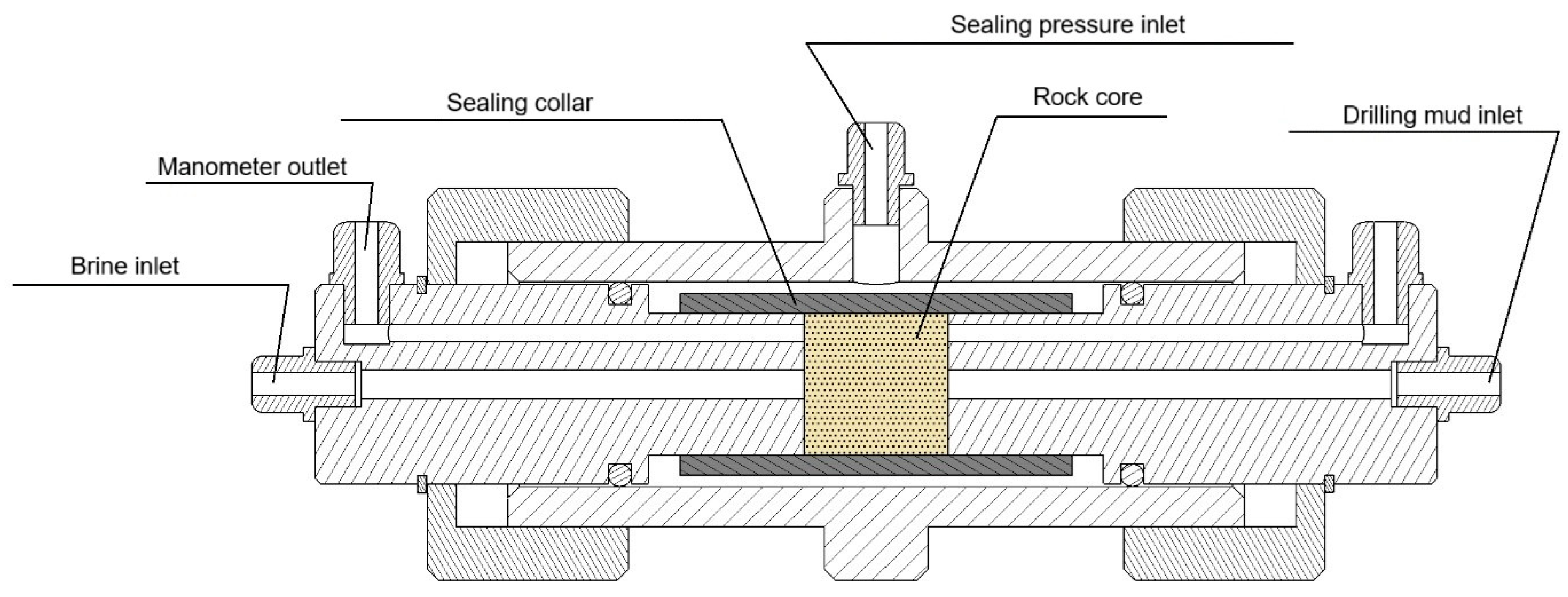
Pore Pressure Transmission (PPT) testing was conducted using a specially designed chamber, a cross-section of which is shown in Figure 3. The chamber consists of a steel cylinder, two fixed pistons with the core placed between them, a rubber sealing collar, and fittings allowing connection of 4 mm diameter pressure lines.
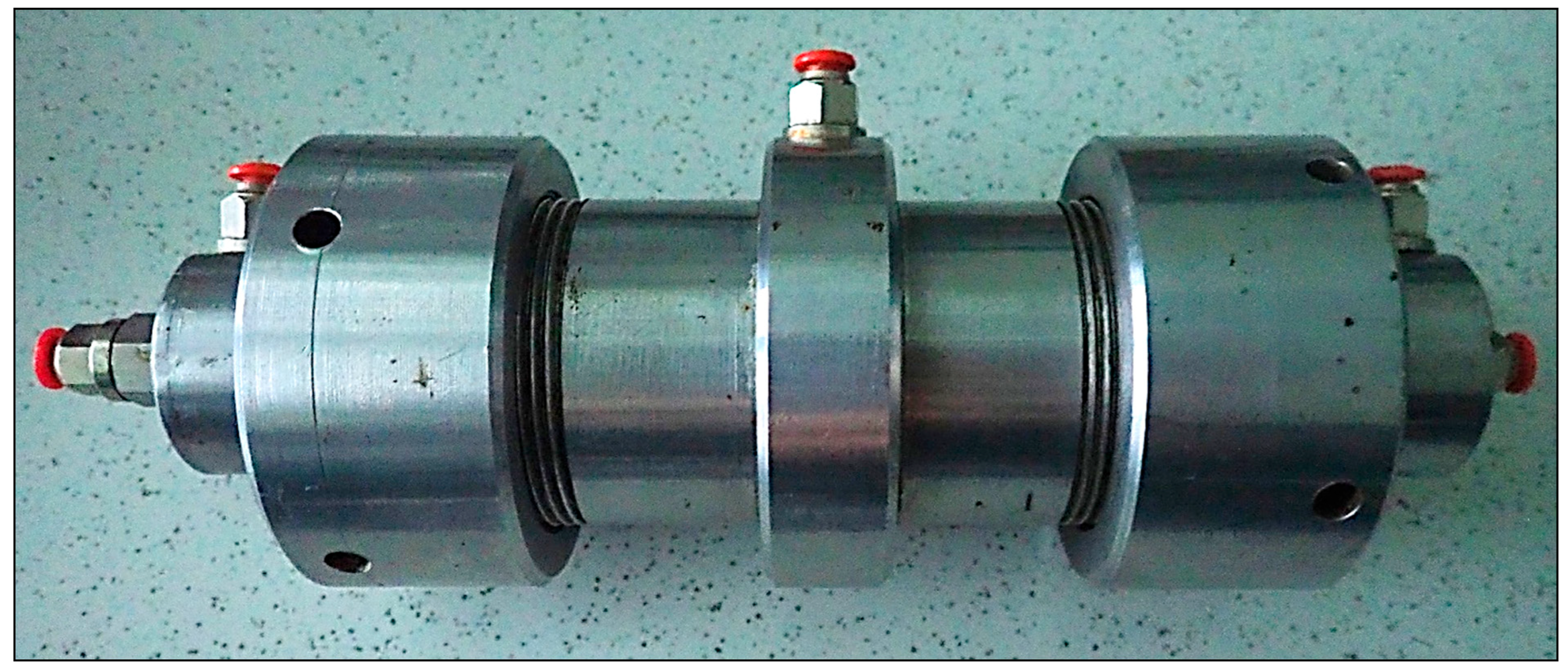
For the test, a core with a diameter of 2.54 cm and a length of 2.54 cm was initially saturated with a 5.0% KCl solution. The core was then placed in the sealing collar, pistons were pressed from both sides, and the assembly was tightly fastened. Air at a pressure of 25 bar was injected into the space between the chamber wall and the sealing collar, causing the collar to clamp tightly around the core and pistons, preventing fluid flow outside the core. The first piston was connected via pressure lines to a formation brine reservoir, and the second to a reservoir with the tested drilling fluid. Pressure was applied so that formation brine was injected into the core from one side at 2 bar, while the tested drilling fluid was injected from the other side at 18 bar. An electronic manometer connected to the piston on the formation brine side measured the pore pressure in the tested core, and the increase in pressure is referred to as pore pressure penetration. Manometer readings were recorded at 1 min intervals at the start, then at 5, 15, and 30 min intervals, with the total measurement lasting 48 h. The chamber is shown in Figure 4.

2.3. Raw Materials

For the laboratory tests, natural and semi-synthetic polymers used in drilling fluid technology and agents serving as bridging materials were applied. Materials used are as follows:
  • Modified carboxymethylcellulose (CMC) is obtained in the process of etherification of wood cellulose with monochloroacetic acid. It is used to reduce filtration and increase the viscosity of water-based drilling fluids.
    Polyanionic cellulose (PAC), described as highly purified carboxymethylcellulose, is primarily used to control the filtration and viscosity of drilling fluids and can be applied in the chemical treatment of all types of water-based dispersible drilling fluids. Two versions of the agent were used in the study: low-viscosity (LV) and medium-viscosity (R).
  • The biopolymer XCD is obtained by the action of bacteria of the Xanthomonas campestris genus on glucose. Fermentation produces a polysaccharide known as xanthan gum. This agent dissolves easily in fresh water, seawater, as well as in solutions of various salts at any concentration. XCD can be dissolved in liquids with a pH range of 3 to 12 and primarily provides the required rheological properties to drilling fluids.
  • Gelatinized starch. Natural starch does not dissolve in cold water and therefore undergoes chemical treatment. To make it water-soluble and capable of forming a colloidal solution, starch is modified through thermal gelatinization, usually in the presence of suitable chemicals. During gelatinization, the outer amylopectin layer breaks down, releasing the amylose contained inside.
  • Potassium chloride—used as a clay-rock hydration inhibitor.
  • Sodium hydroxide solution—used as a pH regulator for drilling fluids.
  • Carbonate blocker—ground marble, used in drilling fluids both to reduce filtration and as a weighting material. Due to its high solubility in hydrochloric acid, it is mainly used for weighting drilling fluids intended for reservoir re-drilling, various working fluids, primarily brines, used in well completion and reconstruction, and for preparing packer fluids.
  • Organic blocker—an innovative agent was used, with grains made of specially treated cellulose, giving them high strength and elasticity, enabling the formation of a tight and durable filter cake on the borehole wall. This agent comes in several types depending on grain size:
    -
    Grain diameter up to 150 µm—referred to as OB1 (Organic Blocker 1);
    -
    Grain diameter up to 250 µm—referred to as OB2 (Organic Blocker 2);
    -
    Grain diameter from 150 to 500 µm—referred to as OB3 (Organic Blocker 3).
For laboratory tests aimed at measuring pore pressure transmission, sandstone was collected from a depth of approximately 300 to 400 m from a construction sandstone reservoir. According to information from the producer, this sandstone deposit is located in the upper part of the lower Istebnia layers. These layers mainly consist of thick-bedded, massive fine- and medium-grained sandstones with clay–limestone binder and subordinate interbeds of shales. Above and below the sandstone complex are layers of the Innoceramus facies, predominantly shale.

3. Results

The drilling fluid used in the study had to exhibit sufficiently high rheological and structural parameters so that its structure remained stable after the addition of blocking agents, and the agents did not undergo sedimentation. It was anticipated that, due to the largest particle size, the most difficult agent to suspend in the drilling fluid would be OB3.
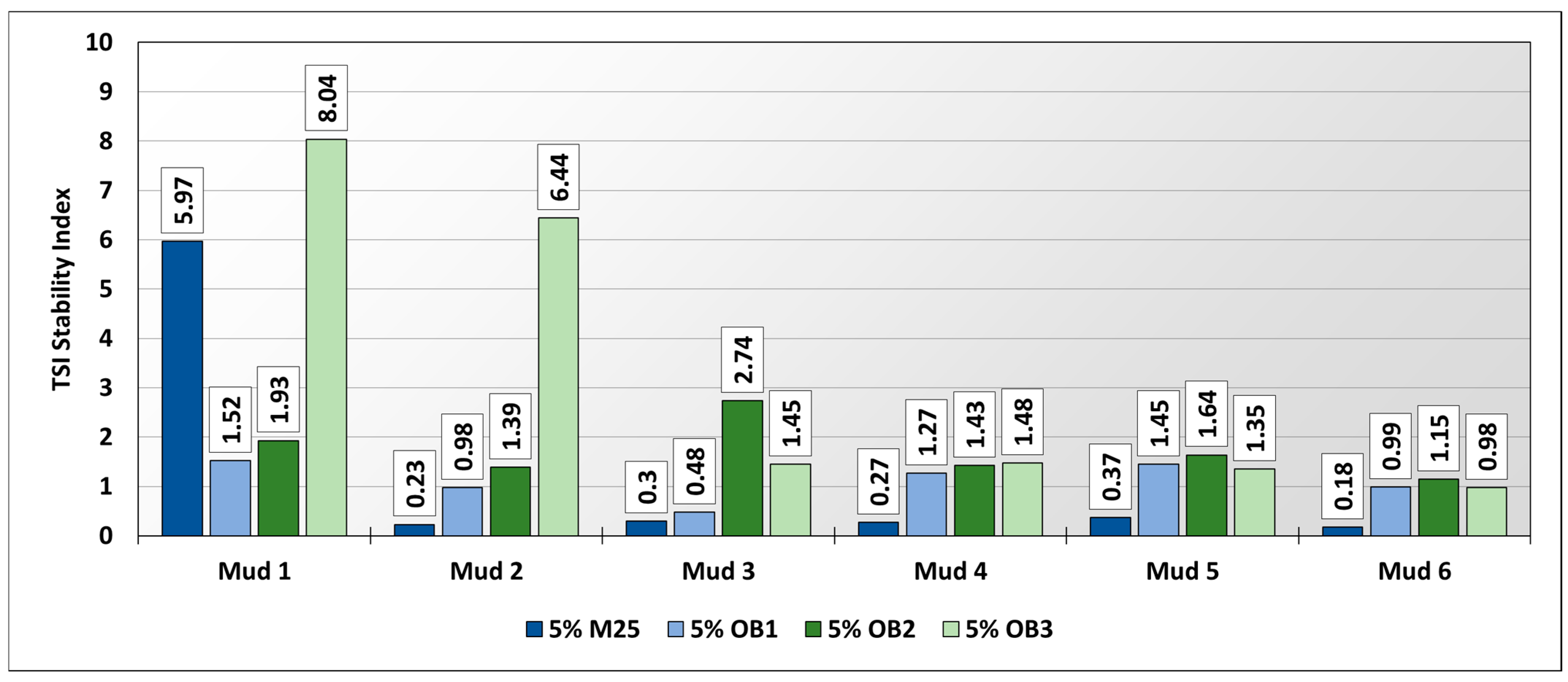
The Turbiscan Tower apparatus, which allows real-time monitoring of the stability of up to six samples simultaneously, was used to develop the optimal drilling fluid composition. The measurement was carried out at 25 °C over a period of 24 h. The stability of the drilling fluid was assessed using the Turbiscan Stability Index (TSI). This is a dimensionless coefficient automatically calculated for each tested sample by the apparatus, allowing for a simple assessment of the global instability of the tested liquid. It was assumed that a stable liquid, not undergoing phenomena such as sedimentation or creaming, should be characterized by a TSI lower than 1.
In the course of the study, six drilling fluid formulations were tested, differing in the content of structural polymers, mainly XCD biopolymer, the concentration of which was 0.2% in drilling fluid 1 and 0.35% in drilling fluid 6 (Table 1). Selected bridging agents were added to each of the prepared drilling fluids at a concentration of 5.0%. Based on the obtained TSI values, it was evaluated which drilling fluid composition ensured the highest stability and the lowest risk of sedimentation.
Figure 5 presents the TSI values of all tested drilling fluids after 24 h of measurement. As expected, the highest TSI stability index values were recorded in drilling fluids with the lowest rheological and structural parameters, namely drilling fluids 1 and 2. These fluids, particularly when combined with the bridging agent OB3, showed a very low level of stability: 8.04 for drilling fluid 1 and 6.44 for drilling fluid 2. This result was most likely due to the largest average grain size of this blocking agent. It is clearly visible that with the increase in the concentration of structural polymers, and consequently in viscosity, yield point and structural strength in the subsequently prepared drilling fluids, their stability after the addition of blocking agents was increasingly higher. The best results were obtained during the measurements of drilling fluid 6, where, in the case of three out of the four applied bridging agents (M25, OB1 and OB3), TSI < 1 was achieved (0.18, 0.99 and 0.98, respectively), while for one agent (OB2), the TSI value slightly exceeded 1 (1.15). Therefore, drilling fluid 6 was selected for further studies as the base fluid.
In the next stage of the research, the effect of the addition of organic blocking agents on the basic parameters of the drilling fluid was determined, i.e., rheological and structural parameters (plastic viscosity, apparent viscosity, yield point, structural strength), density and filtration. This last parameter was particularly important, since by comparing the obtained filtration values, it was possible to determine which drilling fluid formulations allowed the most impermeable filter cake to be formed. The base drilling fluid was supplemented with blockers OB1, OB2, and OB3 at concentrations of 1.0%, 3.0%, and 5.0%. The results obtained are presented in Table 2.
It can be observed that, in addition to the bridging material, sodium hydroxide was also added to each formulation. This was necessary to raise the pH of the drilling fluids, as the addition of organic blockers caused a marked decrease in their pH level.
The obtained measurement results showed that modifying the composition of the drilling fluid with organic blockers had only a minor effect on the values of the rheological-structural parameters. The greatest changes occurred when OB1 was added to the base drilling fluid at a concentration of 5.0%. The value of plastic viscosity increased by about 14% (from 43 to 49 mPa·s), apparent viscosity by about 6% (from 72.5 to 76.5 mPa·s), while the yield point decreased by about 7% (from 28.2 to 26.3 Pa).
Much greater differences were recorded in the case of filtration values of the drilling fluids (Figure 6). All of the applied organic blockers reduced filtration values, with OB1 and OB2 being far more effective than OB3, which is characterized by the largest grain size.
With the addition of OB1 at a concentration of 1.0%, the filtration value decreased from 10.2 cm3 for the base drilling fluid to 6.6 cm3, i.e., by about 35%. When the concentration of OB1 was increased to 3.0%, the filtration value dropped to 5.8 cm3, i.e., about 43% lower than for the base fluid, while at a 5.0% concentration, filtration was 4.2 cm3, i.e., about 59% lower than the base fluid. OB2 proved to be somewhat less effective, with filtration values of 7.4 cm3, 6.0 cm3, and 4.8 cm3 for concentrations of 1.0%, 3.0%, and 5.0%, respectively.
On the basis of the obtained results, further research on OB3 was abandoned due to its much lower efficiency in forming a tight filter cake compared to OB1 and OB2. The large grain sizes of this material make it more suitable as a means of preventing losses rather than as a typical material limiting damage to the near-wellbore zone.
The next stage of the research involved determining the parameters of drilling fluids modified by adding a combination of two bridging materials. These pairs were formed from the following agents:
  • Blocker M25;
  • OB1;
  • OB2.
The first combination tested was the mixture of carbonate blocker M25 and organic blocker OB1. In all drilling fluids, the values of rheological-structural parameters were similar, slightly higher than in the base fluid. The pH value of the obtained drilling fluids was adjusted by adding sodium hydroxide and remained in the range of 9.2–9.3. All measured parameters are presented in Table 3.
The next set of blockers modifying the base drilling fluid was the combination of M25 and OB2. The rheological-structural parameters of these fluids were fairly stable, with slightly higher values recorded in the samples with 4.0% M25 + 1.0% OB2 and 2.0% M25 + 3.0% OB2. The pH value, regulated with sodium hydroxide, ranged between 9.3 and 9.4 (Table 4).
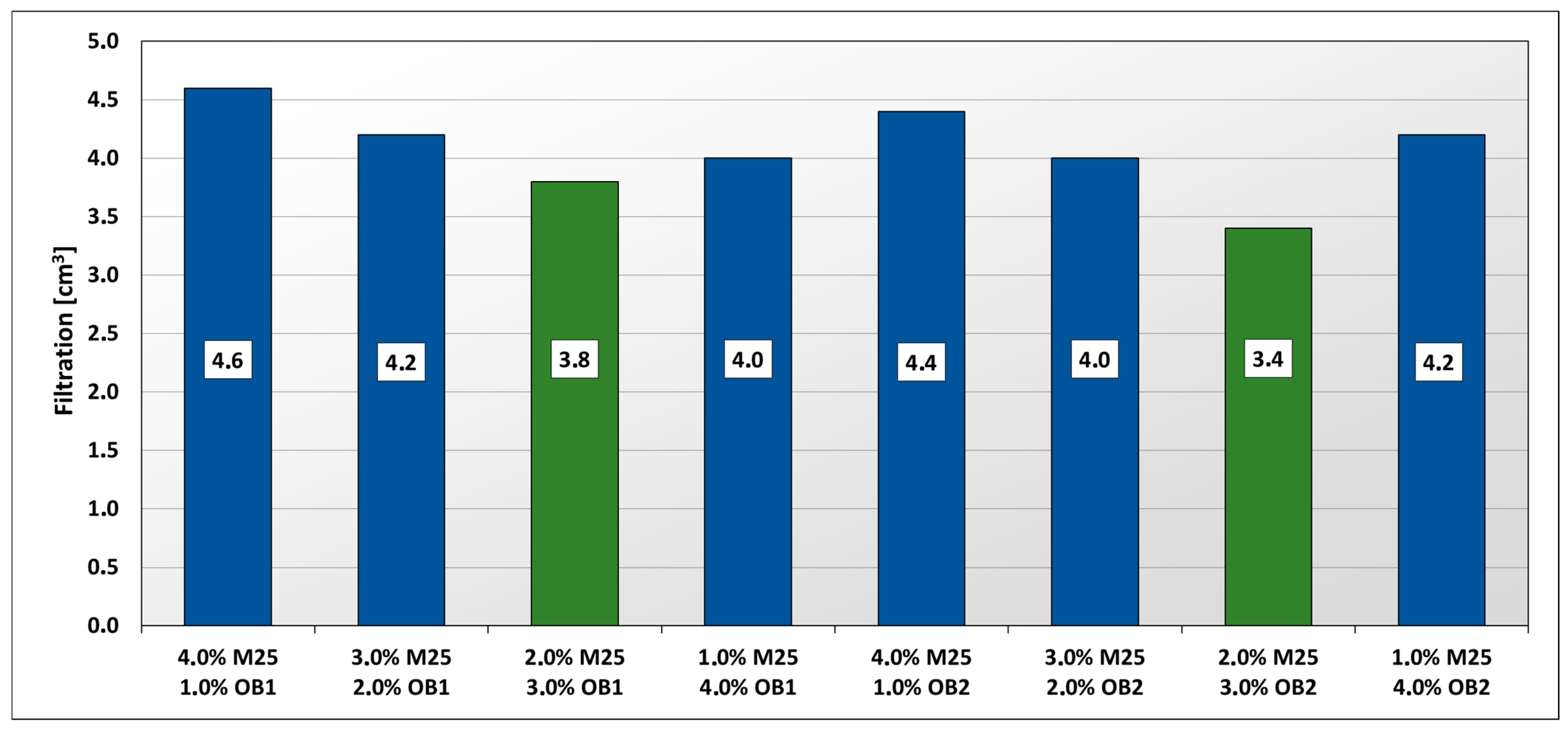
Figure 7 presents the filtration values of all drilling fluids with a double set of blockers. The highest filtration was observed in fluids modified with the sets 4.0% M25 + 1.0% OB1 (4.6 cm3) and 4.0% M25 + 1.0% OB2 (4.4 cm3). The lowest measurement results were obtained for the combinations 2.0% M25 + 3.0% OB1 (3.8 cm3) and 2.0% M25 + 3.0% OB2 (3.4 cm3).
From among the drilling fluids tested with a double set of blocking agents, two were selected for further research, namely for pore pressure transmission measurement (marked with green bars in Figure 6).
The final stage of the study was the measurement of pore pressure transmission. The measurement was carried out on six drilling fluids:
  • Base drilling fluid,
  • Drilling fluid containing 5.0% of the M25 blocking agent;
  • Drilling fluid containing 5.0% of the OB1 blocking agent;
  • Drilling fluid containing 5.0% of the OB2 blocking agent;
  • Drilling fluid with the 2.0% M25 + 3.0% OB1 set of blocking agents;
  • Drilling fluid with the 2.0% M25 + 3.0% OB2 set of blocking agents.
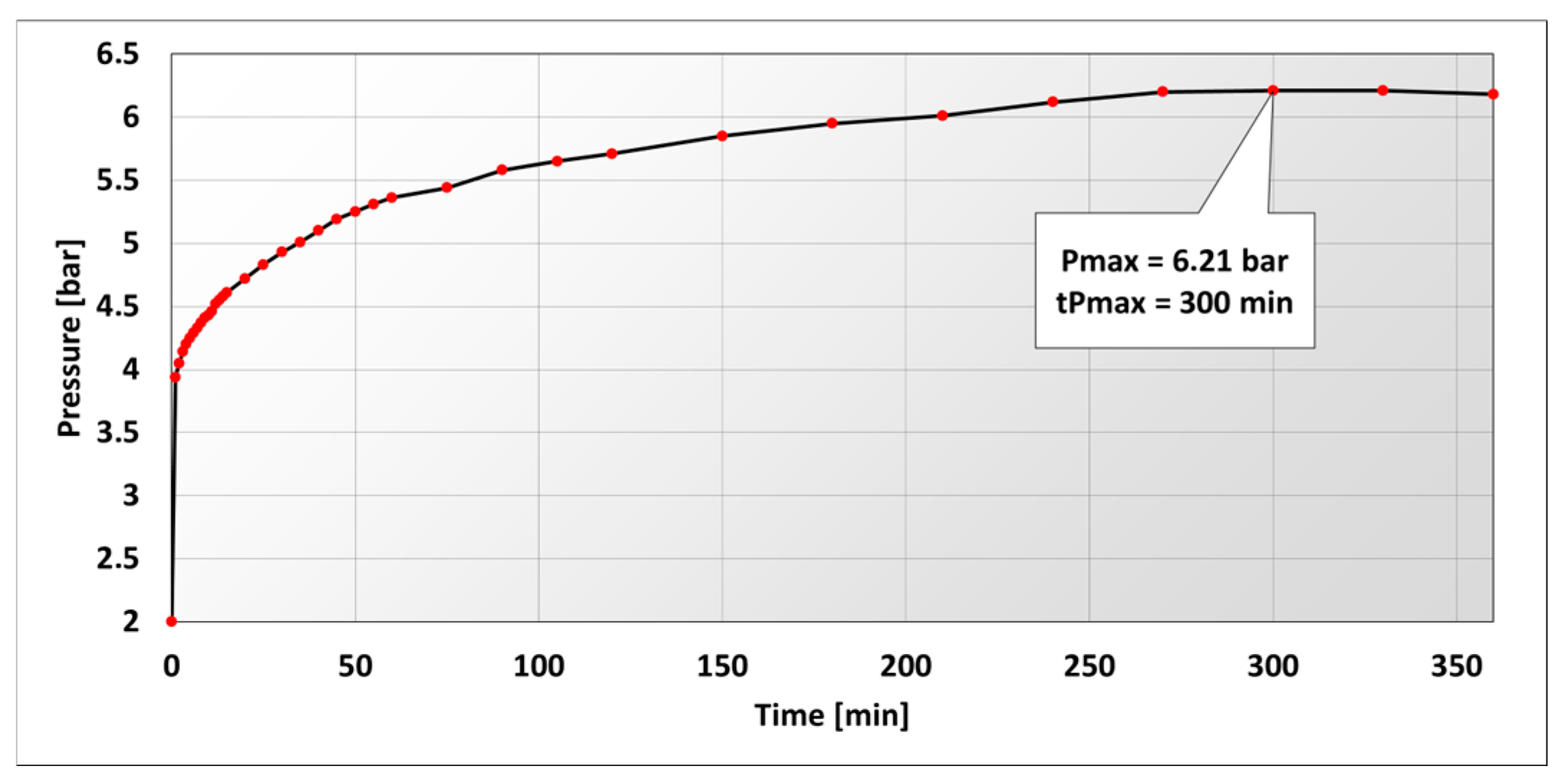
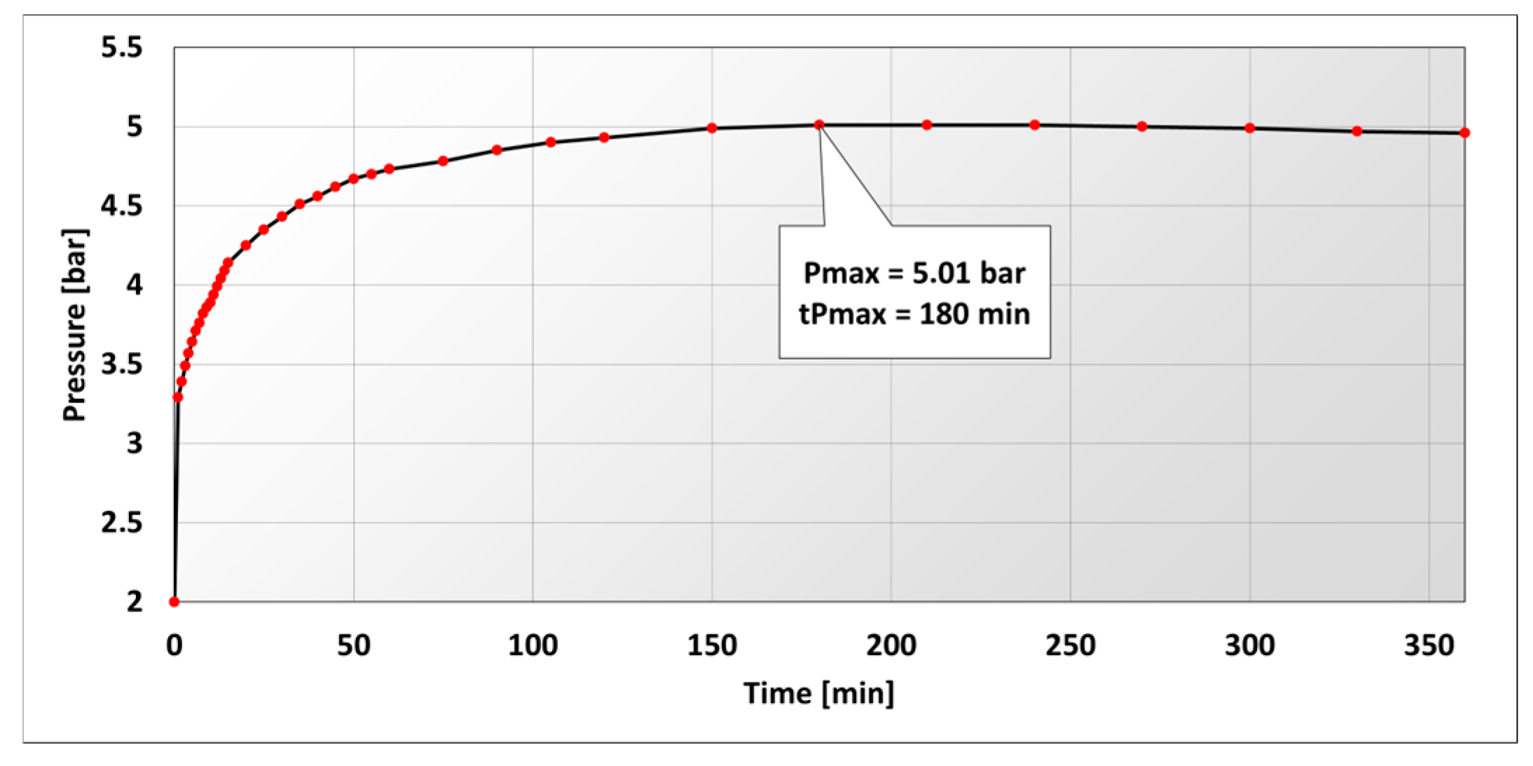
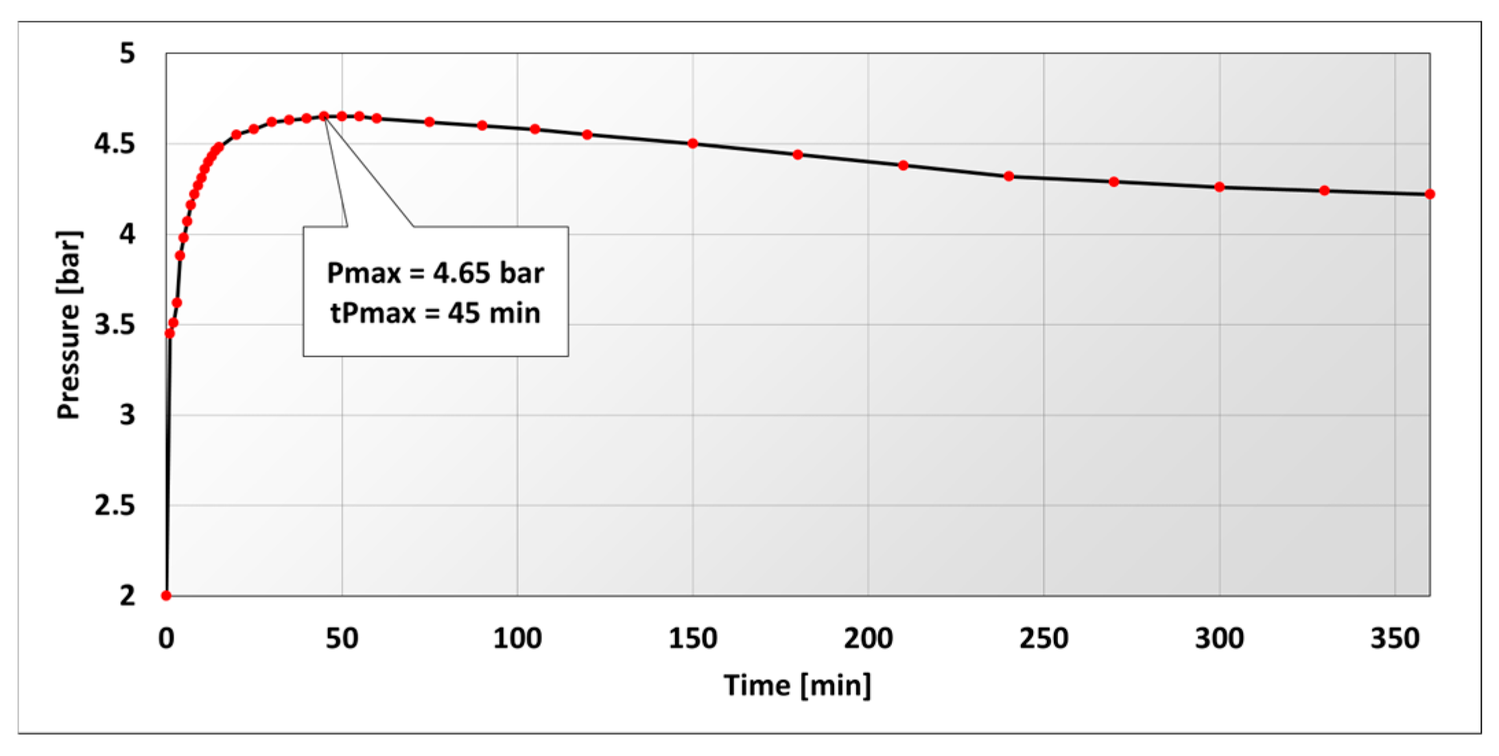
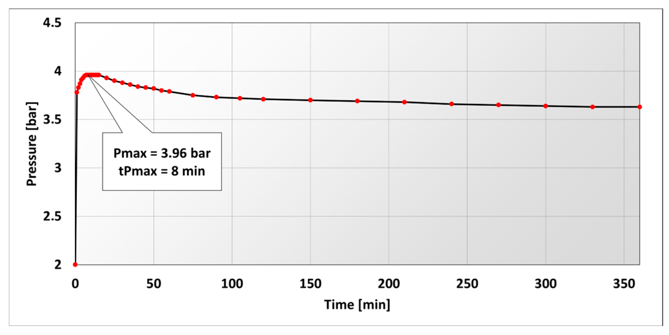
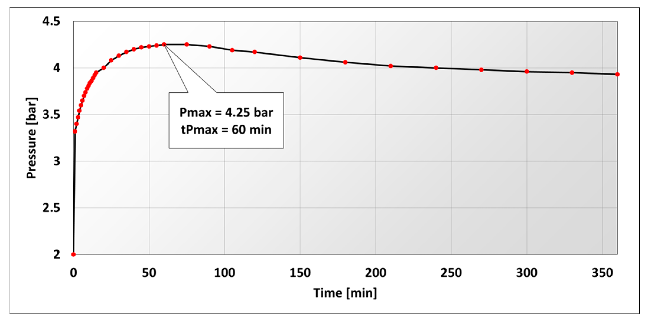
The PPT measurement was performed using cores cut from sandstone, with the formation brine pressure set at 2 bar and the drilling fluid pressure at 18 bar. As a result of the test, a graph was obtained showing the value of the pore pressure of the core as a function of time. From the results obtained, parameters such as the maximum pressure (denoted as pmax) and the time after which the maximum pressure was reached (denoted as tpmax) could be read. The results of the tests are presented in Figure 8, Figure 9, Figure 10, Figure 11, Figure 12 and Figure 13.
The initial pressure measured in all tests was equal to the set formation brine pressure, i.e., 2 bar. After applying the drilling fluid pressure (18 bar) from the opposite side of the core, a gradual increase in pore pressure began, resulting from the penetration of filtrate into the rock pores under a pressure higher than that of the formation brine. After a certain period, characteristic for each type of drilling fluid tested, the pore pressure reached its maximum value, followed by a phase of pressure decline and then stabilization, with this phase being much longer than the pressure build-up stage. The duration of the pressure build-up phase, as well as the maximum pressure value, can be linked both to the rate of filter cake formation and to its impermeability. A drilling fluid in which the bridging agent has been properly selected in terms of grain size and concentration is capable of producing a good-quality filter cake more quickly than a fluid with an improperly selected blocking agent. The fastest possible formation of filter cake is extremely important from the perspective of protecting the near-wellbore zone, as it largely determines how much filtrate volume will invade the rock pores.
The results of the pore pressure transmission measurement are presented in Table 5. A significant variation in results can be observed depending on the composition of the tested drilling fluids. The base drilling fluid, which did not contain any blocking agent in its composition, showed the highest maximum pressure (pmax = 6.21 bar) and the longest tpmax time, equal to 300 min. This indicates the lowest ability to quickly form a filter cake among all tested samples. The low effectiveness of this sample was also confirmed at the end of the test, when the presence of filtrate was found in the brine tank, meaning that it managed to penetrate through the entire pore volume of the core as well as the supply lines.
Next, three drilling fluids with the addition of a single blocker were tested. These were 5.0% concentrations of M25, OB1, and OB2 agents. Significantly better results were observed compared to the base fluid, particularly for the fluid with the addition of OB2. The maximum pressure, pmax, reached 4.65 bar, and the pressure buildup time was 45 min.
The most effective in terms of quickly forming a sealing filter cake was the fluid with a combination of two bridging materials: the 2.0% M25 blocker and the 3.0% OB1 blocker. The very low-pressure buildup time of 8 min and low maximum pressure of 3.96 bar suggest that filtrate penetration into the rock pores was minimal. This is also confirmed by the earlier filtration measurement of 3.8 cm3.

4. Conclusions

The aim of this study was to conduct experimental research to develop a drilling fluid composition containing a new type of organic blocker, capable of quickly forming a filter cake that prevents the filtrate from penetrating reservoir rocks. Ensuring a tight barrier on the surface of drilled rocks is particularly important to reduce adverse effects such as the blockage of pore channels by the solid phase from the drilling fluid, the effect of the aqueous phase on clay binders in rocks, pore blockage by the liquid phase, or the precipitation of insoluble deposits when the filtrate comes into contact with mineralized formation water.
During the research, the technological parameters of drilling mud were determined, including density, rheological parameters, API filtration, and pH. The key criterion for assessing the effectiveness of a given mud in sealing the borehole wall was tpmax—the time to reach maximum pressure in the PPT test. This parameter indicates the rate at which a given mud produces a tight filter cake.
On the basis of the analysis of the research carried out during the study, the following conclusions can be drawn:
  • Not all bridging materials selected in the first stage were suitable for use due to their inadequate physical properties. The organic blocker OB3 had significantly larger particle sizes than the other agents used (its grain diameter reached up to 0.5 mm), which resulted in filtration measurement values much higher than those of samples with other blockers. The large grain sizes of this material make it more suitable as a means of preventing losses rather than as a typical material limiting damage to the near-wellbore zone.
  • The rheological and structural properties of the developed base fluid were sufficient to maintain structural stability after the addition of all types of blocking agents. The TSI coefficient was below 1 in three cases, while for one agent (OB2), it was slightly higher.
  • The most effective agent in terms of limiting API filtration of the drilling fluid was OB1. At a concentration of 5.0% of this agent in the drilling fluid, the filtration value was 4.2 cm3. The highest filtration value among the drilling fluids treated with a single blocker was observed for the one modified with the OB3 agent.
  • Among the tested drilling fluids with a double set of blockers, the highest efficiency for reducing filtration values was shown by the following combinations: 2.0% M25 + 3.0% OB1 and 2.0% M25 + 3.0% OB2, with the obtained results being 3.8 cm3 and 3.4 cm3, respectively.
  • The results obtained during the pore pressure transmission test confirmed the results achieved during the API filtration measurement. The base drilling fluid, which exhibited the highest filtration value (10.2 cm3), also had the highest maximum pore pressure (pmax = 6.21 bar) and the longest tpmax duration (300 s). In turn, the drilling fluids with a double set of blockers, which had the lowest filtration values, demonstrated the ability to quickly form a tight filter cake. For example, the fluid with the M25 + OB1 blocker set had a maximum pore pressure of 3.96 bar and a tpmax of 8 min, while the fluid with the M25 + OB2 set had pmax = 4.25 bar and tpmax = 45 min.
  • The conducted tests allowed us to conclude that drilling fluids containing double sets of blocking materials with different particle sizes enabled the formation of a tighter filter cake that prevented filtrate invasion into the reservoir rock compared to fluids with a single bridging agent. This is exhibited both by the API filtration measurement results and the pore pressure transmission test. It also confirms the theory that to quickly create a filter cake sealing the rock, a wide range of blocker particle sizes should be used. Particularly good results were shown by the fluid containing the following combination: carbonate blocker M25 at a 2.0% concentration and organic blocker OB1 at a 3.0% concentration. It can be concluded that a fluid of such composition would effectively prevent the invasion of the solid phase and filtrate into the rock pore space.

Future Work

The research presented in this article used potassium mud, which, due to its ability to inhibit hydration, is used for drilling shale formations. The drilling industry also uses mud with other mechanisms that prevent the hydration of clay minerals. These include mud with the addition of polyglycol, latex, or amines. Therefore, it is planned to extend this research on the use of innovative organic blockers to other types of mud, such as glycol mud and amine mud.

Author Contributions

Conceptualization, G.Z., S.B. and B.J.; methodology, G.Z. and B.J.; validation, G.Z., S.B. and B.J.; formal analysis, G.Z. and S.B.; investigation, G.Z. and B.J.; resources, G.Z. and S.B.; data curation, G.Z. and B.J.; writing—original draft preparation, G.Z. and B.J.; writing—review and editing, B.J. and S.B.; visualization, G.Z. and B.J.; supervision, G.Z.; project administration, G.Z. and S.B. All authors have read and agreed to the published version of the manuscript.

Funding

This article was prepared based on a statutory study entitled: Preventing Filtrate Invasion into the Drilled Formation Using an Organic Blocking Material, a study by the Oil and Gas Institute–National Research Institute commissioned by the Ministry of Science and Higher Education; order number: 0056/KW/2023, archive number: DK-4100-0039/2023.

Institutional Review Board Statement

Not applicable.

Informed Consent Statement

Not applicable.

Data Availability Statement

The data presented in this study are available on request from the corresponding author due to company policy.

Conflicts of Interest

The authors declare no conflicts of interest.

References

  1. Elmgerbi, A.; Les, B.; Ashena, R.; Atkin, T. A Practical Decision Tool to Evaluate and Rank Potential Solutions for Expected Downhole Drilling Problems During the Well-planning Phase. J. Inst. Eng. India Ser. D 2022, 103, 25–36. [Google Scholar] [CrossRef]
  2. Gholami, R.; Elochukwu, H.; Fakhari, N.; Sarmadivaleh, M. A review on borehole instability in active shale formations: Interactions, mechanisms and inhibitors. Earth-Sci. Rev. 2018, 177, 2–13. [Google Scholar] [CrossRef]
  3. Plumb, R. Influence of Composition and Texture on the Failure Properties of Clastic Rocks. Eurock 1994, 94, 13–20. [Google Scholar] [CrossRef]
  4. Pedrosa, C.; Saasen, A.; Ytrehus, J.D. Hole cleaning and wet-granular rheology of rock cutting beds: Impact of drilling fluid composition. J. Pet. Sci. Eng. 2023, 220 Pt. B, 111267. [Google Scholar] [CrossRef]
  5. Panevnik, D.A.; Velichkovich, A.S. Assessment of the stressed state of the casing of the above-bit hydroelevator. Oil Ind. J. 2017, 1, 70–73. [Google Scholar]
  6. Velichkovich, A.S.; Panevnik, D.A. Study of the stress state of the downhole jet pump housing. Nauk. Visnyk Natsionalnoho Hirnychoho Universytetu 2017, 5, 50–55. [Google Scholar]
  7. Alvarez, L.A.; Cedeno, M.D.; Villon, P.V.; Pinoargote, R.C. Design of a fluid for workover operations in the Gustavo Galindo Oilfield, Ecuador. ARPN J. Eng. Appl. Sci. 2019, 14, 2118–2124. [Google Scholar]
  8. Caenn, R.; Darley, H.C.H.; Gray, G.R. Composition and Properties of Drilling and Completion Fluids, 6th ed.; Gulf Professional Publishing: Houston, TX, USA, 2011. [Google Scholar]
  9. Mungan, N. Permeability reduction through changes in pH and salinity. SPE-1283-PA. J. Pet. Technol. 1965, 17, 1449–1453. [Google Scholar] [CrossRef]
  10. Rahman, S.S.; Rahman, M.M.; Khan, F.A. Response of low-permeability, illitic sandstone to drilling and completion fluids. J. Petrol. Sci. Eng. 1995, 12, 309–322. [Google Scholar] [CrossRef]
  11. Stec, M. Opracowanie Nowych Receptur PłUczek Mrówczanowych W Aspekcie Ograniczenia Uszkodzenia Strefy Przyodwiertowej. Ph. D. Thesis, Rozprawa Doktorska, Akademia Górniczo-Hutnicza, Kraków, Poland, 2017. [Google Scholar]
  12. Uliasz, M. Ciecze Robocze—Ich Właściwości Technologiczne i Rola w Procesie Rekonstrukcji Odwiertów; Instytut Nafty i Gazu—Państwowy Instytut Badawczy: Kraków, Poland, 2021; p. 235. [Google Scholar] [CrossRef]
  13. van Oort, E. On the physical and chemical stability of shales. J. Petrol. Sci. Eng. 2003, 38, 213–235. [Google Scholar] [CrossRef]
  14. Fleming, N.; Moldrheim, E.; Teigland, E.; Mathisen, A.-M. Systematic Approach to Well Productivity Evaluation to Determine the Significance of Formation Damage for Wells Drilled in a Depleted Reservoir Without Bridging Particles: Oseberg Main Case History. SPE Prod. Oper. 2020, 35, 681–690. [Google Scholar] [CrossRef]
  15. Bageri, B.S.; Mahmoud, M.A.; Al-Mutairi, S.H.; Kuwait, C.; Abdulraheem, A. Filter Cake Porosity and Permeability Profile Along the Horizontal Well and Their Impact on Filter Cake Removal. In Proceedings of the International Petroleum Technology Conference, Doha, Qatar, 6–9 December 2015. [Google Scholar] [CrossRef]
  16. Feng, Y.; Li, G.; Meng, Y.; Guo, B. A Novel Approach to Investigating Transport of Lost Circulation Materials in Rough Fracture. Energies 2018, 11, 2572. [Google Scholar] [CrossRef]
  17. Jinhua, H.; Xing, Z.; Yuanjun, C.; Baisong, Y.; Jian, Z.; Xuemin, W.; Wei, L.; Zhansheng, W.; Ruizhi, Z. Preparation, characterization and application of environment-friendly high density and low damage solid free completion fluids for completing HTHP oil and gas wells. Geoenergy Sci. Eng. 2023, 221, 211351. [Google Scholar] [CrossRef]
  18. Chen, L.; Huang, F.; Li, G.; Mao, Z.; Hu, Y.; Liu, L.; Zeng, H.; Xu, S. Experimental Study on Fiber Balls for Bridging in Fractured-Vuggy Reservoir. SPE J. 2023, 28, 1880–1894. [Google Scholar] [CrossRef]
  19. Li, Z.; Zhou, Y.; Qu, L.; Wang, Y.; Zhang, S. A New Method for Designing the Bridging Particle Size Distribution for Fractured Carbonate Reservoirs. SPE J. 2023, 27, 2552–2562. [Google Scholar] [CrossRef]
  20. Rad, M.S.K.; Mohammadi, M.K.; Nowtarki, K.T. Bridging Agents Optimization Based on Predicting Induced Fracture Model for Deviated Wells—A Case Study. In Proceedings of the IADC/SPE Asia Pacific Drilling Technology Conference, Virtual, 8–9 June 2021. [Google Scholar] [CrossRef]
  21. Li, X.; Zheng, L.; Chen, Y.; Huang, X.; Zhai, X.; Wei, P.; Tao, X.; Nie, S. Fuzzy-Ball Fluids Enhance the Production of Oil and Gas Wells: A Historical Review. Energies 2023, 16, 6647. [Google Scholar] [CrossRef]
  22. Available online: http://bdc.com.pl (accessed on 14 August 2025).
  23. Available online: http://www.glossary.oilfield.slb.com (accessed on 20 August 2025).
  24. Available online: http://www.pspw-krosno.com.pl (accessed on 14 August 2025).
  25. Jasiński, B. Określenie dynamicznej filtracji płuczek wiertniczych w warunkach HPHT z użyciem nowatorskiej metody pomiarowej. Naft.-Gaz 2018, 2, 85–95. [Google Scholar] [CrossRef]
  26. Han, Y.; Luo, B.; Chang, F.; Li, W. Numerical Investigation of Particle Bridging Near Fracture Entrance. In Proceedings of the 56th U.S. Rock Mechanics/Geomechanics Symposium, Santa Fe, NM, USA, 26–29 June 2022. [Google Scholar] [CrossRef]
  27. Popov, S.V.; Nikitin, P.M.; Udaltsov, D.A.; Ryabtsev, P.L. Smart Bridging Agent—Prevents Formation Damage and Removed with Formation Fluid. In Proceedings of the SPE Russian Petroleum Technology Conference, Virtual, 26–29 October 2020. [Google Scholar] [CrossRef]
  28. Uliasz, M.; Herman, Z. Wymagania i właściwości cieczy roboczych. In Proceedings of the Konferencja z okazji 20-lecia Instytutu Problemów Nafty i Gazu Rosyjskiej Akademii Nauk, Moscow, Russia, 24–26 April 2007. [Google Scholar]
  29. Uliasz, M.; Herman, Z. Wymagane parametry cieczy roboczych dla ochrony pierwotnych właściwości skał zbiornikowych. Wiert.-Naft.-Gaz 2008, 25, 753–764. [Google Scholar]
  30. Abiodun, S.; Vincent, J.M.; Schultz, K.; Rapp, E. Using Particle Size Theories to Optimize Bridging Solids for Post-Gravel-Pack Screens. In Proceedings of the SPE International Conference and Exhibition on Formation Damage Control, Lafayette, LA, USA, 12 February 2020. [Google Scholar] [CrossRef]
  31. Izyurov, V.; Kharitonov, A.; Semenikhin, I.; Korsunov, E.; Gassan, A.; Tikhonov, E.; Jadan, G.; Stashko, V.; Blagonadeshniy, I.; Manikhin, A.; et al. Selecting Bridging Agents’ Particle Size Distribution for Optimum Plugging While Drilling in Permeable Zones. In Proceedings of the SPE Russian Petroleum Technology Conference, Moscow, Russia, 22–24 October 2019. [Google Scholar] [CrossRef]
  32. Abdo, J.; Haneef, M.D. Nano-enhanced drilling fluids: Pioneering approach to overcome uncompromising drilling problems. J. Energy Resour. Technol. 2012, 134, 014501. [Google Scholar] [CrossRef]
  33. Abdo, J.; Haneef, M.D. Clay nanoparticles modified drilling fluids for drilling of deep hydrocarbon wells. Appl. Clay Sci. 2016, 86, 76–82. [Google Scholar] [CrossRef]
  34. Zima, G. Analiza wpływu nanomateriałów na właściwości osadu filtracyjnego. Naft.-Gaz 2017, 5, 312–320. [Google Scholar] [CrossRef]
  35. Mohamed, Y.A.; Ahmed, R.S.; El-Agamy, H.A.; Kheir, M.M.; Ahmed, S.S.; Hassan, S.H.; Hady, A.S.A.; Al-Zahry, A.A.E.; Salama, A.M.; Gaber, L.A.; et al. Innovative Polymeric Nanoparticles Associated with Engineered Bridging Particles Solve Depleted Reservoir Drilling Challenges (Case study: Gulf of Suez). In Proceedings of the Gas & Oil Technology Showcase and Conference, Dubai, United Arab Emirates, 13–15 March 2023. [Google Scholar] [CrossRef]
  36. Alia, U.; Latif, A.; Chong, Z.N.; Chong, K.I.; Belhaj, H.; Al Hameli, F. Smart Nano Clay to Reduce Water-Based Mud Filter Cake. In Proceedings of the ADIPEC, Abu Dhabi, United Arab Emirates, 31 October–3 November 2022. [Google Scholar] [CrossRef]
  37. Dębińska, E. Wpływ nanokrzemionki na parametry mechaniczne kamienia cementowego. Naft.-Gaz 2014, 4, 229–235. [Google Scholar]
  38. Dębińska, E. Niekonwencjonalne zaczyny cementowe z dodatkiem nanokrzemionki. Naft.-Gaz 2015, 5, 290–300. [Google Scholar]
  39. Jankiewicz, B.J.; Choma, J.; Jamioła, D.; Jaroniec, M. Nanostruktury krzemionkowo-metaliczne. Otrzymywanie i modyfikacja nanocząstek krzemionkowych. Wiadomości Chem. 2010, 64, 913–942. [Google Scholar]
  40. Alvi, M.A.A.; Belayneh, M.; Bandyopadhyay, S.; Minde, M.W. Effect of Iron Oxide Nanoparticles on the Properties of Water-Based Drilling Fluids. Energies 2020, 13, 6718. [Google Scholar] [CrossRef]
  41. Adel, M.; Ragab, S.; Noah, A. Reduction of formation damage and fluid loss using nano-sized silica drilling fluids. Pet. Technol. Dev. J. Int. J. 2014, 2, 75–88. [Google Scholar]
  42. Contreras, O.; Hareland, G.; Husein, M.; Nygaard, R.; Al-Saba, M. Application of in-house prepared nanoparticles as filtration control additive to reduce formation damage. In Proceedings of the SPE International Symposium and Exhibition on Formation Damage Control, Lafayette, LA, USA, 18–20 February 2014. [Google Scholar] [CrossRef]
  43. Ponmani, S.; Nagarajan, R.; Sangwai, J.S. Effect of nanofluids of CuO and ZnO in polyethylene glycol and polyvinylpyrrolidone on the thermal, electrical, and filtration-loss properties of water-based drilling fluids. SPE-178919-PA. SPE J. 2016, 21, 405–415. [Google Scholar] [CrossRef]
  44. Salih, A.H.; Bilgesu, H. Investigation of rheological and filtration properties of water-based drilling fluids using various anionic nanoparticles. SPE-185638-MS. SPE J. 2017, 21, 405–415. [Google Scholar] [CrossRef]
  45. Salih, A.H.; Elshehabi, T.A.; Bilgesu, H.I. Impact of nanomaterials on the rheological and filtration properties of water-based drilling fluids. In Proceedings of the SPE Eastern Regional Meeting, Canton, OH, USA, 13–15 September 2016. [Google Scholar] [CrossRef]
  46. Raczkowski, J.; Półchłopek, T. Materiały i środki chemiczne do sporządzania płuczek wiertniczych. Prace INiG 1998, 95, 1–319. [Google Scholar]
  47. He, Z.; Fan, S.; Fang, J.; Yu, Y.; Zhang, J.; Li, S.; Xu, P. Research and Application of Fast Plugging Method for Fault Zone Formation in Tarim Basin, China. Energies 2023, 16, 4330. [Google Scholar] [CrossRef]
  48. Jia, H.; Chen, H.; Guo, S. Fluid loss control mechanism of using polymer gel pill based on multi-crosslinking during overbalanced well workover and completion. Fuel 2017, 210, 207–216. [Google Scholar] [CrossRef]
  49. Al-Delfi, A.K.; Al-Mahdawi, F.H. A comprehensive review of lost circulation: Principles and treatments. In Proceedings of the AIP Conference Proceeding, Sofia, Bulgaria, 10–16 June 2023; Volume 2839, p. 020026. [Google Scholar] [CrossRef]
  50. Ibrahim, M.A.; Jaafar, M.Z.; Yusof, M.A.M.; Idris, A.K. A review on the effect of nanoparticle in drilling fluid on filtration and formation damage. J. Pet. Sci. Eng. 2022, 217, 110922. [Google Scholar] [CrossRef]
  51. Idress, M.; Hasan, M.L. Investigation of different environmental-friendly waste materials as lost circulation additive in drilling fluids. J. Pet. Explor. Prod. Technol. 2020, 10, 233–242. [Google Scholar] [CrossRef]
  52. Shuvo, M.A.I.; Sultan, M.Z.B.; Ferdous, A.R.R. Applicability of sawdust as a green additive to improve the rheological and filtration properties of water-based drilling fluid: An experimental investigation. J. Pet. Explor. Prod. Technol. 2024, 14, 303–315. [Google Scholar] [CrossRef]
  53. Dike, H.N.; Chibueze, L.N.; Ipinsokan, S.; Adewumi, C.N.; Olabode, O.; Olaniyan, D.D.; Pius, I.E.; Oke, M.A. An Evaluation of the Rheological and Filtration Properties of Cow Bone Powder and Calcium Carbonate as Fluid-Loss Additives in Drilling Operations. Processes 2025, 13, 2205. [Google Scholar] [CrossRef]
Figure 1. Complications caused by poor selection of drilling fluid.
Applsci 15 11601 g001
Figure 2. Diagram of borehole wall sealing by a flexible organic blocker: (a) free movement of blocker particles in the drilling fluid; (b) increasing pressure difference, blocker particles migrate towards the borehole wall; and (c) maximum pressure difference, flexible blocker particles form a tight filter cake on the borehole wall.
Applsci 15 11601 g002
Figure 3. Cross-section of the chamber for conducting the Pore Pressure Transmission Test.
Applsci 15 11601 g003
Figure 4. Chamber for conducting the Pore Pressure Transmission Test.
Applsci 15 11601 g004
Figure 5. TSI values of the tested mud after 24 h.
Applsci 15 11601 g005
Figure 6. Filtration values of the tested mud. The best filtration measurement results (5.0% OB1 and 5.0% OB2) are marked in green.
Applsci 15 11601 g006
Figure 7. Filtration of drilling mud with various combinations of bridging agents. The best filtration measurement results are marked in green.
Applsci 15 11601 g007
Figure 8. PPT test result for base fluid.
Applsci 15 11601 g008
Figure 9. PPT test result for mud with 5.0% carbonate blocker added.
Applsci 15 11601 g009
Figure 10. PPT test result for mud with 5.0% OB1 added.
Applsci 15 11601 g010
Figure 11. PPT test result for mud with 5.0% OB2 added.
Applsci 15 11601 g011
Figure 12. PPT test result for mud with the addition of a set of blockers: 2.0% carbonate blocker + 3.0% OB1.
Applsci 15 11601 g012
Figure 13. PPT test result for mud with the addition of a set of blockers: 2.0% carbonate blocker + 3.0% OB2.
Applsci 15 11601 g013
Table 1. Composition and parameters of drilling mud.
NoMud CompositionDensityViscosityYield PointStructural StrengthFiltrationpH
ηplηsτyI/II
[%][g/cm3][mPa·s][Pa][Pa][cm3]
1Biocide0.11.041420.56.21.2/2.2total9.4
XCD0.2
CMC LV1.0
PAC R0.2
KCl5.0
2Biocide0.11.043355.521.53.3/5.317.29.6
XCD0.2
CMC LV1.0
PAC R0.2
Starch3.0
KCl5.0
3Biocide0.11.04335016.32.7/4.016.09.6
XCD0.2
CMC LV1.0
PAC LV0.2
Starch3.0
KCl5.0
4Biocide0.11.044265.522.54.1/5.914.89.7
Defoamer0.1
XCD0.3
CMC LV1.0
PAC LV0.2
Starch3.0
KCl5.0
5Biocide0.11.04416926.84.5/6.310.69.6
Defoamer0.1
XCD0.3
CMC LV1.0
PAC R0.2
Starch3.0
KCl5.0
6Biocide0.11.044372.528.24.8/6.710.29.6
Defoamer0.1
XCD0.35
CMC LV1.0
PAC R0.2
Starch3.0
KCl5.0
Table 2. Parameters of the base mud modified by the addition of organic blockers in various concentrations.
NoMud CompositionDensityViscosityYield PointStructural StrengthFiltrationpH
ηplηsτyI/II
[%][g/cm3][mPa·s][Pa][Pa][cm3]
1Base mud 1.044372.528.24.8/6.710.29.6
2Base mud
+ OB1
+ NaOH
1.01.044473.528.24.9/6.76.69.4
3Base mud
+ OB1
+ NaOH
3.01.05467527.84.8/6.65.89.3
4Base mud
+ OB1
+ NaOH
5.01.064976.526.34.9/6.54.29.4
5Base mud
+ OB2
+ NaOH
1.01.044573.527.34.8/6.47.49.5
6Base mud
+ OB2
+ NaOH
3.01.054674.527.34.9/6.55.49.5
7Base mud
+ OB2
+ NaOH
5.01.06457528.74.8/6.44.89.4
8Base mud
+ OB3
+ NaOH
1.01.044373.529.24.8/6.59.89.5
9Base mud
+ OB3
+ NaOH
3.01.05447428.74.7/6.48.09.5
10Base mud
+ OB3
+ NaOH
5.01.06447327.84.7/6.47.09.4
Table 3. Parameters of the base mud modified by the addition of carbonate blocker and OB1 organic blocker in various concentrations.
NoMud CompositionDensityViscosityYield PointStructural StrengthFiltrationpH
ηplηsτyI/II
[%][g/cm3][mPa·s][Pa][Pa][cm3]
1Base mud 1.044372.528.24.8/6.710.29.6
2Base mud
+ carbonate blocker
+ OB1
+ NaOH
4.0
1.0
1.074576.530.25.2/6.84.69.3
3Base mud
+ carbonate blocker
+ OB1
+ NaOH
3.0
2.0
1.064676.529.25.2/6.74.29.2
4Base mud
+ carbonate blocker
+ OB1
+ NaOH
2.0
3.0
1.06457629.74.9/6.63.89.2
5Base mud
+ carbonate blocker
+ OB1
+ NaOH
1.0
4.0
1.06457629.74.9/6.64.09.3
Table 4. Parameters of the base mud modified by the addition of carbonate blocker and OB2 organic blocker in various concentrations.
NoMud CompositionDensityViscosityYield PointStructural StrengthFiltrationpH
ηplηsτyI/II
[%][g/cm3][mPa·s][Pa][Pa][cm3]
1Base mud 1.044372.528.24.8/6.710.29.6
2Base mud
+ carbonate blocker
+ OB2
+ NaOH
4.0
1.0
1.07477425.94.7/6.44.49.3
3Base mud
+ carbonate blocker
+ OB2
+ NaOH
3.0
2.0
1.064474.529.25.1/6.74.09.3
4Base mud
+ carbonate blocker
+ OB2
+ NaOH
2.0
3.0
1.06487525.94.8/6.53.49.4
5Base mud
+ carbonate blocker
+ OB2
+ NaOH
1.0
4.0
1.06437328.75.0/6.64.29.3
Table 5. PPT test results.
NoMud CompositionMaximum Pressure
pmax
Time to Reach Pressure
tpmax
[%][bar][min]
1Base mud 6.21300
2Base mud
+ carbonate blocker
5.05.25150
3Base mud
+ OB1
5.05.01180
4Base mud
+ OB2
5.04.6545
5Base mud
+ carbonate blocker
+ OB1
2.0
3.0
3.968
6Base mud
+ carbonate blocker
+ OB2
2.0
3.0
4.2560
Disclaimer/Publisher’s Note: The statements, opinions and data contained in all publications are solely those of the individual author(s) and contributor(s) and not of MDPI and/or the editor(s). MDPI and/or the editor(s) disclaim responsibility for any injury to people or property resulting from any ideas, methods, instructions or products referred to in the content.