Article

Development of Truss-Type Deployable Mesh Reflector Antenna, Part 1: 1.5 m-Scale Mesh Antenna

1
Space R&D Center, Hanwha Systems, Yongin 17121, Republic of Korea
2
Koreanair R&D Center, Korean Air, Daejeon 34054, Republic of Korea
*
Author to whom correspondence should be addressed.
Appl. Sci. 2025, 15(21), 11529; https://doi.org/10.3390/app152111529
Submission received: 29 August 2025 / Revised: 17 October 2025 / Accepted: 24 October 2025 / Published: 28 October 2025
(This article belongs to the Section Aerospace Science and Engineering)

Abstract

This study is an initial study for the development of a large truss-type deployable mesh antenna, and it involved the development process of a 1.5 m-scale deployable mesh antenna. The geometric characteristics of the reflector were considered for the initial net design. Based on the antenna’s operating frequency, the L-band, the surface root mean square (RMS) error and focal length/diameter (F/D) ratio of the reflector were calculated. Design requirements for the antenna’s weight, stowed/deployed dimensions, and fundamental frequency were established. The material properties of each component were applied to the design model, and the geometric dimensions were verified to ensure that the weight and stowed/deployed design were fulfilled. The fundamental frequency requirements under stowed/deployed conditions were verified through modal analysis, and the structural deformation of the ring truss was confirmed through load analysis. The reflector antenna was assembled to the ring truss with the net and mesh, according to the assembly procedure. The curvature of the reflector surface was shaped by adjusting the bolt length of the tension control device. Using V-Stars, a specialized surface error measurement device, the surface RMS error requirements for the reflector were confirmed to be satisfied. Finally, the development verification of the antenna was completed by performing repeated deployment and a thermal vacuum test.

1. Introduction

The demand for lightweight deployable mesh reflector antennas is increasing due to the recent rapid development of small satellites. A large deployable mesh reflector antenna is being developed to improve key mission performances, such as image quality, signal sensitivity, and communication speed [1,2]. A deployable mesh reflector antenna is being developed to be stored and mounted on a launch vehicle to overcome the weight and spatial constraints of a satellite launch vehicle and deployed in space orbit [3,4,5]. To achieve high shape accuracy for large-scale deployable mesh reflector antennas, the parabolic tension truss concept was proposed [6]. The parabolic reflector surface is composed of multiple triangular trusses, making it easy to store and deploy.
Astro-mesh is a well-known large deployable mesh reflector antenna [7,8]. Astro-mesh antennas have the advantages of light weight, high storage efficiency, and excellent thermal stability. The truss-type deployable mesh consists of front/rear nets, mesh reflectors, tension control devices, and a ring truss, as shown in Figure 1. The front/rear nets are made of glass fabric reinforced plastic (GFRP), should be flexible enough for easy storage/deployment, and should have a high tensile strength to maintain the parabolic shape of the mesh reflector. The mesh reflector should be manufactured considering appropriate materials/density/weaving patterns to satisfy the antenna gain requirements. The tension control device connects the front and rear nets to support the parabolic shape of the net and the mesh reflector. The ring truss is made of carbon fabric reinforced plastic (CFRP), should be designed to minimize thermal deformation in a space environment, and includes a mechanism that can be stored/deployed.
Yang proposed a net structure design method to support the mesh reflector with curvature [9,10]. Liu and Fu analyzed the appropriate tension of the tension control device to shape the curvature of the reflector surface based on the reflector size, number of sub-divisions, and boundary conditions [11,12]. Gao introduced a ring truss design with a deployment drive mechanism [13,14]. Du performed a dynamic analysis of antenna deployment, considering the flexibility of the net and the ring truss of a mesh reflector antenna [15]. Han presented a scissors ring truss deployable mechanism to improve the structural stiffness of the deployable antenna mechanism [16,17]. Li proposed a deployable mechanism that was designed to support a mesh reflector, consisting of a few deployable modules and a high folding ratio [18]. Cao presented the topological structure design and kinematic analysis of a double-ring truss deployable antenna mechanism [19].
This study is an initial study for the development of a large truss-type deployable mesh reflector antenna, and a 1.5 m-scale deployable mesh reflector antenna was developed. In the initial design stage of the net, the required surface RMS error of the reflector was calculated from the antenna’s operating frequency. The subdivision of the net was selected based on the theoretical formula to satisfy the required surface RMS error of the reflector from the size and focal length of the reflector. The mesh reflector antenna was designed considering the weight, size, and fundamental frequency requirements, and was verified using an analysis model. Each component was assembled/integrated, and the validity of the antenna structure was confirmed by satisfying the surface RMS error requirements of the reflector after repeated deployment and the thermal vacuum test.

2. Design Approach of Deployable Mesh Reflector Antenna

2.1. Initial Design of Mesh Reflector Antenna Net

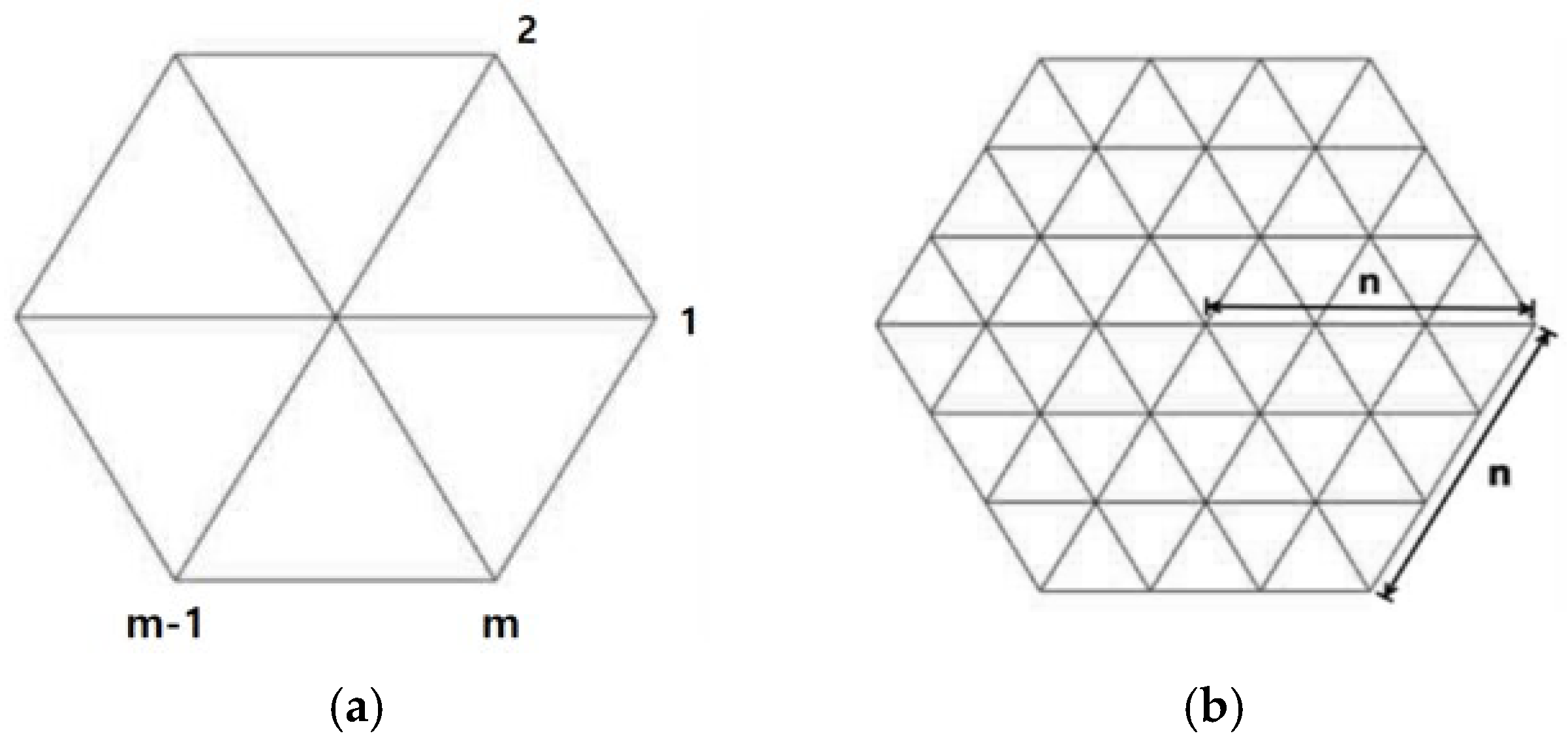
High antenna gain of a satellite requires high accuracy of the mesh reflector surface. The gain of a mesh reflector antenna is greatly affected by the parabolic shape of the reflector. The mesh reflector surface is composed of multiple equally sized triangular faces connected by a tensioned net [20]. The parabolic shape of the mesh reflector is maintained by the front/rear nets and the tension tie. As shown in Figure 2, the m-sided polygon of the mesh reflector is divided into m sectors, and each sector is subdivided into n x n triangles. The order n division of each m sector is called a subdivision.
The main parameters of the reflector were determined to satisfy the requirements: diameter (D) = 1.5 m, focal length (F) = 0.6~1.5 m, focal length to diameter ratio (F/D ratio) = 0.4~1.0, operation at frequency 1 GHz. The surface RMS error ( δ r m s ) of the reflector arises from various causes, including assembly alignment errors and thermal deformation of the structure. At this stage, the effect of approximating the required paraboloid surface with a polyhedral surface must be considered. Therefore, the surface RMS error was conservatively selected to less than approximately 1/100 of the wavelength. Since the wavelength at 1 GHz is 300 mm, the allowable surface RMS error was selected to 3 mm.
As the F/D ratio decreases, the curvature of the reflector deepens, so the number of subdivision (n) should increase to achieve the ideal curvature. Therefore, the number of subdivision was calculated based on diameter = 1.5 m, focal length = 0.6 m, and F/D ratio = 0.4. The selected main parameters and allowable surface RMS error were substituted into Equations (1) and (2) [21,22]. Considering Equations (1) and (2), the net subdivision n was determined to be 3.
n = s i n 1 ( 1 4 D F ) 2 s i n 1 ( 15 4 ( δ r m s D ( D F ) )
n = D 2 F δ r m s 15 ( 64 F 2 + D 2 )
where n, D, F and δ r m s mean net subdivision, diameter, focal length and allowable RMS error.

2.2. Design of Deployable Mesh Reflector Antenna

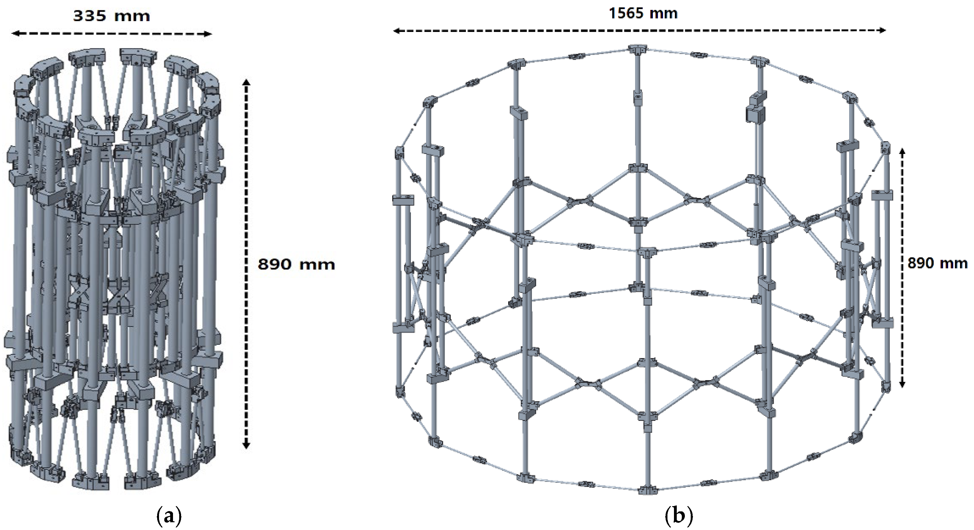
The deployable mesh reflector antenna consists of front/rear nets, mesh reflectors, tension ties, and ring trusses. The net and tension ties maintain the parabolic shape of the mesh reflector. The net and tension ties should have an appropriate tensile allowable load to maintain the parabolic shape and should be flexible for easy storage/deployment. In addition, the net and tension ties should have heat resistance to withstand extreme temperatures in the space orbit environment and should also have low permittivity to avoid electrical performance degradation of the mesh reflector. The mesh reflector is made of molybdenum or tungsten for high electrical conductivity, and is manufactured with a density and weave pattern that has high antenna gain in the L band, which is the antenna’s target operating frequency. The ring truss has high strength and rigidity and is manufactured with CFRP for low weight. In addition, a deployment synchronization module is added for deployment stability, and a stable storage/deployment mechanism design is required. The design requirements of the 1.5 m-scale deployable mesh antenna in this study are shown in Table 1. The total weight of the mesh antenna assembly must be less than 12 kg. The antenna diameter is 1.5 m or more when deployed and 0.5 m or less when stored, with a storage efficiency of 1 m or less. In addition, the design was performed to satisfy the fundamental frequency of the antenna to be 1 Hz or more when deployed and 33 Hz or more when stowed. Figure 3 is a design of deployable mesh reflector antenna considering design requirements.

3. Development of Deployable Mesh Reflector Antenna

3.1. Analysis of Deployable Mesh Reflector Antenna

3.1.1. Modal Analysis of Deployable Mesh Reflector Antenna

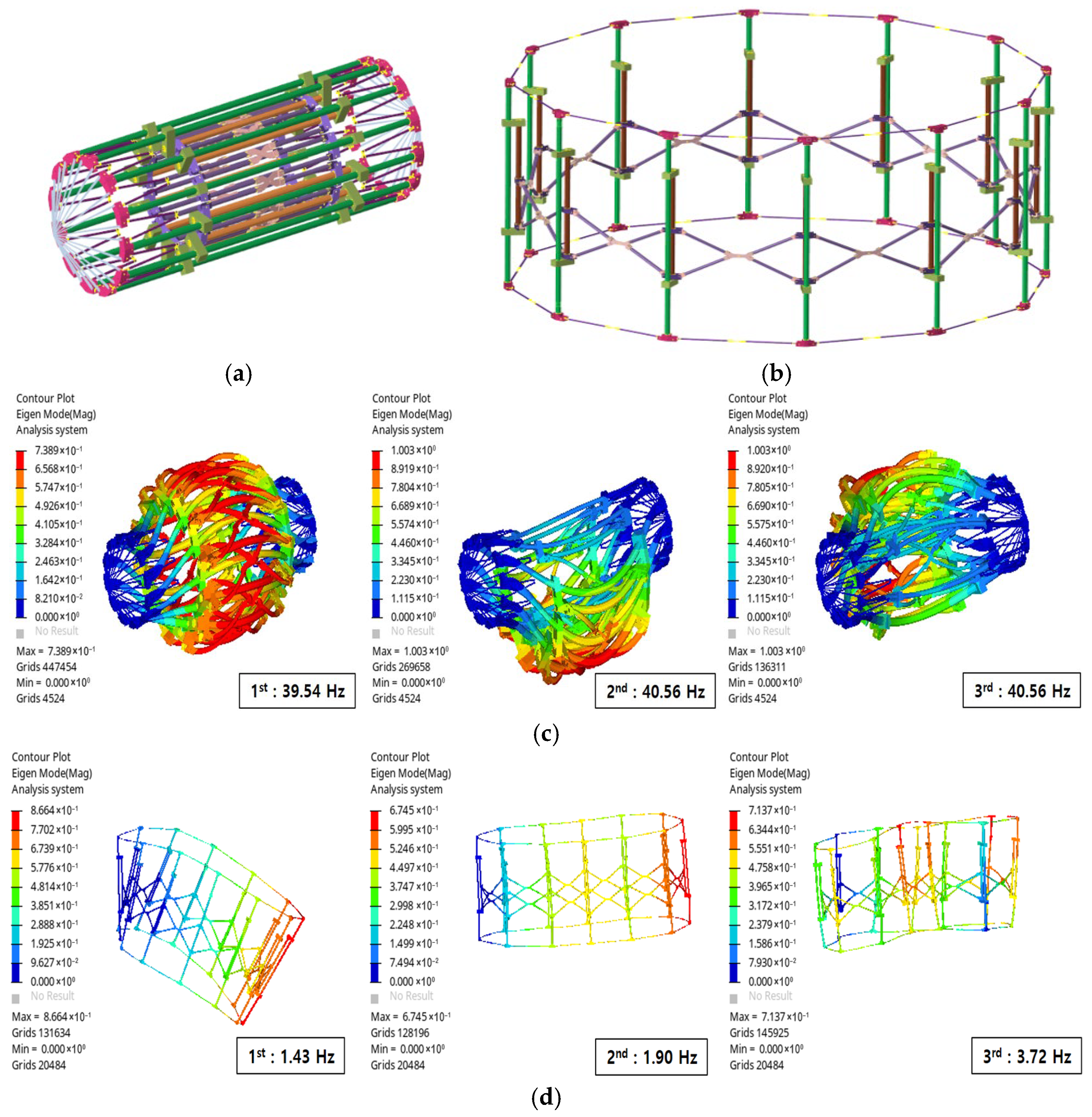
The fundamental frequency and vibration mode of an antenna are important antenna design factors [23,24]. Sufficient dynamic stiffness is required to prevent excitation caused by satellite attitude control during satellite orbital missions. Therefore, modal analysis was performed using Hypermesh software version 2023 to verify the fundamental frequency requirements for a 1.5 m-scale mesh antenna. The mesh antenna was connected to the satellite body by fixing one vertical truss to a boom, applying boundary conditions. The ring truss, the main structure, is made of CFRP, while the brackets and joints are both made of AL6061-T6. Figure 4 shows the fundamental frequency analysis results for the mesh antenna in the stowed and deployed conditions. The modal analysis results confirmed that the fundamental frequency of the mesh antenna in the stowed and deployed conditions satisfies the design requirements.

3.1.2. Load Analysis of Deployable Mesh Reflector Antenna

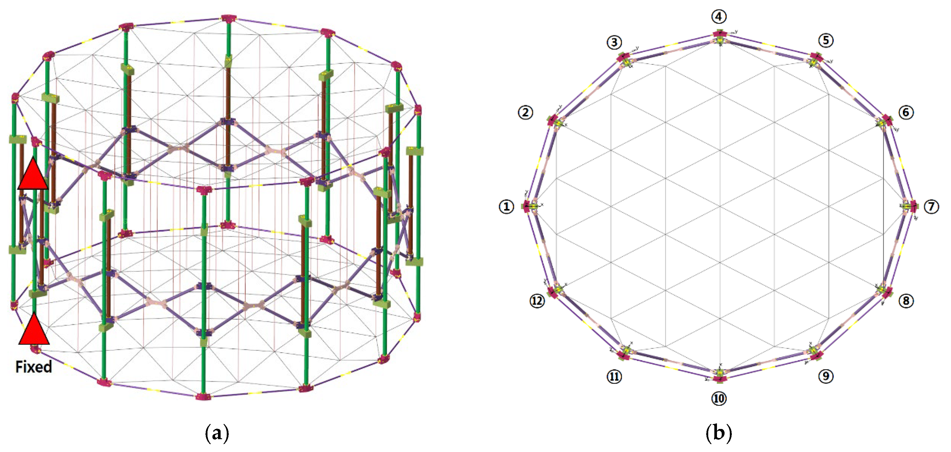
A structural analysis was performed to analyze the loads acting on a deployable mesh reflector antenna. The mesh and front net were assembled to the upper interface of the ring truss, while the rear net was assembled to the lower interface. The points where these nets intersect are referred to as nodal points, and the nodal points of the front and rear nets were connected by tension ties. The load applied to the interface of the ring truss depends on the tension applied to the tension ties. In this study, the 1.5 m-scale antenna has a total of 31 nodal points. If the tension ties are subjected to high tension, the high load applied to the interface of the ring truss could lead to misalignment. Therefore, the tension ties at each nodal point require an integrated assembly that ensures a maximum tension of 1 N. In this study, the load applied to the interface of the ring truss was analyzed under a 1 N tension applied to each nodal point. As shown in Figure 5, the loads acting on each interface were calculated under the condition of restraining the top and bottom of the CFRP vertical bar of the ring truss. Numbers 1–12 are interface nodes of the ring truss to which the net/mesh is connected. The results of the load analysis acting on each interface of the ring truss were shown in Table 2. The load was transmitted without significant deviation, with a maximum load of 15.6 N and a minimum load of 13.3 N. The ring truss possessed sufficient stiffness/strength, so there was no risk of misalignment of the assembly, even under the load acting on the interface.

3.2. Assembly of Deployable Mesh Reflector Antenna

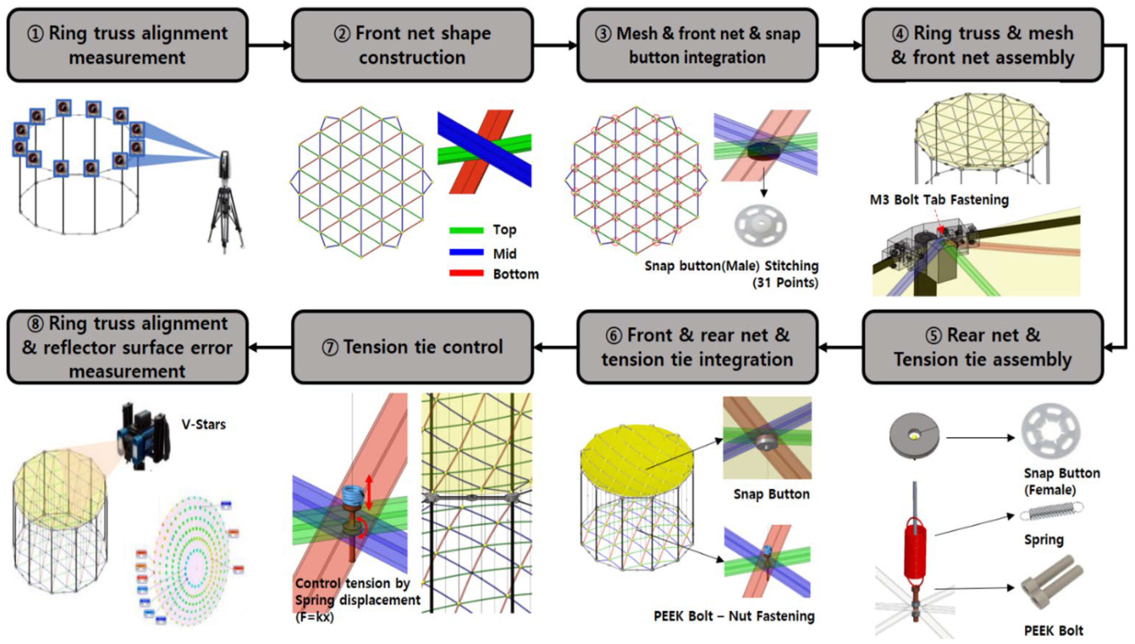
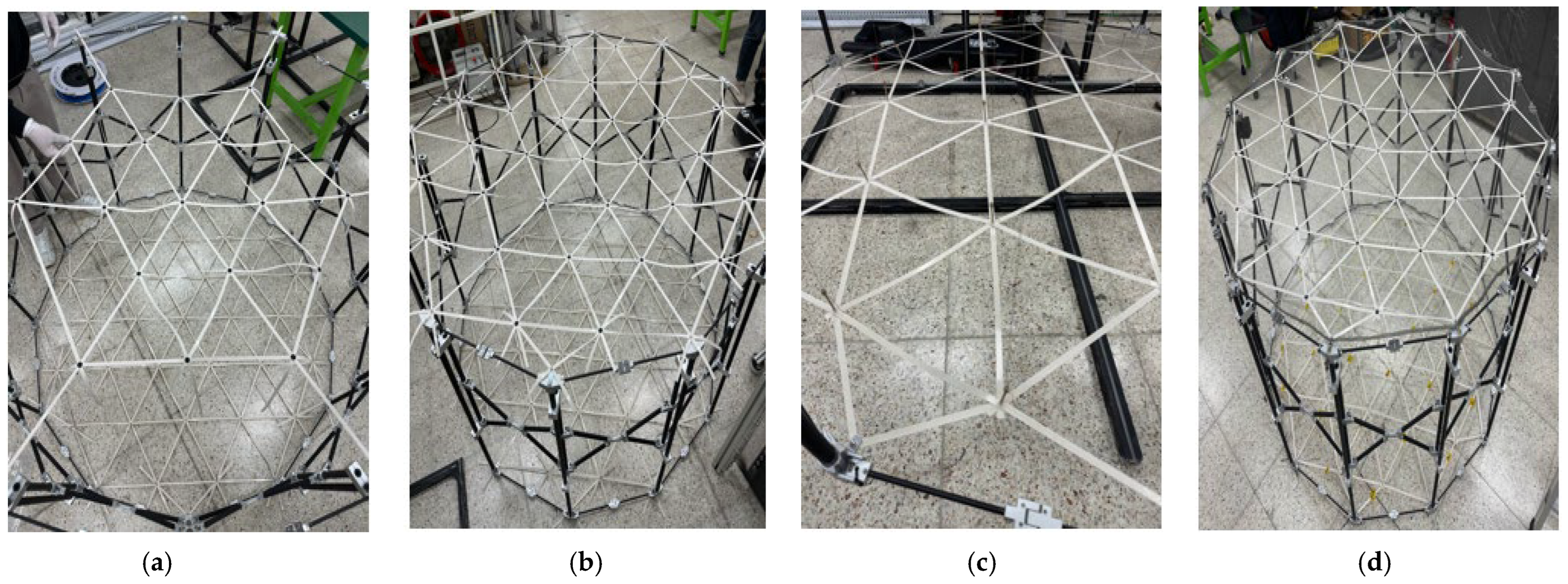
For the assembly/integration of the deployable mesh reflector antenna, front/rear nets, mesh reflectors, tension ties, and ring trusses were fabricated. The nets were fabricated using Teflon-coated E-glass fabric. The mesh reflectors were fabricated using molybdenum material, with an Atlas–Atlas weaving pattern. The ring truss was a circular strut shape made of CFRP, and a deployment synchronization module was additionally designed and fabricated for deployment stability. The mesh antenna was assembled using the procedure shown in Figure 6. The alignment of the ring truss was measured using a laser tracker. Next, the front net shape was constructed, and the mesh reflectors and front net were integrated using snap buttons. The rear net shape was constructed using peak bolts and springs, and the female snap buttons and springs were connected with tension ties. Next, the front net, rear net, and tension ties were integrated by assembling male and female snap buttons. After that, the height of the peak bolts was adjusted to satisfy the surface RMS error of the mesh reflector, and the tension of the tension ties was adjusted. The tension of the tension ties was adjusted so that it did not exceed 1 N while checking the spring length. After adjusting the tension tie, the surface RMS error of the mesh reflector was measured using the V-STARS equipment. The tension adjustment of the tension tie was repeated until the surface RMS error requirement of less than 3 mm of the mesh reflector was satisfied. Table 3 shows the weights of each component, and Figure 7 shows the assembly process of the mesh reflector antenna.

4. Experiment of Deployable Mesh Reflector Antenna

4.1. Deployment Test of Mesh Reflector Antenna

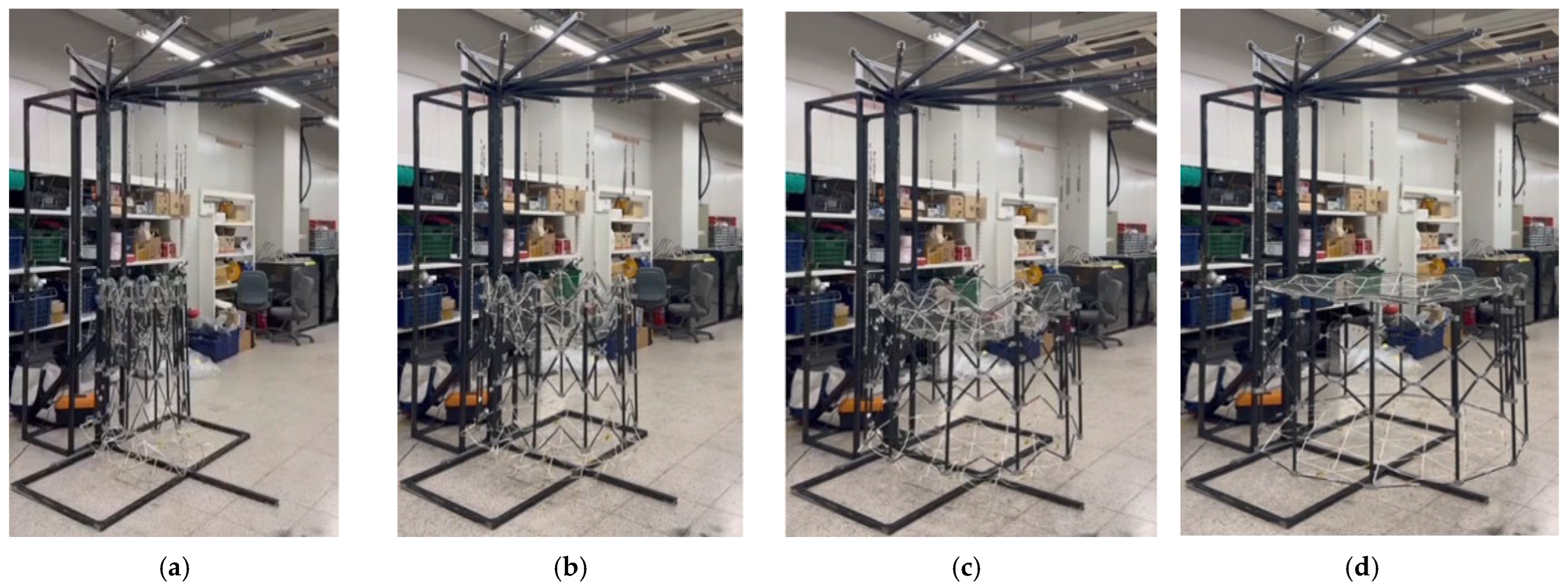
The integrated assembly of the mesh reflector antenna was previously performed. Next, the antenna’s storage/deployment function was tested. A gravity compensation device was used for the antenna deployment function test. The gravity compensation device was fabricated from aluminum profiles, and its upper portion was assembled in a fan shape in the direction of the ring truss deployment. The gravity compensation device was connected to the I-bolt of the antenna deployment device interface, using a cable. The gravity compensation device includes a function to adjust the cable length using a computer bolt, allowing the height of each interface of the antenna deployment device to be adjusted. The antenna was deployed from a stored state using the antenna deployment device’s motor. Figure 8 shows the deployment test of the reflector antenna, which took approximately 70 s to fully deploy. No problems, such as twisting or interference between antenna components, occurred during the antenna deployment. The antenna continued to perform the deployment function without any problems in three additional repeated deployment tests.

4.2. Thermal Vacuum Test of Deployable Mesh Reflector Antenna

This section discusses the thermal vacuum test results of the deployable mesh reflector antenna. The thermal vacuum test was performed in a thermal vacuum chamber (TVC36) with an effective diameter of 3.6 m and an effective depth of 5 m, at the Korea Aerospace Research Institute (KARI). Figure 9 shows the thermal vacuum test setup and test results of the deployable mesh reflector antenna. The thermal vacuum test was conducted with the antenna deployed. The thermal vacuum test specifications are as shown in Table 4. The temperature reference point (TRP) is the AL bracket, which is the interface of the ring truss, where the front net and mesh are connected. The temperature condition of the TRP was selected as ±60 °C, considering the uncertainty and margin in the results from the orbit analysis using the thermal desktop tool. The test cycle was a total of eight cycles, including the initial high temperature and low temperature thermal balance, and the thermal balance criterion was selected as being within 1 °C for 4 h. In the cycle test after the thermal balance, the dwell time was maintained for 1 h each, and the air pressure was maintained below 5   ×   10 5  torr. A total of 94 thermocouples (TC) were attached: 24 TC to the antenna deployment device CFRP truss, 24 TC to the AL bracket, 4 TC to the mesh, 6 TC to the net, and 6 TC to the tension tie and MGSE, etc. The thermal vacuum test took approximately 5 days to complete eight cycles. Following the thermal vacuum test, a deployment test using a gravity compensation device was performed, and the antenna deployment function was found to be functioning without any problems.

4.3. Reflector Surface RMS Error Measurement of Mesh Reflector Antenna

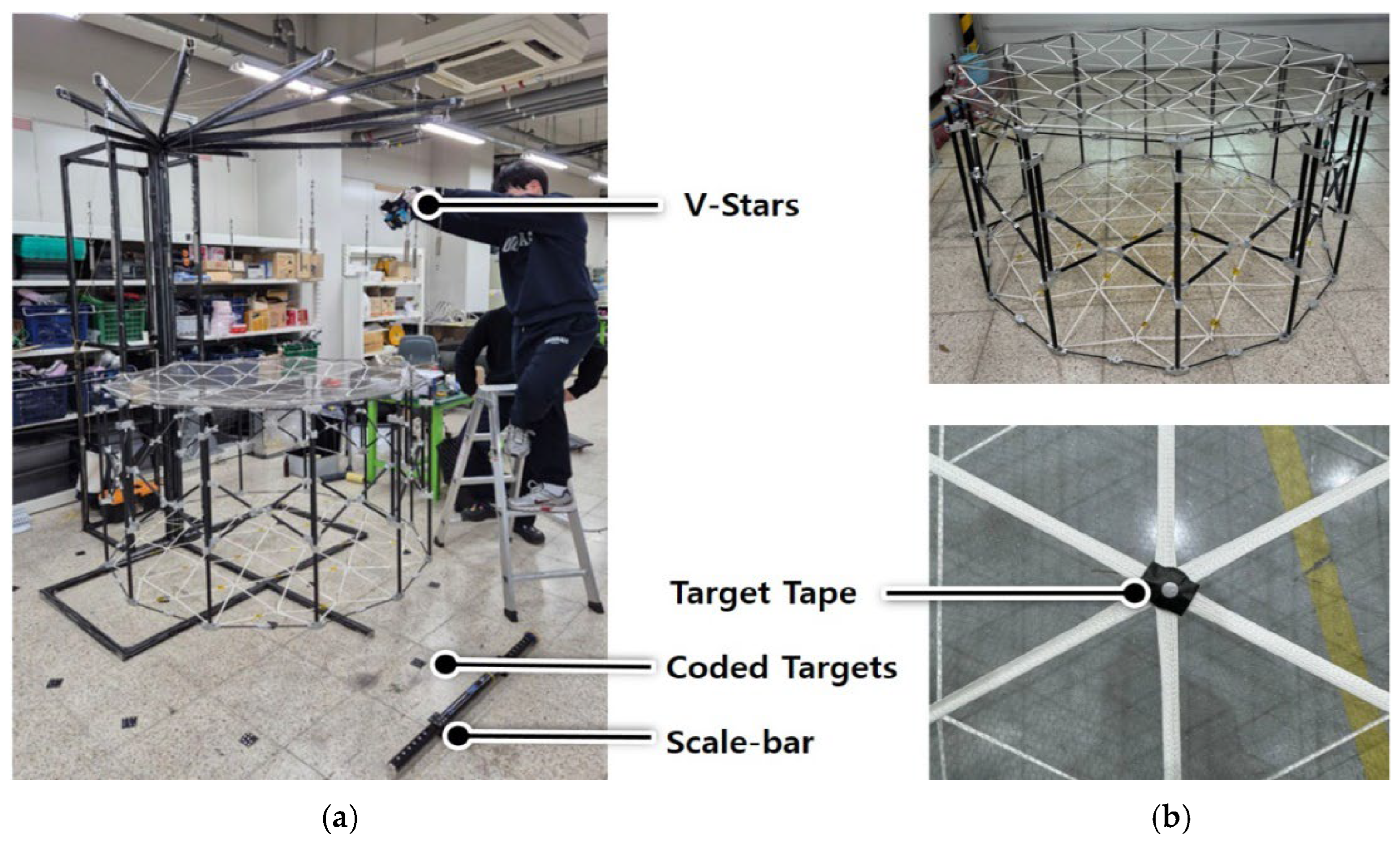
Using a high-accuracy portable 3D measuring device called V-Stars, the surface RMS error of the reflector was measured. As shown in Figure 10, the V-Stars’ target tape was applied to all nodal points of the mesh antenna, and a scale-bar and multiple coded targets were placed around the antenna. The mesh antenna was suspended from a gravity compensation device. Figure 11 shows the results of measuring the surface RMS error of the reflector surface at each stage.
The surface RMS error of a mesh reflector antenna directly affects its RF performance. To maximize antenna RF performance, we optimized the reflector surface design. Using antenna performance analysis, we measured the surface RMS error of the antenna, based on the optimized antenna surface. Therefore, the lower the antenna RMS error, the more effective the antenna’s RF performance. The mesh reflector antenna had a total of 31 nodal points, and during the initial assembly, the RMS of each nodal point was measured to be high. Bolts were installed at each nodal point to finely adjust the tension tie tension. By adjusting the bolt length, the tension tie was controlled, resulting in an RMS error of 2.8 mm: well within the initial design RMS of 3 mm. The RMS of the reflector surface remained at 2.8 mm, even after repeated antenna deployment tests. Finally, the RMS of the reflective surface after the thermal vacuum test increased slightly to 3 mm compared to the original, but satisfied the initial design requirements of 3 mm RMS.

5. Conclusions

In this paper, the development process of a 1.5 m-scale deployable mesh reflector antenna was described. This is the first mesh reflector antenna developed in South Korea, and the results of this study will be used to gradually expand the antenna size. In the initial design of the antenna, the antenna operating frequency was determined to be 1 GHz, and the allowable surface RMS error of the reflector was determined to be within 3 mm. The number of subdivisions in the reflector was then determined to be three, based on the literature, and the initial design of the antenna reflector surface was performed. For the development of the 1.5 m-scale deployable mesh reflector antenna, the design requirements included antenna weight, stowed/deployed diameter, antenna height, and the fundamental frequency during stowed/deployed condition. The ring truss was made of CFRP, and all hinge brackets were made of AL6061-T6. The mesh was made of molybdenum, the net was made of GFRP, and the tension ties were made of yarn-shaped E-glass. Before fabricating each component, modal analysis was performed to confirm that the fundamental frequency requirements were satisfied during the antenna’s stowed/deployed condition. Additionally, load analysis was performed at the interface where the ring truss, net, and mesh were assembled. When the 1 N of tension was applied to all nodal points, the ring truss experienced a maximum load of approximately 15 N. The ring truss possessed sufficient strength and rigidity, resulting in only minimal deformation. Each antenna component was fabricated, and the mesh antenna was integrated, according to the assembly procedure. The V-Stars equipment was used to measure the surface RMS errors of the reflector and adjust the tension tie tension at each nodal point. Repeated deployment and thermal vacuum tests were then performed to verify the mechanical and thermal stability of the antenna. Finally, the development verification of the 1.5 m-scale antenna was completed by satisfying the design requirement of 3 mm in the reflective surface’s RMS error, before and after the repeated deployment and thermal vacuum test.

Author Contributions

Conceptualization, C.L.; methodology, C.L. and S.K.; software, C.L.; validation, R.D. and Y.L.; formal analysis, C.L. and D.K.; investigation, G.B. and I.J.; resources, K.K.; data curation, C.L.; writing—original draft preparation, C.L. All authors have read and agreed to the published version of the manuscript.

Funding

This work was supported by the Korea Research Institute for Defense Technology Planning and Advancement (KRIT), with a grant funded by the Defense Acquisition Program Administration (DAPA) (21-307-A00-013, Korean BFT Communication Satellite Large Antenna Technology).

Institutional Review Board Statement

Not applicable.

Informed Consent Statement

Not applicable.

Data Availability Statement

The original contributions presented in the study are included in the article, further inquiries can be directed to the corresponding author.

Conflicts of Interest

Authors ChulHyung Lee, DongGeon Kim, RyoonHo Do, SeungHyun Kim, GyeongHun Bae and KyungRae Koo were employed by the company Hanwha Systems. Authors YoonPyo Lee and InO Jung were employed by the company Korean Air.

References

  1. Ince, F. Nano and Micro satellites as the Pillar of the “new space” Paradigm. J. Aeronaut. Space Technol. 2020, 13, 235–250. [Google Scholar]
  2. Logue, T.J.; Pelton, J. Overview of Commercial Small Satellite systems in the “New Space” Age. In Handbook of Small Satellites; Springer Nature: Cham, Switzerland, 2019; pp. 69–86. [Google Scholar]
  3. Gao, S.; Clark, K.; Unwin, M.; Zackrisson, J.; Shiroma, W.; Akagi, J.; Maynard, K.; Garner, P.; Boccia, L.; Amendola, G. Antennas for Modern Small Satellites. IEEE Antennas Propag. Mag. 2009, 51, 40–56. [Google Scholar] [CrossRef]
  4. Rahmat-Samii, Y.; Densmore, A.C. Technology Trends and Challenges of Antennas for Satellite Communication Systems. IEEE Trans. Antennas Propag. 2014, 63, 1191–1204. [Google Scholar] [CrossRef]
  5. Bayer, H.; Krauss, A.; Zaiczek, T.; Stephan, R.; Enge-Rosenblatt, O.; Hein, M.A. Ka-Band User Terminal Antennas for Satellite Communications [Antenna Applications Corner]. IEEE Antennas Propag. Mag. 2016, 58, 76–88. [Google Scholar] [CrossRef]
  6. Miura, K.; Miyazaki, Y. Concept of the Tension Truss Antenna. AIAA J. 1990, 28, 1098–1104. [Google Scholar] [CrossRef]
  7. Thomson, M.W. The AstroMesh deployable reflector. IEEE Antenna Propag. Soc. Int. Symp. 1999, 3, 1516–1519. [Google Scholar]
  8. Thomson, M.W. AstroMesh Deployable Reflector for Ku and Ka Band Commercial Satellites. In Proceedings of the 20th AIAA International Communication Satellite Systems Conference Exhibit, Montreal, QC, Canada, 12–15 May 2002; p. 2032. [Google Scholar]
  9. Yang, G.; Zhang, Y.; Tang, A.; Li, Y. A design approach for AstroMesh-type contoured-beam reflector antennas. IEEE Antennas Wirel. Propag. Lett. 2018, 17, 951–955. [Google Scholar] [CrossRef]
  10. Zhang, Y.; Ru, W.; Yang, G.; Li, N. Deployment analysis considering the cable-net tension effect for deployable antennas. Aerosp. Sci. Technol. 2016, 48, 193–202. [Google Scholar] [CrossRef]
  11. Liu, W.; Li, D.; Jiang, J. General Mesh Configuration Design Approach for Large Cable-Network Antenna Reflectors. J. Struct. Eng. 2013, 140, 04013051. [Google Scholar]
  12. Fu, K.; Du, J.; Li, J.; Zhao, Z. Robust Design of Tension Truss Antennas Against Variation in Tension Forces. AIAA J. 2018, 56, 3374–3381. [Google Scholar] [CrossRef]
  13. Gao, C.; Wang, H.; Yang, N.; Guo, J.; Liu, F.; Du, J. A Large-Span Ring Deployable Perimeter Truss for the Mesh Reflector Deployable Antenna. Symmetry 2025, 17, 1388. [Google Scholar] [CrossRef]
  14. Gao, C.; Kang, X.; Lei, H.; Xu, P.; Li, B. Design and analysis of a novel large-span two-fold deployable mechanism. Mech. Mach. Theory 2023, 186, 105352. [Google Scholar] [CrossRef]
  15. Du, X.; Du, J.; Bao, H.; Chen, X.; Wu, X. Dynamic analysis of the deployment for mesh reflector antennas driven with variable length cables. J. Comput. Nonlinear Dyn. 2019, 14, 111006. [Google Scholar] [CrossRef]
  16. Han, B.; Zhou, Y.; Zhao, Y. Kinematics and dynamics characteristics analysis of a double-ring truss deployable mechanism based on rectangular scissors unit. Eng. Struct. 2024, 307, 117900. [Google Scholar] [CrossRef]
  17. Han, B.; Xu, Y.; Yao, J.; Zheng, D.; Guo, L.; Zhao, Y. Type synthesis of deployable mechanism for ring truss antenna based on constraint-synthesis method. Chin. J. Aeronaut. 2020, 33, 2445–2460. [Google Scholar] [CrossRef]
  18. Li, B.; Qi, X.; Huang, H.; Xu, W. Modeling and analysis of deployment dynamics for a novel ring mechanism. Acta Astronaut. 2016, 120, 59–74. [Google Scholar] [CrossRef]
  19. Cao, W.; Xi, S.; Ding, H.; Chen, Z. Design and kinematics of a novel double-ring truss deployable antenna mechanism. J. Mech. Des. 2021, 143, 124502. [Google Scholar] [CrossRef]
  20. Shi, H.; Yuan, S.; Yang, B. New Methodology of Surface Mesh Geometry Design for Deployable Mesh Reflectors. J. Spacecr. Rocket. 2018, 55, 266–281. [Google Scholar] [CrossRef]
  21. Liu, R.; Guo, H.; Liu, R.; Tang, D.; Wang, H.; Deng, Z. Design and form finding of cable net for a large cable-rib tension antenna with flexible deployable structures. Eng. Struct. 2019, 199, 109662. [Google Scholar] [CrossRef]
  22. Yuan, S.; Yang, B.; Fang, H. The Projecting Surface Method for improvement of surface accuracy of large deployable mesh reflectors. Acta Astronaut. 2018, 151, 678–690. [Google Scholar] [CrossRef]
  23. Fanning, P.; Hollaway, L. The deployment analysis of large space antenna. Int. J. Space Struct. 1993, 8, 209–220. [Google Scholar] [CrossRef]
  24. Peng, Y.; Zhao, Z.; Zhou, M.; He, J. Flexible Multibody Model and the Dynamics of the Deployment of Mesh Antennas. J. Guid. Control. Dyn. 2017, 40, 1499–1506. [Google Scholar] [CrossRef]
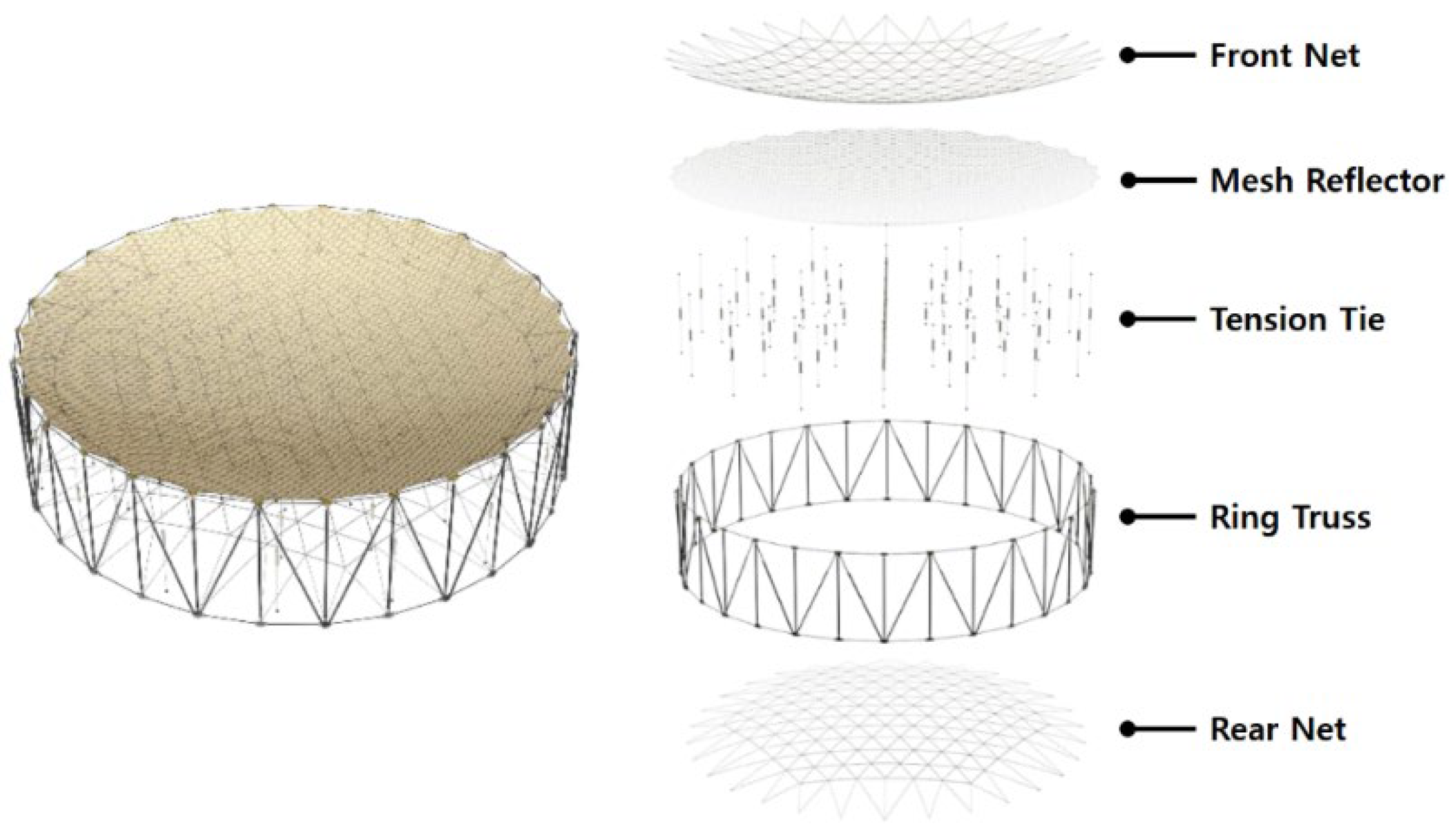
Figure 1. Concept of deployable mesh reflector antenna.
Applsci 15 11529 g001
Figure 2. Initial design of mesh reflector antenna net: (a) m side polygon; (b) subdivision of order n.
Applsci 15 11529 g002
Figure 3. Design of deployable mesh reflector antenna under (a) stowed condition; (b) deployed condition.
Applsci 15 11529 g003
Figure 4. Mode analysis of the deployable mesh antenna under the stowed and deployed conditions; (a) stowed and (b) deployed conditions; mode frequencies and shapes of (c) 1st, 2nd, and 3rd mode with the stowed condition and (d) 1st, 2nd, and 3rd mode with the deployed condition.
Applsci 15 11529 g004
Figure 5. Load analysis model of the deployable mesh antenna (a) constraint of analysis model; (b) node number.
Applsci 15 11529 g005
Figure 6. Assembly process of deployable mesh reflector antenna.
Applsci 15 11529 g006
Figure 7. Assembly of deployable mesh reflector antenna: (a) net shape construction; (b) net and tension tie integration; (c) tension tie control; and (d) mesh antenna assembly.
Applsci 15 11529 g007
Figure 8. Deployment test of the mesh reflector antenna: (a) t = 0 s; (b) t = 10 s; (c) t = 30 s; (d) t = 70 s.
Applsci 15 11529 g008
Figure 9. Thermal vacuum test results of deployable mesh reflector antenna: (a) the test configuration of the thermal vacuum test; (b) the time history of temperature and pressure.
Applsci 15 11529 g009
Figure 10. Surface RMS error measurement of mesh reflector using V-Stars: (a) the measurement configuration of the Surface RMS error; (b) V-Stars target tape on the nodal point.
Applsci 15 11529 g010
Figure 11. Surface RMS error results of the mesh reflector, using the V-Stars: (a) before and (b) after tension tie control; (c) after deployment test; (d) after thermal vacuum test.
Applsci 15 11529 g011
Table 1. Design requirements of the deployable mesh reflector antenna.
RequirementValue
MassAntenna assembly≤12 kg
Antenna diameterDeployed condition≥1.5 m
Stowed condition≤0.5 m
Antenna heightDeployed and stowed condition≤1.0 m
Fundamental frequencyDeployed condition≥1 Hz
Stowed condition≥33 Hz
Table 2. Load analysis results of ring truss interface.
Node No.Reaction X (N)Reaction Y (N)Reaction Z (N)Total Load (N)
115.30−0.09−2.9215.57
214.532.50−2.5414.96
313.280.69−2.8813.61
413.05−0.56−2.5313.30
513.18−1.75−2.8813.61
614.34−3.42−2.5414.96
715.29−0.56−2.9215.58
814.532.43−2.5314.95
913.240.99−2.8813.59
1013.090.00−2.5313.34
1113.24−1.07−2.8813.60
1214.48−2.74−2.5414.96
Table 3. Components weight of deployable mesh reflector antenna.
ContentsNumberWeight
Front net1 Set0.1 kg
Mesh reflector1 Set0.2 kg
Tension tie31 Sets0.4 kg
Rear net1 Set0.1 kg
Ring truss1 Set10.6 kg
Total assembly11.4 kg
Table 4. Thermal vacuum test specifications.
Test ClassificationSpecification
TRP temperature±60 °C
Test cycles8 Cycles
Test temperature tolerance(Hot) 0/+4 °C
(Cold) −4/0 °C
Temperature transition rate3 °C/min
Thermal balance criteria1 °C/4 h
Thermal dwell time1 h
Thermal vacuum pressure 5   ×   10 5  torr
Disclaimer/Publisher’s Note: The statements, opinions and data contained in all publications are solely those of the individual author(s) and contributor(s) and not of MDPI and/or the editor(s). MDPI and/or the editor(s) disclaim responsibility for any injury to people or property resulting from any ideas, methods, instructions or products referred to in the content.