Abstract
As an innovative approach to advancing sustainable construction, this study explores the integration of molybdenum tailings as fine aggregate in 3D-printed mortar. The rheological and mechanical properties of the developed mixtures are systematically investigated. Environmental and economic assessments demonstrate that molybdenum tailings sand exhibits negligible global warming potential (GWP), acidification potential (AP), and cumulative energy demand (CED), completely avoiding the environmental impacts associated with natural sand extraction. Economically, full replacement with molybdenum tailings reduces material costs, as the tailings are typically provided without charge by mining enterprises. Furthermore, the template-free 3D printing technology eliminates formwork-related environmental impacts and simplifies construction processes. Experimental results indicate that mortars with cement-to-sand ratios between 1:1 and 1:2 possess favorable printability, with nozzle movement parameters significantly influencing printed dimensions. While increased molybdenum tailings content reduces mechanical strength, the cement-to-sand ratio exerts a more pronounced effect. The compressive strength of mold-printed and free-printed mortar reaches 55–75% and 35–55% of conventional mortar, respectively. Anisotropy analysis reveals minimal directional dependence in flexural strength, whereas compressive strength shows clear anisotropy, with X-direction strength measuring approximately 70% of that in the Y direction. This research provides valuable insights into the sustainable design and performance optimization of 3D-printed mortar using industrial byproducts.
1. Introduction
In recent years, 3D printing concrete technology has gained significant attention in the construction industry due to its advantages, including formwork elimination, high automation, cost-effectiveness, and environmental friendliness [1,2]. This study focuses on the application of molybdenum tailings in 3D-printed mortar, mainly investigating the systematic effects of molybdenum tailings as a fine aggregate replacement on the rheological properties, mechanical performance, and anisotropy of 3D-printed mortar, and establishing an optimized mix design method suitable for construction 3D printing. As an additive manufacturing technology, 3D printing enables the realization of digital models through layer-by-layer deposition, and its convenience has driven its rapid development across multiple industries, accelerating the rise of 3D-printed concrete [3].
With the ongoing acceleration of global urbanization, the demand for concrete continues to increase [4]. Although concrete meets the needs of societal development, its large-scale application has also led to serious environmental problems [5]. Concrete is typically composed of cement, aggregates (including fine aggregates such as natural river sand and manufactured sand, as well as coarse aggregates like gravel), water, and additives or mineral admixture [6]. Among them, natural river sand, a non-renewable resource, is being depleted due to excessive mining, causing ecological degradation [7,8,9]. Therefore, it is urgent to seek a sustainable transformation of traditional concrete materials.
In response, many scholars have conducted numerous experimental studies and literature reviews, exploring multiple aspects ranging from material substitution and structural optimization to life-cycle impact assessment [10]. These investigations focus on the feasibility of replacing conventional materials with solid waste and their application pathways toward sustainable development in the construction industry. The primary objectives are to reduce resource consumption and carbon emissions, and mitigate environmental and economic burdens, while ensuring or enhancing the mechanical properties and durability of concrete.
Among various alternative materials, molybdenum tailings have recently attracted attention for their potential environmental and functional benefits in construction applications. Recent studies have demonstrated that molybdenum tailings exhibit good compatibility across various cement-based material systems [11,12,13], thereby laying a solid foundation for their application in emerging construction technologies. However, their application in 3D-printed concrete remains largely underexplored, presenting a valuable opportunity for innovation in sustainable construction.
To better understand their potential in concrete applications, it is important to first examine the origin and environmental impact of molybdenum tailings. Molybdenum tailings are a type of solid waste produced during the extraction of molybdenum. As shown in Figure 1, global molybdenum production has surged from 80,000 metric tons in 1985 to 320,000 metric tons by 2020, with China dominating output (contributing 20%, 14%, and 13% from Henan, Shaanxi, and Jilin provinces, respectively. Due to limitations in current extraction technology, only approximately 5% of the molybdenum present in the raw ore can be effectively recovered, leading to significant accumulation of molybdenum tailings [14].

Figure 1.
Production trends, major mining regions, and ore morphology of molybdenum resources in China.
The long-term storage of molybdenum tailings not only occupies substantial land resources but also poses potential environmental risks. Although the primary components of molybdenum tailings consist of silicate and oxide mineral phases, they may contain leachable heavy metal elements (e.g., molybdenum, copper, or lead) that can migrate into soil and water systems through rainwater leaching during extended storage, consequently posing ecological risks [15,16]. Furthermore, additional environmental concerns include dust pollution from tailings particles and geotechnical hazards associated with tailings impoundment areas. Therefore, some researchers have explored their use to replace cement, aggregates, quartz sand, and silica fume to reduce both environmental and economic burdens.
Compared with other types of tailings such as iron tailings, copper tailings, and gold tailings, the production volume and storage issues of molybdenum tailings are particularly prominent in China, with concentrated mining areas and large accumulated stockpiles, while the current resource utilization rate is extremely low. In addition, molybdenum tailings have relatively smaller particle sizes, which may lead to performance reduction, but at reasonable replacement ratios, they can provide a certain micro-filling effect and partially react pozzolanically with cement hydration products, improving the density of the mortar. Meanwhile, molybdenum tailings contain low-corrosive components and exhibit specific heavy metal leaching characteristics [17]. More importantly, research on molybdenum tailings has mainly focused on ordinary concrete, whereas systematic studies in the field of 3D-printed concrete remain lacking, providing an innovative opportunity for its high-value utilization.
Therefore, this study selects molybdenum tailings rather than other tailings materials, aiming to explore its feasibility in 3D-printed mortar and to provide a reference path for regional solid waste utilization and sustainable construction development.
Gao et al. [16] investigated the utilization of molybdenum tailings (MoT) as a replacement for natural fine aggregate in structural concrete. The study comprehensively evaluated the properties of the resultant concrete, the behavior of reinforced concrete (RC) and concrete-filled steel tubular (CFST) columns incorporating it, and the associated environmental impact. The results demonstrated that the molybdenum tailings, with radionuclide concentrations complying with standard limits, are suitable for preparing structural concrete at an appropriate replacement ratio. It was found that increasing the MoT replacement ratio leads to a reduction in the workability, mechanical properties, and durability performance of the concrete.
Similarly, Gao et al. [18] investigated the utilization of recycled lump prepared from waste concrete after elevated temperatures, highlighting its potential to reduce environmental impact and global warming from concrete production, which aligns with the sustainable goals of using alternative materials like molybdenum tailings.
Quan et al. [19] replaced natural river sand with molybdenum tailings (MTS) as fine aggregate to prepare molybdenum tailings concrete (MTS-C). The mechanical properties, corrosion resistance and pore microstructure characteristics of the specimens were analyzed using methods such as mechanical performance testing, nuclear magnetic resonance (NMR), and industrial CT scanning. The results indicated that when the molybdenum tailings substitution rate was 60%, the compressive strength and splitting tensile strength of the concrete decreased by less than 10% exhibiting favorable mechanical properties. Under sulfate freeze–thaw cycles, the corrosion resistance of MTS-C decreased as the substitution rate increased, with a significant decline observed when the substitution rate exceeded 60%. The porosity decreased in the early stages of the freeze–thaw cycle due to the filling of corrosion products, but later increased due to pore expansion and connectivity. The gradual evolution of small pores into large pores was identified as the primary mechanism for the degradation of the pore structure of MTS-C under sulfate freeze–thaw cycles. Comprehensive performance evaluation suggested that a 60% molybdenum tailings substitution rate is feasible for concrete production.
Luo et al. [20] replaced part of the cementitious paste with molybdenum tailings (MT) at different substitution rates (0–10%) to prepare concrete and investigated the impact on its properties. The results indicated that with an increase in MT substitution rate, the slump of the concrete decreased and the air content first increased and then decreased. The mechanical properties initially declined and then improved, with a compressive strength of 45.6 MPa and a splitting tensile strength of 2.9 MPa at a 10% substitution rate. NMR analysis showed that a substitution rate of 7.5–10% reduced capillary pores (0–100 nm) and increased pore connectivity, SEM observations confirmed the formation of a dense microstructure at a 10% substitution rate. The study concludes that replacing 10% of the cementitious paste with MT optimizes the concrete’s performance.
Based on the aforementioned studies and field investigations, previous research has indicated that molybdenum tailings, as a sustainable aggregate, can help alleviate the shortage of natural river sand, cement, and silica fume. Building on this foundation, the present study aims to explore the potential application of molybdenum tailings in 3D-printed mortar, providing a scientific basis for the development of eco-friendly 3D-printed mortar, while offering reference pathways for regional solid waste utilization and sustainable construction development.
2. Experimental Materials and Methods
2.1. Experimental Materials and Instruments
2.1.1. Raw Materials
The materials used in this study consisted of P.II 52.5 ordinary Portland cement supplied by Xi’an Building Materials Science and Technology Group Co., Ltd. (Xi’an, Shaanxi Province, China); screened natural sand with particle size below 1.18 mm (bulk density: 1.551 g/cm3; fineness modulus: 3.19; moisture content: 1.79%); molybdenum tailings sand with particle size below 1.18 mm (bulk density: 1.461 g/cm3; fineness modulus: 1.81; moisture content: 0.22%); a water-reducing agent at 0.3% dosage by weight; and a thickening agent at 0.4% dosage by weight. To ensure material reliability, standard performance tests were conducted on the cement, including setting time and mortar strength measurements. Furthermore, particle size distribution analysis was performed on both the natural sand and molybdenum tailings to characterize their granular properties and provide essential data for the mix proportion design. The resulting particle size distribution curves are presented in Figure 2.
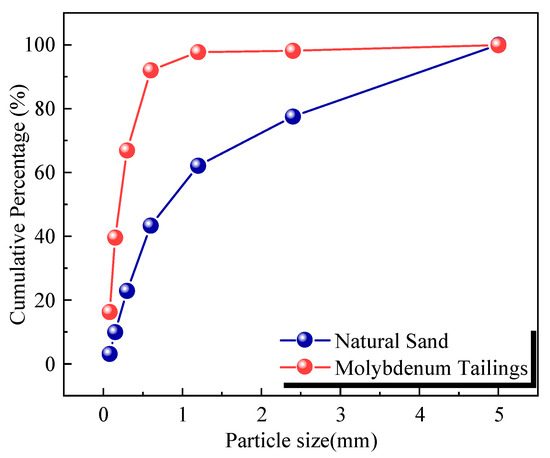
Figure 2.
Particle size distribution curve of natural sand-molybdenum tailings mixture.
2.1.2. Three-Dimensional Printing Equipment
The 3D printing equipment used in this study was the ZDJ-ZCM-Sun-II cement-based material 3D printer (as shown in Figure 3), capable of printing conventional building materials such as paste, mortar, and ultra-high-performance concrete, and supporting the controlled placement of continuous fibers. The device is equipped with built-in monitoring sensors and features a four-axis linkage, manual and automatic controls, and three-dimensional spatial interpolation functions, significantly enhancing work efficiency and reducing operator workload. The system stability of the equipment is high, with a pulse frequency of up to 400 kHz, and it is equipped with four feeding axes and one simulated main axis, offering a high-speed interpolation function of 2 ms, greatly improving processing speed, accuracy, and surface quality. The printing path, as shown in Figure 4, demonstrates the device’s movement pattern and trajectory planning during the printing process. However, Figure 4 primarily illustrates the trajectory planning of the printing path and does not fully depict the geometric shape or specific structural details of the printed specimens. In this study, the specimens were typically designed as rectangular prisms with dimensions of 40 mm × 40 mm × 160 mm. The materials used for specimen fabrication included cement, molybdenum tailings sand, natural sand, water-reducing agents, thickeners, and other additives. During the printing process, precise control measures were implemented to ensure adequate interlayer bonding strength and a smooth surface finish. The geometric design of the specimens was determined based on specific functional requirements, such as mechanical performance testing. To ensure the accuracy and reliability of the experimental data, rigorous evaluations—including dimensional accuracy checks and surface quality assessments—were conducted throughout the testing process. Through four-axis linkage and three-dimensional spatial interpolation, the equipment can precisely control the movement of the print head according to the predefined G-code instructions, ensuring the continuity and accuracy in the printing path. The printed path diagram clearly illustrates the movement trajectory of the device along the X, Y, and Z axes and the precise spatial positioning of the print head. This efficient path planning improves both printing performance and ensures the surface quality and structural stability of the printed product.

Figure 3.
ZDJ-ZCM-Sun-II cement-based material 3D printer.
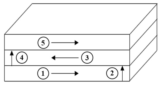
Figure 4.
Printing path diagram.
2.2. Mortar Mix Design
In this study, mortar mix proportions for different strength grades were designed based on the “Specification for Mix Proportion Design of Masonry Mortar” (JGJ/T98-2010) [21] and supporting research in the 3D printing literature. The design strength of the mortar can be calculated using Equation (1), in which the standard deviation of the mortar strength may be selected based on the construction quality as referenced in Table 1. The values presented in Table 1 are derived from the current Chinese standard for “Standard for test method of basic properties of construction mortar” (JGJ/T 70-2009) [22].
is the configured strength of the mortar; is the design strength standard value of the mortar; is the design strength grade of the mortar; is the standard deviation of the mortar strength, accurate to 0.01 MPa. (The standard deviation of the mortar strength can be selected according to Table 1).

Table 1.
Relationship between mortar strength standard deviation and construction quality [22].
The cement content can be calculated using Equation (2). However, considering the higher strength requirements for 3D-printed mortar, this study, through experimentation and a review of the relevant literature, found that the cement–sand ratio for conventional 3D-printed mortar typically ranges from 1:1 to 1:3. In the formula-based mix proportions, the cement content was relatively low, making it difficult to form during the printing process. Therefore, this study adjusted the cement content accordingly and determined the final mix proportion through experimentation.
is the configured strength of the mortar; is the cement strength value; X and Y are correlation coefficients, which are determined based on the type of mortar. (Specific values can be referenced from Table 2).

Table 2.
Selection of X and Y coefficients.
The quantities of sand and water were calculated using Equation (3) and Table 3, respectively. It is noted that the molybdenum tailings were used in a pre-dried state, and thus their reported moisture content did not contribute to the total water calculation.
is the amount of sand (kg) per cubic meter of mortar; is the loose bulk density of sand in its dry state (kg/m3); is the moisture content of the sand.

Table 3.
Reference values for water consumption per cubic meter of mortar.
Based on the aforementioned mix design methodology and experimental investigations, three distinct mix proportion schemes were established using mass-based ratios, wherein the cement-to-sand mass ratios were precisely controlled at 1:2, 1:3, and 1:4, respectively. Five substitution gradients were set, namely, 0% (control group), 25%, 50%, 75%, and 100%, and comparative experimental studies were conducted. Table 4 provides a detailed list of the material proportions for each experimental group. (It is noted that while the standard mix design equations (Equations (1)–(3)) provided the initial baseline, the cement content was pragmatically elevated from the calculated values to meet the specific formability requirements of 3D printing, ensuring successful extrusion and shape retention.)

Table 4.
Mortar mix proportions.
2.3. Experimental Methods
2.3.1. Rheological Properties Testing Method
The flowability and mini slump were tested according to the standards “Test Method for Fluidity of Cement Mortar” (GB/T 2419-2005) [23] and “Standard for Test Method of Basic Properties of Construction Mortar” (JGJ/T 70-2009) [22], respectively. The mini slump is defined as the vertical distance between the highest point of the concrete specimen and the top surface of the truncated cone mold after the mold is removed (prior to the jump table motion). Flowability is defined as the spread diameter of the concrete specimen after the jump table motion.
2.3.2. Mechanical Property Testing Method
The mechanical properties of mortar specimens with different molybdenum tailings contents were tested according to the standards “Standard for Test Method of Basic Properties of Construction Mortar” (JGJ/T70-2009) [22] and a recent review on the mechanical performance of 3D-printed concrete [24]. Prismatic specimens with dimensions of 40 mm × 40 mm × 160 mm were subjected to flexural testing.
Following the completion of flexural tests, two resultant specimens of approximately 40 mm × 40 mm × 80 mm were obtained for subsequent compressive strength evaluation. After the specimens were cast, they were placed on the printing platform until hardened and then transferred to a curing chamber for 28 days. After curing, the sides of the specimens were smoothed using an angle grinder for compressive and flexural strength testing.
2.3.3. Anisotropy Testing Method
The experimental investigation employed a testing methodology previously established by our research group, wherein compressive and flexural strength tests were conducted along two orthogonal loading directions relative to the printing orientation: perpendicular (X-direction) and parallel (Y-direction). This approach enabled comprehensive evaluation of the mechanical performance of 3D-printed mortar specimens.
The specimens were prepared using different amounts of molybdenum tailings with a fixed cement-to-sand ratio of 1:1. By applying loads along these two orientations, the compressive and flexural strengths corresponding to each direction were obtained for comparative analysis. In contrast, specimens prepared by traditional casting methods exhibited consistent stress behavior regardless of the loading direction.
To quantitatively characterize the directional differences in mechanical behavior, a new coefficient was defined to measure the anisotropy of 3D-printed specimens. The specific formula and detailed explanation of this coefficient are provided in Section 3.3 and are not repeated here.
2.3.4. Ecology and Economy
This study adopts the life cycle assessment (LCA) methods reported in references [25,26,27] to evaluate the environmental impacts of the prepared concrete. The key environmental indicators considered include global warming potential (GWP), non-renewable cumulative energy demand (CEDN), and acidification potential (AP). Regarding economic considerations, in the mix design and material consumption calculations, the cost of molybdenum tailings sand is treated as zero to facilitate the calculation of the material cost per unit volume of concrete. The market price of natural sand is taken from reference [16], approximately 0.021 USD/kg.
2.3.5. Specimen Forming Process Description
Considering the diversity of forming methods in this study, three different techniques were employed to prepare the mortar specimens: molded 3D-printed, freeform 3D-printed, and traditional casting with vibration.
In the molded 3D-printed process, the mortar was extruded layer by layer into a pre-designed mold to maintain geometric accuracy and stability; this method resulted in specimens with clear layer boundaries and a compact, confined structure. For the freeform 3D-printed method, the mortar was deposited directly onto the printed platform without the use of molds, relying on its own build ability and shape retention to form the desired geometry; this technique produced specimens with visible layer interfaces and minor deviations between layers due to the absence of form work constraints.
In contrast, the traditional casting method involved pouring the mortar into molds and compacting it using mechanical vibration to eliminate air voids; the resulting specimens exhibited a dense and uniform structure with no visible layering. These distinct forming approaches allow for comparative evaluation of the influence of manufacturing techniques on the mechanical and rheological performance of the mortar.
2.3.6. Preparation of 3D-Printed Molybdenum Tailings Mortar
To systematically investigate the effects of varying molybdenum tailings replacement ratios and cement-to-sand mass ratios on mortar performance, multiple mix proportion schemes were considered during the preparation process. The preparation process of 3D-printed molybdenum tailings mortar is similar to that of ordinary mortar, with the initial stages involving material weighing and mixing.
After thorough mixing, the mixture is fed into the 3D printer’s nozzle, where it is automatically printed under program control. Upon completion of printing, the specimens are cured using natural curing methods. This experiment employs two 3D printing techniques: mold printing and normal printing, with four different cement-to-sand ratios: 1:1, 1:2, 1:3, and 1:4.
Based on the optimized mix proportions, eight sets of 3D-printed molybdenum tailings mortar specimens were prepared. After printing, the specimens are left on the printing platform to undergo natural curing. The following day, they are transferred to a curing box with conditions set at 90% relative humidity and 20 °C, and cured for 28 days.
3. Experimental Results and Analysis
3.1. Rheological Properties
3.1.1. Effect of Different Cement-to-Sand Ratios and Molybdenum Tailings Content on the Water–Cement Ratio
The flowability of 3D-printed mortar is a key factor affecting its printability and molding quality. Excessively low flowability may prevent the mortar from maintaining its shape after extrusion, resulting in a flattened appearance and a lack of three-dimensional form. Conversely, excessively high flowability can lead to blockages in the rotating blades of the printing equipment, disrupting the continuous extrusion of the mortar. Additionally, the mortar may either remain structurally stable or fracture during the printing process. Therefore, precise control of mortar flowability within an optimal range is crucial for ensuring the smooth printing process and achieving high-quality molded structures.
Based on conventional mortar studies, this research systematically investigates the effects of various cement-to-sand ratios (1:1, 1:2, 1:3, and 1:4) and molybdenum tailings content (0%, 25%, 50%, 75%, and 100%) on the flowability of 3D-printed mortar. Figure 5 presents the rheological test results of mortar with different cement-to-sand ratios. By gradually adjusting the water content and conducting rheological property tests, the optimal water-to-cement ratio range was determined. As shown in Figure 6, the water-to-cement ratio across the four different mix proportions exhibits consistent characteristics: as the cement-to-sand ratio decreases, the water-to-cement ratio continuously increases. This trend can be attributed to the close relationship between water and sand content in the 3D printing process. When the amount of cementitious material is reduced while sand and water content remain constant, the water-to-cement ratio increases accordingly. Notably, as the molybdenum tailings content increases, the required water-to-cement ratio also rises. This is primarily due to the greater water absorption capacity of molybdenum tailings compared to conventional sand [17]. As the substitution rate increases, the water demand also increases. Through systematic experimentation, it was ultimately determined that a cement-to-sand ratio of 1:1 to 1:2 is more suitable for 3D printing requirements, while mortars with cement-to-sand ratios of 1:3 and 1:4 exhibited poor printability. This finding is consistent with the review by Li [24], which indicates that successful 3D printing typically requires a relatively high content of cementitious materials to ensure adequate yield stress and green strength. This study provides important theoretical and practical guidance for the mix proportion design of 3D-printed mortar.
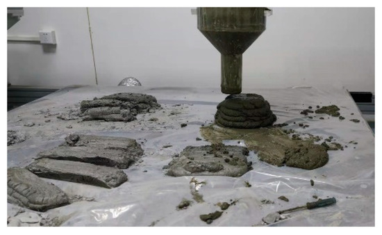
Figure 5.
Rheological test.
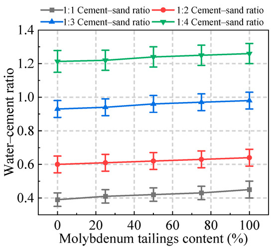
Figure 6.
Effect of different cement–sand ratio and molybdenum tailings contents on the water–cement ratio.
3.1.2. Influence of Printing Parameters on the Rheological Properties of 3D-Printed Concrete
Figure 7 depicts the appearance of specimens printed with different material parameters (cement–sand ratios), while printing process parameters are also critical variables influencing the rheological properties of 3D-printed concrete. The rheological characteristics post-extrusion are influenced by factors such as equipment type, screw shape, nozzle design, and extrusion flow rate [28]. Figure 8 presents the printed mortar specimens under controlled variations in nozzle height, screw rotation speed, and movement speed; specifically, group A represents specimens at different heights above the printing platform, group B represents specimens with varying nozzle rotation speeds, and group C represents specimens with different nozzle movement speeds. This study systematically investigates the control mechanisms of printing height, screw rotation speed, and nozzle movement speed on the 3D printing results. The experimental results show that with a 30 mm nozzle diameter, a movement speed of 1500 mm/min, and a rotation speed of 300 rad/min, increasing the nozzle height from 20 mm to 40 mm leads to a significant decrease in printing width, while the printing height only slightly increases (as shown in Figure 9a). This effect is primarily due to the reduced extrusion pressure and greater gravitational influence at higher nozzle heights. When the nozzle diameter is fixed at 20 mm, the printing height at 20 mm, and the movement speed at 3500 mm/min, increasing the rotation speed from 300 rad/min to 600 rad/min results in a simultaneous increase in both printing width and height (as shown in Figure 9b). This outcome is due to the increased extrusion rate caused by the higher rotation speed. With a 30 mm nozzle diameter, a printing height of 30 mm, and a rotation speed of 300 rad/min, increasing the movement speed from 1500 mm/min to 3500 mm/min significantly decreases the printing width, while the height remains relatively stable (as shown in Figure 9c). This is primarily related to the reduced material output per unit time at higher movement speeds. The above findings reveal how printing parameters influence the quality of 3D printing, providing a theoretical foundation for optimizing the printing process.
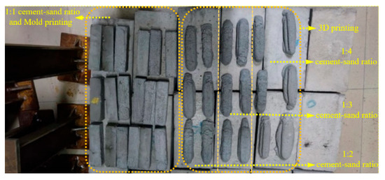
Figure 7.
Three-dimensionally printed mortar blocks with different cement–sand ratios.
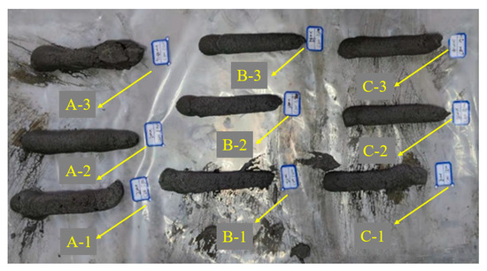
Figure 8.
Determination of printing parameters.

Figure 9.
Influence of printing process parameters on printing width and height. (a) Effect of different heights from the printing table on printing width and height. (b) Effect of different rotation speeds on printing width and height. (c) Effect of different movement speeds on printing width and height.
3.2. Mechanical Properties
3.2.1. Experimental Analysis of the Mechanical Properties of 3D-Printed Molybdenum Tailings Mortar
In this experiment, the mechanical properties of the mortar specimens cured for 28 days were tested using a DY-series pressure testing machine. Figure 10a displays the precise molded morphology of form-printed specimens, while Figure 10b shows the characteristic layered features of free-printed specimens. The flexural and compressive strengths under different strength grades and dosages were determined, and the effects of mold printing versus free printing methods on mechanical properties were analyzed. The testing procedures followed the standard procedure specifications for ordinary mortars, with the specimens placed on the flexural pressure table. The testing procedures followed the standard specifications for ordinary mortars, with the specimens placed on both the flexural and compressive testing machines. The flexural and compressive strengths of specimens with different mix ratios were measured, and the mean values of three specimens were calculated as the final results.

Figure 10.
Different printing methods.
3.2.2. Flexural Strength Analysis of 3D-Printed Molybdenum Tailings Mortar
Before analyzing the flexural strength of mortar with different mix proportions, it should be noted that the water–cement ratio varied with cement–sand ratios and molybdenum tailings contents, as illustrated in Figure 5. The increase in water demand with higher tailings content led to a higher water–cement ratio, which likely contributed to the reduction in flexural strength—particularly in mixes with lower cement content—due to increased porosity and a weaker interfacial transition zone.
As shown in Figure 11a, with the increase in the molybdenum tailings content, the flexural strength under different cement-to-sand ratios shows an overall trend of initial increase followed by a decrease, with an optimal content range of 20–60%. Among them, when the cement-to-sand ratio is 1:1, the flexural strength is consistently higher than that of other mix ratios, indicating that a higher cement content helps improve the mortar strength. This phenomenon may be attributed to the incorporation of an appropriate amount of fine molybdenum tailings, which can more effectively fill the internal pores of the cement paste, exerting a micro-aggregate filling effect [29] and resulting in a denser structure. In contrast, excessive addition of fine particles can dilute the cement, thereby affecting the overall hydration process and leading to a reduction in strength [30]. However, when the cement-to-sand ratio increases to 1:3 and 1:4, the difference in flexural strength between specimens becomes smaller, suggesting that the influence of the cement-to-sand ratio on flexural strength diminishes at lower ratios during the 3D printing process.
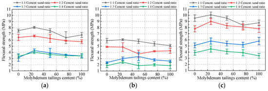
Figure 11.
Effects of different molybdenum tailings contents on flexural strength of mortar under various printing and casting methods. (a) Effect of different molybdenum tailings content on flexural strength of mortar under mold printing. (b) Effect of different molybdenum tailings content on flexural strength of mortar under free printing. (c) Effect of different molybdenum tailings content on flexural strength of mortar under traditional casting and vibration construction.
As shown in Figure 11b, with the increase in the molybdenum tailings content, the flexural strength for cement-to-sand ratios of 1:1 and 1:3 exhibits a trend of increasing first then decreasing, while for 1:2 and 1:4, it shows a trend of increasing, decreasing, and then increasing again, with the optimal content range being 20–60%. In all cases, the 1:1 cement-to-sand ratio yields consistently higher flexural strength, indicating that a higher cement content enhances the mortar’s mechanical performance. At cement-to-sand ratios of 1:3 and 1:4, the differences in flexural strength are minimal, and the influence trend of molybdenum tailings content is similar to that observed in mold-printed specimens. However, for the 1:2 cement-to-sand ratio, a notable drop in flexural strength occurs at the intermediate stage, suggesting potential effects from curing conditions or experimental errors.
As shown in Figure 11c, with the increase in the molybdenum tailings content, the flexural strength for 1:2 and 1:4 cement-to-sand ratios exhibits a trend of first increasing and then decreasing, while for 1:3, the trend is increasing, decreasing, then increasing again. This suggests that the strength variations in these tests may be attributed to external factors, such as curing conditions or measurement inconsistencies. The optimal molybdenum tailings content range remains 20–60% across all three test groups. Among them, the 1:1 cement–sand ratio consistently demonstrates the highest flexural strength values across most tailings content levels, supporting the conclusion that higher cement content improves strength, while the 1:2 ratio maintains more stable performance within the optimal 20–60% tailings content range.
Based on the data presented above, the variation trend of the flexural strength of 3D-printed molybdenum tailings mortar is similar to that of ordinary molybdenum tailings mortar. The flexural strength increases with the increase in binder content, and as the molybdenum tailings content rises, the strength first increases and then decreases, with the optimal dosage being approximately 20% to 60%.
As shown in Figure 12, the flexural strength of ordinary mortar (traditionally cast and vibrated), mold-printed mortar, and free-printed mortar with varying molybdenum tailings content was compared at cement-to-sand ratios of 1:1, 1:2, 1:3, and 1:4. The results show that the flexural strength of all three specimen types gradually decreases with increasing molybdenum tailings content.
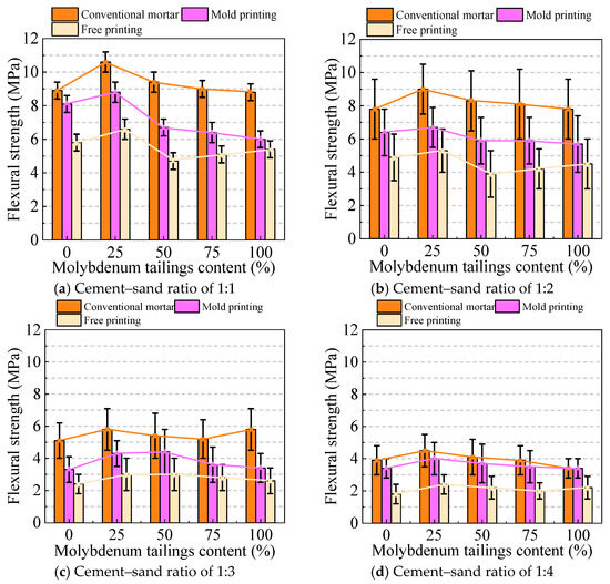
Figure 12.
Comparison of flexural strength at different cement–sand ratios under different printing methods.
As shown in Figure 13, the flexural strength of ordinary mortar (conventional cast and vibrated), mold-printed mortar, and free-printed mortar with molybdenum tailings contents of 0%, 25%, 50%, 75%, and 100% was compared across different cement-to-sand ratios. The results indicate that, as the cement-to-sand ratio decreases, the flexural strength of all three specimen types exhibits a decreasing trend.
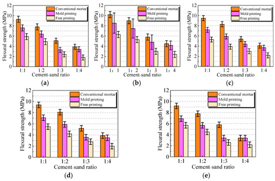
Figure 13.
Comparison of flexural strength at different molybdenum tailings contents under different printing methods. (a) 0% molybdenum tailings content; (b) 25% molybdenum tailings content; (c) 50% molybdenum tailings content; (d) 75% molybdenum tailings content; (e) 100% molybdenum tailings content.
The analysis of Figure 12 and Figure 13 reveals the following trend in flexural strength: ordinary mortar > mold-printed mortar > free-printed mortar. Specifically, across all mix ratios, the flexural strength of mold-printed mortar ranges from approximately 65% to 85% of that of ordinary mortar, while free-printed mortar ranges from 45% to 65% of the strength of ordinary mortar. This is because the water content of ordinary mortar is lower than that of 3D-printed mortar, and it undergoes vibration and mixing, resulting in higher strength. Although mold-printed mortar does not undergo vibration, its better molding quality results in higher strength compared to free-printed mortar. Moreover, under identical conditions, as molybdenum tailings content increases, the flexural strength of all three mortar types gradually decreases. The rate of flexural strength decline slows with changing cement-to-sand ratios, indicating that cement content has a greater influence on flexural strength than variations in molybdenum tailings content.
3.2.3. Compressive Strength Analysis of 3D-Printed Molybdenum Tailings Mortar
Similarly to the flexural strength, the compressive strength was also influenced by variations in the water/cement ratio. As shown in Figure 5, the required water/cement ratio increased with higher molybdenum tailings content, which partly explains the general decline in compressive strength at high replacement levels.
As shown in Figure 14a, with the increase in molybdenum tailings content, the compressive strength of the mortar also increases as the cement-to-sand ratio increases. The difference in compressive strength shows a significant variation at cement-to-sand ratios of 1:2 and 1:3. Under different molybdenum tailings contents, the molybdenum tailings content in the 1:1 and 1:2 mix ratios is relatively low, so its impact on compressive strength is limited. However, the maximum compressive strength still corresponds to a molybdenum tailings content between 20% and 60%. This optimal range is consistent with the findings of Quan et al. [19], who reported that, in conventional molybdenum tailings concrete, a 60% replacement rate led to a mechanical strength reduction of less than 10%. This indicates that, whether in traditional casting or 3D printing processes, there exists a replacement range that maximizes the densification of the microstructure.

Figure 14.
Effect of different molybdenum tailings contents on the compressive strength of mortar: comparison of mold printing, free printing, and traditional casting with vibration. (a) Influence of different molybdenum tailings contents on the compressive strength of mortar produced with mold printing. (b) Influence of different molybdenum tailings contents on the compressive strength of mortar produced with free printing. (c) Influence of different molybdenum tailings contents on the compressive strength of mortar in traditional casting and compaction construction.
As shown in Figure 14b, with the increase in molybdenum tailings content, the compressive strength under cement-to-sand ratio of 1:1, 1:3, and 1:4 exhibits a general trend of initially increasing and then decreasing, whereas the compressive strength under a 1:2 cement-to-sand ratio shows a trend of increasing, followed by a decrease, and then increasing again. The optimal molybdenum tailings content for all cement-to-sand ratios falls within the range of 20% to 60%. Among them, the compressive strength under the 1:1 cement-to-sand ratio is generally higher than that of other ratios, indicating that a larger cement-to-sand ratio helps to improve the compressive strength of the mortar.
As shown in Figure 14c, as the cement-to-sand ratio increases, the compressive strength of the specimens also increases, indicating that the amount of cementitious materials significantly affects the mortar’s compressive strength. Additionally, the optimal molybdenum tailings content for all four experiment groups falls within the range of 20% to 60%. The 1:1 cement–sand ratio demonstrates the highest compressive strength with the most stable performance across the entire range of tailings content, further confirming that higher cement content leads to greater and more consistent mortar strength.
In summary, the trend of compressive strength variation in 3D-printed molybdenum tailings mortar is similar to that of conventionally cast molybdenum tailings mortar. The compressive strength increases with the amount of binder, and as the molybdenum tailings content increases, the strength exhibits a trend of first increasing and then decreasing, with the optimal content ranging from approximately 20% to 60%.
As shown in Figure 15, the compressive strength of ordinary mortar (traditional casting and compaction construction mortar), mold-printed mortar, and free-printed mortar under different molybdenum tailings contents at cement-to-sand ratios of 1:1, 1:2, 1:3, and 1:4 is compared. The results show that the compressive strength of the three types of specimens gradually decreases with increasing molybdenum tailings content. This is primarily attributed to insufficient mold filling during the printing process. Additionally, as seen in the figure, the compressive strength of mold-printed and free-printed mortar differs significantly from that of ordinary mortar.
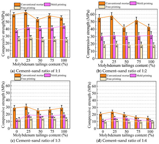
Figure 15.
Comparison of compressive strength under different cement-to-sand ratios for different printing methods.
As shown in Figure 16, a comparison was made between ordinary mortar (conventional cast-in-place mortar), mold-printed mortar, and free-printed mortar under different cement-to-sand ratios, with molybdenum tailings contents of 0%, 25%, 50%, 75%, and 100%. The results indicate that, under varying cement-to-sand ratios, the compressive strength of all three types of specimens gradually decreased.
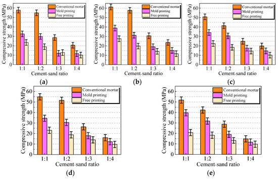
Figure 16.
Comparison of compressive strength of mortar with different molybdenum tailings contents under different printing methods. (a) 0% molybdenum tailings content; (b) 25% molybdenum tailings content; (c) 50% molybdenum tailings content; (d) 75% molybdenum tailings content; (e) 100% molybdenum tailings content.
The analysis of Figure 15 and Figure 16 reveals that, under different production methods, the compressive strength of ordinary mortar is significantly higher than that of 3D-printed mortar, and the compressive strength of mold-printed mortar is higher than that of free-printed mortar. Specifically, when considering all mix ratios including 1:1, the compressive strength of mold-printed mortar ranges from approximately 50% to 75% of that of ordinary mortar, while that of free-printed mortar ranges from 30% to 55%. This result is comparable to the range of anisotropic strength loss (approximately 40–70%) reported by Panda et al. [31] for 3D-printed fiber-reinforced materials, further confirming that the layered structure induced by the printing process is a key factor contributing to strength reduction. In addition, from the perspective of different production methods, this phenomenon can also be attributed to the lower water content in ordinary mortar compared with 3D-printed mortar, as well as the vibration and mechanical compaction applied during its formation, which together enhance its strength. Although mold-printed mortar does not undergo vibration, its formwork-constrained shape results in better molding quality and higher strength compared to free-printed mortar. Additionally, it is observed that the decline in compressive strength is more pronounced than that in flexural strength. Under the same conditions, as the content of molybdenum tailings increases, the compressive strength of the three mortars generally decreases, and the rate of strength decline gradually diminishes with varying water–cement ratios.
3.3. Anisotropic Properties
The interlayer weak interfaces caused by the 3D printing stacking process are one of the key factors hindering the engineering application of 3D-printed concrete (3DPC), and its mechanical properties often exhibit significant anisotropy [32,33,34,35]. It is important to note that anisotropy and heterogeneity describe materials from different perspectives and should not be conflated. Due to the structural differences between layers in the 3D-printed mortar during the printing process, significant anisotropy occurs [36]. To quantitatively characterize the anisotropy of 3D-printed specimens, this study introduces a new coefficient, A, to describe anisotropy. The specific calculation formula is shown in Equation (4).
is the load applied parallel to the printing direction; is the load applied perpendicular to the printing direction.
This study uses 3D-printed mortar with a cement-to-sand ratio of 1:1 and varying molybdenum tailings content. The flexural strength and compressive strength are measured by conducting tests under two different loading directions (as shown in Figure 17).
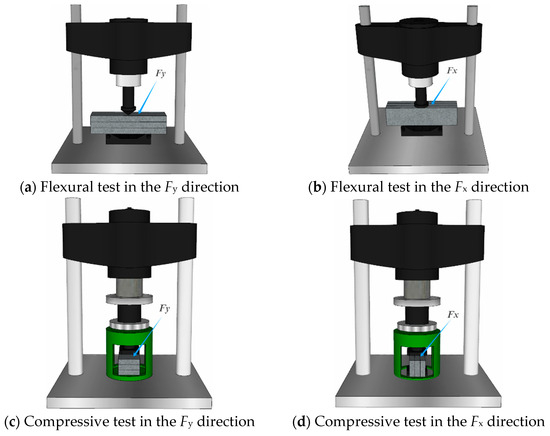
Figure 17.
Anisotropy testing process.
Based on the experimental results as shown in Figure 18, the anisotropy coefficient A indicates that the flexural strength did not exhibit significant variation between the two loading directions. This may be attributed to the fact that, during vertical and horizontal loading, the interlayer weak interfaces primarily experience tensile stress, and the direction of tensile stress is consistent with the printing interface, resulting in negligible anisotropy in flexural strength. In contrast, the compressive strength exhibited significant differences between the two directions, with a coefficient A value of approximately 0.20. This phenomenon is likely related to the stress distribution between the printing layers. When the loading direction is vertical, the failure force acts perpendicular to the interlayer interface and is compressive, making the interface less prone to failure. However, when the loading direction is horizontal, the force direction aligns with the interlayer interface, causing compression between the layers and weakening the interface, leading to lateral deformation and making the specimen more prone to failure. Therefore, the vertical compressive strength is greater than the horizontal compressive strength.
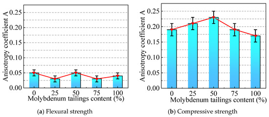
Figure 18.
Anisotropy of flexural and compressive strengths.
3.4. Ecological and Economic Analysis
As shown in Table 5, the GWP, AP, and CED of molybdenum tailings sand are all zero, indicating its excellent environmental performance. This completely avoids the carbon emissions (1.06 × 10⁻³ kg CO2/kg), acidification potential (6.57 × 10⁻⁶ kg SO2/kg), and cumulative energy demand (0.022 MJ/kg) associated with the extraction and processing of natural sand, making it a more sustainable aggregate choice. From an economic perspective, the use of molybdenum tailings as a full replacement for natural sand can reduce material costs, since the tailings are generally provided free of charge by mining enterprises, whereas the local market price of natural sand is approximately 0.021 USD/kg. In this study, the potential cost reduction is evaluated by calculating the total material cost of concrete per unit volume based on the mix design and material consumption, treating the cost of molybdenum tailings as zero. This approach allows a consistent comparison between conventional concrete and concrete using molybdenum tailings, highlighting the economic benefits associated with raw material substitution [16]. Meanwhile, the template-free 3D printing technology achieves significant breakthroughs in the formwork system, with GWP, AP, and CED all equal to zero, outperforming conventional formwork. By directly shaping concrete, the production, transportation, and removal of formwork are eliminated, which not only reduces resource consumption and waste generation but also simplifies the construction process. Therefore, the combination of molybdenum tailings and 3D printing technology, through both material substitution and process innovation, effectively promotes the green transformation of the construction industry.

Table 5.
Life cycle assessment data.
4. Conclusions
This systematic investigation reveals the application potential, mechanical characteristics, environmental performance, and economic advantages of molybdenum tailings in 3D-printed mortar. Through rheological testing, mechanical performance evaluation, anisotropy analysis, environmental impact assessment, and economic benefit analysis, this study establishes quantitative relationships among material proportions, printing parameters, and performance indicators, while demonstrating the significant advantages of molybdenum tailings in reducing environmental impacts and material costs. The main findings are summarized as follows:
- (1)
- The study of rheological properties indicates that mortar with a cement-to-sand ratio of 1:1 to 1:2 exhibits good printability, while mortar with ratios of 1:3 and 1:4 shows poor printing results. Under fixed nozzle diameter, movement speed, and rotation speed, increasing the nozzle height above the print bed leads to a decrease in print width, with little effect on print height. When the nozzle rotation speed increases, both the print width and height increase significantly; however, an increase in nozzle movement speed results in a decrease in print width, with limited impact on height.
- (2)
- The mechanical performance test results show that the flexural strength of conventional mortar is superior to that of mold-printed mortar, which in turn is higher than that of free-printed mortar, with strengths ranging from 70% to 80% and 45% to 60%, respectively, compared to conventional mortar. The compressive strength exhibits a similar pattern, with mold-printed and free-printed mortars showing strengths of 55% to 75% and 35% to 55%, respectively, compared to conventional mortar. Increasing molybdenum tailings content leads to a decrease in both flexural and compressive strength, but the variation in cement-to-sand ratio has a more significant impact on strength.
- (3)
- The anisotropy analysis reveals no significant difference in flexural strength under different loading directions, which may be due to the fact that the interlayer weak interface primarily experiences tensile stress in both loading directions. In contrast, compressive strength exhibits a clear anisotropic behavior, with the compressive strength in the X direction approximately 70% of that in the Y direction, resulting in an anisotropy coefficient (A) of about 0.20. This difference arises from the relative orientation of the loading direction to the interlayer interface: vertical loading applies pressure perpendicular to the interface, making it less prone to failure, whereas horizontal loading applies pressure parallel to the interface direction, inducing interlayer compression and lateral deformation, making the specimen more susceptible to failure.
- (4)
- Life cycle assessment demonstrates that molybdenum tailings sand exhibits zero global warming potential (GWP), acidification potential (AP), and cumulative energy demand (CED), completely avoiding the environmental impacts associated with natural sand extraction and processing. The template-free 3D printing technology further eliminates formwork-related environmental burdens, effectively reducing resource consumption and construction-phase environmental impacts. Economic analysis confirms that the complete replacement of natural sand with molybdenum tailings significantly reduces material costs since the tailings are typically provided without charge by mining enterprises. Consequently, the synergistic application of molybdenum tailings and 3D printing technology presents a viable pathway for environmentally sustainable and economically feasible construction, substantially supporting the green transformation of the industry.
4.1. Limitations
This study conducted a fundamental investigation into the properties of 3D-printed molybdenum tailings mortar at the laboratory scale; however, several limitations remain for potential engineering applications: (1) For large-scale structural components, printing parameters such as interlayer bonding performance and extrusion velocity may require further optimization under practical engineering conditions. (2) As an industrial byproduct, molybdenum tailings exhibit regional variations in composition and physical properties, which may affect the consistency of material performance. (3) The durability of printed components under complex environmental conditions (e.g., freeze–thaw cycles and sustained loading) requires further study. In addition, although this work highlights the environmental benefits of replacing natural river sand with molybdenum tailings, potential environmental and health risks from heavy metal leaching and dust emissions during material processing and use should be systematically assessed. Long-term monitoring of the stability of heavy metal immobilization under service conditions should be carried out to ensure compliance with safety requirements. Furthermore, the practical application of tailings-based materials in the construction industry must comply with relevant regulations and standards. Future research should integrate these regulatory frameworks into experimental design to ensure that the proposed material meets both technical performance and environmental safety requirements.
4.2. Future Perspectives
While this study has established fundamental understanding of 3D-printed molybdenum tailings mortar, several promising research directions remain for practical applications: (1) development of quality control standards for molybdenum tailings from different sources to ensure material consistency; (2) optimization of printing parameters for large-scale structural components through more innovative experimental approaches; (3) comprehensive durability assessment under combined environmental and mechanical loading conditions; (4) integration with digital construction technologies to achieve automated quality monitoring during the printing process. Future research should further investigate hybrid material systems combining molybdenum tailings with other industrial byproducts to enhance performance while maximizing sustainability benefits. These advancements will facilitate the transition of this innovative construction material from laboratory research to industrial applications.
Author Contributions
Conceptualization, S.G.; methodology, J.Y.; software, T.L.; validation, S.G., T.N. and Z.H.; formal analysis, T.L.; investigation, J.Y.; resources, T.N.; data curation, T.L.; writing—original draft preparation, T.L.; writing—review and editing, S.G., T.N. and Z.H.; visualization, Z.H.; supervision, S.G.; project administration, S.G.; funding acquisition, S.G. All authors have read and agreed to the published version of the manuscript.
Funding
The project is supported by the Natural Science Basic Research Program of Shaanxi Province (Program No. 2024JC-YBMS-439 and 2025JC-YBMS-635), the National Natural Science Foundation of China (52411540027), and the Scientific Research Program for Youth Innovation Team of Shaanxi Provincial Department of Education (24JP201).
Data Availability Statement
Data available on request from the authors.
Conflicts of Interest
The authors declare no conflict of interest.
References
- AI-Tamimi, A.K.; Alqamish, H.H.; Khaldoune, A.; Alhaidary, H.; Shirvanimogaddam, K. Framework of 3D concrete printing potential and challenges. Buildings 2023, 13, 827. [Google Scholar] [CrossRef]
- Ma, L.Z.; Yin, D.S.; Ren, J.T.; Tian, M.; Chen, X.; Li, L. An effective thixotropic structural dynamics rheological model for 3D printed concrete materials in the flow state. Constr. Build. Mater. 2024, 447, 138215. [Google Scholar] [CrossRef]
- Zhao, Y.M. Preparation and Performance Study of Ultra-High Performance Concrete Based on 3D Printing. Master’s Thesis, Shandong Jianzhu University, Jinan, China, 2022. [Google Scholar]
- Wang, X.P. Close Packing Theroy Based Design Method in Developing Eco-Efficient Ultra-High Performance Concrete. Ph.D. Thesis, Wuhan University of Technology, Wuhan, China, 2018. [Google Scholar]
- Van Damme, H. Concrete material science: Past, present, and future innovations. Cem. Concr. Res. 2018, 112, 5–24. [Google Scholar] [CrossRef]
- Yan, G.H. Mechanical and Shrinkage Properties of Acid Activated Cement-Based Materials. Master’s Thesis, China University of Mining and Technology, Xuzhou, China, 2018. [Google Scholar]
- Ukpata, J.O.; Ephraim, M.E.; Akeke, G.A. Compressive strength of concrete using lateritic sand and quarry dust as fine aggregate. ARPN J. Eng. Appl. Sci. 2012, 7, 81–92. [Google Scholar]
- Zhang, F.; Lu, Z.; Wang, D. Working and mechanical properties of waste glass fiber reinforced self-compacting recycled concrete. Constr. Build. Mater. 2024, 439, 137172. [Google Scholar] [CrossRef]
- Pilegis, M.; Gardner, D.; Lark, R. An investigation into the use of manufactured sand as a 100% replacement for fine aggregate in concret. Materials 2016, 9, 440. [Google Scholar] [CrossRef]
- Gao, S. Life cycle sustainability assessment of concrete-filled steel tubular frames in earthquake regions. Eng. Struct. 2025, 328, 119761. [Google Scholar] [CrossRef]
- Cui, X.W.; Di, Y.Q.; Pang, H.; Nan, N.; Liu, X.; Zhou, C.S. Research on preparation of high performance concrete with molybdenum tailings. Met. Mine 2017, 7, 193–196. [Google Scholar]
- Gao, S.; Zhao, G.H.; Guo, L.H.; Zhou, L.; Cui, X.; Yang, H. Mechanical properties of circular thin-tubed molybdenum tailing concrete stubs. Constr. Build. Mater. 2021, 268, 121215. [Google Scholar] [CrossRef]
- Gao, S.; Li, W.; Yuan, K.K.; Rong, C. Properties and application of thixotropic cement paste backfill with molybdenum tailings. J. Clean. Prod. 2023, 391, 136169. [Google Scholar] [CrossRef]
- Lin, S.C.; Liu, H.B.; Bai, Q. Bond Behavior of Concrete-Filled Steel Tube with Molybdenum Tailing. Int. J. Steel Struct. 2024, 24, 354–365. [Google Scholar] [CrossRef]
- Lin, S.C.; Bai, Q. Experimental study and numerical simulation on shear behavior of steel and concrete composite beam with molybdenum tailing. Structures 2023, 57, 105230. [Google Scholar] [CrossRef]
- Gao, S.; Cui, X.W.; Kang, S.B.; Ding, Y. Sustainable applications for utilizing molybdenum tailings in concrete. J. Clean. Prod. 2020, 266, 122020. [Google Scholar] [CrossRef]
- Yuan, J.; Bai, Q.; Gao, S.; Wang, Y.; Yu, S. Uniaxial compressive stress-strain model of Molybdenum tailings concrete after high-temperature exposure. Constr. Build. Mater. 2024, 428, 136343. [Google Scholar]
- Gao, S.; Li, J.Q.; Nishiwaki, T.; Ding, Y.; Wang, J.X. Structural implementation of recycled lump prepared from waste concrete after elevated temperatures: Mechanical and environmental performances. Structures 2024, 67, 106970. [Google Scholar] [CrossRef]
- Quan, X.Y.; Wang, S.L.; Liu, K.N.; Xu, J.; Zhao, N.; Liu, B. Evaluation of molybdenum tailings as replacement for fine aggregate in concrete: Mechanical, corrosion resistance, and pore microstructural characteristics. Constr. Build. Mater. 2022, 343, 127982. [Google Scholar] [CrossRef]
- Luo, T.; Yi, Y.; Sun, Q.; Li, L.G.; Tang, L.; Hua, C. The effects of adding molybdenum tailings as cementitious paste replacement on the fluidity, mechanical properties and micro-structure of concrete. J. Build. Eng. 2022, 62, 105377. [Google Scholar] [CrossRef]
- JGJ/T 98-2010; Specification for Mix Proportion Design of Masonry Mortar. Ministry of Housing and Urban-Rural Development of the People’s Republic of China: Beijing, China, 2011.
- JGJ/T 70-2009; Standard for Test Method of Basic Properties of Construction Mortar. Ministry of Housing and Urban-Rural Development of the People’s Republic of China: Beijing, China, 2009.
- GB/T 2419-2005; Test Method for Fluidity of Cement Mortar. General Administration of Quality Supervision, Inspection and Quarantine of the People’s Republic of China: Beijing, China; Standardization Administration of the People’s Republic of China: Beijing, China, 2005.
- Li, T.; Li, Q. Review on mechanical properties of building 3D printing. China Build. Mater. Sci. Technol. 2022, 31, 44–48. [Google Scholar] [CrossRef]
- Bundesverband der Deutschen Ziegelindustrie e. V. (Ed.) Green Building Challenge Handbuch; Bundesverband der Deutschen Ziegelindustrie e. V.: Bonn, Germany; Available online: http://www.ziegel.at/gbc_ziegelhandbuch/default.htm. (accessed on 31 October 2013).
- Müller, H.S.; Haist, M.; Vogel, M. Assessment of the sustainability potential of concrete and concrete structures considering their environmental impact, performance and lifetime. Constr. Build. Mater. 2014, 67, 321–337. [Google Scholar] [CrossRef]
- Balasbaneh, A.T.; Sher, W.; Ibrahim, M.H.W. Life cycle assessment and economic analysis of Reusable formworkmaterials considering the circular economy. Ain Shams Eng. J. 2024, 15, 102585. [Google Scholar] [CrossRef]
- Zhang, L.Q.; Guo, M.Z.; Li, H.Y.; Han, B.G. A review of rheological properties and influencing factors of 3D printed concrete. Acta Mater. Compos. Sin. 2024, 41, 5754–5782. [Google Scholar]
- Zheng, X. Influence of Powder Particles on Flow Characteristics of Ultra-high Performance Concrete. Master’s Thesis, Chongqing University, Chongqing, China, 2021. [Google Scholar]
- Ding, M.; Yu, R.; Feng, Y.; Wang, S.; Zhou, F.; Shui, Z.; Gao, X.; He, Y.; Chen, L. Possibility and advantages of producing an ultra-high performance concrete (UHPC) with ultra-low cement content. Constr. Build. Mater. 2021, 273, 122023. [Google Scholar] [CrossRef]
- Panda, B.; Paul, S.C.; Tan, M.J. Anisotropic mechanical performance of 3D printed fiber reinforced sustainable construction material. Mater. Lett. 2017, 209, 146–149. [Google Scholar] [CrossRef]
- Rahul, A.V.; Santhanam, M.; Meena, H.; Ghani, Z. Mechanical characterization of 3D printable concrete. Constr. Build. Mater. 2019, 227, 116710. [Google Scholar] [CrossRef]
- Mechtcherine, V.; Nerella, V.N.; Will, F.; Näther, M.; Otto, J.; Krause, M. Large-scale digital concrete construction-CONPrint3D concept for on-site, monolithic 3D-printing. Autom. Constr. 2019, 107, 102933. [Google Scholar] [CrossRef]
- Liu, B.; Liu, X.Y.; Li, G.; Geng, S.; Li, Z.; Weng, Y.; Qian, K. Study on anisotropy of 3D printing PVA fiber reinforced concrete using destructive and non-destructive testing methods. Case Stud. Constr. Mater. 2022, 17, e01519. [Google Scholar] [CrossRef]
- Jiang, Q.; Liu, Q.; Wu, S.; Zheng, H.; Sun, W. Modification effect of nanosilica and polypropylene fiber for extrusion-based 3D printing concrete: Printability and mechanical anisotropy. Addit. Manuf. 2022, 56, 102944. [Google Scholar] [CrossRef]
- Wu, W.H.; Luo, S.R.; Ou, X.; Wang, D.H.; Huang, H. Effect of mineral admixtures on mechanical anisotropy of 3D printed cement-based materials. J. Fuzhou Univ. (Nat. Sci. Ed.) 2023, 51, 286–292. [Google Scholar]
Disclaimer/Publisher’s Note: The statements, opinions and data contained in all publications are solely those of the individual author(s) and contributor(s) and not of MDPI and/or the editor(s). MDPI and/or the editor(s) disclaim responsibility for any injury to people or property resulting from any ideas, methods, instructions or products referred to in the content. |
© 2025 by the authors. Licensee MDPI, Basel, Switzerland. This article is an open access article distributed under the terms and conditions of the Creative Commons Attribution (CC BY) license (https://creativecommons.org/licenses/by/4.0/).