Article

Performance Evaluation of Conventional and Recycled Ballast Materials: A Coupled FDM-DEM Approach Considering Particle Breakage

by
Juan Manuel Mayoral
* and
Nohemí Olivera
Geotechnical Department, Institute of Engineering, National University of Mexico, Mexico City 04510, Mexico
*
Author to whom correspondence should be addressed.
Appl. Sci. 2025, 15(21), 11460; https://doi.org/10.3390/app152111460
Submission received: 26 September 2025 / Revised: 17 October 2025 / Accepted: 24 October 2025 / Published: 27 October 2025

Abstract

The ballast consists of angular particles whose main function is to transmit and distribute train loads to the soil. However, under repeated loads, these particles wear down and break, causing permanent settlement, reducing track stability, and increasing maintenance. Characterizing stresses and deformations under monotonic and cyclic loading is essential to predict short- and long-term performance of railway systems. This numerical study evaluates the behavior of improved ballast materials, considering particle breakage. A hybrid Finite Difference and Discrete Element model was used to simulate the multiscale response of the track system under realistic loading conditions. The model was calibrated using data from laboratory tests conducted by various researchers. The performance of conventional ballast was compared with alternative mixtures, analyzing vertical displacements, stress distribution, safety factor, and particle breakage rates. Results show that the basalt-rubber composite significantly enhances ballast performance by reducing settlements and subgrade stresses while improving resistance to particle breakage. The FDM-DEM coupled approach effectively captures micromechanical interactions and breakage mechanisms, offering valuable insights for optimizing track design based on quantifiable performance criteria. Overall, the findings indicate the hybrid model and breakage–contact criteria approximated system behavior, while alternative ballast compositions improved durability, reduced maintenance, and supported resilient railway solutions.

1. Introduction

The assessment of railway tracks has undergone significant changes in recent decades due to the need to support higher speeds and shaft loads and improve environmental sustainability. The track support transfers loads to the ground within capacity limits, preventing excessive settlements and lateral displacements [1]. Ballast has the structural function of absorbing and dissipating vertical forces from rail traffic, allowing rapid drainage of rainwater, and facilitating the correction of geometric defects [2].
Numerical studies analyzing stress changes in ballast due to train passages have provided a detailed understanding of load distribution patterns [3]. Liu and Zou [4] demonstrate that ballast abrasion significantly impacts strength and deformation. The three-dimensional stress state critically influences substructure design and service life, as the rotation of principal stresses accelerates the accumulation of plastic deformation. Train-induced cyclic loads also affect material stiffness and permanent deformation development [5,6]. Table 1 presents relevant research on track support analysis and evaluation, covering numerical modeling, laboratory and large-scale testing, field measurements, and proposals to improve railway design methods.
Studies such as [7] show that the parent rock’s strength determines its performance: higher values reduce settlement, increase stiffness, and decrease degradation (quantified by the Ballast Breakage Index, BBI) [8]. However, even the most resistant materials face challenges under repeated dynamic loads, driving the search for innovative alternatives and the pursuit of an optimal material.
A promising research line explores the use of recycled materials to comprise more sustainable substructures [9]. Previous studies have indicated that planar polymeric geogrids and cellular inclusions, such as geocells, have the potential to improve track stiffness and reduce lateral dilation [10,11,12]. Some recent studies have proposed using recycled materials, such as recycled glass, plastics, and demolished construction waste, to replace traditional aggregates in railway substructures. This approach aims to provide a more sustainable solution and meet the requirements outlined by standards [13,14,15].
Mixes of recycled rubber and steel slag have also been evaluated to improve mechanical properties [16], and in large-scale tests researchers have compared steel slag with conventional crushed ballast [17]. The results showed that steel slag ballast has a higher elastic modulus, less permanent deformation under heavy train loads, and greater shear resistance, consistent with the findings of Kaya [18] and Koh [19]. High-density slag can also enhance track stability by increasing lateral ballast resistance by 27% and vertical stiffness by 64% [20].
Rubber intermixed ballast systems (RIBS) are an innovative solution for railway ballast that combines rubber granules with conventional ballast aggregates [21]. Through large-scale testing, the optimal rubber particle size (9.5–19 mm) and an inclusion ratio (10%) were chosen to meet performance standards, while reducing long-term maintenance. The results show that this 10% rubber substitution significantly decreases degradation and fouling of the coarse aggregates [22].
For the assessment of long-term conditions, large-scale experiments with ballasted track have been designed to gain insight into the behavior of the track bed and the progression of ballast degradation [23]. These studies used validated physical model test platforms to examine settlement and degradation patterns under repeated train loadings. Artificial neural networks have also been incorporated into monitoring to develop simplified numerical models that relate measured parameters to degradation processes [24].
Despite advances in assessing the behavior of materials in the track support system, most laboratory studies do not reproduce the complexity of a real railway system. In these tests, degradation is accelerated through high loads and controlled conditions, which differ from the wear mechanisms observed in the field, where low-amplitude vibrations, localized impacts, and environmental variations influence them. Additionally, the dynamic interaction among the sleeper, ballast, and subgrade is often ignored, even though its effect is crucial in the actual distribution of stresses and the system’s response under load. Furthermore, none of the conventional methods have demonstrated an effective capacity to absorb energy and provide adequate damping and resilience to the rails, enabling them to withstand impacts and repeated loads in a sustained manner.
Table 1. Numerical and experimental studies on the assessment of railway tracks.
AuthorsResearchPrincipal Findings
Godson et al. [25]Large-scale tests were conducted to compare the physical, mechanical, and environmental performance of electric arc furnace slag (EAFS) with conventional material.The shear strength of EAFS was 15–22% higher than that of granite, with less final vertical deformation and a 20% increase in the load-bearing capacity of the granular layer. In addition, its leaching is within regulatory limits, making it safe for railway use.
Nasrollahi et al. [26]Real-time monitoring of a zone between a ballasted track and a slab track with fiber Bragg grating (FBG) sensors installed in situ.The FBG system reliably captures short- and long-term deformations/accelerations of the rail and sleeper; useful data for early diagnosis and model calibration.
Chen et al. [27]Diametral compression tests by size, large-scale triaxial tests, and numerical modeling using the Discrete Element Method (DEM), to access micromechanical indicators such as coordination number, contact forces, and anisotropy.The strength of ballast follows a Weibull distribution, and heterogeneous grading improves its performance, although large particles increase the risk of fracture.
Indraratna et al. [14]Evaluation of recycled material tests: CWRC 1, SEAL 2 (slag + CW + RC), tire cells, and UBM 3 under ballast.The recycled materials studied increase energy dissipation, reduce degradation, and vibrations.
Li et al. [28]Full-scale track testing on ballasted track: dynamic responses and cumulative settlements.They recorded vibration speeds, dynamic stresses, and settlement evolution under moving loads.
Sayeed and Shahin [29]A design method for ballasted railway track foundations is proposed, combining improved empirical models and 3D numerical analysis, capable of supporting high-speed trains and heavy loads.The new design method for railway foundations prevents critical failures using empirical models and 3D analysis, offering a more robust solution that is adaptable to various design conditions and modern railway traffic.
Edwards et al. [30]Laboratory and field tests on concrete sleepers using surface strain gauges to obtain bending moments.Non-invasive method that quantifies variability between sleepers and provides data for design/service life.
Lu and McDowell [31]The study uses the Discrete Element Method (DEM) to simulate the behavior of ballast under monotonic and cyclic loads, replicating shear strength and volumetric response, validated experimentally.The model shows that shear strength varies with confining pressure and ballast size, being less sensitive to pressure in small particles. The number of roughness features influences the peak friction angle, but not the residual friction angle.
Lim et al. [32]Compression tests were performed on six types of rock to analyze the strength of the ballast, evaluating the results with the Weibull distribution to explore the relationship between size and strength.The strengths of the ballast conform to the Weibull distribution, but the relationship between size and strength differs from the theory due to factors such as quarry processing and surface fractures, which limit the applicability of the model.
Li and Selig [33]A design method is proposed to determine the thickness of the granular layer between ballast and subballast, preventing subgrade failure due to repeated loads, using procedures that consider soil strength and railway load.The method converts traffic conditions into design parameters and defines two criteria to prevent failure and deformation. Validated in the field, it showed good results in tests and real sites.
Cundall and Strack [34]This research presents the Discrete Element Method (DEM) as a numerical tool designed to describe the mechanical behavior of assemblies of particles represented by disks or spheres.The numerical results showed a high degree of visual similarity with those obtained experimentally, which supported the validity of the DEM for investigating granular behavior.
1 Coal wash rubber crumbs. 2 Synthetic energy-absorbing layer. 3 Under ballast mat.
This study evaluates the performance of conventional materials against two sustainable and innovative alternatives for the railway track support system. A three-dimensional hybrid numerical model combining the Discrete Element Method (DEM) and Finite Difference Method (FDM) was developed and calibrated using large-scale triaxial test data. The model accounts for full interaction among track components (rail, sleeper, ballast, and subgrade) to accurately simulate structural response under dynamic conditions. A particle fracture criterion differentiates volume and contact effects, while a simplified angular-shape model with rolling resistance ensures a balance between accuracy and computational efficiency in evaluating sustainable materials for railway infrastructure.

2. Database

The properties of the five materials evaluated in this study, basalt, granite, limestone, steel slag, and a mixture of basalt and rubber (RIBS), are based on results reported in previous research by other authors. Table 2 summarizes the most relevant characteristics of the selected materials, including the values obtained in the Micro-Deval and Los Angeles abrasion resistance tests. Figure 1 shows the particle size distribution of each material, determined by particle size analysis in accordance with ASTM C136/C136M-19 [35]. This distribution was used directly to define the input particle size in the numerical models developed in this study.
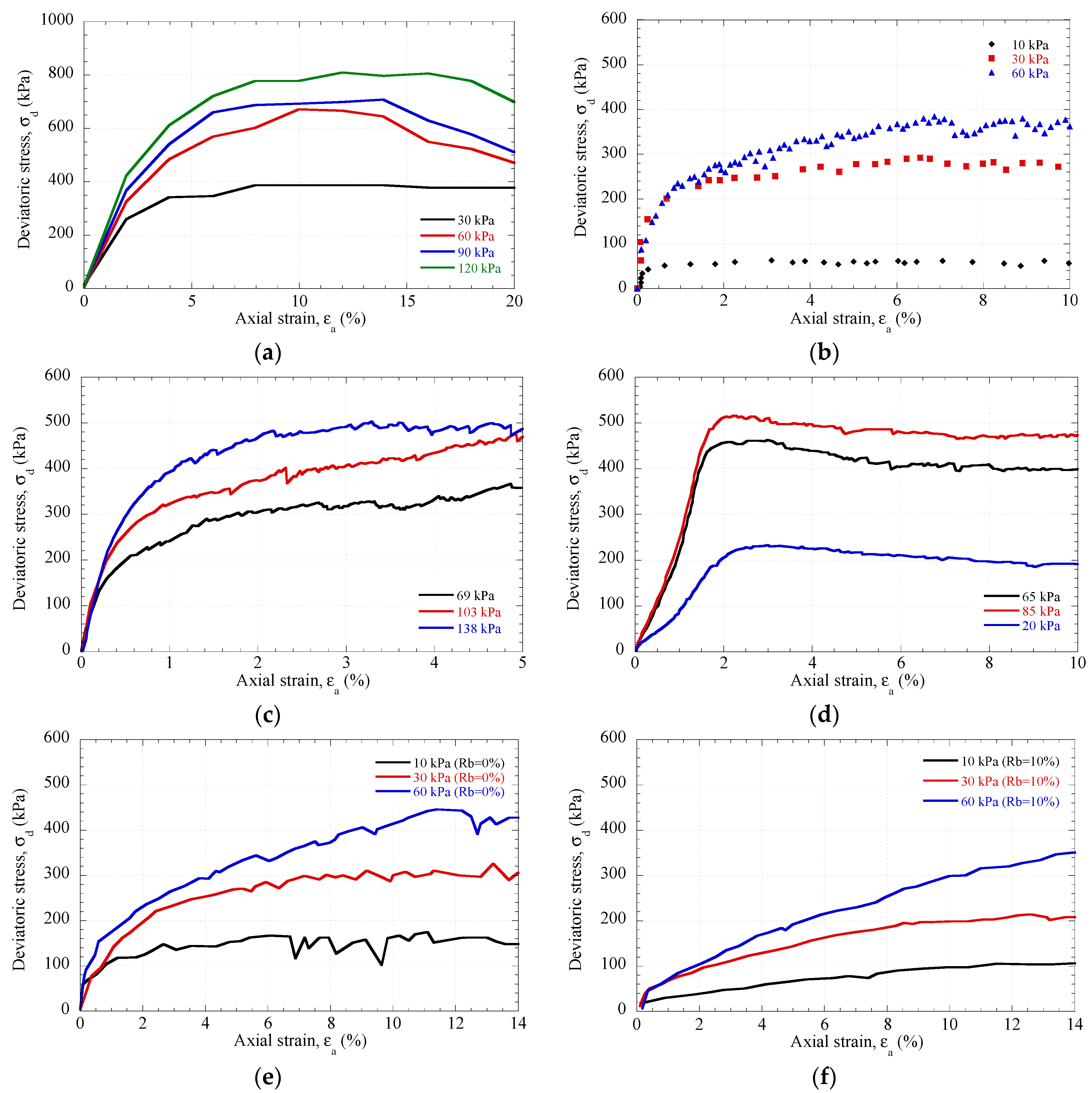
Figure 2, prepared from data reported in the technical literature, shows the stress–strain curves under different confinement levels for two materials. Steel slag exhibits a stiffer behavior, characterized by a well-defined peak strength, while the basalt-rubber mixture displays a more ductile response, with greater deformations before failure. Table 3 complements this information by including the specific values obtained from the corresponding experimental tests.
Railway ballast inherently exhibits sharp edges and angular corners that significantly influence track mechanics through increased sliding friction, enhanced rolling resistance, and improved particle interlocking. To capture these geometric properties (sphericity, angularity, texture), clumped-sphere aggregates are commonly employed [41]. While this approach effectively represents multi-contact interactions and realistic rolling resistance behavior [42], it requires a balance between geometric accuracy and computational efficiency for large-scale simulations.
The use of sphere aggregates to represent angular particles is a common simplification in DEM models, aimed at maintaining a balance between geometric fidelity and computational efficiency. While this approximation may partially underestimate the effects of interlocking and shear resistance, the rolling resistance contact model largely compensates for these limitations by reproducing the rotational stiffness and angular restriction mechanisms observed in real particles. Several studies [43,44,45] support the effectiveness of this strategy in adequately capturing the overall mechanical response of ballast without compromising computational cost.

3. Model Description

3.1. Rolling Resistance Contact Model

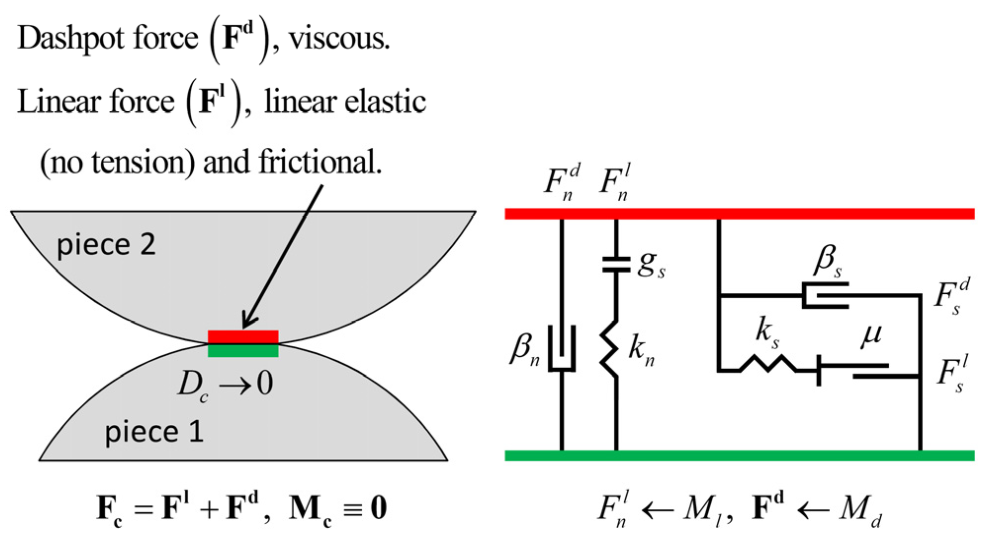
To address the issue above, the linear rolling resistance model implemented in PFC3D [45] was adopted as a reference. Particle interactions (particle-particle or particle-facet) are governed by contact forces with normal and shear components, both incorporating spring force ( F n s ) and a damping force ( F n d ). Notably, the normal spring force updates in absolute terms (independent of loading history), while the resultant normal force is limited to prevent tensile stresses. The normal component ( F n ) of the contact force follows:
F n = F n s + F n d = k n u n + β n u ˙ n 0  (No tension)
where k n is the normal contact stiffness, β n is the damping coefficient in normal direction, u n y u ˙ n are the absolute normal displacement and interparticle velocity, respectively, as shown in Figure 3.

3.2. Lineal Model

The Linear Contact Model (LCM), originally developed by Cundall and Strack [34], represents the fundamental contact formulation in DEM simulations. This model combines linear elastic stiffness and viscous damping components to govern energy transfer and dissipation in both normal and tangential directions. The linear component provides tension-free elastic behavior with frictional resistance, while the damping introduces viscous effects, both acting through an infinitesimal contact point that exclusively transmits forces without moments. As illustrated in Figure 4, the resultant contact force emerges from the superposition of these two components, where the elastic stiffness maintains a Hertzian-like contact response while the damping ensures energy dissipation during particle interactions.
For ballast materials, particle contacts exhibit negligible viscous behavior, rendering the damping component inactive in most scenarios. Consequently, PFC-based ballast studies typically omit dashpot considerations [46,47]. The linear component combines normal and shear forces as expressed in Equation (2) [48]:
F = F l + F d
F n l = k n β n
F n l = ( F n l ) 0 + k n δ n
F s l = ( F s l ) 0 k s δ s
where F n l and F s l are the normal and shear components of the linear force, k n and k s are the normal and shear stiffnesses, β n and β s are the normal and shear critical-damping ratios and, δ n and δ s are the adjusted relative normal and shear-displacement increment.
It should be noted that in most DEM models (using PFC) with the linear contact model, the kinetic energy of particles is dissipated through frictional sliding and local damping, with a default coefficient of 0.7. In PFC, local damping is considered a particle-level attribute, rather than a contact model parameter, and applies a damping force to each particle individually [48].

3.3. Breakage Particle

Railway ballast performance is critically influenced by particle breakage, which alters mechanical properties and track stability. Particle fracture resistance varies due to intrinsic defects, compositional variations, and loading conditions, typically modeled using Weibull distributions. Fractal dimension (D) quantifies fragmentation effects, increasing with progressive breakage and influencing load redistribution. However, excessive fine accumulation compromises drainage, requiring controlled fragmentation.
When studying the fracture of granular particles, it is necessary to define a failure criterion that determines when a particle breaks under specific mechanical conditions. Therefore, this study employs the criterion proposed by Ciantia et al. [49], which unifies contact and volume properties into a single mathematical expression.
The model establishes a limiting condition for normal contact forces, requiring that the force F must not exceed a critical threshold value F l i m , as expressed by the following equation:
F < κ f ( χ , υ ) π R 2 s i n 2 θ 0 = σ l i m A F = F l i m
The limiting strength σ l i m depends on material properties κ , χ y υ , while A F represents contact area, R is the sphere radius, and θ 0 is a solid angle ‘seen’ from the center of the particle. This separation between material strength ( σ l i m ) and contact geometry ( A F ) allows independent treatment of scenario-dependent contact properties versus intrinsic material behavior. The model accounts for natural soil variability and size effects, with σ l i m following a normal distribution (material-specific coefficient of variation). A Weibull-type size correction f s i z e ( d ) is applied, reflecting increased smaller-particle strength as a hardening rule rather than strict statistical relationship. The size-dependent strength is expressed as
σ l i m = σ l i m , 0 f s i z e ( d )
where f s i z e ( d ) is given by
f s i z e ( d ) = d d 0 3 m
where d 0 = 2 mm is the reference diameter and m is a material parameter. The factor f s i z e ( d ) scales the limiting strength with particle size, capturing the enhanced resistance of smaller particles. For contact area A F evaluation, a common approach treats the contact angle θ 0 as a material constant independent of σ l i m , yielding the failure contact area:
A F = π 4 d 2 s i n 2 θ 0
Simulations must incorporate mass loss during fragmentation to accurately model Particle Size Distribution (PSD) evolution. Studies [50,51] show fragmentation generates fractal particle distributions ( α ≈ 2.6), expressed as
M ( L < d ) M T = d 3 α d m i n 3 α d m a x 3 α d m i n 3 α
where M T is the total mass, M ( L < d ) is the smallest particle of d , d m a x is the maximum particle size and d m i n is the smallest particle observed.
Fragmentation simulations account for mass loss, producing fractal PSDs ( α ≈ 2.6). Apollonian packings (fractal dimension 2.47) model post-fragmentation placement, aligning particles with principal stresses. A minimum particle size threshold optimizes computational efficiency, with analyses showing comminution limits dominate PSD evolution over particle count (14-sphere configurations proving optimal), as shown in Figure 5.

4. Model Calibration

This section presents the methodology and results of the numerical simulations conducted to replicate triaxial test behavior using the Discrete Element Method (DEM). The obtained calibration parameters are introduced, ensuring the numerical model accurately captures the mechanical response observed in laboratory tests.
The calibration procedure for the simulated triaxial specimens is described in detail, including the adjustment of micromechanical parameters and validation against macroscopic experimental data. Additionally, the key features of the coupled modeling approach combining Finite Difference Method (FLAC3D) and Discrete Element Method (PFC3D) are discussed. This hybrid framework allows for the simulation of geotechnical problems involving both continuous and discontinuous media, enhancing the analysis of soil and rock mechanics under complex loading conditions.
The integration of PFC3D (for particle-scale interactions) and FLAC3D (for continuum modeling) provides a robust numerical tool for studying granular materials and their interaction with larger structural elements, offering insights that are difficult to obtain through purely experimental or analytical approaches.

4.1. Parameter Calibration

The model calibration was based on extensively documented and validated experimental results gathered from the technical literature, derived from carefully selected large-scale triaxial tests. These studies are in good agreement with the recommended properties for materials often used in railway tracks supports. Thus, these data were deemed appropriate for this initial research phase. While the importance of direct experimental validation is acknowledged, the used data allows establishing the soundness of the proposed methodology.
For the calibration process, large-scale triaxial tests previously reported by different authors [36,37,38,39,40] were reproduced numerically. Each simulation was designed to remain consistent with the laboratory configurations described in those studies, ensuring that the numerical response could be directly compared with the experimental results.
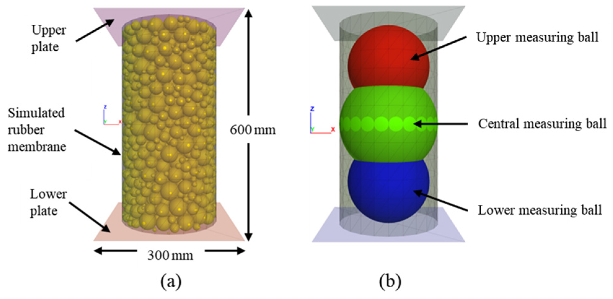
Triaxial tests were conducted using cylindrical specimens of different sizes and with a grain size distribution based on previous experimental data. Each specimen, enclosed by two flat plates and a curved wall (Figure 6), was created by randomly placing ballast particles and adjusting the friction coefficient to achieve either dense or loose packing. Isotropic confinement was applied using the PFC3D servo-control algorithm until the target pressure was reached.
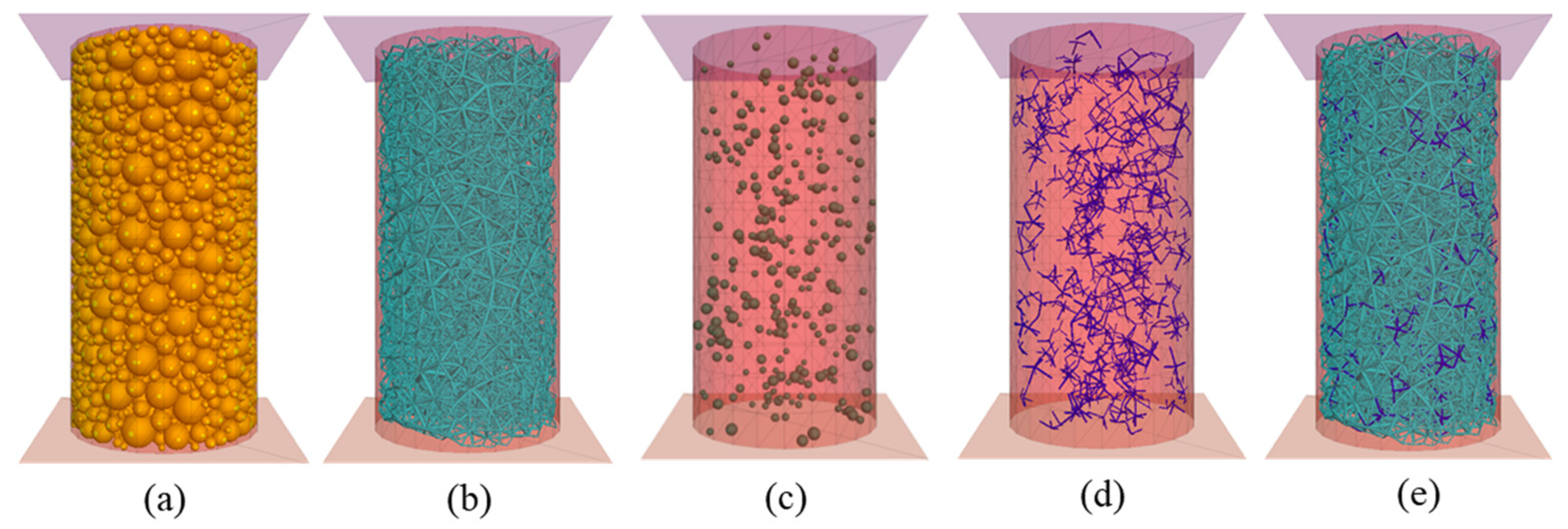
Once the sample was obtained, a monotonic triaxial test was conducted by controlling the axial deformation and maintaining constant lateral pressure. During loading, the deviatoric stress and axial deformation were recorded, and measurement spheres were used to assess particle breakage. In the model, three types of contact were considered: ballast–ballast, rubber–rubber, and ballast–rubber, as shown in Figure 7. Contacts with rubber were modeled using a linear approach, while ballast contacts were simulated with a linear model incorporating rolling resistance to account for the effect of angular shape and to reduce computational cost.
Due to the complexity of directly obtaining DEM simulation parameters from experimental results, most researchers have historically determined these parameters using indirect methods, which are described below and adopted in this study. In the first stage, a comprehensive literature review was conducted to establish reasonable value ranges for the parameters. Subsequently, these values were optimized through trial-and-error iterations to achieve agreement between the simulated macroscopic mechanical behavior and available experimental data. The final parameters used in the DEM simulations are specified in Table 4.
The selection of micro-parameters is a key aspect for achieving an accurate approximation in numerical simulation. Table 5 summarizes the values used in previous studies to represent the behavior of rubber, which served as a reference and starting point for the calibration developed in this study. The calibration procedure was conducted as follows:
First, the basalt-basalt contact parameters were calibrated using particles from a pure basalt sample. Subsequently, a 10% rubber-basalt mixture was employed to calibrate the rubber-basalt contact parameters. Given the established basalt-basalt contact parameters and the limited quantity of large rubber particles, the rubber-basalt contact was found to have minimal contribution to the overall strength. Therefore, specific calibration of the rubber-basalt contact parameters was performed. Finally, the rubber content percentage was varied to validate the simulated macroscopic behavior against available experimental data. The final micro-parameters adopted to represent the rubber are detailed in Table 6. Notably, following the recommendations of Li and McDowell [52], a local damping coefficient of 0.7 was implemented in the model. This technical measure proved crucial for suppressing numerically unstable oscillations in the system during simulations.
Table 5. Reference parameters for rubber.
Contact ModelNormal
Stiffness, kn
Shear
Stiffness, ks
Young
Modulus, E
Friction
Coefficient, μ
Rolling Friction Coefficient, μrReference
(N/m)(N/m)(Pa)(-)(-)
Linear1.5 × 1051.5 × 105-1.00-Liu et al. [53]
Linear8.0 × 1058.0 × 105-0.60-Wang et al. [54]
Hertz--1.2 × 1071.00-Perez et al. [55,56]
RRLM1.0 × 1031.0 × 103-1.50-Gong et al. [57]
RRLM3.28 × 1052.18 × 105-1.000.1Guo et al. [58]
Hertz--5.0 × 1071.00-Wu et al. [59]
Linear2.0 × 1052.0 × 105-1.00-Zhang et al. [60]
Linear--1.57 × 10⁷--Ngo et al. [61]
Table 6. Contact micro-parameters of RIBS.
Contact TypeNormal
Stiffness, kn
Shear
Stiffness, ks
Friction
Coefficient, μ
Rolling Friction Coefficient, μr
(N/m)(N/m)--
Ballast–ballast3.3 × 1073.3 × 1070.450.80
Rubber–rubber4.5 × 1034.5 × 1031.00
Ballast–rubber2.0 × 1062.0 × 1061.000.50
Particle–wall1.7 × 1081.7 × 1080.30
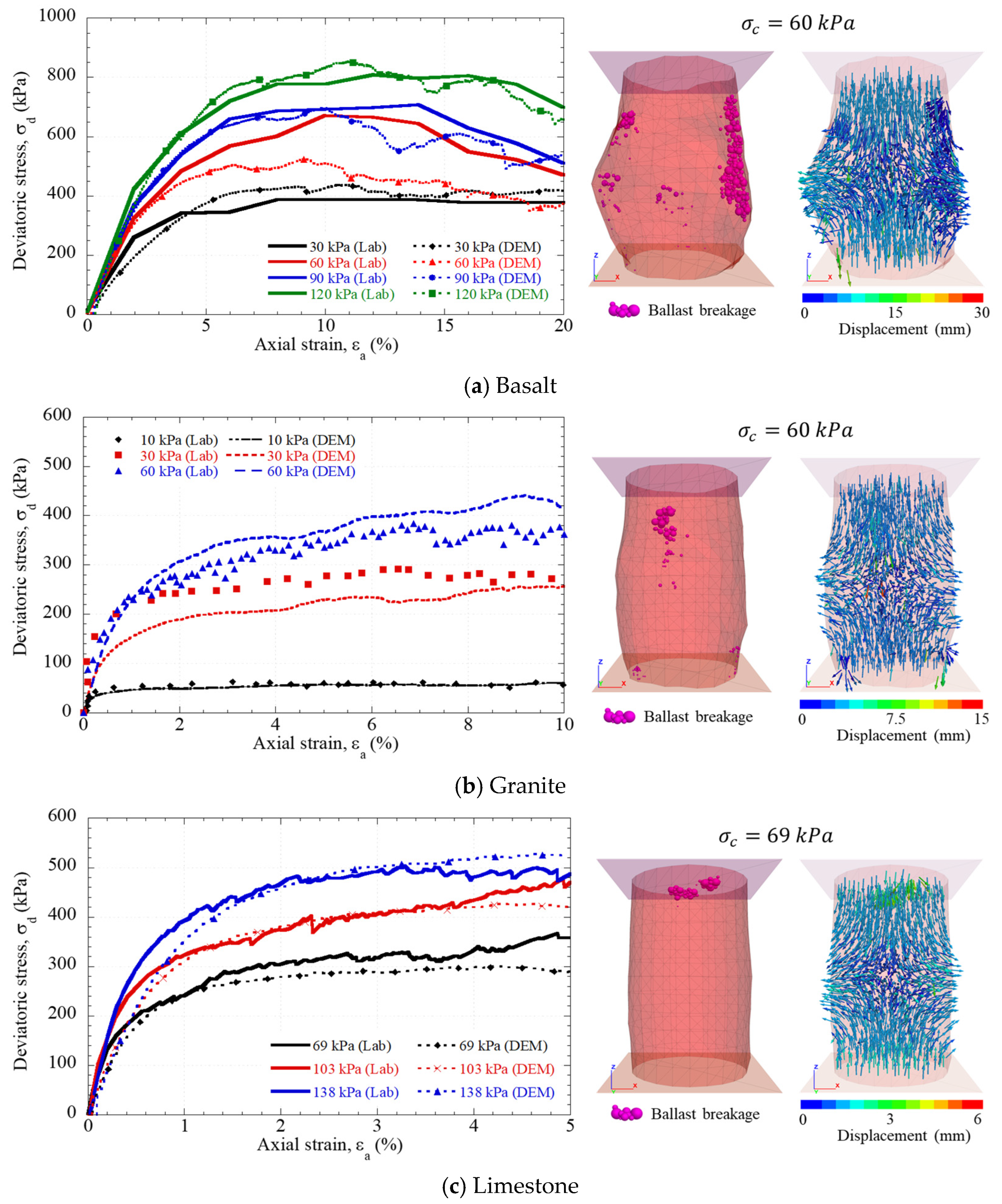
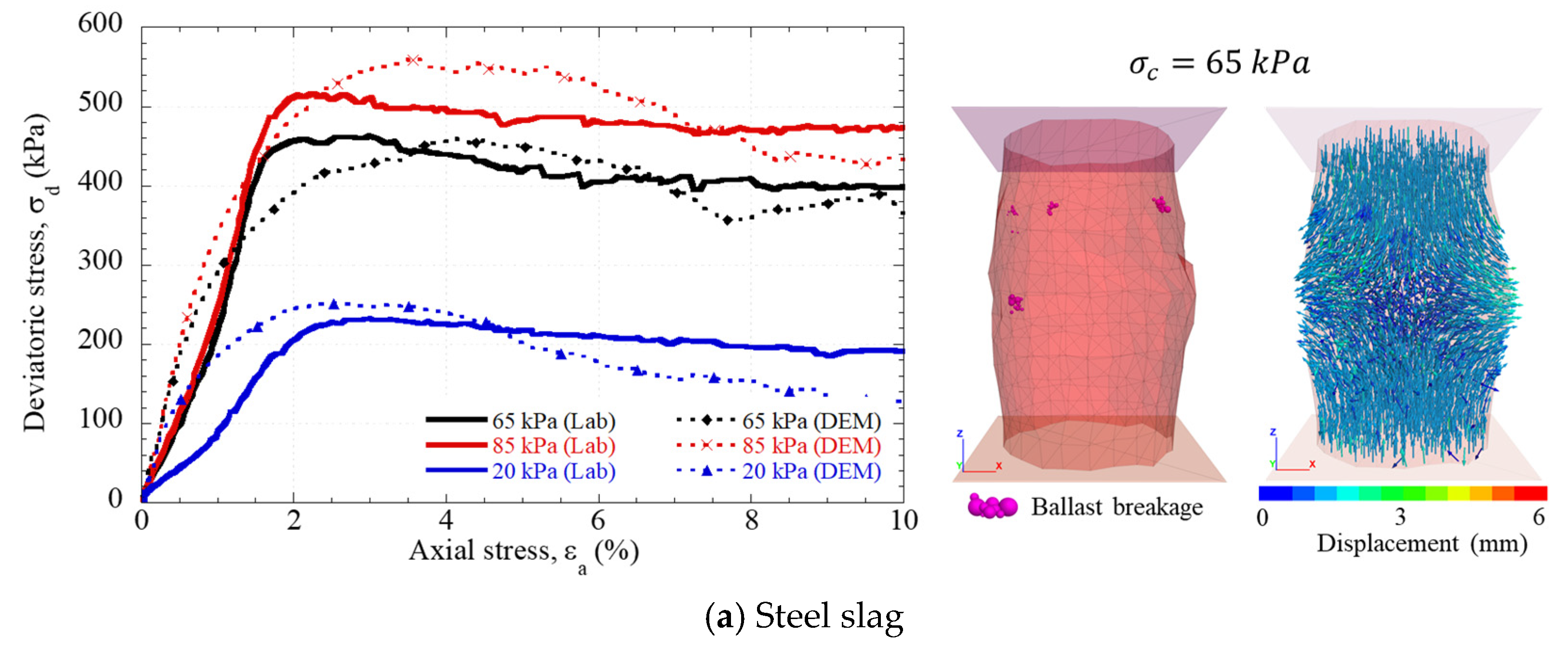
In Figure 8, the calibration results obtained for conventional materials are presented. It is observed that the numerical response satisfactorily reproduces the behavior observed experimentally in large-scale triaxial tests, demonstrating an adequate correspondence between the stress–strain curves for the different levels of confining stress. The specific details of the reference experimental conditions are indicated in Table 3 of Section 2.
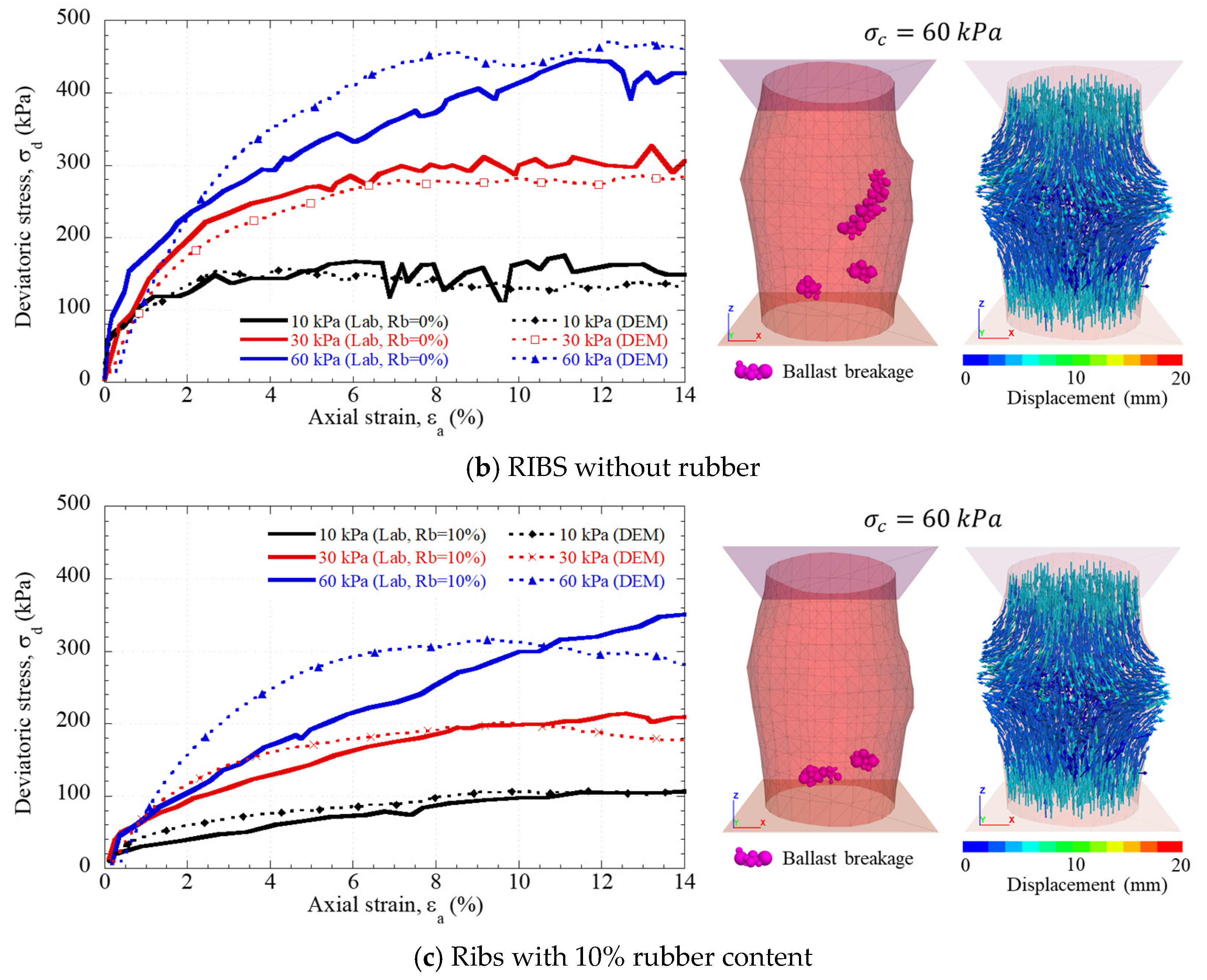
The calibration results for the recycled materials are shown in Figure 9. This difference between computed and experimental data is attributed to the intrinsic properties of these materials, especially rubber, whose high deformability and low stiffness cannot be explicitly represented in PFC, which assumes rigid particles. Nevertheless, the calibration is considered acceptable, as it accurately reproduces the overall response and experimental trends.
Based on the model calibration, it was observed that the normal stiffness (kn) and tangential stiffness (ks) are the parameters that have the most significant influence on the model’s response, as they directly control the initial slope of the stress–strain curve. When these values are high, the material exhibits a more brittle behavior, reaching its peak strength too early. Reducing kn and ks of the rubber particles decreases the initial stiffness and the friction angle. Conversely, while friction mainly controls the maximum strength of the assembly, the rolling resistance determines the shape of the curve in the post-peak stage, defining the transition between the maximum load state and the residual condition.

4.2. Coupled Numerical Model PFC3D—FLAC3D

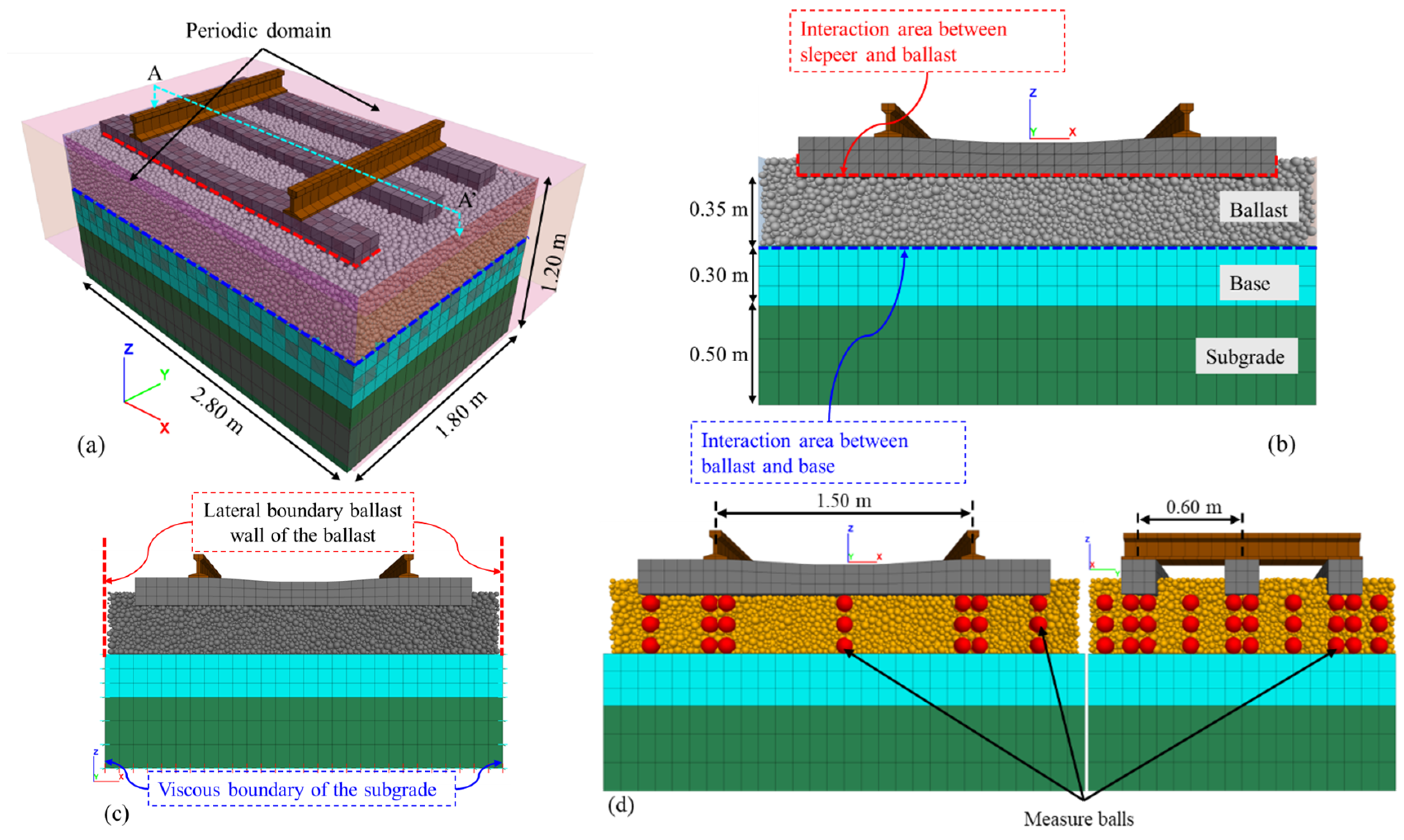
The study evaluated the ballasted track system’s behavior at both macroscopic and microscopic scales, a 3D coupled DEM-FDM model was established, as illustrated in Figure 10a. The FDM modeled the subgrade, base, sleepers, and rail, and the DEM simulated the ballast. Moreover, the interactions between the ballast particles and the base or sleepers were simulated by interface elements generated at the contact area between the discrete and continuous elements.
The track superstructure components (rail and concrete sleeper) are modeled as linear–elastic materials since non-yielding behavior is expected. In the analysis, two different models for the track substructure, elastic and elastoplastic, are considered to study the effect of the material model type on the load and stress path of the railroad. In the case of elastoplastic models, the base is simulated using an elastic-perfect plastic model embracing the Mohr–Coulomb yield criterion, while subgrade is modeled as elastic behavior, the material properties are presented in Table 7.
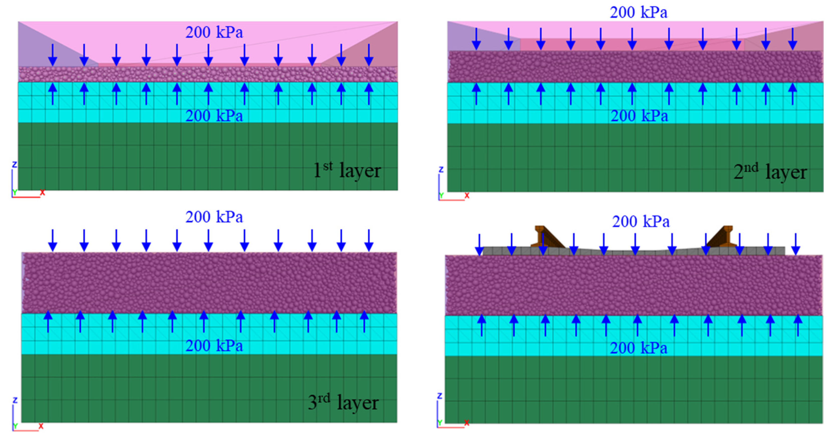
Given the critical role of ballasted track compaction conditions in the simulation, this study employed the multilayer compaction method proposed by several researchers [43,44,62], as illustrated in Figure 11. The compaction procedure was initiated with three ballast layers, with compaction pressures exceeding 200 kPa at each stage. Subsequently, excess particles were removed, and auxiliary surfaces were created. The compaction process was repeated to ensure proper particle densification. Finally, sleepers and rails were positioned on top the ballast layer, after which the auxiliary surfaces were removed.
To characterize the cyclic load transmitted by the bogie, it was considered: (1) the maximum sustained load of 147.15 kN per axle (73.57 kN per wheel), (2) a design speed of 85 km/h, (3) a wheel diameter of 0.914 m, and (4) an Impact Factor, IF (Equation (11)), of 0.48 as recommended by AREMA [63].
I F = 33 V 100 D
where V = speed in mph; D = wheel diameter in inches.
Thus, the cyclic load was applied 100 times with a frequency of 10 Hz, considering a distance between each axle of 2.40 m.
In this initial phase of the research, a 10 Hz frequency load, and limited number of cycles (100) allows to assess the initial evolution of the stiffness, stress distribution, and fracture mechanisms under controlled conditions, without compromising numerical stability or computational cost. The approach aims to identify relative trends among difference materials. However, it is acknowledged that future studies should include a greater number of cycles, as well as coupled fatigue and progressive damage models, to evaluate long-term response and the accumulation of permanent deformations.

5. Results

For each case analyzed, vertical displacements, the vertical stresses, PSD evolution and breakage index were obtained.

5.1. Monotonic Load

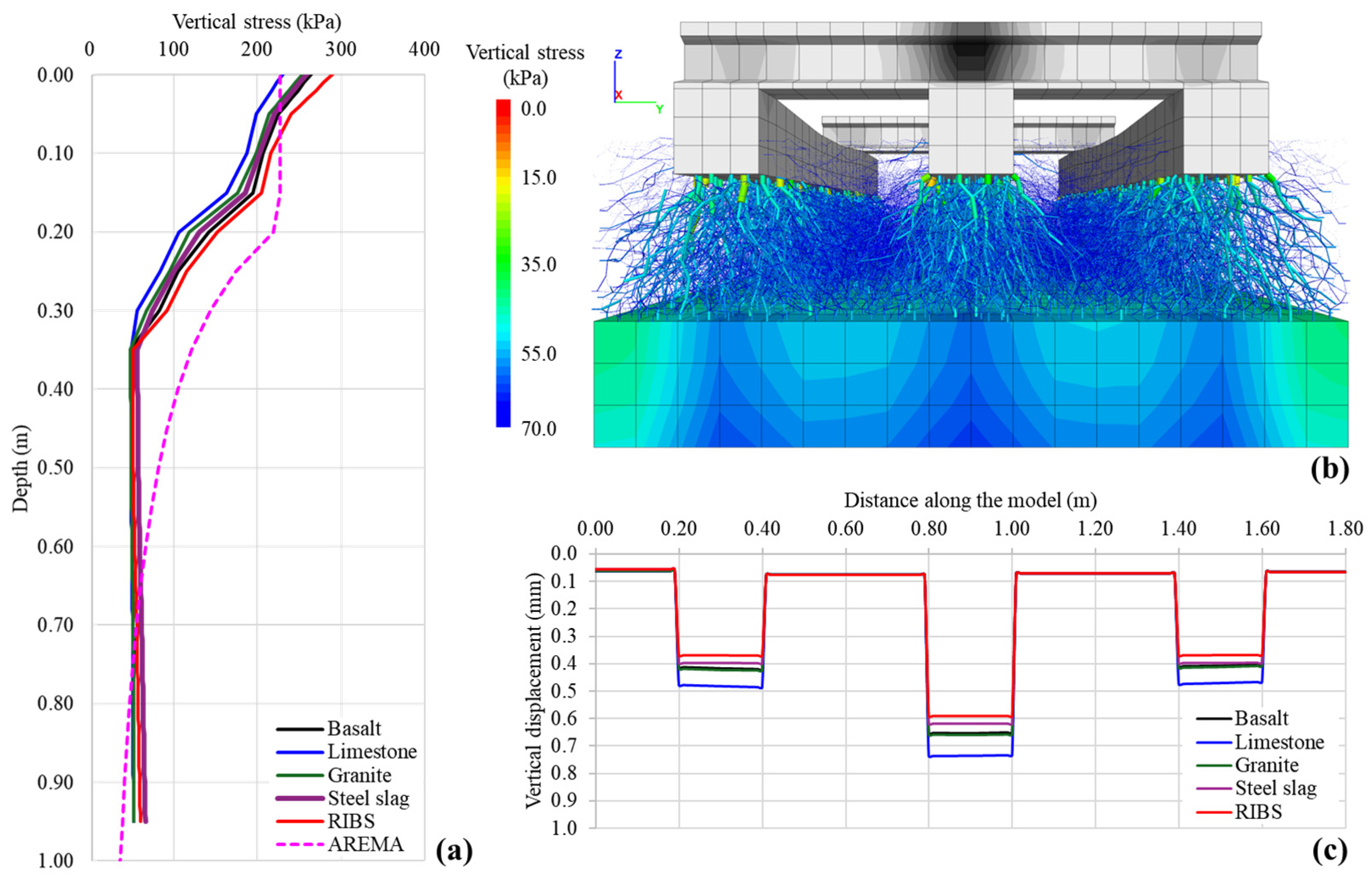
Figure 12 presents the vertical stress distribution versus depth below the loaded sleeper, compared with empirical calculations from AREMA [63]. In 4 of the 5 cases analyzed, the interface stresses at the sleeper-ballast contact exceeded the reference empirical values, reinforcing the need for advanced numerical models in precise track design.
In the present study, it has been observed that both the RIBS material and the steel slag have shown the highest stress concentrations and the lowest vertical displacements, with values below 0.6 mm. However, when considering cyclic loading, these values have increased due to particle rearrangement, breakage, and abrasion. In contrast, the material that exhibited the highest propensity for displacement was limestone, with values of 0.74 mm. Fracture introduces new contact surfaces, influencing stresses and displacements and confirming their dominant role in the overall behavior of the system. However, these results underline the importance of considering particle fracture, even in cases of minimal fracture, as this can affect the evolution of deformation and long-term strength under repeated loading conditions.
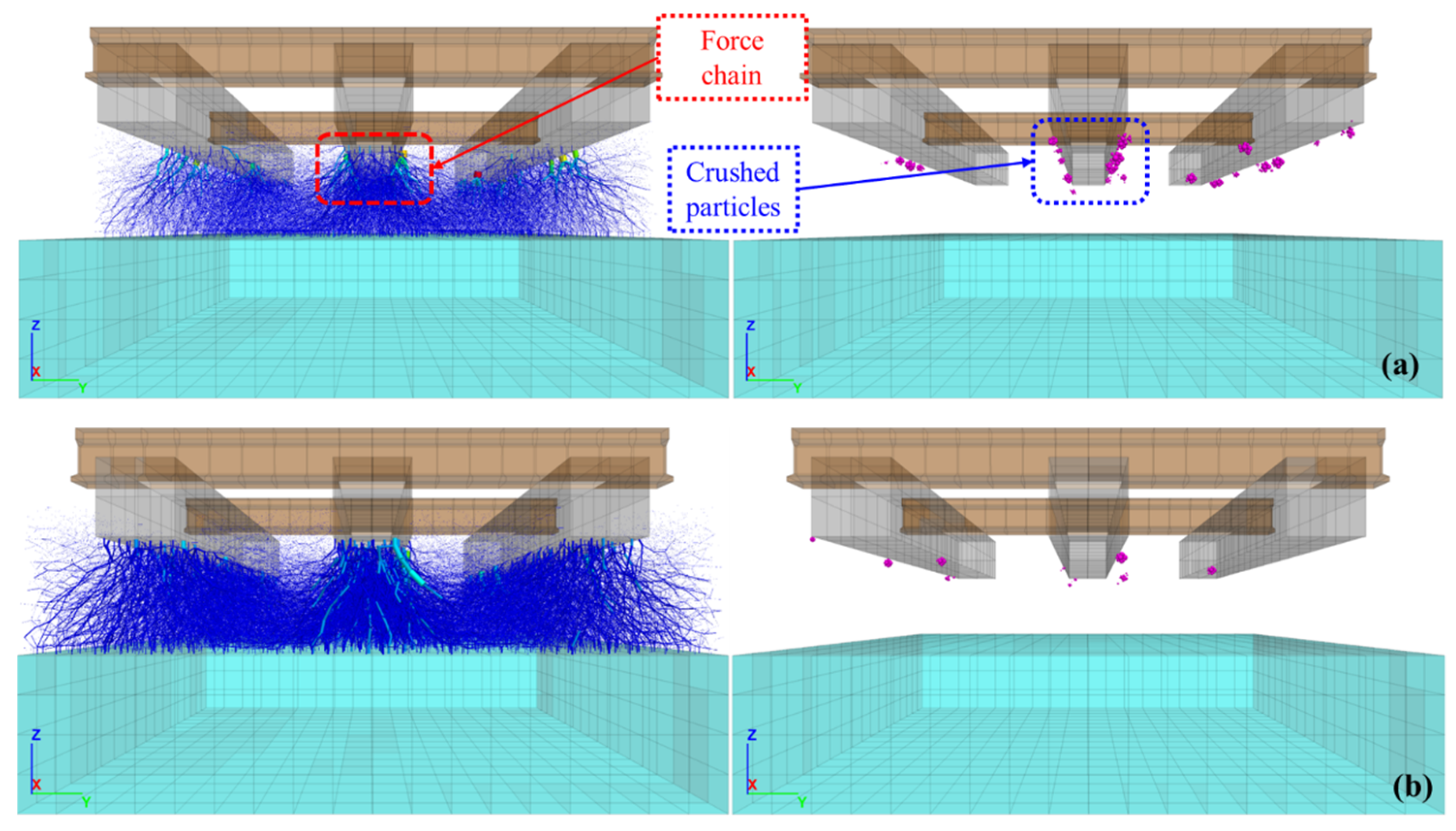
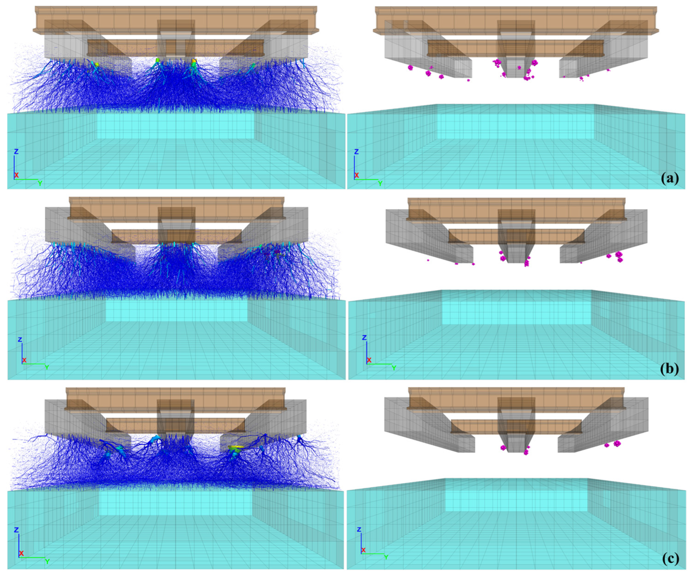
Figure 13 and Figure 14 show the distribution of contact force chains among ballast particles under monotonic load. Each contact force is represented by a cylinder aligned with its direction and with a diameter proportional to its magnitude. The load was applied to both rails on the central sleeper. As shown in the figure, the forces propagate downward into the ballast in a pyramidal pattern, suggesting that the material outside this zone experiences negligible stress. This behavior aligns with findings reported in the literature [64,65]. Additionally, a marked increase in contact forces is observed near the edges of the sleepers, which accounts for the higher particle fracture recorded in these areas.

5.2. Cyclic Loading

The cyclic load was applied to the center sleeper rail in the same way as the monotonic load. This article presents the results corresponding to 100 load cycles applied at a frequency of 10 Hz.
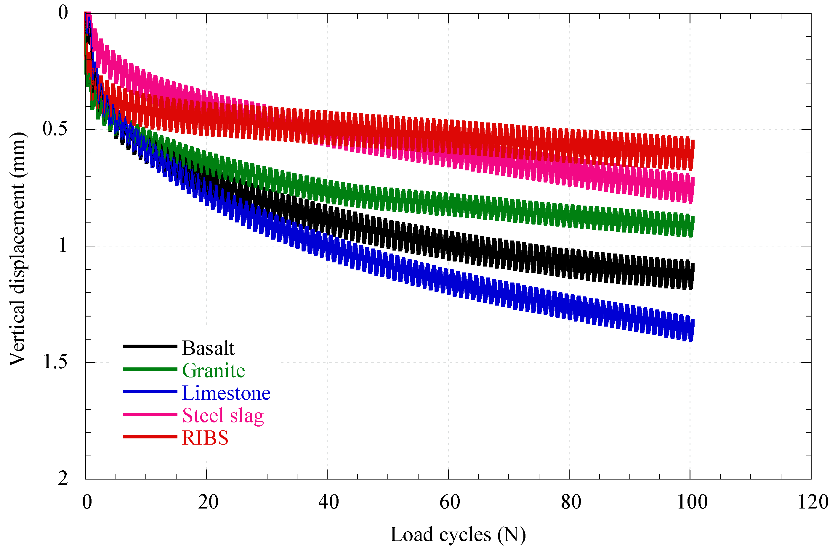
Figure 15 shows how the deformations evolve with the increase in the number of cycles in the sphere located under the central sleeper (shown in Figure 10d). The vertical deformation of the particles at the interface between the sleeper and the ballast is greater during the first load cycle, and subsequently, a linear increase is observed.

5.3. Ballast Breakage

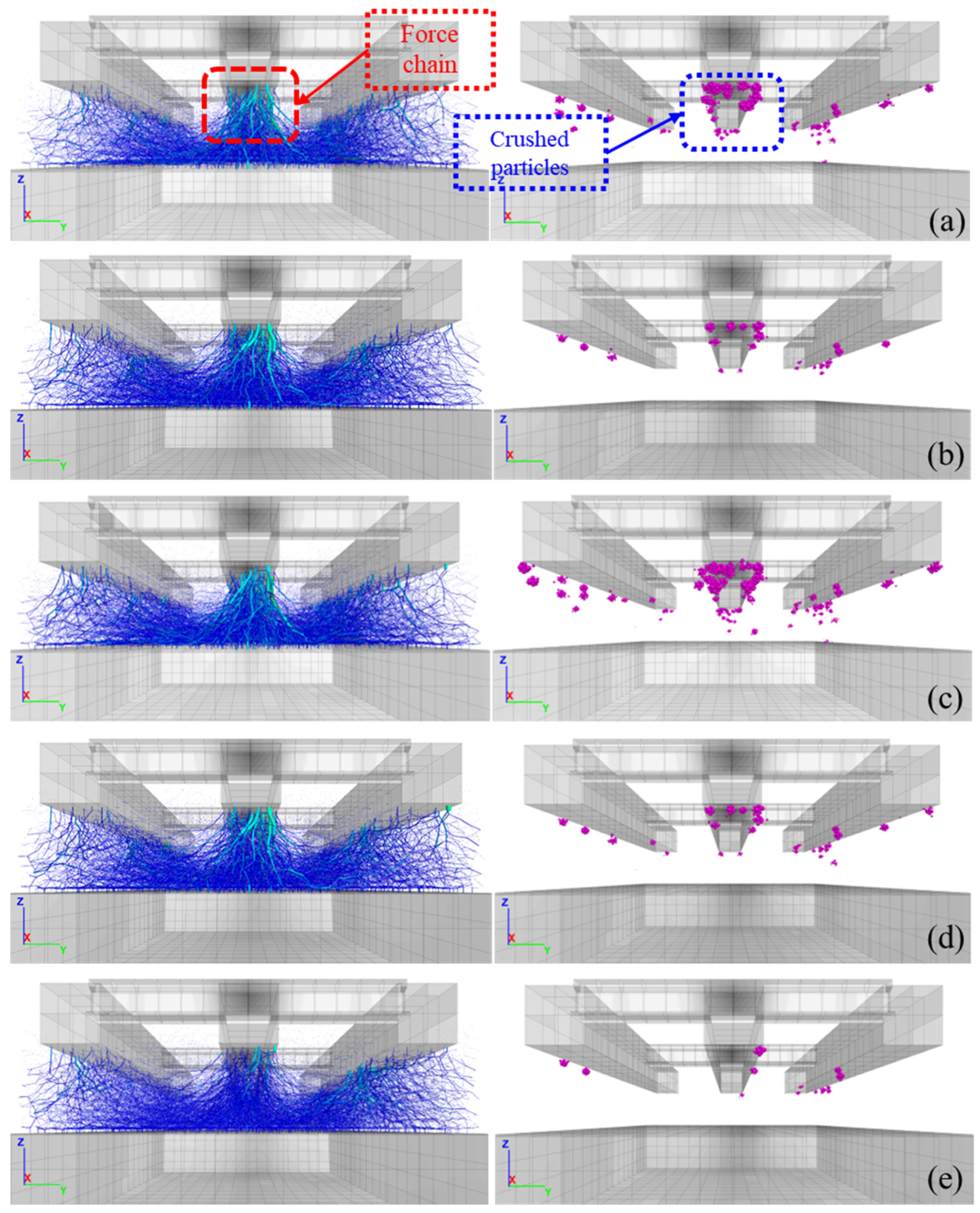
Figure 16 shows that contact forces are significantly greater at the edges of the sleeper, leading to increased particle fracture in these areas. In addition, it can be seen that, after 100 load cycles, particle fracture extends to greater depths and is not limited solely to direct contact with the sleeper, as observed in the analysis under sustained load.
This distribution can be attributed to the generation of smaller particles, which are rearranged by gravity and by the general movement of particles toward the bottom of the layer. This behavior has been corroborated in various field studies and is associated with the phenomenon known as fouling.
Finally, Figure 17 and Figure 18 show the behavior of the breakage indices obtained according to the Indraratna, BBI, and Marsal Bg criteria. It can be seen that particle degradation occurs in particles larger than 25 mm. The ballast breakage index (BBI) decreased by 51.04%, from 0.721 to 0.353, when 10% rubber was added to the RIBS model. Similarly, the breakage index according to Marsal’s criteria (Bg) decreased by 49.43%, from 7.373 to 3.729. These results reflect a significant improvement in the mechanical behavior of the material, supporting its potential practical application in these track support systems.
The current model does not explicitly incorporate environmental effects, such as the presence of water, freeze–thaw cycles, or material aging. This omission responds to the primary objective of the study: to compare the basic mechanical performance of conventional and alternative materials under controlled conditions, before introducing additional environmental variables.
However, there is agreement on the importance of these factors, especially in the case of rubber, whose response can be affected by temperature or surface degradation. Therefore, future research includes the development of a coupled thermo-hydro-mechanical model that allows for analyzing the combined effects of moisture, temperature, and aging on the durability and long-term response of the railway system.

5.4. Economic Implications

The results of this study show that reducing ballast degradation has direct economic effects on the life cycle of the track. In the RIBS mixture (basalt–rubber), a 51% decrease in the BBI index and a 49.4% reduction in the Bg reduces the generation of fines, maintains permeability, and extends the material’s lifespan. This increased durability decreases maintenance frequency, labor and machinery costs, and railway service disruptions, resulting in significant operational savings.
The RIBS system offers the best balance between technical performance and long-term profitability: although its initial cost is higher, the reduction in maintenance offsets the investment. Steel slag is economically viable in regions with local production, while conventional materials have lower initial costs but higher recurring expenses due to degradation.
Additionally, the reuse of waste and the reduced extraction of natural aggregates provide environmental benefits that translate into economic savings and emission reductions. However, the adoption of recycled materials still faces technical, regulatory, and logistical challenges. Therefore, it is recommended to apply life cycle cost analysis (LCCA) tailored to the local context, integrating criteria of cost, performance, and sustainability to guide more efficient and resilient investment decisions.

6. Discussion

One of the main limitations of this study is the simplified geometric modeling of the particles. To optimize calculation time and computational efficiency, a contact model with rotational resistance was used. This model approximately reproduces the effects associated with the angular morphology of the particles.
However, to obtain more realistic simulations, it is recommended to incorporate the actual shape of the particles, whether through agglomerates, polyhedra, or other irregular geometries. Several studies have shown that this representation influences interlocking, shear resistance, and abrasion processes. Adopting this approach would allow for a more detailed analysis of the impact of fines generation and ballast fouling, as well as particle fracture. Finally, applying more advanced contact laws (for example, Newton + Coulomb + Signorini) could improve the simulation of prolonged load cycles and facilitate the study of the long-term behavior of the railway system.
In this context, improving numerical models must be accompanied by a broader understanding of the materials that make up the railway track. The use of recycled materials in the ballast represents an important step toward more sustainable and resilient railway systems. Recent research on steel slag, rubber-ballast mixtures, and tire-derived aggregates has shown improvements in energy absorption and fracture reduction. However, these materials exhibit lower initial stiffness and some uncertainties regarding their durability.
The variability of their properties and the scarcity of long-term tests under real environmental conditions limit their standardization. Therefore, it is essential that predictive models incorporate the effects of temperature, humidity, and aging to more accurately reproduce the behavior of the pathway under actual operational conditions.
Based on this analysis, future research developments should focus on a multiscale understanding of ballast behavior. This should consider both microstructural aspects and environmental and operational effects. The following priority areas are proposed:
  • Analyze the combined effects of temperature, humidity, and chemical aging on recycled ballast.
  • Study the influence of water, saturation, and freeze–thaw cycles through coupled thermo-hydro-mechanical models.
  • Evaluate long-term durability with large-scale cyclic triaxial tests (>106 cycles) and DEM simulations that include multigenerational failure.
  • Conduct life cycle assessments (LCA) and life cycle cost analyses (LCC) to quantify environmental and economic benefits.
  • Develop pilot sections equipped with fiber optic sensors (FBG) and piezometers to validate numerical models and build digital twins that enhance predictive maintenance and performance-based design.
Together, these perspectives drive the transition toward a performance-based, durable, and sustainable railway design framework. This framework should be supported by numerical, experimental, and environmental evidence, and aligned with the principles of circular economy applied to modern railway engineering.

7. Conclusions

The behavior of ballast is closely related to the lithology of the granular material used; therefore, it is essential to analyze a variety of materials in practice to evaluate the structural performance of tracks more comprehensively. There is a broad base of research on ballast materials, including laboratory tests, large-scale trials, and field implementation through pilot tests. However, it is still necessary to deepen the understanding of factors such as the interaction of overall track performance, the effects of extreme environments, advanced multiscale numerical modeling, and rigorous economic-environmental analysis.
This study evaluated three materials conventionally used in track support and two alternatives that, according to bibliographic research, have performed well in different scenarios. The numerical model was calibrated by comparing it with experimental results from large-scale triaxial tests, explicitly considering the particle failure mechanism, and contrasting the stress–strain curves obtained. Once the parameters of each of the materials had been calibrated, they were evaluated under the same confinement stress of 60 kPa, from which the following conclusions were drawn:
  • The breakage indices, Bg, obtained from triaxial tests were low for all materials, indicating good mechanical behavior against fracture. It is important to mention that analysis under cyclic loading is recommended.
  • Particle degradation was mainly concentrated in the <25 mm fractions, consistent with the ballast breakage index (BBI). Minimal differences were observed between curves, resulting in values of less than 5%, indicating good quality ballast.
Subsequently, a coupled DEM-FDM model was performed to simulate the behavior of the materials under sustained and cyclic loads. The following conclusions can be drawn from this analysis:
  • The RIBS system (basalt mixed with rubber) showed the best overall performance, with the lowest fracture rate (0.05%) and reduced vertical displacements (<0.6 mm) under monotonic loading. From a practical perspective, the results question conventional empirical approaches, as in 80% of cases, stresses at the sleeper-ballast interface were higher than expected. In the models subjected to cyclic loading, a significant increase in vertical settlements was observed during the first cycles for the RIBS model. However, this model showed better stabilization of displacements compared to the others.
  • The conventional materials (basalt, granite, and limestone) followed similar displacement trajectories, though with distinct magnitudes of settlement. Limestone showed the most significant final displacement (1.32 mm), followed by basalt (1.08 mm) and granite (0.71 mm). After 100 load cycles, all materials produced vertical stresses exceeding empirical estimates, except for the RIBS model, which reached a maximum stress of 177 kPa and exhibited a more uniform stress distribution.
  • The incorporation of 10% rubber into the basalt ballast significantly improved mechanical performance: the BBI decreased by 51.0% (from 0.721 to 0.353), and the Marsal breakage index (Bg) reduced by 49.4% (from 7.373 to 3.729). These results confirm the effectiveness of rubber intermixing in reducing particle degradation and enhancing ballast resilience.
The results of this research reaffirm the technical potential of using alternative materials and innovative mixtures for application as railway ballast. In particular, the RIBS system, based on a mixture of basalt and rubber, showed superior performance against degradation and deformation, standing out for its low fracture rate, lower vertical displacements under cyclic loading, and a more uniform distribution of stresses. Conventional materials such as basalt, granite, and limestone also showed acceptable performance, although with notable differences in their shear strength and confinement capacity. Steel slag is presented as a viable alternative, provided it meets regulatory requirements, while the breakage indices (Bg and BBI) confirm the good mechanical quality of most of the materials tested. However, the results also reveal limitations in current empirical methods, as in many cases the measured stresses exceed the predicted theoretical values.
The inclusion of granular mixtures with additives, such as rubber, not only improves the structural performance of the ballast but also opens up new opportunities for developing more sustainable and resilient solutions to repeated loads and demanding operating conditions. Further studies are recommended to evaluate the behavior of these materials under extreme environmental conditions and in long-term applications to strengthen their practical implementation in the track support system.

Author Contributions

Conceptualization, J.M.M.; methodology, J.M.M. and N.O.; software, N.O.; validation, J.M.M.; formal analysis, N.O.; investigation, J.M.M. and N.O.; resources, J.M.M.; data curation, N.O.; writing—original draft preparation, N.O.; writing—review and editing, J.M.M. and N.O.; visualization, N.O. All authors have read and agreed to the published version of the manuscript.

Funding

This research received no external funding.

Institutional Review Board Statement

Not applicable.

Informed Consent Statement

Not applicable.

Data Availability Statement

The original contributions presented in this study are included in the article. Further inquiries can be directed to the corresponding author.

Conflicts of Interest

The authors declare no conflicts of interest.

Abbreviations

The following abbreviations are used in this manuscript:
AREMAAmerican Railway Engineering and Maintenance-of-Way Association
BBIBallast Breakage Index
BgBreakage index Marsal
LALos Angeles index
MDMicro-Deval index
DEMDiscrete element method
FDMFinite difference method
RIBSRubber Intermixed ballast Systems

References

  1. Selig, E.; Waters, J. Track Geotechnology and Substructure Management; Thomas Telford: London, UK, 1994. [Google Scholar]
  2. De Paiva, C.E.L.; Pereira, M.L. Sustainability of the Ballasted Track—A Comprehensive Review on Reducing the Use of Mineral Aggregates and the Role of Sub-ballast as a Protective Layer. In Sustainable Solutions for Railways and Transportation Engineering; Springer: Cham, Switzerland, 2018; pp. 67–100. [Google Scholar]
  3. Varandas, J.N.; Paixão, A.; Fortunato, E.; Hölscher, P. A Numerical Study on the Stress Changes in the Ballast Due to Train Passages. Procedia Eng. 2016, 143, 1169–1176. [Google Scholar] [CrossRef]
  4. Liu, H.; Zou, D. Associated generalized plasticity framework for modeling gravelly soils considering particle breakage. J. Eng. Mech. 2013, 139, 606–615. [Google Scholar] [CrossRef]
  5. Gräbe, P.J.; Clayton, C.R. Effects of principal stress rotation on permanent deformation in rail track foundations. J. Geotech. Geoenviron. Eng. 2009, 135, 555–565. [Google Scholar] [CrossRef]
  6. Mayoral Villa, J.M.; Olivera, N.; Tepalcapa, S.; Román, A.; Alcaraz, M. Numerical Assessment of Enhanced Urban-Train Support Systems. In Proceedings of the 10th European Conference on Numerical Methods in Geotechnical Engineering (NUMGE 2023), London, UK, 26–28 June 2023; International Society for Soil Mechanics and Geotechnical Engineering: London, UK, 2023; pp. 2903–2910. [Google Scholar]
  7. Shi, C.; Fan, Z.; Connolly, D.P.; Jing, G.; Markine, V.; Guo, Y. Railway ballast performance: Recent advances in the understanding of geometry, distribution and degradation. Transp. Geotech. 2023, 41, 101042. [Google Scholar] [CrossRef]
  8. Indraratna, B.; Salim, W. Mechanics of Ballasted Rail Tracks: A Geotechnical Perspective; CRC Press: Boca Raton, FL, USA, 2005. [Google Scholar]
  9. Indraratna, B.; Qi, Y.; Tawk, M.; Heitor, A.; Rujikiatkamjorn, C.; Navaratnarajah, S.K. Advances in ground improvement using waste materials for transportation infrastructure. Proc. Inst. Civ. Eng.-Ground Improv. 2022, 175, 3–22. [Google Scholar] [CrossRef]
  10. Indraratna, B.; Nimbalkar, S.; Rujikiatkamjorn, C. Track stabilisation with geosynthetics and geodrains, and performance verification through field monitoring and numerical modelling. Int. J. Railw. Technol. 2012, 1, 195–219. [Google Scholar] [CrossRef]
  11. Chen, C.; McDowell, G.R.; Thom, N.H. Investigating geogrid-reinforced ballast: Experimental pull-out tests and discrete element modelling. Soils Found. 2014, 54, 1–11. [Google Scholar] [CrossRef]
  12. Leshchinsky, B.; Ling, H. Effects of geocell confinement on strength and deformation behavior of gravel. J. Geotech. Geoenviron. Eng. 2013, 139, 340–352. [Google Scholar] [CrossRef]
  13. Indraratna, B.; Qi, Y.; Malisetty, R.S.; Navaratnarajah, S.K.; Mehmood, F.; Tawk, M. Recycled materials in railroad substructure: An energy perspective. Railw. Eng. Sci. 2022, 30, 304–322. [Google Scholar] [CrossRef]
  14. Naeini, M.; Mohammadinia, A.; Arulrajah, A.; Horpibulsuk, S. Recycled glass blends with recycled concrete aggregates in sustainable railway geotechnics. Sustainability 2021, 13, 2463. [Google Scholar] [CrossRef]
  15. Indraratna, B.; Qi, Y.; Ngo, T.; Malisetty, R.; Arachchige, C.K. Innovative and cost-effective rail track construction using recycled rubber. Railw. Eng. Sci. 2024, 33, 327–341. [Google Scholar] [CrossRef]
  16. Alves, R.; Rios, S.; Fortunato, E.; Viana da Fonseca, A.; Guimarães Delgado, B. Mechanical behaviour of steel slag–rubber mixtures: Laboratory assessment. Sustainability 2023, 15, 1563. [Google Scholar] [CrossRef]
  17. Sagar, N.; Hussain, A.; Hussaini, S.K.K. Experimental assessment of shear behavior of crumb rubber intermixed steel slag used as railway subballast. In Proceedings of the 4th Asia-Pacific Conference on Physical Modelling in Geotechnics (ACPMG 2024), Abu Dhabi, United Arab Emirates, 11–13 December 2024; International Society for Soil Mechanics and Geotechnical Engineering: London, UK, 2024. [Google Scholar] [CrossRef]
  18. Kaya, M. A Study on the Stress-Strain Behavior of Railroad Ballast Materials by Use of Parallel Gradation Technique. Ph.D. Thesis, Middle Eastern Technical University, Ankara, Turkey, 2004. [Google Scholar]
  19. Koh, T.; Moon, S.W.; Jung, H.; Jeong, Y.; Pyo, S. A feasibility study on the application of basic oxygen furnace (BOF) steel slag for railway ballast material. Sustainability 2018, 10, 284. [Google Scholar] [CrossRef]
  20. Esmaeili, M.; Nouri, R.; Yousefian, K. Experimental comparison of the lateral resistance of tracks with steel slag ballast and limestone ballast materials. Proc. Inst. Mech. Eng. Part F J. Rail Rapid Transit. 2017, 231, 175–184. [Google Scholar] [CrossRef]
  21. Arachchige, C.M.; Indraratna, B.; Qi, Y.; Vinod, J.S.; Rujikiatkamjorn, C. Deformation and degradation behaviour of Rubber Intermixed Ballast System under cyclic loading. Eng. Geol. 2022, 307, 106786. [Google Scholar] [CrossRef]
  22. Arachchige, C.M.K. Experimental and Numerical Study of Rubber Intermixed Ballast System Subjected to Monotonic and Cyclic Loading; University of Technology: Sydney, Australia, 2022. [Google Scholar]
  23. Bian, X.; Jiang, H.; Cheng, C.; Chen, Y.; Chen, R.; Jiang, J. Full-scale model testing on a ballastless high-speed railway under simulated train moving loads. Soil Dyn. Earthq. Eng. 2014, 66, 368–384. [Google Scholar] [CrossRef]
  24. Indraratna, B.; Hunt, H.; Malisetty, R.S.; Alagesan, S.; Qi, Y.; Rujikiatkamjorn, C. Optimization of inputs for the application of ANN to rail track granular materials. Can. Geotech. J. 2024, 62, 1–22. [Google Scholar] [CrossRef]
  25. Godson, M.D.; Rajesh, B.G.; Kumar, P. Electric arc furnace slag—A prospective alternative for railway sub-ballast layer. Constr. Build. Mater. 2025, 483, 141702. [Google Scholar] [CrossRef]
  26. Nasrollahi, K.; Dijkstra, J.; Nielsen, J.C.O. Towards real-time condition monitoring of a transition zone in a railway structure using fibre Bragg grating sensors. Transp. Geotech. 2024, 44, 101166. [Google Scholar] [CrossRef]
  27. Chen, J.; Liu, Y.; Hu, Q.; Gao, R. Effects of particle size and grading on the breakage of railway ballast: Laboratory testing and numerical modeling. Sustainability 2023, 15, 16363. [Google Scholar] [CrossRef]
  28. Li, W.; Bian, X.; Duan, X.; Tutumluer, E. Full-scale model testing on ballasted high-speed railway: Dynamic responses and accumulated settlements. Transp. Res. Rec. 2018, 2672, 125–135. [Google Scholar] [CrossRef]
  29. Sayeed, M.A.; Shahin, M.A. Design of ballasted railway track foundations using numerical modelling. Part I Development. Can. Geotech. J. 2018, 55, 353–368. [Google Scholar] [CrossRef]
  30. Edwards, J.R.; Gao, Z.; Wolf, H.E.; Dersch, M.S.; Qian, Y. Quantification of concrete railway sleeper bending moments using surface strain gauges. Measurement 2017, 111, 197–207. [Google Scholar] [CrossRef]
  31. Lu, M.; McDowell, G.R. Discrete element modelling of railway ballast under monotonic and cyclic triaxial loading. Géotechnique 2010, 60, 459–467. [Google Scholar] [CrossRef]
  32. Lim, W.L.; McDowell, G.R.; Collop, A.C. The application of Weibull statistics to the strength of railway ballast. Granul. Matter 2004, 6, 229–237. [Google Scholar] [CrossRef]
  33. Li, D.; Selig, E.T. Method for railroad track foundation design. I: Development. J. Geotech. Geoenviron. Eng. 1998, 124, 316–322. [Google Scholar] [CrossRef]
  34. Cundall, P.A.; Strack, O.D.L. A discrete numerical model for granular assemblies. Géotechnique 1979, 29, 47–65. [Google Scholar] [CrossRef]
  35. ASTM C136/C136M-19; Standard Test Method for Sieve Analysis of Fine and Coarse Aggregates. ASTM International: West Conshohocken, PA, USA, 2019.
  36. Indraratna, B.; Ionescu, D.; Christie, H.D. Shear behavior of railway ballast based on large-scale triaxial tests. J. Geotech. Geoenviron. Eng. 1998, 124, 439–449. [Google Scholar] [CrossRef]
  37. Xiao, J.; Zhang, D.; Wei, K.; Luo, Z. Shakedown behaviors of railway ballast under cyclic loading. Constr. Build. Mater. 2017, 155, 1206–1214. [Google Scholar] [CrossRef]
  38. Qian, Y.; Tutumluer, E.; Hashash, Y.M.; Ghaboussi, J. Triaxial testing of new and degraded ballast under dry and wet conditions. Transp. Geotech. 2022, 34, 100744. [Google Scholar] [CrossRef]
  39. Delgado, B.G.; da Fonseca, A.V.; Fortunato, E.; Maia, P. Mechanical behavior of inert steel slag ballast for heavy haul rail track: Laboratory evaluation. Transp. Geotech. 2019, 20, 100243. [Google Scholar] [CrossRef]
  40. Arachchige, C.M.; Indraratna, B.; Qi, Y.; Vinod, J.S.; Rujikiatkamjorn, C. Geotechnical characteristics of a rubber intermixed ballast system. Acta Geotech. 2022, 17, 1847–1858. [Google Scholar] [CrossRef]
  41. Jiang, M.J.; Yu, H.S.; Harris, D. A novel discrete model for granular material incorporating rolling resistance. Comput. Geotech. 2005, 32, 340–357. [Google Scholar] [CrossRef]
  42. Lu, M.M.G.R.; McDowell, G.R. The importance of modelling ballast particle shape in the discrete element method. Granul. Matter 2007, 9, 69–80. [Google Scholar] [CrossRef]
  43. Li, L.; Liu, W.; Ma, M.; Jing, G.; Liu, W. Research on the dynamic behaviour of the railway ballast assembly subject to the low loading condition based on a tridimensional DEM-FDM coupled approach. Constr. Build. Mater. 2019, 218, 135–149. [Google Scholar] [CrossRef]
  44. Xiao, Y.; Shen, Z.; Tan, P.; Hua, W.; Wang, M.; Jitsangiam, P. Evaluating enhancement effect of bottom groove shape on lateral resistance of frictional sleepers in ballasted railway track via hybrid DEM-FDM approach. Constr. Build. Mater. 2024, 436, 136755. [Google Scholar] [CrossRef]
  45. Jiang, M.J.; Shen, Z.F.; Wang, J.F. A novel three-dimensional contact model for granulates incorporating rolling and twisting resistances. Comput. Geotech. 2015, 65, 147–163. [Google Scholar] [CrossRef]
  46. Guo, Y.; Zhao, C.; Markine, V.; Jing, G.; Zhai, W. Calibration for discrete element modelling of railway ballast: A review. Transp. Geotech. 2020, 23, 100341. [Google Scholar] [CrossRef]
  47. Coetzee, C.J. Calibration of the discrete element method. Powder Technol. 2017, 310, 104–142. [Google Scholar] [CrossRef]
  48. Itasca Consulting Group. PFC3D 6.0 Particle Flow Code in Three Dimensions, Theory and Implementation Volume; Itasca Consulting Group: Minneapolis, MN, USA, 2016. [Google Scholar]
  49. Ciantia, M.O.; Arroyo, M.; Calvetti, F.; Gens, A. An approach to enhance efficiency of DEM modelling of soils with crushable grains. Géotechnique 2015, 65, 91–110. [Google Scholar] [CrossRef]
  50. Turcotte, D.L. Fractals and fragmentation. J. Geophys. Res. 1986, 91, 1921–1926. [Google Scholar] [CrossRef]
  51. McDowell, G.R.; Bolton, M.D.; Robertson, D. The fractal crushing of granular materials. J. Mech. Phys. Solids 1996, 44, 2079–2101. [Google Scholar] [CrossRef]
  52. Li, H.Q.; Mcdowell, G.R. Discrete element modelling of under sleeper pads using a box test. Granul. Matter 2018, 20, 26. [Google Scholar] [CrossRef]
  53. Liu, F.; Wu, M.; Wang, H. Effect of particle size ratio and mix ratio on mechanical behavior of rubber-sand mixtures. J. Eng. Geol. 2019, 27, 376–389. [Google Scholar]
  54. Wang, C.; Deng, A.; Taheri, A. Three-dimensional discrete element modeling of direct shear test for granular rubber–sand. Comput. Geotech. 2018, 97, 204–216. [Google Scholar] [CrossRef]
  55. Perez, J.L.; Kwok, C.Y.; Senetakis, K. Micromechanical analyses of the effect of rubber size and content on sand-rubber mixtures at the critical state. Geotext. Geomembr. 2017, 45, 81–97. [Google Scholar] [CrossRef]
  56. Perez, J.L.; Kwok, C.Y.; Senetakis, K. Effect of rubber size on the behaviour of sand-rubber mixtures: A numerical investigation. Comput. Geotech. 2016, 80, 199–214. [Google Scholar] [CrossRef]
  57. Gong, L.; Nie, L.; Xu, Y.; Wang, H.; Zhang, T.; Du, C.; Wang, Y. Discrete element modelling of the mechanical behaviour of a sand-rubber mixture containing large rubber particles. Constr. Build. Mater. 2019, 205, 574–585. [Google Scholar] [CrossRef]
  58. Guo, Y.; Ji, Y.; Zhou, Q.; Markine, V.; Jing, G. Discrete element modelling of rubber-protected ballast performance subjected to direct shear test and cyclic loading. Sustainability 2020, 12, 2836. [Google Scholar] [CrossRef]
  59. Wu, H.; Zhu, L.; Song, W.; Xu, Z.; Xu, F.; Gong, H. Impact performance of ballast by incorporating waste tire-derived aggregates. Constr. Build. Mater. 2021, 288, 122992. [Google Scholar] [CrossRef]
  60. Zhang, F.; Yao, Q.; Wang, H.; Feng, H.; Chang, J.; Lu, L.; Jiang, M. DEM analysis of the cyclic behavior of ballast mixed with crumb rubber. Constr. Build. Mater. 2023, 375, 130975. [Google Scholar] [CrossRef]
  61. Ngo, T.; Indraratna, B.; Coop, M.; Qi, Y. Behaviour of ballast stabilised with recycled rubber mat under impact loading. Géotechnique 2023, 75, 192–212. [Google Scholar] [CrossRef]
  62. Tran, V.D.; Meguid, M.A.; Chouinard, L.E. Discrete element and experimental investigations of the earth pressure distribution on cylindrical shafts. Int. J. Geomech. 2014, 14, 80–91. [Google Scholar] [CrossRef]
  63. AREMA. American Railway Engineering and Maintenance-of-Way Association. Man. Railw. Eng. 2013, 2, 55–57. [Google Scholar]
  64. Mosayebi, S.A.; Zakeri, J.A.; Esmaeili, M. Some aspects of support stiffness effects on dynamic ballasted railway tracks. Period. Polytech. Civ. Eng. 2016, 60, 427–436. [Google Scholar] [CrossRef]
  65. Chen, J.; Vinod, J.S.; Indraratna, B.; Ngo, T.; Liu, Y. DEM study on the dynamic responses of a ballasted track under moving loading. Comput. Geotech. 2023, 153, 105105. [Google Scholar] [CrossRef]
Figure 1. Particle size distribution of materials used in numerical models: Basalt [36], Granite [37], Limestone [38], Steel Slag [39], and RIBS [40].
Applsci 15 11460 g001
Figure 2. Stress–strain curves reported by various researchers for (a) basalt, (b) granite, (c) limestone, (d) steel slag, (e) RIBS with 0% rubber, and (f) RIBS with 10%.
Applsci 15 11460 g002
Figure 3. Linear contact with rolling resistance.
Applsci 15 11460 g003
Figure 4. Schematic diagram of the Linear Contact Model.
Applsci 15 11460 g004
Figure 5. The particle-crushing configuration includes (a) intact grain, (b) sibling disposition, and (c) sibling reorientation, modified from [49].
Applsci 15 11460 g005
Figure 6. Numerical triaxial model: (a) general characteristics and (b) measure balls.
Applsci 15 11460 g006
Figure 7. Specimen for DEM simulation: (a) ballast particles, (b) ball–ball contact, (c) rubber particles, (d) rubber–rubber contact, and (e) ball–rubber contact.
Applsci 15 11460 g007
Figure 8. Comparison of the stress–strain curves from the numerical calibration and experimental results, fractured particles within the triaxial specimens, and displacement vectors at different levels of confining stress in conventional materials.
Applsci 15 11460 g008
Figure 9. Comparison of the stress–strain curves from the numerical calibration and experimental results, fractured particles within the triaxial specimens, and displacement vectors at different levels of confining stress in recycled materials.
Applsci 15 11460 g009aApplsci 15 11460 g009b
Figure 10. Coupled model (a) characteristics, (b) between the continuous domain and the discrete domain, (c) model boundaries, and (d) measuring spheres in the ballast layer.
Applsci 15 11460 g010
Figure 11. Multilayer compacting procedure.
Applsci 15 11460 g011
Figure 12. (a)Vertical stress distribution with depth beneath the central sleeper, (b) stress contours and contact force chains, and (c) y-direction displacement profile.
Applsci 15 11460 g012
Figure 13. Force chain and crushed particles induced from monotonic load for (a) basalt and (b) granite.
Applsci 15 11460 g013
Figure 14. Force chain and crushed particles induced from monotonic load for (a) limestone, (b) steel slag, and (c) RIBS.
Applsci 15 11460 g014
Figure 15. Permanent displacement with the number of load cycles for the materials analyzed.
Applsci 15 11460 g015
Figure 16. Force chain and crushed particles induced from cyclic load for (a) basalt, (b) granite, (c) limestone, (d) steel slag, and (e) RIBS with 10% rubber.
Applsci 15 11460 g016
Figure 17. Marsal’s breakage index, Bg, for all the samples with cyclic load.
Applsci 15 11460 g017
Figure 18. Ballast breakage index, BBI, values all the samples with cyclic load.
Applsci 15 11460 g018
Table 2. Characteristics of materials.
MaterialDensityMD 1LA 2Uniformity
Coefficient, Cu
Coefficient of Curvature, CcDmaxDmin
ρ(%)(%)(-)(-)(mm)(mm)
Basalt [36]2.605.1012.101.480.995313
Granite [37]2.68 1.520.906316
Limestone [38]2.65 1.460.976313
Steel Slag [39]3.2011.0023.001.941.02284
RIBS [40]2.805.2011.702.601.40534.75
1 Micro Deval index test. 2 Los Angeles abrasion index test.
Table 3. Laboratory test data.
MaterialType of TestVoid RatioConfining
Pressure, (kPa)
Axial
Strain, (%)
BasaltTriaxial0.79–0.8430/60/90/12020
GraniteTriaxial-10/30/6010
LimestoneTriaxial-69/103/1385
Steel SlagTriaxial-20/65/8510
RIBSTriaxial0.76–0.8210/30/6020
Table 4. Parameters of the PFC models.
MaterialDensity
(kg/m3)
Normal Stiffness, knShear Stiffness, ksDampingFriction
Coefficient,
μ
Rolling Friction Coefficient,
μr
(N/m)(N/m)---
Basalt26502 × 1062 × 1060.70.40.8
Granite26803 × 1083 × 1080.70.50.6
Limestone26002 × 1072 × 1070.70.50.7
Steel slag32001 × 1091 × 1090.70.40.4
RIBS26505 × 1085 × 1080.70.30.7
Table 7. Material properties for the soils.
GroupConstitutive ModelγcϕEν
(kN/m3)(MPa)(°)(MPa)(-)
SubgradeMohr–Coulomb22.00431430.30
BaseElastic17.6 9,5900.35
SleeperElastic24.0 47,5000.18
RailElastic79.0 210,0000.30
Disclaimer/Publisher’s Note: The statements, opinions and data contained in all publications are solely those of the individual author(s) and contributor(s) and not of MDPI and/or the editor(s). MDPI and/or the editor(s) disclaim responsibility for any injury to people or property resulting from any ideas, methods, instructions or products referred to in the content.