Abstract
Studying the luminescent properties and the light amplification capabilities are fundamental investigations for newly synthesized organic compounds intended to act as chromophores. These studies are conducted for compounds in the form of solutions, solids, and also molecules stabilized with the aid of polymers. One of the methods used to study amplification is the generation of amplified spontaneous emission (ASE) using stripe-shaped light beam excitation. This process can lead to the generation of ASE, but also, with the coexistence of microcrystals and scatterers, to the generation of laser action with random feedback, known as random lasing (RL). However, when the degree of light scattering is too high, it can lead to the inhibition of laser emission. Therefore, as an alternative in studying amplification properties, we developed a protocol that allows the investigation of laser action generation using rapidly prototyped polymer waveguides with an embedded dye. The setup used was based on Direct Laser Writing (DLW), which enables the controlled fabrication of multimode optical waveguides. We demonstrated that the use of this technique will allow for the study of the performance of dyes from strictly structured resonators, enabling measurements of gain and lasing threshold. This allowed us to lower the lasing thresholds while maintaining the directionality of emission.
1. Introduction
The escalating demand for compact, energy-efficient optical systems necessitates a shift toward integrated photonics [1,2]. Integrated optical circuits, fundamentally enabled by the optical waveguide, offer superior performance and size reduction compared to traditional bulk methods [1]. Polymer-integrated photonics is a leading platform addressing the exponential need for high-speed interconnects and versatile sensing, due to polymers’ inherent advantages: low-cost fabrication, easy modification, and excellent optical properties [3,4]. These attributes are crucial for high-throughput applications like Co-Packaged Optics (CPO), where polymer optical waveguides are promising for short-to-medium reach interconnects, offering flexibility and seamless microelectronic integration [5,6].
Fluorinated UV-curable polymers are vital materials for high-performance passive devices [4]. They can be engineered to exhibit tunable low refractive indices and minimal propagation losses at telecommunication wavelengths, serving as both core and cladding layers [4]. To ensure the stability required for passive operation, these materials are often formulated as nanocomposites by incorporating low refractive index inorganic nanoparticles to achieve low thermo-optic coefficients [4]. This tunability and manufacturing flexibility make them optimal for CPO [6]. Recent confirmation of the high long-term reliability and power handling of single-mode polymer waveguides validates their deployment with External Laser Sources (ELS) [6].
The development of complex integrated structures, such as microring resonators [7], relies on advanced fabrication. Femtosecond Direct Laser Writing (FsDLW) is a highly versatile, mask-less micro- and nanofabrication technology [8,9,10] that allows for the rapid creation of arbitrary optical waveguides in various polymers via two-photon or multiphoton absorption [1]. Specifically, Two-Photon Polymerization (TPP) uses ultrafast pulses to induce highly localized refractive index changes [11,12], enabling the fabrication of complex, 3D photonic structures directly on polymer chips, including single-mode waveguides with losses as low as 1.27 dB/cm [13]. While DLW provides geometric freedom, the high-throughput Roll-to-Plate (R2P) nanoimprinting technique offers an alternative for large-scale manufacturing, achieving losses of 0.19 dB/cm [14].
The high resolution of TPP is uniquely suited for fabricating demanding passive components like low-loss channel waveguides, complex resonant structures, and tapers [7,11,15]. Its compatibility with numerous polymer systems, including SU-8 [16], and its ability to construct micro- and nanostructures directly onto optical fiber tips [16] underscore its versatility. DLW is also essential for active photonic devices, enabling components like erbium-doped polymer micro-waveguide amplifiers for on-chip gain in the telecommunication band [17,18]. For integrated splitters and couplers, DLW allows for the precise engineering of the laser’s focal field [19,20]. Research on perfluorinated acrylate-based materials also suggests avenues for reconfigurable optical elements via Laser Transmission Induced Transparency (LTIT) [21]. DLW is also leveraged to integrate coupling and readout elements onto planar polymer waveguides, creating compact integrated sensor systems [22].
2. Materials and Methods
Fluorescent dye-doped waveguides were fabricated using the Direct Laser Writing (DLW) technique on a custom setup built based on a 3D CNC router with a spatial resolution of 10 m. For this purpose, a contaminant-free substrate made of glass, polycarbonate (PC), or 100 m thick PET foil was coated using the Doctor Blade technique with a mixture of a commercial resin (Anycubic) containing 2-[(1-oxo-2-propen-1-yl)oxy]ethyl ester (40–50%), 2,2’-(ethylenedioxy)diethyl diacrylate (20–30%), propylidynetrimethanol (10–25%), 2-[[2,2-bis[[(1-oxoallyl)oxy]methyl]butoxy]methyl]-2-ethyl-1,3-propanediyl diacrylate (5–20%), and ethyl phenyl(2,4,6-trimethylbenzoyl)phosphinate (1–3%). The layer thickness was adjustable, with the default layer thickness set to 10 μm (Figure 1a). A constant blade speed of 50 mm/s was used for uniform layer coating and better stability of translation. The content of Rhodamine 6G dye in the mixture was 1% (w/w) (Tables S1 and S2).

Figure 1.
(a) Scheme of substrate coating with a thin resin layer: BL–blade, SM–sample, H–adjustable layer height. (b) Scheme of the Direct Laser Writing technique. Structures were precisely fabricated in the XY plane using a 445 nm laser and a ×20 MO with an NA of 0.4. (c) Example images of the fabricated structures without dye doping. (d) Scheme of the setup for laser action generation: a 532 nm wavelength light beam was used for excitation, where /2–half-wave plate, PL–polarizer, CL–cylindrical lens, WG–waveguides, EM–emission observation direction. (e) Dependence of the width of waveguides fabricated by the DLW method as a function of writing speed.
The coated substrates were then transferred to the DLW system, where the waveguide writing process took place. The system allows for the modeling and subsequent fabrication of arbitrary 2D structures designed in CAD software (FreeCad 0.21). In our research, we limited ourselves to one-dimensional structures to simplify the setup. A 445 nm diode laser with a nominal optical power of 200 mW was used for writing. The writing beam was prepared by attenuating it a hundredfold and then expanding it to match the aperture of a ×20 magnification microscope objective (Figure 1b). The numerical aperture (NA) of the objective, NA = 0.4, theoretically allows the beam to be focused down to a 1 μm spot size for the selected writing wavelength. The writing of the planar waveguides was restricted to linear structures, which was relevant for the excitation of the structures. The choice of the DLW technique was dictated by the sufficient amount of active material forming the waveguide to achieve population inversion and laser emission, despite the significantly lower resolution of the structures compared to TPP. The structures created in this way have a greater chance of generating effective lasing. After fabrication, the remaining unpolymerized monomer was washed out using ethanol and isopropanol.
The prepared structures, which varied in fabrication parameters, were used in the light amplification process to generate laser action via optical excitation. For this purpose, an optical setup based on a nanosecond Nd:YAG laser was employed, featuring a pulse duration of 7 ns, a wavelength of 532 nm, and a repetition rate of 10 Hz. The beam power was controlled using a combination of a half-wave plate and a polarizer, maintaining a vertical beam polarization (Figure 1d).
The prepared beam was then focused using a cylindrical lens. The beam width was controlled, allowing for a modified excitation length area (or variable excitation stripe length (VSL)) to be obtained [23]. The laser action emission was collected into an optical fiber and analyzed using an Andor Shamrock spectrometer with a spectral resolution below 0.1 nm. The collected emission spectra were subjected to spectral analysis following the previously established protocol [24,25].
3. Results and Discussion
3.1. Fabrication Conditions
When fabricating polymer structures on the prepared surfaces, the key process was the preparation of a monomer layer with a defined thickness. The omission of this step led to an uneven layer thickness in the form of a meniscus, which was permanently fixed by the light beam during polymerization. The single-photon polymerization process, carried out in the beam-illuminated area, led to the polymerization of the material at the point of illumination, but also nearby, due to the diffusion of the activated photoinitiator. Structures fabricated in this way exhibited insufficient adhesion to the glass surface, resulting in the curling of the polymerized waveguides. This process can be evaluated by checking the waveguiding conditions for waveguides placed on glass. A higher refractive index of the substrate compared to the polymerized structure resulted in a lack of waveguiding in such a structure. In contrast, low adhesion and the lack of surface adherence lead to clear light waveguiding, as demonstrated for a focused HeNe laser beam at the input of the waveguide structure (Figure 2c). For structures prepared in this way, the loss coefficient for light propagation in waveguides was estimated. To achieve this, the change in the intensity of scattered light was determined as a function of propagation length, resulting in a loss value of 1.55 dB/cm. These high losses are related to the fabrication of the structures directly on the substrate.

Figure 2.
(a) Image of an optical waveguide doped with Rhodamine 6G (Rh6G), fabricated on a 100 m thick PET foil. (b) Image of waveguides containing Rh6G on a PC substrate, additionally excited using a UV diode. (c) Waveguiding process in an undoped waveguide using a HeNe laser on a glass substrate, showing the waveguiding effect. (d) Image of the point excitation of a dye-doped waveguide, showing consecutive reflections inside the structure due to total internal reflection.
As a result of coating the doped resin onto the support layer, a uniform thickness distribution was obtained, which led to stable, consistent waveguide thickness (Figure 1c). Controlling the laser beam parameters and writing speed led to a modification of the waveguide thickness, which was inversely proportional to the speed, as shown in Figure 1e. For this purpose, a series of polymerized waveguides was fabricated using different laser beam translation speeds. The evaluation of the thickness change as a function of speed was conducted on resin without the Rhodamine 6G dye dopant, solely for the purpose of system calibration. When the speed was varied, the fabricated waveguides maintained a constant width, which changed only as a function of speed. Adjusting the vertical position (height) of the microscope objective also allowed for the control of the structure’s thickness. However, the commercial resin used, which contains cross-linking agents, resulted in structures that were wider than theoretically calculated for the light beam. Selecting an appropriate formulation will significantly improve the entire process, leading to the production of repeatable, thinner fibers.
Taking into account the limitations resulting from waveguiding in the structure on both glass and polymer substrates made of PC and PET, the utilization of various substrates is shown in Figure 2. Using PET foil allowed for the fabrication of flexible waveguides. To counteract the leakage of light into the substrate during emission generation, a series of structures for laser action generation were fabricated on commercial PC substrates dyed black (Figure 2b). The low energy of the writing beam does not affect the substrate material but only leads to the polymerization of the illuminated area. In this way, the emission generated from these structures cannot “leak” into the substrate because it is absorbed. Only directional emission can be observed, which was confirmed in the experiment. The generated laser action was characterized by directional emission, which was visible as a bright streak located on the extension of the illuminated waveguide upon excitation using a stripe-like beam after the cylindrical lens. Excitation with the nanosecond laser beam did not lead to the destruction of the waveguide structure or to changes in the substrate itself. The beam energies utilized were too low to cause decomposition or destruction.
Microscopic imaging allowed us to investigate the morphology of the rapid prototyping waveguides. For this purpose, microscopy was used in transmission mode, as well as a fluorescence microscope with point excitation from a picosecond laser beam with a wavelength of 532 nm, a pulse duration of 600 ps, and a repetition rate of 100 kHz. The doped waveguides exhibited fluorescence upon optical excitation, which allowed for a more detailed visualization of the fabricated structures, as shown in Figure 2d. Due to the use of a CNC router built on stepper motors, the backlash effect was observable in the fabricated structures (Figure S1). During the laser beam translation, there was a moment where the translation speed was not linear, causing structural non-uniformity. The optical waveguides fabricated in this manner possess a regular but wavy character along the optical fiber. This is presented in Figure 2d, where curvature changes on the order of 150 m were observed along the structure’s length. Observing this effect was possible only with point excitation, and the emitted light followed the structure’s micro-curvature, leading to clear waveguiding with a reflection angle of approximately 60°. Upon stripe-like beam excitation, this effect was not visible due to the excessive light intensity. Introducing this type of structuring can have a twofold effect on the generated laser emission. On one hand, the waveguide character is disrupted, hindering the propagation of the longitudinal mode. On the other hand, it may have a positive effect due to the additional lensing present in the structure and decoupling of light. Thus, rapid waveguides can be used for exciting Whispering Gallery Mode (WGM) resonators in close proximity to the optical fiber [25]. Furthermore, light recirculation due to the enforced additional curvature enables efficient waveguiding, even with a larger structure width, thanks to the additional focusing.
3.2. Lasing Threshold
To investigate the system performance, a series of waveguides with variable lengths between 2 and 6 mm were fabricated. The optical excitation system was set up so that the width of the excitation stripe fully covered the polymerized area. A series of emission spectra were collected as a function of the pumping beam’s energy density to find the characteristic inflection point corresponding to the threshold value for laser action generation. The change in the integrated intensity under the emission spectrum as a function of energy density exhibits a characteristic shape, with a well-defined inflection point corresponding to the lasing threshold [26], as shown for a 3 mm long waveguide (Figure 3f). The collected spectra differed between series originating from different waveguides. However, the fabrication conditions for all structures were constant. Depending on the fiber length, the central position of the emission band shifted (Figure 3a–e). With increasing length, a shift was observed toward longer light wavelengths. The aggregation phenomenon of Rhodamine 6G dye into non-fluorescent H-aggregates and red-shifted J-aggregates and higher-order aggregates is known [27]. However, in the situation considered, the preparation conditions were identical, so the difference is only related to the scattering phenomenon, which decreases with increasing wavelength. Consequently, emission at a longer wavelength had a greater chance of propagating along the waveguide. No formation of microscopic aggregates or crystallites was observed in the area of the polymerized structure. Compared to thin polymer films, this is an advantage of our rapid prototyped waveguides, as the formation of aggregates in the layer is a rather common phenomenon in films, and these aggregates make a significant contribution to the form of laser light emission from such a structure [28].

Figure 3.
(a–e) Series of normalized laser emission spectra for waveguides with lengths ranging from 2 to 6 mm upon excitation with a beam energy density of mJ/cm2. (f) Example dependence of the integrated intensity as a function of energy density for a 3 mm long waveguide. (g) Dependence of the lasing threshold for waveguides of various lengths. (h) Fourier transform of the emission spectrum collected for waveguides of various lengths, with the dominant harmonic highlighted in gray, corresponding to an optical path length of approximately 25 m.
The recorded emission spectra exhibit a distinct modal character with a predominant single laser mode. This is related to a specific longitudinal mode propagating within the waveguide. Furthermore, Fourier transform analysis highlights that the recorded spectra show a significant contribution to the emission from a resonator with an optical path length of approximately 25 m, which may be associated with a perpendicular mode decoupled in the propagation direction (Figure 3h). Conversely, the distinct characteristic of separated modes is not visible, indicating a negligible contribution of this harmonic to the total emission spectrum. The contribution of this harmonic decreases with the waveguide length and is best visible for the shortest 2 mm structure. The emission character changes, and with increasing length, there is an increase in the contribution carried by the longitudinal mode, while the other resonances become limited. The longitudinal mode cannot be easily analyzed using the spectrum FFT due to its contribution to the zero harmonic. The previously described focusing effect at the waveguide curvatures may make a significant contribution to the light decoupling process and the formation of optical resonators at the surface irregularities. This significantly impacts the system performance, leading to a reduction in effective gain.
Lasing threshold measurements were performed as a function of the excitation length, restricted only to the range possible within the experimental setup. This relates the length of the excited area to the laser emission threshold. The threshold values decrease with increasing excitation length, and above 4 mm, reach a constant value of 0.25 mJ/cm2, showing a characteristic exponential dependence as a function of length (Figure 3g). The system stabilizes above 4 mm, and the emission properties remain constant. The designated lasing threshold error decreased as the excited area increased. This indicates the stability of the observed emission. For a longer excitation area, this results in a more defined inflection point. The light distribution for a larger area is more uniform, which limits the diversity of the lasing threshold. The process of changing the emission wavelength relative to successive measured samples is natural and results from the aggregation of Rhodamine 6G into J-aggregate dye and higher-order aggregates. This process may be caused by mixing the dye and resin. Excitation of the waveguide-formed structure is efficient to such an extent that a comparison with analogous systems utilizing planar waveguides shows a nearly order-of-magnitude lower laser emission threshold for systems doped with Rhodamine 6G [26].
3.3. Planar and Linear Waveguide
The proposed fabrication of rapid waveguides holds particular significance compared to planar waveguides used as a thin dye-doped polymer layer in a host–guest system. Limited control over layers fabricated by the drop-casting method leads to the formation of crystallites, surface non-uniformities, and a lack of thickness control, which is only regulated by defining the solution volume [29]. While Doctor Blade provides thickness control, the aggregation problem remains significant. In situ polymerization of waveguides provides a much greater control over fabrication parameters and allows for the addition of functionalities in an entirely custom manner by building the light propagation paths within the system.
Compared to generating laser action using just a cylindrical lens for planar waveguides, significant light recirculation losses are caused by the diffusion of light out of the structure in a direction perpendicular to the propagation direction, facilitated by scattering elements present in the layer. Although the excited area exhibits light amplification properties, the efficiency of such a process is limited. The application of the presented rapid preparation protocol for structure fabrication significantly improves the system’s performance, showing a nearly order-of-magnitude lower laser threshold [26]. Controlling the width of the fabricated structures by selecting the appropriate beam focus enables light recirculation and efficiency enhancement.
In the case of thin polymer layers forming planar waveguides, significant light losses result from leaking modes into the substrate upon which the layer is deposited. The thickness of the substrate glass slide serving as support for the soft matter is also critical. If the light emission from a planar waveguide excited by a stripe-like beam is scattered due to diffusion, the probability of emitting light with good coherence and in the direction of the illuminated area is lower. However, the substrate glass slide allows for light propagation due to waveguiding. The amount of light will depend on the thickness of the slide, which affects the angle of the observed emission, particularly the differentiation of emitters. Consequently, this leads to the separation of laser modes in the laser action emission spectrum. For a thicker slide, more emitted light reaches the detector, so the emission is a superposition of multiple signals, whereas for a thinner one, the signal consists only of a limited number of emitters. This is evident when analyzing the number of laser modes in the lasing spectrum. Examples of this effect can be seen in Figure 4a. A thin polymer layer containing Rhodamine 6G at a concentration of 1% (w/w) in a PMMA layer, excited on the same experimental setup with a stripe-like beam, shows a completely different laser emission signal when a 100 m thick slide versus a 1 mm thick slide is used as the support. The total observed emission is a superposition of the signal resulting from waveguiding in the polymer layer during the amplification process, as well as light that has leaked into the support glass layer. By increasing the thickness of the substrate slide, the total amount of light waveguided in the support increases, leading to the overlapping of the lasing signal. Not only is the light excited along the entire length of the illuminated area observed, but also light from every point within the illumination area. In comparison, a thin 100 m support limits this effect due to the smaller amount of light that can directly travel towards the detector via shorter edge of the support glass. This results in a clear difference in the Fourier transform of the emitted signal (Figure 4b). For the thin layer, consecutive harmonics are separated and belong only to a single resonator, which is recognizable by the equal distance between them. However, for the thick substrate glass layer, resonances overlap, and the FFT presents multiple harmonics from resonators present during excitation. The signal superposition with a thick support hinders spectral analysis of the laser modes, and even FFT analysis does not allow for an unambiguous correlation of the emission with a specific optical resonator.

Figure 4.
(a) Normalized laser emission spectra for a Rhodamine 6G-doped PMMA layer on a support with a thickness of 100 m and 1 mm, along with (b) the corresponding Fourier transforms of the emission spectra. (c) Dependence of the intensity change observed due to waveguiding through the support as the excitation area length increases, including the emission model. (d) Laser emission spectrum for an organic waveguide with visible laser modes, corresponding to (e) a resonance size of approximately 25 m, according to the position of the first harmonic in the FFT. (f) Directional emission of laser action from the waveguide.
The analysis of light “leakage” through the substrate for emission from thin films can be simplified and characterized as the sum of emission originating from the interface between the glass of thickness d and the dye-doped polymer layer. Ignoring light excited in the layer itself, as well as reabsorbed or waveguided light, we can assume that emission reaches the detector from every point at an angle directly to the edge of the support, according to Figure 4c. It is as if every excited point were a spherical wave source. A portion of the light radiated through the glass layer is visible at an angle relative to the outer edge of the area. Disregarding waveguiding and multiple reflections within the glass, the emission from each point has a value of . The angular intensity increment can then be described as
Thus, the total emission radiated directly through the glass from a single point is the integral from 0 to , yielding . The angle depends on the length of the excited area x, which is . The waveguided intensity component resulting from direct radiation from the interface between the layers is the integral over the length of the stripe considering the above equations:
where L is the length of the excitation area. The result after analytical integration is equal to
Assuming an , the total emitted light from the excitation zone is . However, the amount of light due to waveguiding in the glass changes as a function of the substrate glass thickness, as presented in Figure 4c. This constitutes a significant contribution to the observed laser emission on the glass support. It must be remembered, though, that the effect is amplified by total internal reflection, which further enhances the observed phenomenon.
When exciting the waveguide structures fabricated as rapid prototypes, it is possible to excite specific optical modes. The fundamental mode of the excited waveguide should be the longitudinal mode, leading to laser action generation at a specific wavelength, as occurred in the lasing threshold measurements described above. However, light may also be emitted where the optical resonance can be formed around the perimeter or across the width of a given waveguide. The formation of such emitters was also observed during our research. As shown in Figure 4d, well-defined laser modes are visible in the laser emission plot. The width of the main modes is significant, around 1 nm, which suggests a not sufficiently high Q-factor for this resonant system, or it may result from the non-uniform structure and thickness fluctuation in the given waveguide. This, consequently, could lead to the superposition of the lasing signal from coexisting resonators in the illuminated area. The calculated Fourier transform value (Figure 4e) clearly indicates 23 m as the harmonic responsible for laser action generation. We previously showed that curvature fluctuation and total internal reflection were observed at these curves. The Fourier transform analysis of the emission spectrum reveals a strictly defined harmonic responsible for emission under these resonance conditions. There is a possibility to tune the transverse laser modes by changing the thickness of the waveguides in a strictly controlled manner during fabrication, which additionally allows for the design of resonant systems according to specific requirements.
3.4. WGM Type Optical Resnator
The formation of waveguides represents a step toward the rapid prototyping of structures for light amplification and beam parameter modulation. This should be treated as a platform for light delivery. Beyond laser action generation, the application of such structures can involve the delivery and collection of light from photonic structures fabricated with sub-micrometer precision. For this purpose, we used the Two-Photon Polymerization technique described elsewhere [30,31]. We used an optical resonator in the form of a cylinder as a model, fabricated from a mixture of PETA and PEG-DA, with the photoinitiator being 3,5-Tris(2-(9-ethylcarbazol-3)ethylene)benzene (TECEB). A cylindrical structure with a diameter of 30 m and a height of 20 m (Figure 5b inset) was built using the TPP system based on a 532 nm picosecond laser and a ×60 microscope objective with an NA of 0.85. The cylinder thus formed was saturated with Rh6G dye from an ethanol solution to excite emission. However, the low amount of dye was insufficient to achieve amplification, as indicated by Figure 5a. The resulting signal constitutes only light interference on the given structure with insufficient gain.
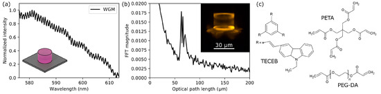
Figure 5.
(a) Fluorescence emission spectrum for a cylindrical WGM resonator showing interference, and (b) the corresponding Fourier transform of the signal. The inset contains an image of the structure excited under a fluorescence microscope. (c) Chemical structures of PETA, PEG-DA, and TECEB photoinitiator monomers.
Combining the functionality of rapid prototyped organic waveguides with other structures that can build fully functional photonic systems is essential for the development of micro-optical technologies. Furthermore, creating fast prototype structures for testing optical solutions that are cost-effective to manufacture provides opportunities for rapid development in the field. Currently used fabrication techniques, based on mask-based photolithography, are expensive and do not allow for quick modifications. The continually evolving polymer technologies and manufacturing of polymer materials significantly lower the barrier to entry for research into photonic technologies.
4. Conclusions
Replacing planar thin polymer films with organic waveguides has the potential to achieve better-defined laser action, as we demonstrated based on the system doped with Rhodamine 6G dye. The use of rapid waveguides also provides the opportunity for precise investigation of gain and lasing thresholds as a function of length, serving as an alternative to the Variable Stripe Length (VSL) method. Of particular note is the capability to shape waveguide structures to obtain well-defined laser emission with strictly specified resonances, which are directly related to the waveguide structure. The fabricated precise structures can be applied in the illumination of micro-photonic circuits, for example, those built directly adjacent to the waveguide using Two-Photon Polymerization methods, as well as for the delivery and collection of light to and from optical microresonators.
Supplementary Materials
The following supporting information can be downloaded at: https://www.mdpi.com/article/10.3390/app152111459/s1. References [32,33] are cited in the supplementary materials.
Author Contributions
Conceptualization, K.C.; methodology, M.W.; investigation, M.W.; writing preparation, K.C.; supervision, K.C. All authors have read and agreed to the published version of the manuscript.
Funding
This work was supported by the statutory funding of Chemistry Department, Wroclaw University of Science and Technology.
Data Availability Statement
The raw data supporting the conclusions of this article will be made available by the authors on request.
Conflicts of Interest
The authors declare no conflicts of interest.
References
- Li, J.; Cao, C.; Qiu, Y.; Kuang, C.; Liu, X. Optical waveguides fabricated via femtosecond direct laser writing: Processes, materials, and devices. Adv. Mater. Technol. 2023, 8, 2300620. [Google Scholar] [CrossRef]
- Annadhasan, M.; Basak, S.; Chandrasekhar, N.; Chandrasekar, R. Next-generation organic photonics: The emergence of flexible crystal optical waveguides. Adv. Opt. Mater. 2020, 8, 2000959. [Google Scholar] [CrossRef]
- Pitwon, R.; Wang, K.; Yamauchi, A.; Ishigure, T.; Schröder, H.; Neitz, M.; Singh, M. Competitive evaluation of planar embedded glass and polymer waveguides in data center environments. Appl. Sci. 2017, 7, 940. [Google Scholar] [CrossRef]
- Goldenberg, L.M.; Köhler, M.; Dreyer, C. Fluorinated polymers for photonics—From optical waveguides to polymer-clad glass optical fibers. Appl. Sci. 2025, 15, 1790. [Google Scholar] [CrossRef]
- Manvelova, T.; Tarasov, S.; Ivanov, N. Polymer optoelectronic bus for high-speed data transmission systems. J. Phys. Conf. Ser. 2019, 1400, 066051. [Google Scholar] [CrossRef]
- Suda, S.; Noriki, A.; Kuwatsuka, H.; Nakamura, F.; Atsumi, Y.; Kurosu, T.; Murao, T.; Amano, T. High-Power Stability and Reliability of Polymer Optical Waveguide for Co-Packaged Optics. J. Light. Technol. 2025, 43, 4903–4912. [Google Scholar] [CrossRef]
- La, T.L.; Bui, B.N.; Nguyen, T.T.N.; Pham, T.L.; Tran, Q.T.; Tong, Q.C.; Mikulich, A.; Nguyen, T.P.; Nguyen, T.T.T.; Lai, N.D. Design and Realization of Polymeric Waveguide/Microring Structures for Telecommunication Domain. Micromachines 2023, 14, 1068. [Google Scholar] [CrossRef]
- Zhang, Y.; Yu, B.; Zhang, Z.; Duan, X.; Wang, J. Developments of waveguide lasers by femtosecond laser direct–writing technology. Photonics 2024, 11, 803. [Google Scholar] [CrossRef]
- Li, L.; Kong, W.; Chen, F. Femtosecond laser-inscribed optical waveguides in dielectric crystals: A concise review and recent advances. Adv. Photonics 2022, 4, 024002. [Google Scholar] [CrossRef]
- Roth, G.L.; Kefer, S.; Hessler, S.; Esen, C.; Hellmann, R. Polymer photonic crystal waveguides generated by femtosecond laser. Laser Photonics Rev. 2021, 15, 2100215. [Google Scholar] [CrossRef]
- Baghdasaryan, T.; Vanmol, K.; Thienpont, H.; Berghmans, F.; Geernaert, T.; Van Erps, J. Design and two-photon direct laser writing of low-loss waveguides, tapers and S-bends. J. Phys. Photonics 2021, 3, 045001. [Google Scholar] [CrossRef]
- Muševič, I.; Vellaichamy, M.; Jagodič, U.; Pišljar, J.; Jelen, A.; Nych, A.; Škarabot, M.; Zaplotnik, J.; Ravnik, M. Direct laser-written waveguides for integrated liquid crystal micro-photonics. In Proceedings of the Liquid Crystals Optics and Photonic Devices, Strasbourg, France, 7–11 April 2024; SPIE: Bellingham, WA, USA, 2024; Volume 13016, pp. 93–101. [Google Scholar]
- Ng, K.; Chong, W.; Lim, C.; Ahmad, H. Single-mode SU-8 waveguide fabricated using ultrafast direct laser writing. Optik 2022, 270, 170068. [Google Scholar] [CrossRef]
- Prajzler, V.; Chlupaty, V.; Kulha, P.; Neruda, M.; Kopp, S.; Mühlberger, M. Optical polymer waveguides fabricated by roll-to-plate nanoimprinting technique. Nanomaterials 2021, 11, 724. [Google Scholar] [CrossRef] [PubMed]
- Panusa, G.; Pu, Y.; Wang, J.; Moser, C.; Psaltis, D. Fabrication of sub-micron polymer waveguides through two-photon polymerization in polydimethylsiloxane. Polymers 2020, 12, 2485. [Google Scholar] [CrossRef]
- Xiong, C.; Liao, C.; Li, Z.; Yang, K.; Zhu, M.; Zhao, Y.; Wang, Y. Optical fiber integrated functional micro-/nanostructure induced by two-photon polymerization. Front. Mater. 2020, 7, 586496. [Google Scholar] [CrossRef]
- Arrue, J.; Jiménez, F.; Ayesta, I.; Asuncion Illarramendi, M.; Zubia, J. Polymer-optical-fiber lasers and amplifiers doped with organic dyes. Polymers 2011, 3, 1162–1180. [Google Scholar] [CrossRef]
- Gao, H.; Li, H.; Chen, G.F.; Xing, P.; Tan, M.C.; Tan, D.T. 3D printed and spiral lithographically patterned erbium-doped polymer micro-waveguide amplifiers. Sci. Rep. 2021, 11, 21292. [Google Scholar] [CrossRef]
- Wu, P.; Yang, S.; Ren, Y.; Liu, H. Beam splitters fabricated by nonlinear focusing of femtosecond laser writing in pure YAG crystal. Front. Phys. 2021, 9, 719757. [Google Scholar] [CrossRef]
- Sheng, Y.; Wen, X.; Jia, B.; Gan, Z. Direct laser writing on halide perovskites: From mechanisms to applications. Light Adv. Manuf. 2024, 4, 95–116. [Google Scholar] [CrossRef]
- Liu, J.; Wang, C.; Dang, Z.; Chu, Y.; Zhang, Z. Thermally resettable laser transmission induced transparency in polymer waveguides at 635 nm. Opt. Express 2022, 30, 17529–17540. [Google Scholar] [CrossRef]
- Alamán, J.; López-Valdeolivas, M.; Alicante, R.; Sánchez-Somolinos, C. Optical planar waveguide sensor with integrated digitally-printed light coupling-in and readout elements. Sensors 2019, 19, 2856. [Google Scholar] [CrossRef]
- Cerdán, L. Variable Stripe Length method: Influence of stripe length choice on measured optical gain. Opt. Lett. 2017, 42, 5258–5261. [Google Scholar] [CrossRef] [PubMed]
- Cyprych, K.; Karpinski, P.; Sznitko, L.; Miniewicz, A.; Mysliwiec, J. Fourier transform analysis of multi-cavity random laser spectra: Applicability and limits. Opt. Mater. 2022, 128, 112322. [Google Scholar] [CrossRef]
- Ryglowski, L.; Cyprych, K.; Mysliwiec, J. The differentiation procedure between amplified spontaneous emission and lasing phenomena. Opt. Commun. 2022, 510, 127939. [Google Scholar] [CrossRef]
- Sznitko, L.; Szukalski, A.; Cyprych, K.; Karpinski, P.; Miniewicz, A.; Mysliwiec, J. Surface roughness induced random lasing in bio-polymeric dye doped film. Chem. Phys. Lett. 2013, 576, 31–34. [Google Scholar] [CrossRef]
- Janeczko, M.; Cyprych, K.; Kozbial, M.; Mysliwiec, J. Analysis of organic luminescent dye aggregation forms embedded in cyclodextrins via random lasing. Org. Electron. 2020, 85, 105888. [Google Scholar] [CrossRef]
- Cyprych, K.; Janeczko, M.; Rau, I.; Kajzar, F.; Mysliwiec, J. Collagen network as the scaffold for spontaneously distributed optical resonators. Org. Electron. 2016, 39, 100–104. [Google Scholar] [CrossRef]
- Bravo-Sánchez, A.I.; Castillo-Mixcóatl, J.; Moreno-Acosta, M.Á.; Sosa-Ramos, O.; Rodríguez-Torres, M.; Beltrán-Pérez, G.; Altuzar, V.; Mendoza-Barrera, C.; Muñoz-Aguirre, S. Automation of the drop-casting deposition method for polymeric sensing films over a quartz crystal microbalance. Discov. Appl. Sci. 2025, 7, 676. [Google Scholar] [CrossRef]
- Durko-Maciag, M.; Ulrich, G.; Massue, J.; Mysliwiec, J.; Cyprych, K. Two is better than one: ESIPT dyes as photoinitiators in two-photon polymerization. Eur. Polym. J. 2023, 195, 112235. [Google Scholar] [CrossRef]
- Piskorz, K.; Starzak, K.; Noworyta, M.; Cyprych, K.; Bartkowski, K.; Badri, Z.; Dhiman, S.; Foroutan-Nejad, C.; Mysliwiec, J.; Lindner, M.; et al. Strain-Activated Photo-Dehalogenation Unlocks Low-Energy One and Two-Photon 3D Microfabrication. Adv. Funct. Mater. 2025; early view. [Google Scholar]
- Standard Resin SDS; UFI: 44JA-57CW-7Q50-TPYU; Shenzhen Anycubic Technology Co., Ltd.: Shenzhen, China, 2024; Available online: https://store.anycubic.com/pages/resin-user-manual (accessed on 20 October 2025).
- User Guide for Standard Resin; Shenzhen Anycubic Technology Co., Ltd.: Shenzhen, China, 2022; Available online: https://store.anycubic.com/pages/resin-user-manual (accessed on 20 October 2025).


Disclaimer/Publisher’s Note: The statements, opinions and data contained in all publications are solely those of the individual author(s) and contributor(s) and not of MDPI and/or the editor(s). MDPI and/or the editor(s) disclaim responsibility for any injury to people or property resulting from any ideas, methods, instructions or products referred to in the content. |
© 2025 by the authors. Licensee MDPI, Basel, Switzerland. This article is an open access article distributed under the terms and conditions of the Creative Commons Attribution (CC BY) license (https://creativecommons.org/licenses/by/4.0/).