Article

Enhancement of Mechanical Properties and Hydrogen Embrittlement Resistance of Laser-Directed Energy Deposition-Fabricated 316L Stainless Steel by Laser Shock Peening

Smart Forming Process Group, Korea Institute of Industrial Technology (KITECH), Ulsan 44776, Republic of Korea
Appl. Sci. 2025, 15(17), 9481; https://doi.org/10.3390/app15179481
Submission received: 25 July 2025 / Revised: 10 August 2025 / Accepted: 27 August 2025 / Published: 29 August 2025
(This article belongs to the Special Issue The Applications of Laser-Based Manufacturing for Material Science)

Abstract

316L stainless steel offers attractive characteristics for hydrogen applications, including low hydrogen diffusivity and high hydrogen solubility. However, its use is limited by relatively low strength and resistance to hydrogen embrittlement (HE) under prolonged hydrogen exposure. Laser-directed energy deposition (L-DED) can not only increase the strength of 316L, but also induce significant tensile residual stresses that promote HE. In this study, 316L stainless steel samples produced by L-DED were post-processed by laser shock peening (LSP) to release the tensile residual stresses and refine the near-surface microstructure. LSP-treated samples showed refined grains, higher hardness, and the introduction of compressive residual stress, which led to improved tensile performance in hydrogen. Notably, after seven passes of LSP, the HE index (reduction in elongation due to hydrogen) was 12.5%, compared with 36.1% for the unpeened material. These results demonstrate that LSP is an effective approach to simultaneously increase strength and significantly improve HE resistance in additively manufactured 316L stainless steel.

1. Introduction

With hydrogen gaining attention as a next-generation clean energy source, research on structural materials for high-capacity and long-term hydrogen storage has accelerated in recent years [1,2,3,4,5,6]. However, when common carbon steels are used, hydrogen can readily infiltrate the metal, causing hydrogen embrittlement (HE) that deteriorates ductility and toughness, ultimately leading to safety hazards and higher maintenance costs [7,8,9]. Austenitic stainless steels, which are relatively less susceptible to HE, have therefore attracted increasing interest in hydrogen infrastructure applications [10]. Among them, 316L stainless steel offers notable advantages, including a stable face-centered cubic (FCC) structure at room temperature, high corrosion resistance, and low hydrogen diffusivity [11,12]. Nevertheless, prolonged exposure to hydrogen can still degrade its mechanical performance, and its relatively low strength remains a limitation to broader adoption in demanding hydrogen service environments [9,13].
To overcome these limitations, metal additive manufacturing (AM) techniques have been explored to enhance both strength and HE resistance in 316L stainless steel [14,15]. For example, Claeys et al. reported that powder bed fusion (PBF)-fabricated 316L exhibited approximately 12% lower HE susceptibility compared with conventionally manufactured 316L [14]. Hong et al. further showed that the cellular dislocation structure formed during PBF fabrication can suppress deformation-induced martensitic transformation, thereby reducing HE susceptibility [15]. Furthermore, alloys fabricated by AM can achieve higher strength than cast counterparts due to rapid solidification rates [16,17]. The hierarchical microstructure of AM 316L, characterized by high dislocation density within grains, provides greater HE resistance than conventionally processed 316L [18].
However, AM processes inevitably introduce significant tensile residual stresses due to steep thermal gradients and cyclic reheating during fabrication [19]. Such tensile stresses can lead to part distortion and reduced fatigue strength and, in particular, facilitate crack initiation and propagation [20], allowing hydrogen to accumulate rapidly at defects and reduce HE resistance [21]. To overcome these issues, various surface strengthening and residual stress modification methods have been applied to AM materials. For instance, Leuders et al. combined hot isostatic pressing (HIP) and shot peening to reduce tensile residual stress in PBF-produced Ti–6Al–4V [22]. AlMangour and Yang demonstrated that shot peening of laser-directed energy deposition (L-DED)-fabricated 17-4 PH stainless steel improved surface roughness, hardness, yield strength, and wear resistance and introduced compressive residual stresses [23]. Similarly, combined post-treatments, such as the hybrid application of shot peening and laser shock peening (LSP), have been shown to enhance fatigue life and surface integrity in AM Ni-based superalloys [24] and cemented carbides [25]. Surface deformation hardening methods like shot peening induce plastic deformation at the material surface and generate compressive residual stresses, effectively impeding hydrogen ingress and suppressing the absorption, dispersion, and accumulation of hydrogen at crack sites, thereby mitigating hydrogen-assisted crack growth [26,27].
Various post-processing techniques have been investigated to enhance the hydrogen embrittlement (HE) resistance of 316L stainless steel, each with its own advantages and limitations. Heat treatment and hot isostatic pressing (HIP) are effective in relieving residual stresses and reducing porosity, thereby enhancing HE resistance [28,29]. Mechanical surface strengthening methods such as shot peening and ultrasonic impact treatment increase dislocation density and grain boundary area in the surface layer, thereby interrupting hydrogen transport and reducing the hydrogen concentration [30,31]. Nevertheless, these techniques typically provide a hardened depth of only a few hundred micrometers, and achieving uniform surface properties can be challenging [32]. Surface coating approaches, including diamond-like carbon (DLC), can effectively suppress hydrogen permeation, but coating defects may lead to localized hydrogen accumulation and premature cracking [33]. In comparison, LSP generates high-magnitude compressive residual stresses to depths of several millimeters and refines the near-surface grain structure through severe plastic deformation. These changes increase the density of hydrogen trap sites, thereby reducing hydrogen diffusivity and delaying crack initiation and growth [34].
Among various techniques, LSP has recently gained attention as a laser-based surface hardening process capable of generating much-deeper and higher-magnitude compressive residual stresses than conventional shot peening [35,36]. LSP employs a high-intensity, short-duration laser pulse (strain rate on the order of 106 s−1) to induce sever plastic deformation at the surface, leading to grain refinement and increased dislocation density. In the field of additive manufacturing (AM), LSP has shown significant benefits in modulating residual stress and enhancing fatigue performance in various alloys including aluminum alloys [37]. However, despite these advances in AM materials, there has been limited research on applying LSP to 316L stainless steel fabricated by L-DED, particularly concerning hydrogen embrittlement resistance. Therefore, in this study, multiple LSP treatments were applied to L-DED 316L stainless steel, followed by comprehensive microstructural and mechanical characterization, as well as HE resistance evaluation via electrochemical hydrogen pre-charging and mechanical testing.

2. Materials and Methods

A commercial 316L stainless steel powder (Koswire) produced by gas atomization was used in this study. The chemical composition of the powder is shown in Table 1. Figure 1 shows an SEM image of the morphology of the 316L stainless steel powder and the particle size distribution (measured by LA-960, HORIBA). The powder particles are predominantly spherical and have a size distribution in the range of 65.4–130 μm.
The L-DED build was carried out using a commercial machine (Lasertec 65 3D Hybrid, DMG Mori) equipped with a 1070 nm Ytterbium fiber laser. Figure 2 shows a photograph of the actual deposition process and a schematic diagram illustrating the scanning strategy and dimensions of the deposited block. A zigzag scanning strategy was applied, in which each layer was deposited with a bidirectional path, followed by a return to the original starting point for the next layer. The build parameters employed in the L-DED process are listed in Table 2. Argon gas was used as the carrier gas for powder feeding and as the shielding gas to prevent oxidation of the as-built blocks. The substrate was a 316L stainless steel block (220 × 150 × 35 mm3) that was face-milled to improve surface flatness and finish. Before the build, the substrate surface was cleaned with ethanol to remove any dust or contaminants. All L-DED experiments were conducted at a controlled ambient temperature of 21 °C and a relative humidity below 60%.
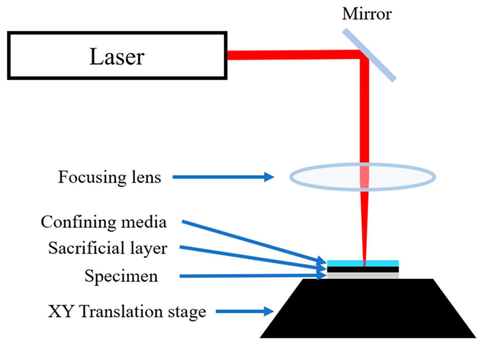
Tensile test specimens were prepared from the blocks built by L-DED for mechanical testing. As shown in Figure 3, the dog-bone tensile specimens were fabricated from the rectangular L-DED 316L blocks by wire electrical discharge machining, with the tensile axis oriented perpendicular to the build direction. Figure 4 shows the experimental setup of laser shock peening, which was applied to the top surface of each tensile specimen, as displayed in Figure 5b. This description clarifies the specimen position and orientation, which is important for interpreting the results given the anisotropy of L-DED 316L stainless steel.
The LSP experiments were performed using an Nd:YAG laser system (LPY787G-10, Litron Lasers) with a wavelength of 1064 nm. Water was used as the confining layer and black tape as the absorbing layer during peening. The LSP process parameters are given in Table 3. The laser-induced shock pressure was calculated by the following equation [38,39]:
P = 0.01 α 2 α + 3 1 / 2 Z 1 / 2 I 0 1 / 2
Here, α is the fraction of absorbed energy (typically ~0.1 in nanosecond laser ablation [38]), I 0 is the laser irradiance in GW/cm2, and Z is the acoustic impedance in kg·m−2 s−1. The impedance Z is calculated by 2 Z = 1 Z 1 + 1 Z 2 , where Z 1 and Z 2 are the impedance of the confining medium (1.49 × 10⁶ kg·m−2 s−1 for water [40]) and the target (4.66 × 10⁶ kg·m−2 s−1 for 316L stainless steel [41]), respectively.
Figure 5 shows (a) a photograph of the actual tensile test specimen subjected to laser shock peening (LSP) and (b) a schematic illustration of the LSP-processed region and the zigzag scanning strategy applied. The laser impact path was kept constant, while the number of LSP passes was varied to investigate the effect of repeated impacts. The LSP treatment was applied to the gauge section of the tensile specimens using the process parameters listed in Table 3. LSP was performed with three different repetition counts: 3, 5, and 7 passes. These conditions were designated as LSP 3, LSP 5, and LSP 7, respectively. For comparison, a specimen without any LSP treatment was also prepared and denoted as LSP X. The LSP process parameters were selected based on preliminary trials conducted using our in-house setup. The highest available pulse energy of our Nd:YAG laser system was employed, which was comparable to intensity values commonly reported for 316L stainless steel in the literature [42]. The pulse overlap was determined considering the effective pulse number, which typically reaches saturation in terms of surface hardening and residual stress enhancement at approximately 10–30 impacts per location [43].
Phase identification was conducted using X-ray diffraction (XRD, Ultima IV, Rigaku). The XRD conditions were 40 kV, 40 mA, 2θ range of 40–90°, step size of 0.01°, and scan speed of 0.2 s/step. Microhardness measurements were performed to evaluate changes in mechanical properties and the depth of the peening effect due to LSP. A micro Vickers hardness tester (PMT-X7, Matsuzawa) was used with a load of 0.5 kgf and a dwell time of 10 s; hardness was measured five times at intervals of 100 μm from the surface, and the average values were calculated. The change in residual stress due to LSP was examined by non-destructive X-ray diffraction residual stress analysis (XStress DR45, Stresstech) on the surface of the tensile specimen gauge section. The analysis used a Cr Kα X-ray source with a 3 mm collimator at 30 kV and 9 mA and exposures of 10 s at tilt angles from −45° to +45°.
To evaluate hydrogen embrittlement susceptibility (index), slow strain rate tensile tests (SSRT) were carried out using a universal testing machine (Quasar 50, Galdabini) at a strain rate of 1 × 10⁻⁴ s−1. An 8 mm gauge length extensometer was attached to each tensile specimen for accurate strain measurement. After the SSRT, the fracture surfaces of the specimens were observed by SEM (MIRA3, TESCAN). Hydrogen pre-charging was performed electrochemically at room temperature under a current density of 10 mA/cm2 for 8 days. The electrolyte consisted of 1 L distilled water, 30.3 g NaCl, and 3.03 g NH4SCN. Prior to charging, the surface of each tensile specimen was polished with SiC abrasive papers (600 and 800 grit). After hydrogen charging was completed, the specimens were ultrasonically cleaned for 5 min to remove any residues. The charged specimen was used as the cathode, and a platinum wire coil surrounding the specimen served as the anode in the electrochemical hydrogen charging setup.
For each experimental condition, mechanical property and residual stress measurements were conducted once due to limitations in sample availability and processing time. Therefore, the presented results represent single measurements without statistical averaging. While this approach captures the general trends of LSP-induced property changes, we note that it may not reflect experimental variability.
Figure 6 provides a schematic for a straightforward visualization of the overall experimental workflow, making it easier to understand how the process was carried out from specimen fabrication to analyses. The workflow begins with the fabrication of L-DED 316L stainless steel blocks, followed by tensile specimen preparation and LSP treatment with varying numbers of passes (LSP 3, 5, and 7), and the specimens were subsequently tested both without hydrogen pre-charging and with hydrogen pre-charging. The measured responses included microstructural analysis using EBSD and XRD, evaluation of mechanical properties such as SSRT, residual stress, hardness, and fractography analysis.

3. Results and Discussion

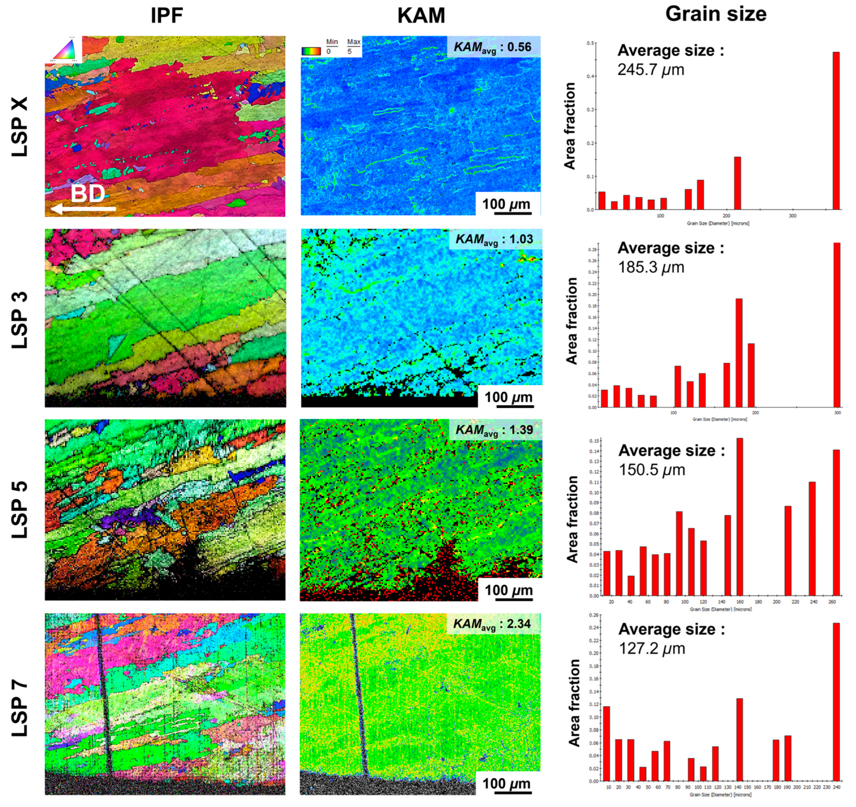
Figure 7 shows EBSD inverse pole figure (IPF) maps, kernel average misorientation (KAM) maps, and average grain size measurements for specimens with 0, 3, 5, and 7 LSP impacts (denoted as LSP X, LSP 3, LSP 5, LSP 7, respectively). In the IPF map of the LSP X specimen, columnar grains are predominantly observed, and a hierarchical microstructure with sub-grains within the columnar grains is present. This complex microstructure is formed due to the thermal history and different cooling rates within the melt pool during the L-DED process, and it has been reported to contain a higher dislocation density compared with conventionally processed microstructures [44]. The KAM map of LSP X (no peening) shows that dislocations are concentrated at sub-grain structures and grain boundaries. However, because the average grain size is as large as ~245.7 μm, there are almost no dislocations in the interiors of those large grains, and the average KAM (KAMavg) is only about 0.56. In contrast, the IPF maps of the LSP 3, 5, and 7 specimens reveal the grain refinement resulting from the plastic deformation induced by LSP. For the LSP 7 specimen, KAMavg reaches 2.34 and the average grain size is refined to ~127.2 μm, indicating that increasing the number of LSP impacts leads to higher dislocation densities and finer grains. Austenitic steels like 316L, which have relatively low stacking fault energy, tend to deform via planar dislocation slip rather than cross-slip or wavy slip modes [45,46]. Such planar slip produces high local dislocation densities, as reflected by the increase in KAMavg from about 0.53 (LSP X) to 2.34 (LSP 7). The increase in dislocation density and grain refinement induced by LSP can not only increase the material’s mechanical strength but also directly affect its resistance to HE. Additionally, grain refinement can enhance the stability of the austenite phase, thereby suppressing martensitic transformations, which is considered detrimental to hydrogen embrittlement resistance [47]. It also reduces the amount of hydrogen concentrated at grain boundaries by increasing total grain boundary area, thereby diminishing the detrimental effects of hydrogen on the grain boundaries and preventing deep penetration of hydrogen into the material. Furthermore, the increase in dislocation density can lead to a more homogeneous distribution of dislocations inside grains, which prevents hydrogen from concentrating at specific weak points and results in higher internal stresses that increase the solubility of hydrogen [14]. Owing to these various factors, the LSP-induced increase in dislocation density and the accompanying grain refinement are concluded to improve the hydrogen embrittlement resistance of the material.
Figure 8 presents the X-ray diffraction patterns of the LSP X, LSP 3, LSP 5, and LSP 7 specimens. Owing to its low tendency for strain-induced phase transformation, 316L stainless steel maintains a high stability of the austenite phase [48]. Accordingly, all specimens in this study remained fully austenitic, with the (111) austenite peak being the most prominent in each XRD pattern. As the number of LSP treatments increased, the intensity of the (111) peak slightly decreased, but no martensite phase peaks appeared in any specimen. Since all samples retained the FCC austenitic structure overall, the hydrogen diffusivity in these materials is expected to remain relatively low.
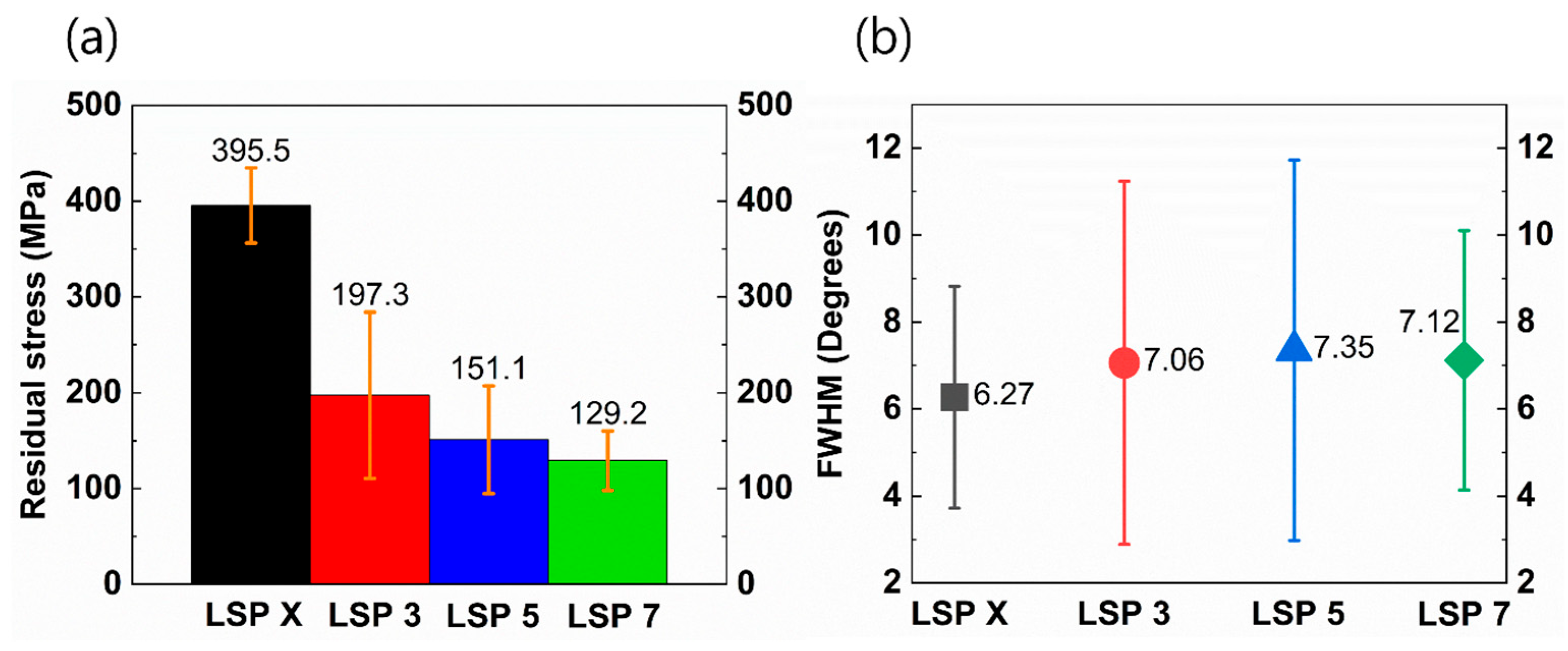
Figure 9a shows the residual stress profiles measured on the surface of specimens before and after LSP treatment. The as-deposited specimen without LSP (LSP X) exhibited a high tensile residual stress of +395.5 MPa at the surface. Additively manufactured components generally contain significant tensile residual stresses as built [49,50]. However, with increasing LSP impacts, the tensile residual stress was continuously reduced. After seven LSP treatments, the surface residual stress decreased to +129.2 MPa, meaning that about 266.3 MPa of tensile stress was relieved compared with the as-built condition. In addition, Figure 9b indicates that the LSP treatments resulted in the broadening of the XRD diffraction peaks, as reflected in an increase in the full width at half maximum (FWHM) from 6.27° (LSP X) to 7.12° (LSP 7). The FWHM of an XRD peak is related to the coherent domain (grain) size according to the following Scherrer equation [51]:
m = λ D cos θ
Here, m is the FWHM of the peak, D is the grain size, λ is the X-ray wavelength, and θ is the incident angle. Using the measured peak broadening, the Scherrer equation indicates that the effective grain size decreased with LSP, consistent with the grain refinement observed by EBSD.
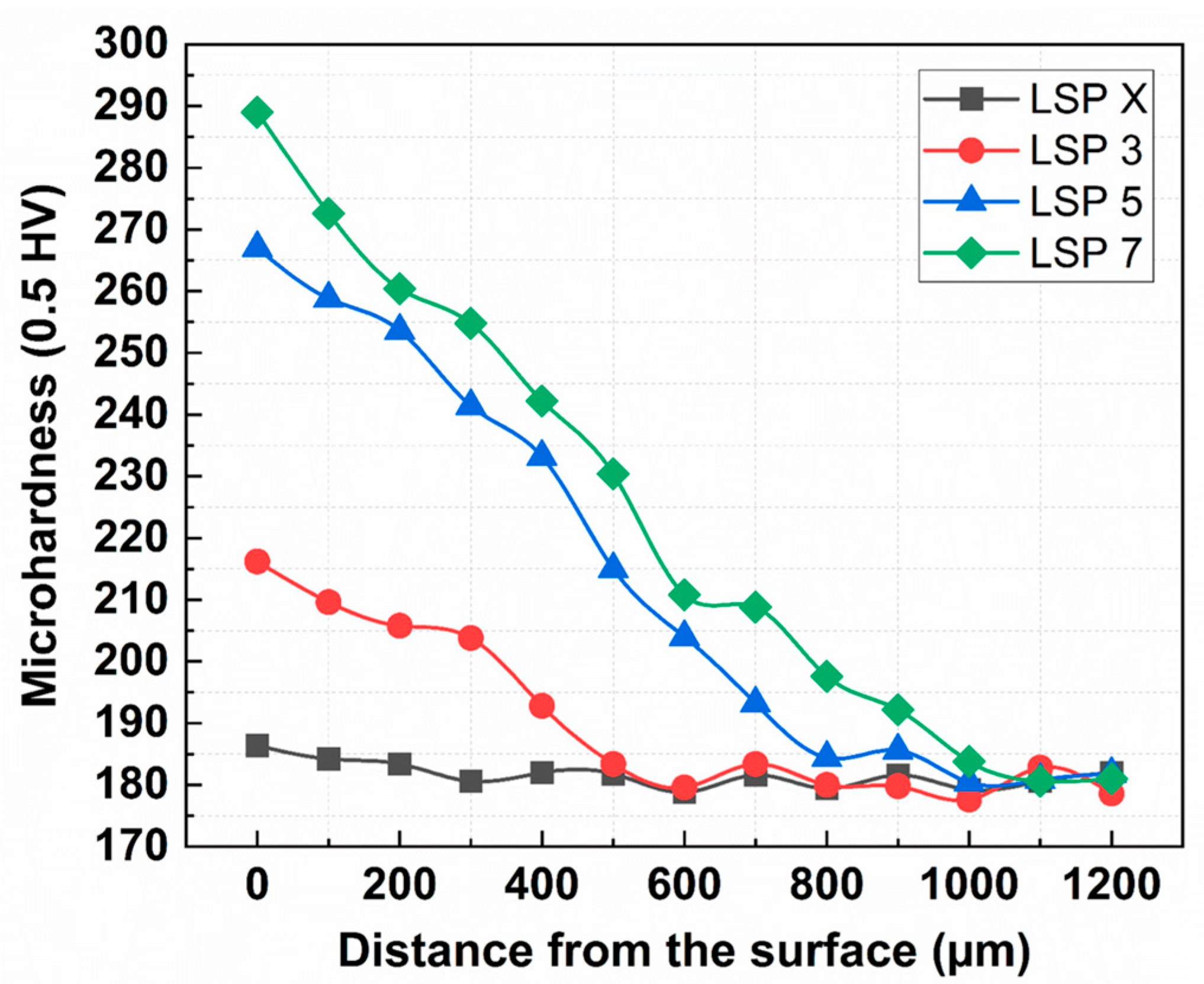
Figure 10 shows the microhardness profiles measured from the surface to a depth of approximately 1200 µm. It is well known that the peening process generally increases surface hardness due to strain hardening effects induced by plastic deformation [52,53]. The surface hardness of the untreated specimen (LSP X) was measured at 186.4 HV, while specimens subjected to 3, 5, and 7 passes of LSP exhibited increased hardness values of 216.2 HV, 267.0 HV, and 289.2 HV, respectively. This corresponds to approximately a 34% increase in surface hardness compared with the untreated condition, clearly demonstrating that hardness increases with the number of LSP treatments. Moreover, conventional shot peening typically produces a work-hardened surface layer to a depth of approximately 200–400 µm [54,55], whereas LSP achieved deeper hardened layers: approximately 400 µm for LSP 3, 900 µm for LSP 5, and 1000 µm for LSP 7. These results indicate that LSP can generate a significantly deeper peening effect compared with conventional shot peening methods. It is known that deeper compressive residual stress layers effectively slow the initiation and propagation of surface cracks, thereby improving hydrogen embrittlement resistance [34]. Therefore, it is expected that LSP, with its deeper peening depth, would offer superior hydrogen embrittlement resistance compared with conventional shot peening.
In general, the presence of a martensitic phase would lead to higher yield strength in stainless steels via transformation-induced hardening [56], but as noted above, no martensite was detected in any of the LSP-treated specimens (Figure 8). Therefore, the strengthening effect of LSP in this study can be attributed to the refined grain structure and increased dislocation density. The Hall–Petch relationship describes how grain refinement contributes to increased yield strength. The Hall–Petch equation is given as follows [57]:
σ 0 = σ i + k D 1 / 2  
Here, σ 0 is the yield stress, σ i is the friction stress, D is the average grain size, and k is a material constant. The strengthening observed with LSP (from ~292 MPa to ~436 MPa yield strength, as will be discussed later) can be attributed to the grain size refinement. Additionally, the reduction in process-induced porosity and other defects by LSP (through the peening action) may have contributed to the improved ductility (elongation) observed in the peened specimens.
To evaluate the effect of LSP on hydrogen embrittlement, SSRT was performed on specimens with and without hydrogen pre-charging. Figure 11a shows the engineering stress–strain curves for LSP X, 3, 5, and 7 specimens tested without the pre-charging, and Figure 11b shows the stress–strain curves for specimens tested after hydrogen charging. The mechanical properties obtained from these curves are summarized in Figure 12 and Table 4. These results indicate that, without hydrogen charging, the LSP-treated specimens maintained higher mechanical strength compared with the untreated (LSP X) specimen. For example, the LSP 7 specimen exhibited a 112.2 MPa increase in yield strength and a 34.4 MPa increase in ultimate tensile strength compared with LSP X. When tested after the hydrogen pre-charging, all the LSP-treated specimens exhibited higher strength and higher elongation than the unpeened specimens. For example, LSP X specimen’s yield strength, tensile strength, and elongation were 292.2 MPa, 519.6 MPa, and 41.0%, respectively, whereas the LSP 7 specimen showed 436.1 MPa, 579.4 MPa, and 46.0%.
The hydrogen embrittlement (HE) resistance was quantitatively evaluated using the HE index, which is defined based on the reduction in elongation after hydrogen charging, as shown in the following formula: ( ( E l u n c h a r g e d E l c h a r g e d ) / E l u n c h a r g e d ) × 100 , where E l u n c h a r g e d and E l c h a r g e d are the fracture strains of H-uncharged and H-charged specimens, respectively [58]. In this study, the HE resistance of the LSP X specimen was approximately 36.1%. As the number of LSP impacts increased, the HE resistance decreased, reaching as low as 12.5% in the LSP 7 specimen. In other words, multiple LSP impacts substantially improved resistance to hydrogen embrittlement.
The LSP X specimen exhibited the highest HE index at 36.1%, while the LSP 7 specimen showed the lowest at 12.5%. The gradual decrease in HE index with increasing LSP passes can be attributed to the microstructural modifications such as the grain refinement, the increased dislocation density, and the relaxation of tensile residual stress. In contrast, the LSP X specimen exhibited relatively coarse grains and a lower dislocation density inside the grains. Furthermore, the residual tensile stress in LSP X reached 395.5 MPa, which exceeds its yield strength, making it more susceptible to premature fracture and defect formation. Consequently, the unpeened as-built specimen even showed the reduction in mechanical strength after the hydrogen charging. Hydrogen can affect the mechanical behavior of metals in different ways. In some cases, hydrogen causes a marked softening of the material [59], while in other cases, an apparent hardening or strengthening effect of hydrogen has been reported [60]. Further studies are required to fully understand the interplay of factors in hydrogen-induced softening or hardening phenomena.
Figure 13 shows fractography of the top surfaces of fracture after the hydrogen pre-charging, under different LSP conditions. As shown in Figure 13a, the unpeened as-built specimen (LSP X) exhibited numerous large surface cracks, possibly originating primarily from the heat-affected zones (HAZs) at the melt-pool boundaries. These areas are susceptible due to the concentration of hydrogen and dislocations during tensile deformation, causing rapid crack initiation and propagation along the boundaries [61]. In contrast, as the number of LSP impacts increased, the size and number of cracks significantly decreased. Especially in the LSP 7 specimen, no visible surface cracks were observed, indicating that repeated LSP effectively suppressed the initiation and propagation of the cracks.
Figure 14 presents fractography of the cross-sectional edges of the SSRT fracture surfaces for the hydrogen pre-charged specimens under different LSP conditions. The fracture morphologies allow for the assessment of the severity and penetration depth of hydrogen embrittlement [62]. While 316L stainless steel typically exhibits ductile fracture features such as dimples [63], hydrogen exposure promoted brittle fracture modes, including quasi-cleavage and cleavage facets. In Figure 14a, the unpeened specimen shows a hydrogen-affected brittle zone extending to approximately 184 μm from the surface, characterized by a combination of cleavage and quasi-cleavage features. In contrast, LSP-treated specimens (Figure 14b–d) exhibited a notable reduction in both the depth and severity of the embrittled region. The depth of the hydrogen-affected zone decreased to 42.1 μm in the LSP 7 specimen. In addition, the fracture morphology transitioned from cleavage in the LSP X specimen to quasi-cleavage in the LSP-treated specimens, indicating reduced severity of hydrogen-induced brittle fracture with increasing LSP passes.
This reduction in the depth and severity of hydrogen embrittlement observed in LSP-treated specimens can be explained by grain refinement, enhanced dislocation density, and the introduction of compressive residual stresses induced by LSP. These microstructural changes effectively hinder hydrogen diffusion and lower hydrogen trapping, thus mitigating hydrogen-assisted crack initiation and propagation.

4. Conclusions

In this study, laser shock peening (LSP) was applied to 316L stainless steel fabricated by laser-directed energy deposition (L-DED) to improve mechanical strength and resistance to hydrogen embrittlement (HE). Based on the experimental results, LSP effectively induced grain refinement and increased dislocation density near the surface, as evidenced by EBSD analysis. In addition, the application of LSP significantly relaxed the tensile residual stress generated during the L-DED process. With increasing LSP passes, the surface stress decreased from +395.5 MPa to +129.2 MPa. Mechanical testing after electrochemical hydrogen charging confirmed that LSP improves both strength and ductility under hydrogen environments. The hydrogen embrittlement index decreased markedly from 36.1% (LSP X) to 12.5% (LSP 7), demonstrating improved resistance to hydrogen-assisted cracking. These results confirm that the possible mechanisms of improvement by LSP are grain refinement, increased dislocation density, and relaxation of tensile residual stress. Thus, LSP is a promising post-treatment technique for enhancing the hydrogen-related performance of additively manufactured 316L stainless steel. Future work will include multiple repetitions for statistical analysis, exploration of a broader range of process parameters, and evaluation of alternative laser impact paths. Long-term hydrogen charging and fatigue tests will also be conducted to assess the durability of LSP-treated L-DED 316L components.

Funding

This work was supported by the Ministry of Science and ICT (2024-22030005-20, RS-2023-00304763) and the Commercialization Promotion Agency for R&D Outcomes (COMPA), Korea Evaluation Institute of Industrial Technology (00448195) grant funded by the Korean government (MOTIE), and Korea Institute of Industrial Technology (JA-25-0006).

Institutional Review Board Statement

Not applicable.

Informed Consent Statement

Not applicable.

Data Availability Statement

The data presented in this study are available on request from the corresponding author.

Conflicts of Interest

The author declares no conflicts of interest. The funders had no role in the design of the study; in the collection, analyses, or interpretation of data; in the writing of the manuscript; or in the decision to publish the results.

References

  1. Niaz, S.; Manzoor, T.; Pandith, A.H. Hydrogen storage: Materials, methods and perspectives. Renew. Sustain. Energy Rev. 2015, 50, 457–469. [Google Scholar] [CrossRef]
  2. Kim, S.-G.; Kim, J.-Y.; Seo, H.-J.; Jung, H.-G.; Park, J.; Baek, U.-B.; Hwang, B. Hydrogen embrittlement characteristics of tempered martensitic steels under electrochemical and high-pressure hydrogen environments. Korean J. Met. Mater. 2023, 61, 807–814. [Google Scholar] [CrossRef]
  3. Ko, S.-W.; Lee, J.-M.; Hwang, B. Effect of nb addition and pre-strain on hydrogen embrittlement of low-carbon steels with ferrite-pearlite structure. Korean J. Met. Mater. 2020, 58, 752–758. [Google Scholar] [CrossRef]
  4. Srinivasan, S.; Demirocak, D.E.; Kaushik, A.; Sharma, M.; Chaudhary, G.R.; Hickman, N.; Stefanakos, E. Reversible hydrogen storage using nanocomposites. Appl. Sci. 2020, 10, 4618. [Google Scholar] [CrossRef]
  5. Abreu Araujo, L.; Rebolledo Ramos, N.; Torres Martín, J.E.; Chinchón-Payá, S.; Sánchez Montero, J.; Lample Carreras, R.M.; Vera-Agullo, J.; Jimenez-Vicaria, J.D. Concrete gas permeability: Implications for hydrogen storage applications. Appl. Sci. 2024, 14, 6408. [Google Scholar] [CrossRef]
  6. Reda, R.; Ataya, S.; Ayman, M.; Saad, K.; Mostafa, S.; Elnady, G.; Khan, R.; Elshaghoul, Y.G. Additively manufactured 316L stainless steel: Hydrogen embrittlement susceptibility and electrochemical gas production. Appl. Sci. 2025, 15, 5824. [Google Scholar] [CrossRef]
  7. Oriani, R. Hydrogen embrittlement of steels. Annu. Rev. Mater. Sci. 1978, 8, 327–357. [Google Scholar] [CrossRef]
  8. Robertson, I.M.; Sofronis, P.; Nagao, A.; Martin, M.L.; Wang, S.; Gross, D.; Nygren, K. Hydrogen embrittlement understood. Metall. Mater. Trans. A 2015, 46, 2323–2341. [Google Scholar] [CrossRef]
  9. Bertsch, K.; Nagao, A.; Rankouhi, B.; Kuehl, B.; Thoma, D. Hydrogen embrittlement of additively manufactured austenitic stainless steel 316 L. Corros. Sci. 2021, 192, 109790. [Google Scholar]
  10. Lynch, S. Mechanistic and fractographic aspects of stress corrosion cracking. Corros. Rev. 2012, 30, 63–104. [Google Scholar] [CrossRef]
  11. Martin, M.L.; Fenske, J.A.; Liu, G.S.; Sofronis, P.; Robertson, I.M. On the formation and nature of quasi-cleavage fracture surfaces in hydrogen embrittled steels. Acta Mater. 2011, 59, 1601–1606. [Google Scholar] [CrossRef]
  12. Murakami, Y.; Kanezaki, T.; Mine, Y. Hydrogen effect against hydrogen embrittlement. Metall. Mater. Trans. A 2010, 41, 2548–2562. [Google Scholar] [CrossRef]
  13. Dwivedi, S.K.; Vishwakarma, M. Hydrogen embrittlement in different materials: A review. Int. J. Hydrogen Energy 2018, 43, 21603–21616. [Google Scholar] [CrossRef]
  14. Claeys, L.; Deconinck, L.; Verbeken, K.; Depover, T. Effect of additive manufacturing and subsequent heat and/or surface treatment on the hydrogen embrittlement sensitivity of 316L austenitic stainless steel. Int. J. Hydrogen Energy 2023, 48, 36142–36157. [Google Scholar] [CrossRef]
  15. Hong, Y.; Zhou, C.; Zheng, Y.; Zhang, L.; Zheng, J.; Chen, X.; An, B. Formation of strain-induced martensite in selective laser melting austenitic stainless steel. Mater. Sci. Eng. A 2019, 740, 420–426. [Google Scholar] [CrossRef]
  16. Chen, J.; Wei, H.; Bao, K.; Zhang, X.; Cao, Y.; Peng, Y.; Kong, J.; Wang, K. Dynamic mechanical properties of 316L stainless steel fabricated by an additive manufacturing process. J. Mater. Res. Technol. 2021, 11, 170–179. [Google Scholar] [CrossRef]
  17. Bartolomeu, F.; Buciumeanu, M.; Pinto, E.; Alves, N.; Carvalho, O.; Silva, F.; Miranda, G. 316L stainless steel mechanical and tribological behavior—A comparison between selective laser melting, hot pressing and conventional casting. Addit. Manuf. 2017, 16, 81–89. [Google Scholar] [CrossRef]
  18. Tan, C.; Chew, Y.; Duan, R.; Weng, F.; Sui, S.; Ng, F.L.; Du, Z.; Bi, G. Additive manufacturing of multi-scale heterostructured high-strength steels. Mater. Res. Lett. 2021, 9, 291–299. [Google Scholar] [CrossRef]
  19. Singh, S.N.; Deoghare, A.B. Laser shock peening of laser based directed energy deposition and powder bed fusion additively manufactured parts: A review. Met. Mater. Int. 2023, 29, 1563–1585. [Google Scholar] [CrossRef]
  20. Kang, N.; Lin, X.; El Mansori, M.; Wang, Q.; Lu, J.; Coddet, C.; Huang, W. On the effect of the thermal cycle during the directed energy deposition application to the in-situ production of a ti-mo alloy functionally graded structure. Addit. Manuf. 2020, 31, 100911. [Google Scholar] [CrossRef]
  21. Huang, S.; Ma, D.; Sheng, J.; Agyenim-Boateng, E.; Zhao, J.; Zhou, J. Effects of laser peening on tensile properties and martensitic transformation of aisi 316L stainless steel in a hydrogen-rich environment. Mater. Sci. Eng. A 2020, 788, 139543. [Google Scholar] [CrossRef]
  22. Leuders, S.; Meiners, S.; Wu, L.; Taube, A.; Tröster, T.; Niendorf, T. Structural components manufactured by selective laser melting and investment casting—Impact of the process route on the damage mechanism under cyclic loading. J. Mater. Process. Technol. 2017, 248, 130–142. [Google Scholar] [CrossRef]
  23. AlMangour, B.; Yang, J.-M. Improving the surface quality and mechanical properties by shot-peening of 17-4 stainless steel fabricated by additive manufacturing. Mater. Des. 2016, 110, 914–924. [Google Scholar] [CrossRef]
  24. Ouyang, P.; Dong, Z.; Luo, X.; Zhang, S.; Liu, L.; Sun, B.; Zhou, L. Effect of combined treatment of laser shock peening and shot peening on fatigue performance of laser-powder-bed-fusioned gh4169 nickel-based alloy. Opt. Laser Technol. 2025, 182, 112141. [Google Scholar] [CrossRef]
  25. Zha, X.; Xi, L.; Guo, Y.; Chen, X.; Chen, X.; Guo, B.; Li, Y.; Xu, Z.; Jiang, F. Investigation on mechanical properties and surface strengthening mechanism of the cemented carbide processed by laser shock peening. J. Mater. Res. Technol. 2025, 35, 2119–2135. [Google Scholar] [CrossRef]
  26. Li, X.-f.; Zhang, J.; Ma, M.-m.; Song, X.-l. Effect of shot peening on hydrogen embrittlement of high strength steel. Int. J. Miner. Metall. Mater. 2016, 23, 667–675. [Google Scholar] [CrossRef]
  27. Hui, W.; Zhang, Y.; Zhao, X.; Shao, C.; Wang, K.; Sun, W.; Yu, T. Influence of cold deformation and annealing on hydrogen embrittlement of cold hardening bainitic steel for high strength bolts. Mater. Sci. Eng. A 2016, 662, 528–536. [Google Scholar] [CrossRef]
  28. Chen, C.; Xie, Y.; Yan, X.; Yin, S.; Fukanuma, H.; Huang, R.; Zhao, R.; Wang, J.; Ren, Z.; Liu, M. Effect of hot isostatic pressing (hip) on microstructure and mechanical properties of ti6al4v alloy fabricated by cold spray additive manufacturing. Addit. Manuf. 2019, 27, 595–605. [Google Scholar] [CrossRef]
  29. Álvarez, G.; Harris, Z.; Wada, K.; Rodríguez, C.; Martínez-Pañeda, E. Hydrogen embrittlement susceptibility of additively manufactured 316L stainless steel: Influence of post-processing, printing direction, temperature and pre-straining. Addit. Manuf. 2023, 78, 103834. [Google Scholar] [CrossRef]
  30. Wang, Y.; Wu, X.; Zhou, Z.; Li, X. Numerical analysis of hydrogen transport into a steel after shot peening. Results Phys. 2018, 11, 5–16. [Google Scholar] [CrossRef]
  31. Takeda, S.; Ohara, Y.; Uchimoto, T.; Enoki, H.; Iijima, T.; Tokuda, E.; Yamada, T.; Nagatomo, Y. Characterization of fatigue crack of hydrogen-charged austenitic stainless steel by electromagnetic and ultrasonic techniques. Int. J. Hydrogen Energy 2022, 47, 32223–32234. [Google Scholar] [CrossRef]
  32. Peyre, P.; Scherpereel, X.; Berthe, L.; Carboni, C.; Fabbro, R.; Béranger, G.; Lemaitre, C. Surface modifications induced in 316L steel by laser peening and shot-peening. Influence on pitting corrosion resistance. Mater. Sci. Eng. A 2000, 280, 294–302. [Google Scholar] [CrossRef]
  33. Shin, D.-H.; Kim, S.-J. Effect of hydrogen embrittlement on mechanical characteristics of dlc-coating for hydrogen valves of fcevs. npj Mater. Degrad. 2024, 8, 47. [Google Scholar] [CrossRef]
  34. Agyenim-Boateng, E.; Huang, S.; Sheng, J.; Yuan, G.; Wang, Z.; Zhou, J.; Feng, A. Influence of laser peening on the hydrogen embrittlement resistance of 316L stainless steel. Surf. Coat. Technol. 2017, 328, 44–53. [Google Scholar] [CrossRef]
  35. Sun, R.; Li, L.; Zhu, Y.; Zhang, L.; Guo, W.; Peng, P.; Li, B.; Guo, C.; Liu, L.; Che, Z. Dynamic response and residual stress fields of ti6al4v alloy under shock wave induced by laser shock peening. Modell. Simul. Mater. Sci. Eng. 2017, 25, 065016. [Google Scholar] [CrossRef]
  36. Peyre, P.; Fabbro, R.; Merrien, P.; Lieurade, H. Laser shock processing of aluminium alloys. Application to high cycle fatigue behaviour. Mater. Sci. Eng. A 1996, 210, 102–113. [Google Scholar] [CrossRef]
  37. Pan, X.; Zhou, L.; Wang, C.; Yu, K.; Zhu, Y.; Yi, M.; Wang, L.; Wen, S.; He, W.; Liang, X. Microstructure and residual stress modulation of 7075 aluminum alloy for improving fatigue performance by laser shock peening. Int. J. Mach. Tools Manuf. 2023, 184, 103979. [Google Scholar] [CrossRef]
  38. Fabbro, R.; Fournier, J.; Ballard, P.; Devaux, D.; Virmont, J. Physical study of laser-produced plasma in confined geometry. J. Appl. Phys. 1990, 68, 775–784. [Google Scholar] [CrossRef]
  39. Xu, G.; Luo, K.; Dai, F.; Lu, J. Effects of scanning path and overlapping rate on residual stress of 316L stainless steel blade subjected to massive laser shock peening treatment with square spots. Appl. Surf. Sci. 2019, 481, 1053–1063. [Google Scholar] [CrossRef]
  40. Peyre, P.; Berthe, L.; Scherpereel, X.; Fabbro, R. Laser-shock processing of aluminium-coated 55c1 steel in water-confinement regime, characterization and application to high-cycle fatigue behaviour. J. Mater. Sci. 1998, 33, 1421–1429. [Google Scholar] [CrossRef]
  41. Berthe, L.; Fabbro, R.; Peyre, P.; Tollier, L.; Bartnicki, E. Shock waves from a water-confined laser-generated plasma. J. Appl. Phys. 1997, 82, 2826–2832. [Google Scholar] [CrossRef]
  42. Li, Y.; Li, Y.; Wang, X.; Xu, W.; Qiao, F.; Wang, S. Effect of nanosecond pulse laser shock peening on the microstructure and performance of welded joint of 316L stainless steel. In Proceedings of the Chinese Materials Conference, Yinchuan, China, 6–12 July 2017; pp. 113–125. [Google Scholar]
  43. Glaser, D.; Polese, C.; Venter, A.; Marais, D.; Plaisier, J. Evaluation of laser shock peening process parameters incorporating almen strip deflections. Surf. Coat. Technol. 2022, 434, 128158. [Google Scholar] [CrossRef]
  44. Zheng, B.; Haley, J.; Yang, N.; Yee, J.; Terrassa, K.; Zhou, Y.; Lavernia, E.; Schoenung, J. On the evolution of microstructure and defect control in 316L ss components fabricated via directed energy deposition. Mater. Sci. Eng. A 2019, 764, 138243. [Google Scholar] [CrossRef]
  45. Gaudin, C.; Feaugas, X. Cyclic creep process in aisi 316L stainless steel in terms of dislocation patterns and internal stresses. Acta Mater. 2004, 52, 3097–3110. [Google Scholar] [CrossRef]
  46. Feaugas, X. On the origin of the tensile flow stress in the stainless steel aisi 316L at 300 k: Back stress and effective stress. Acta Mater. 1999, 47, 3617–3632. [Google Scholar] [CrossRef]
  47. Mirzadeh, H.; Najafizadeh, A. Correlation between processing parameters and strain-induced martensitic transformation in cold worked aisi 301 stainless steel. Mater. Charact. 2008, 59, 1650–1654. [Google Scholar] [CrossRef]
  48. San Marchi, C.; Somerday, B.; Tang, X.; Schiroky, G. Effects of alloy composition and strain hardening on tensile fracture of hydrogen-precharged type 316 stainless steels. Int. J. Hydrogen Energy 2008, 33, 889–904. [Google Scholar] [CrossRef]
  49. Li, L.; Zhang, X.; Cui, W.; Liou, F.; Deng, W.; Li, W. Temperature and residual stress distribution of fgm parts by ded process: Modeling and experimental validation. Int. J. Adv. Manuf. Technol. 2020, 109, 451–462. [Google Scholar] [CrossRef]
  50. Smudde, C.M.; San Marchi, C.W.; Hill, M.R.; Gibeling, J.C. Effects of residual stress on orientation dependent fatigue crack growth rates in additively manufactured stainless steel. Int. J. Fatigue 2023, 169, 107489. [Google Scholar] [CrossRef]
  51. Vashista, M.; Paul, S. Correlation between full width at half maximum (fwhm) of xrd peak with residual stress on ground surfaces. Philos. Mag. 2012, 92, 4194–4204. [Google Scholar] [CrossRef]
  52. Wu, J.; Liu, H.; Wei, P.; Zhu, C.; Lin, Q. Effect of shot peening coverage on hardness, residual stress and surface morphology of carburized rollers. Surf. Coat. Technol. 2020, 384, 125273. [Google Scholar] [CrossRef]
  53. Zhu, L.; Guan, Y.; Wang, Y.; Xie, Z.; Lin, J. Influence of process parameters of ultrasonic shot peening on surface nanocrystallization and hardness of pure titanium. Int. J. Adv. Manuf. Technol. 2017, 89, 1451–1468. [Google Scholar] [CrossRef]
  54. Child, D.; West, G.; Thomson, R. Assessment of surface hardening effects from shot peening on a ni-based alloy using electron backscatter diffraction techniques. Acta Mater. 2011, 59, 4825–4834. [Google Scholar] [CrossRef]
  55. Lin, Q.; Liu, H.; Zhu, C.; Parker, R.G. Investigation on the effect of shot peening coverage on the surface integrity. Appl. Surf. Sci. 2019, 489, 66–72. [Google Scholar] [CrossRef]
  56. Eskandari, M.; Najafizadeh, A.; Kermanpur, A. Effect of strain-induced martensite on the formation of nanocrystalline 316L stainless steel after cold rolling and annealing. Mater. Sci. Eng. A 2009, 519, 46–50. [Google Scholar] [CrossRef]
  57. Alam, M.T.; Ahmad, T.; Alshoaibi, A.M.; Aziz, A.; Husain, D.; Ahmad, S. Comprehensive study on the properties of az91/x-si3n4 composites for their prospective application. Appl. Sci. 2024, 14, 4444. [Google Scholar] [CrossRef]
  58. Astafurova, E.; Maier, G.; Melnikov, E.; Moskvina, V.; Vojtsik, V.; Zakharov, G.; Smirnov, A.; Bataev, V. Effect of hydrogen charging on mechanical twinning, strain hardening, and fracture of ‹111› and ‹144› hadfield steel single crystals. Phys. Mesomech. 2018, 21, 263–273. [Google Scholar] [CrossRef]
  59. Li, S.-H.; Lee, D.-H.; Zhao, Y.; Ramamurty, U. Hydrogen-induced softening and embrittlement in 316L stainless steel fabricated using laser-powder bed fusion. Acta Mater. 2024, 274, 119959. [Google Scholar] [CrossRef]
  60. Song, Y.; Huang, S.; Sheng, J.; Agyenim-Boateng, E.; Jiang, Y.; Liu, Q.; Zhu, M. Improvement of hydrogen embrittlement resistance of 2205 duplex stainless steel by laser peening. Int. J. Hydrogen Energy 2023, 48, 18930–18945. [Google Scholar] [CrossRef]
  61. Koyama, M.; Akiyama, E.; Tsuzaki, K.; Raabe, D. Hydrogen-assisted failure in a twinning-induced plasticity steel studied under in situ hydrogen charging by electron channeling contrast imaging. Acta Mater. 2013, 61, 4607–4618. [Google Scholar] [CrossRef]
  62. San Marchi, C.; Somerday, B.P.; Robinson, S.L. Permeability, solubility and diffusivity of hydrogen isotopes in stainless steels at high gas pressures. Int. J. Hydrogen Energy 2007, 32, 100–116. [Google Scholar] [CrossRef]
  63. Matsuo, T.; Yamabe, J.; Matsuoka, S. Effects of hydrogen on tensile properties and fracture surface morphologies of type 316L stainless steel. Int. J. Hydrogen Energy 2014, 39, 3542–3551. [Google Scholar] [CrossRef]
Figure 1. (a) SEM image of the 316L stainless steel powder and (b) particle size distribution of the 316L stainless steel powder.
Applsci 15 09481 g001
Figure 2. (a) Photograph of the actual deposition process and (b) schematic diagram illustrating the scanning strategy and dimensions of the as-built blocks.
Applsci 15 09481 g002
Figure 3. (a) Dimensioned drawing of the tensile test specimen; (b) orientation of the tensile specimens fabricated from the as-built blocks.
Applsci 15 09481 g003
Figure 4. Schematic diagram of laser shock peening experiment setup.
Applsci 15 09481 g004
Figure 5. (a) Photograph of the tensile specimen after the laser shock peening (LSP) and (b) schematic diagram of the LSP-treated region and the applied zigzag scanning path.
Applsci 15 09481 g005
Figure 6. Experimental workflow of sample preparation, hydrogen charging, and mechanical testing and materials characterization.
Applsci 15 09481 g006
Figure 7. EBSD inverse pole figure (IPF) maps, kernel average misorientation (KAM) maps, and average grain size measurements for specimens with 0, 3, 5, and 7 passes of the LSP (denoted LSP X, LSP 3, LSP 5, and LSP 7, respectively).
Applsci 15 09481 g007
Figure 8. X-ray diffraction patterns for untreated (LSP X) and laser shock peened specimens (LSP 3, LSP 5, LSP 7).
Applsci 15 09481 g008
Figure 9. (a) Residual stress and (b) FWHM for untreated (LSP X) and laser shock peened specimens (LSP 3, LSP 5, LSP 7).
Applsci 15 09481 g009
Figure 10. Microhardness depth profiles for untreated (LSP X) and laser shock peened specimens (LSP 3, LSP 5, LSP 7).
Applsci 15 09481 g010
Figure 11. Engineering stress–strain curves of L-DED 316L stainless steel specimens subjected to different numbers of LSP passes: (a) without hydrogen pre-charging and (b) after hydrogen pre-charging. LSP X, 3, 5, and 7 denote specimens with 0, 3, 5, and 7 passes of laser shock peening, respectively.
Applsci 15 09481 g011
Figure 12. Mechanical properties of L-DED 316L stainless steel specimens subjected to different numbers of laser shock peening (LSP) passes (LSP X, 3, 5, and 7) tested without hydrogen pre-charging (black) and with hydrogen pre-charging (red): (a) yield strength, (b) ultimate tensile strength (UTS), and (c) elongation.
Applsci 15 09481 g012
Figure 13. Fractography of the specimens obtained by SSRT after hydrogen charging with different LSP conditions: (a) LSP X, (b) LSP 3, (c) LSP 5, and (d) LSP 7.
Applsci 15 09481 g013
Figure 14. High-magnification SEM images of near-surface fracture regions after hydrogen charging with different LSP conditions: (a) LSP X, (b) LSP 3, (c) LSP 5, and (d) LSP 7.
Applsci 15 09481 g014
Table 1. Chemical composition of the 316L stainless steel powder (wt.%).
PowderFeCCrNiMoSiAlMn
SUS 316LBal.0.02716.9510.082.420.550.331.40
Table 2. Build parameters employed in the L-DED process.
ParametersValue
Laser power (W)1600
Scan speed (mm/min)1000
Powder feed rate (g/min)12
Laser thickness (mm)1
Overlap (mm)1.5
Spot size (mm)3
Table 3. Parameters employed in the LSP process.
ParametersValue
Laser power density (GW/cm2)5.54
Laser induced pressure (GPa)1.98
Laser pulse energy (mJ)2000
Pulse duration (ns)11.5
Repetition rate (Hz)10
Scan speed (mm/s)10
Pulse overlap (mm)1
Spot size (mm)2
Table 4. Mechanical properties of specimens subjected to different LSP conditions with and without hydrogen pre-charging.
Without Hydrogen Pre-ChargingWith Hydrogen Pre-Charging
SpecimenYield StrengthTensile StrengthElongationSpecimenYield StrengthTensile StrengthElongationHE Index
LSP X297.8 MPa542.1 MPa64.2%LSP X_H292.2 MPa519.6 MPa41.0%36.1%
LSP 3331.7 MPa543.4 MPa71.1%LSP 3_H384.2 MPa560.6 MPa53.0%25.5%
LSP 5415.4 MPa567.0 MPa60.4%LSP 5_H427.0 MPa575.9 MPa50.0%17.2%
LSP 7410.0 MPa576.5 MPa52.6%LSP 7_H436.1 MPa579.4 MPa46.0%12.5%
Disclaimer/Publisher’s Note: The statements, opinions and data contained in all publications are solely those of the individual author(s) and contributor(s) and not of MDPI and/or the editor(s). MDPI and/or the editor(s) disclaim responsibility for any injury to people or property resulting from any ideas, methods, instructions or products referred to in the content.