Article

Enhanced Performance of Inverted Perovskite Solar Cells Employing NiOx and Cu-Doped NiOx Nanoparticle Hole Transport Layers

by
Ponmudi Selvan Thiruchelvan
1,
Chien-Chih Lai
2,3 and
Chih-Hung Tsai
3,*
1
Department of Physics, Hindustan Institute of Technology and Science, Chennai 603103, Tamilnadu, India
2
Department of Physics, National Dong Hwa University, Hualien 97401, Taiwan
3
Department of Opto-Electronic Engineering, National Dong Hwa University, Hualien 97401, Taiwan
*
Author to whom correspondence should be addressed.
Appl. Sci. 2025, 15(21), 11449; https://doi.org/10.3390/app152111449
Submission received: 5 October 2025 / Revised: 23 October 2025 / Accepted: 24 October 2025 / Published: 27 October 2025

Abstract

In this study, p-type NiOx and Cu-doped NiOx nanoparticles (NPs) were synthesized by a simple chemical precipitation method and used as hole transport layers (HTLs) for inverted perovskite solar cells (PSCs). The microstructural property, surface morphology, elemental composition, optical property, charge recombination, and surface topography of the NiOx and Cu-NiOx HTLs were comprehensively characterized. The results showed that the NiOx and Cu-NiOx NPs were uniformly coated on the substrates without pinholes or voids. Cu incorporation into NiOx did not change its crystalline nature and considerably improved its electrical conductivity. The Cu-NiOx HTLs exhibited superior photoluminescence quenching and the least lifetime decay, which indicated that Cu-NiOx exhibited higher charge transport than NiOx HTLs. The fabricated PSC performances were further analyzed using current density–voltage characteristics, external quantum efficiency, and electrochemical impedance spectroscopy. The PSCs with PEDOT:PSS, NiOx, and 2% Cu-NiOx HTLs exhibited power conversion efficiencies of 11.93%, 13.72%, and 15.54%, respectively. The 2% Cu-NiOx HTL-based device showed the best performance compared with the PEDOT:PSS- and NiOx-based devices. Academic Editors: Chunyang Zhang, Dou Zhang

1. Introduction

Organic and inorganic metal halide perovskites have emerged as pivotal materials in optoelectronic applications due to their high charge-carrier mobility, strong light absorption, and tunable bandgap. Moreover, they have the potential to expand their applications into diverse fields such as photocatalysis [1], energy storage [2], and advanced computing and memory (memristors) [3]. Over the past decade, perovskite solar cells (PSCs) have attracted significant attention owing to their rapidly increasing power conversion efficiency and potential for commercialization [4,5,6]. Structurally, PSCs are generally categorized into two configurations: conventional (n–i–p) and inverted (p–i–n). Although conventional PSCs are efficient, they are highly susceptible to hysteresis and thermal instability and are expensive. Inverted PSCs exhibit limited hysteresis and excellent stability but inferior PCE. Nevertheless, inverted PSCs have attracted considerable research interest because of their simple fabrication processes and suitability for use in flexible devices due to their low-temperature processing. The performance of inverted PSCs can be improved through hole transport layer (HTL) engineering. The requirements of PSCs are high optical transparency, hole mobility, and energy alignment with the perovskite layers.
In inverted PSCs, poly(3,4-(ethylenedioxy)thiophene)/poly(styrene sulfonate) (PEDOT:PSS) HTLs are common. However, these HTLs are hygroscopic and acidic, which severely affects PSC stability. Therefore, metal oxides are an ideal candidate for replacing organic HTLs. NiOx is the most widely studied HTL material because of its excellent p-type semiconducting property, high transparency, and numerous deposition methods. In 2014, Jeng et al. first introduced NiOx HTLs in PSCs as a replacement for PEDOT:PSS [7]. Several researchers have since developed NiOx thin films for PSCs by using various methods such as those using the sol–gel process, combustion, nanoparticle (NP) ink, chemical bath deposition, electrodeposition, spray pyrolysis, sputtering, electron-beam physical vapor deposition process, and pulsed-laser deposition [8,9,10,11,12,13,14,15,16,17,18,19,20,21,22,23]. Low-temperature fabrication methods are attractive because they are suitable for fabricating flexible devices. NiOx HTLs are typically prepared using a low-temperature (150 °C) combustion method. NiOx HTLs prepared from NP ink are easy to fabricate and exhibit higher crystallinity than those prepared with other techniques. This method can be readily adapted for the doping of other metals to improve the hole mobility of the NiOx layer. This improvement is crucial because NiOx is limited because of its electrical property and exhibits lower hole mobility, valence band maximum, and more surface defects than (PEDOT:PSS) HTLs. Techniques such as doping and surface modification have been proposed to improve the conductivity and charge collection of NiOx HTLs [24,25,26,27]. Metal doping is the best surface modification approach for improving the electrical properties of NiOx HTLs. Many researchers have reported doping NiOx with metals such as Li, Cu, Mg, Co, Cs, and Fe [28,29,30,31,32].
Cu doping has attracted considerable research attention because of its high carrier concentration, mobility, and work function [33]. Several reports have demonstrated PCEs exceeding 23% in inverted perovskites solar cells through strategies such as multi-cation incorporation at the A-site, the use of two-dimensional (2D) perovskites, and interface engineering at both the HTL and the ETL [34,35]. In this work, we focus on the incorporation of Cu at the Ni site to enhance the electrical properties and overall device performance by modifying the HTL without any heating or annealing during the fabrication process, except for the perovskite film. We fabricated inverted PSCs with presynthesized NiOx NP and Cu-doped NiOx (Cu-NiOx) NP HTLs. The device structure was Glass/FTO/NiOx or Cu-NiOx or PEDOT:PSS/perovskite/PCBM/BCP/Ag, as shown in Figure 1a, and its equivalent energy level diagram is displayed in Figure 1b. A simple chemical precipitation technique was used to prepare NiOx NPs. The synthesized NPs were characterized through X-ray diffraction (XRD), X-ray photoelectron spectroscopy (XPS), field emission scanning electron microscopy (FESEM), ultraviolet (UV)–visible (Vis) spectroscopy, photoluminescence (PL) spectroscopy, and atomic force microscopy (AFM). The performance of the fabricated device was characterized using current density–voltage (J–V) analysis, electrochemical impedance spectroscopy (EIS), and external quantum efficiency (EQE). The fabricated Cu-NiOx PSCs exhibited improved performance. The PSCs fabricated using 2% Cu-NiOx NP inks, with a PCE of 15.54%, exhibited the highest efficiency. The device fabricated using pristine NiOx and PEDOT:PSS exhibited PCEs of 13.72% and 11.93%, respectively.

2. Experimental Details

2.1. Synthesis of NiO and Cu-Doped NiO NPs

First, 0.4 M nickel nitrate hexahydrate (Ni(NO3)2 6H2O) (CHONEYE PURE CHEMICALS, Miaoli County, Taiwan, Purity > 98%) was dissolved in deionized (DI) water to obtain a green solution. Then, 10 M sodium hydroxide (NaOH) was added dropwise till the solution reached a pH of 10. The precipitate was stirred for 30 min, centrifuged at 16,000 rpm for 10 min, and washed with DI water three times. The green powders were dried at 80 °C overnight and calcined at 270 °C for 2 h at a 5 °C/min ramping rate. Finally, NiOx NPs in the form of black powder were obtained. The NPs were dispersed in DI water at a 20 mg/mL concentration. For Cu doping, various mole percentages of nickel nitrate were replaced by Copper(II) nitrate trihydrate Cu(NO3)2 3H2O (CHONEYE PURE CHEMICALS, Miaoli County, Taiwan, Purity > 98%). Other procedures were the same as those for the undoped NiOx NPs.

2.2. PSC Device Fabrication

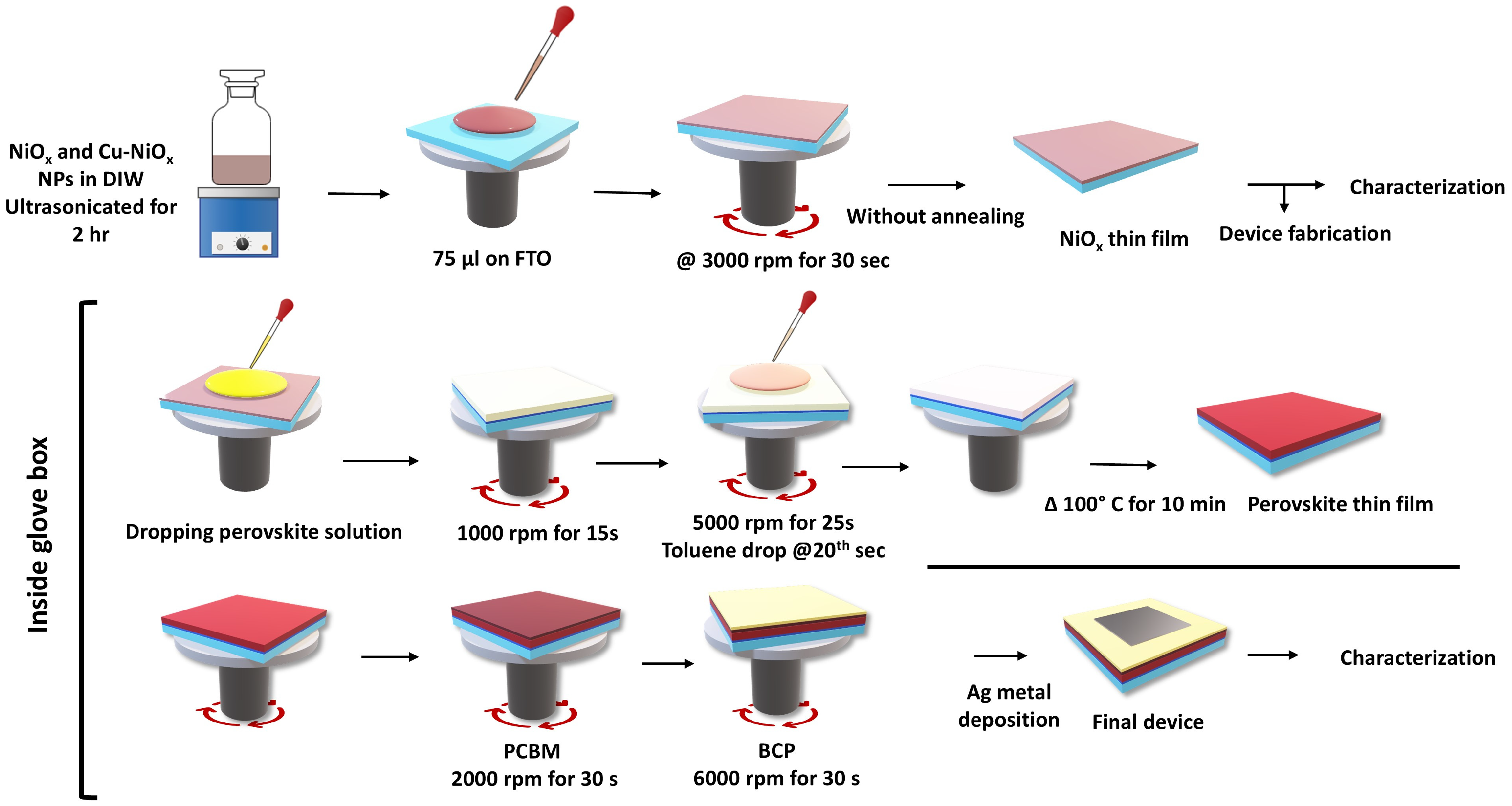
The schematic of PSC device fabrication is represented in Figure 2. FTO substrates (Ruilong Optoelectronics Co., Ltd, Miaoli County, Taiwan) were patterned and cleaned in an ultrasonic bath using detergent, acetone, and isopropyl alcohol (IPA) for 10 min. Then, the substrates were dried using a nitrogen gun and UV–ozone treated for 15 min. The HTL production method was as follows: NiOx (or Cu-NiOx) NP ink was spin-coated onto the FTO substrates at a speed of 3000 rpm for 30 s. We also fabricated devices with a PEDOT:PSS HTL for comparison. The PEDOT:PSS (UNI-ONWARD Corp, New Taipei City, Taiwan) was spin-coated at 4000 rpm for 30 s and annealed at 140 °C for 10 min. Subsequently, the perovskite active layer was produced through the following procedures: 1.4 M MAI (UNI-ONWARD Corp, New Taipei City, Taiwan) and 1.4 M PbI2 (UNI-ONWARD Corp, New Taipei City, Taiwan) were dissolved in a mixed solvent of GBL/DMSO in a 7:3 ratio. The perovskite solution was stirred at 60 °C overnight and filtered using a 0.45 µm PTFE syringe filter before deposition. The solution was spin-coated onto the FTO/NiOx substrates at 1000 rpm for 15 s and 5000 rpm for 25 s. Toluene was used as an antisolvent and was added exactly 5 s before the end of the second step. The substrates were annealed at 100 °C for 10 min. The electron transport layer (ETL) production process was as follows: 20 mg/mL of phenyl-C61-butyric acid methyl ester (PCBM) in 1,4-dichlorobenzene was spin-coated on the substrates at 2000 rpm for 30 s, and a saturated solution of BCP in methanol was spin-coated at 6000 rpm for 30 s. No annealing process was performed during fabrication, except for the perovskite film. Finally, a Ag electrode was evaporated through thermal evaporation.

2.3. Characterization

NiOx and Cu-NiOx were characterized through XRD (Rigaku D/Max-2500V, Rigaku Corp, Tokyo, Japan); their surface morphology was observed through FESEM (JEOL JSM-7000F, JEOL Inc., Tokyo, Japan), and their surface topography was measured through AFM (AutoProbe CP, Thermomicroscopes, Sunnyvale, CA, USA). Moreover, elemental analysis was performed through XPS (Thermo K-Alpha, Thermo Fisher Scientific, Waltham, MA, USA). UV-Vis absorption and transmission were measured through a UV-Vis spectrophotometer (Jasco V-650, Jasco, Tokyo, Japan). PL and lifetime measurements were performed using a solid-state laser (λ = 405 nm, PDL 800-D, PICOQUANT) equipped with a homemade laser scanning confocal microscope and a spectrometer equipped with a thermoelectrically cooled charge-coupled detector (DV420A-BU2, Andor, Belfast, Northern Ireland). The performance of the fabricated PSC device was analyzed using J–V curves (CH 6116D, CH Instruments, Bee Cave, TX, USA), EQE (QE-R, Enlitech, Kaohsiung, Taiwan), and EIS. The J–V characteristics of the PSCs were measured under the illumination of a simulated AM 1.5G solar spectrum from a 550-W Xe lamp solar simulator (Abet Technologies Sun 3000 Class AAA, Abet Technologies, Milford, CT, USA).

3. Results and Discussion

3.1. Chemical Reaction Mechanism of NiOx and Cu-NiOx NPs

The NiOx and Cu-NiOx NPs were synthesized using a simple chemical precipitation method according to procedures reported in studies [36,37,38,39,40,41,42] with some modifications (see details in the experimental section). We synthesized pristine NiOx NPs and 2%, 4%, and 8% Cu-NiOx NPs. HTL development using simple synthesis methods is promising for the large-scale industrial production of PSCs. The chemical reaction mechanism of nonstoichiometric NiOx NPs and Cu-NiOx NPs is expressed in Equations (1)–(4), respectively.
N i N O 3 + N a O H N i ( O H ) 2 +   N a ( N O 3 ) 2
N i ( O H ) 2 270   ° C N i O x + H 2 O
N i N O 3 +   C u N O 3 +   N a O H N i ( O H ) 2 +   C u ( O H ) 2 +   N a ( N O 3 ) 2
N i ( O H ) 2 + C u ( O H ) 2 270   ° C C u d o p e d   N i O x +   H 2 O
The calcination temperature was set at 270 °C to ensure the thermal decomposition of Ni(OH)2 to nonstoichiometric NiOx NPs. However, Ni(OH)2 cannot completely decompose to NiO at a temperature lower than the calcination temperature of 270 °C. Because Ni(OH)2 is electrically insulated, it cannot be easily dispersed in solvents. If the calcination temperature exceeds 270 °C, the particle size increases. Both cases are not suitable for making an effective HTL for PSCs.

3.2. Characterization of the HTLs

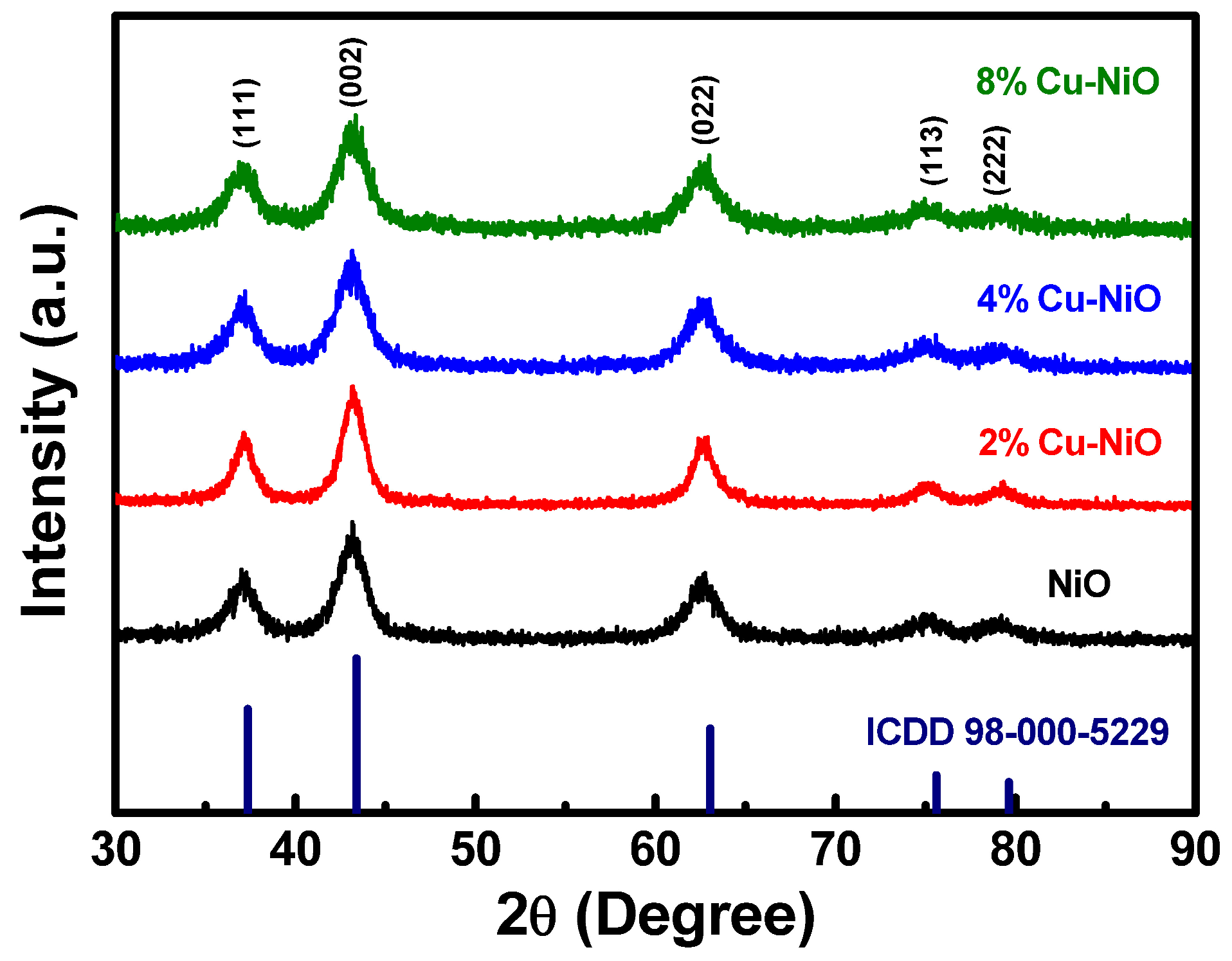
XRD patterns for pristine NiOx and various percentages of Cu-NiOx NPs are illustrated in Figure 3. The diffraction peaks at 2θ were approximately 37°, 43°, and 62°, which corresponded to the (hkl) planes of (111), (002), and (022), respectively. Two other small peaks were obtained at approximately 75° and 79°, which corresponded to the (113) and (222) planes, respectively. The (002) peak domination in all the NPs and broad peaks indicated the presence of small crystals in the synthesized NPs. The crystallite size calculated using the Debye–Scherrer formula was approximately 4–6 nm. The XRD data is presented in Table 1. The XRD results were consistent with the values of the International Center for Diffraction Data (reference number: 98-000-5229), which confirmed the existence of the cubic NiOx phase. No other peaks related to metallic copper or copper oxide were observed, which revealed that the incorporation of Cu into nickel oxide did not change its crystal structure [43].
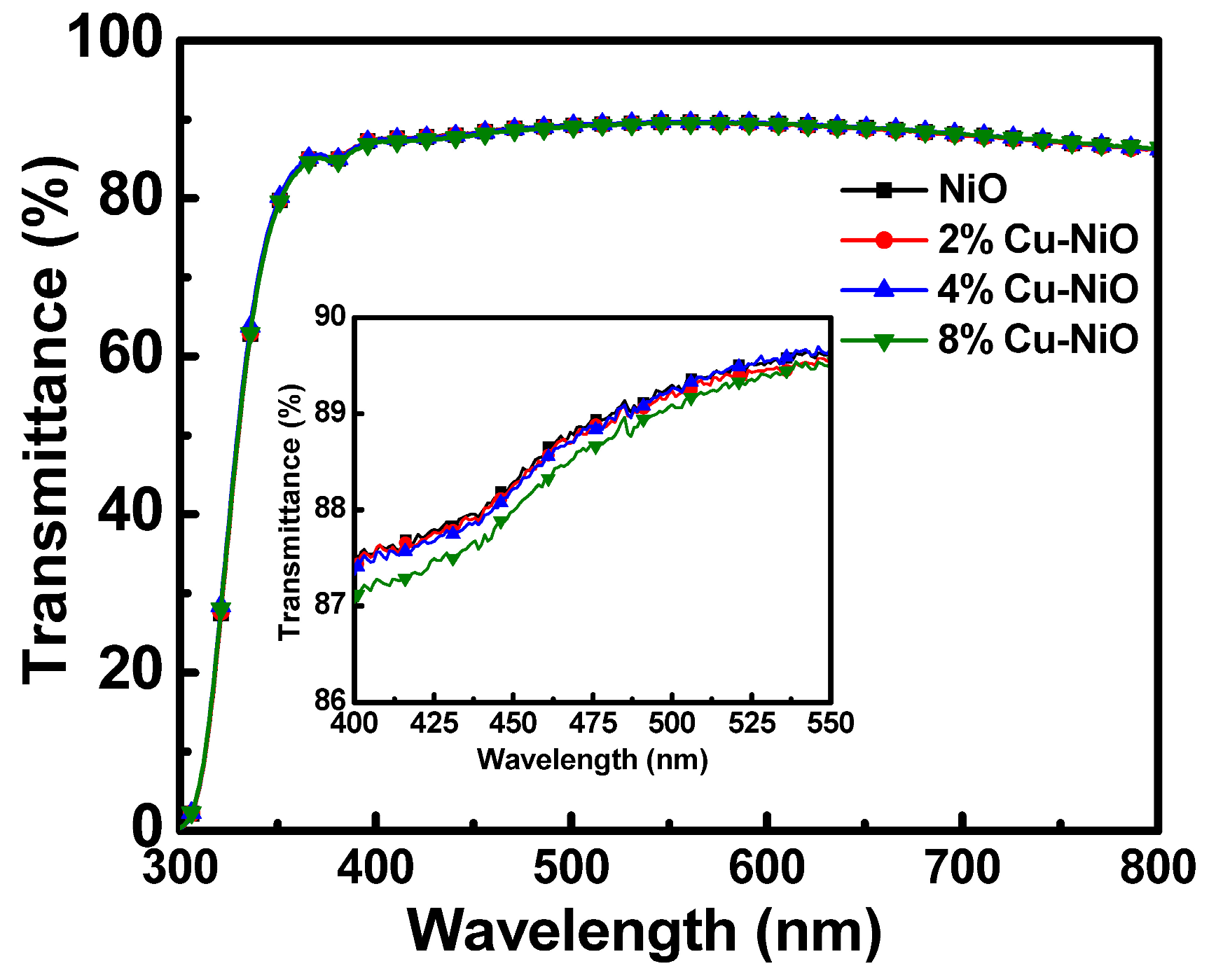
The optical properties were studied using UV-Vis spectroscopy. We measured the absorbance spectra of equally concentrated NiOx and Cu-NiOx NPs dispersed in DI water (Figure 4) in the wavelength range from 300 to 800 nm. The absorbance increased with an increase in the Cu concentration. The optical bandgaps were calculated using the standard Tauc plot method. The bandgap values were 3.8, 3.74, 3.71, and 3.66 eV for undoped NiOx, 2%, 4%, and 8% Cu-NiOx NPs, respectively. The bandgap values of synthesized NPs decreased with an increase in the Cu concentration. The incorporation of Cu atoms slightly narrowed the bandgap. The transmittance spectra of spin-coated NiOx and Cu-NiOx NPs on glass is illustrated in Figure 5, which revealed more than 85% of transmission in the visible region. The transmittance value decreased with an increase in the Cu concentration because of the narrowing bandgap.
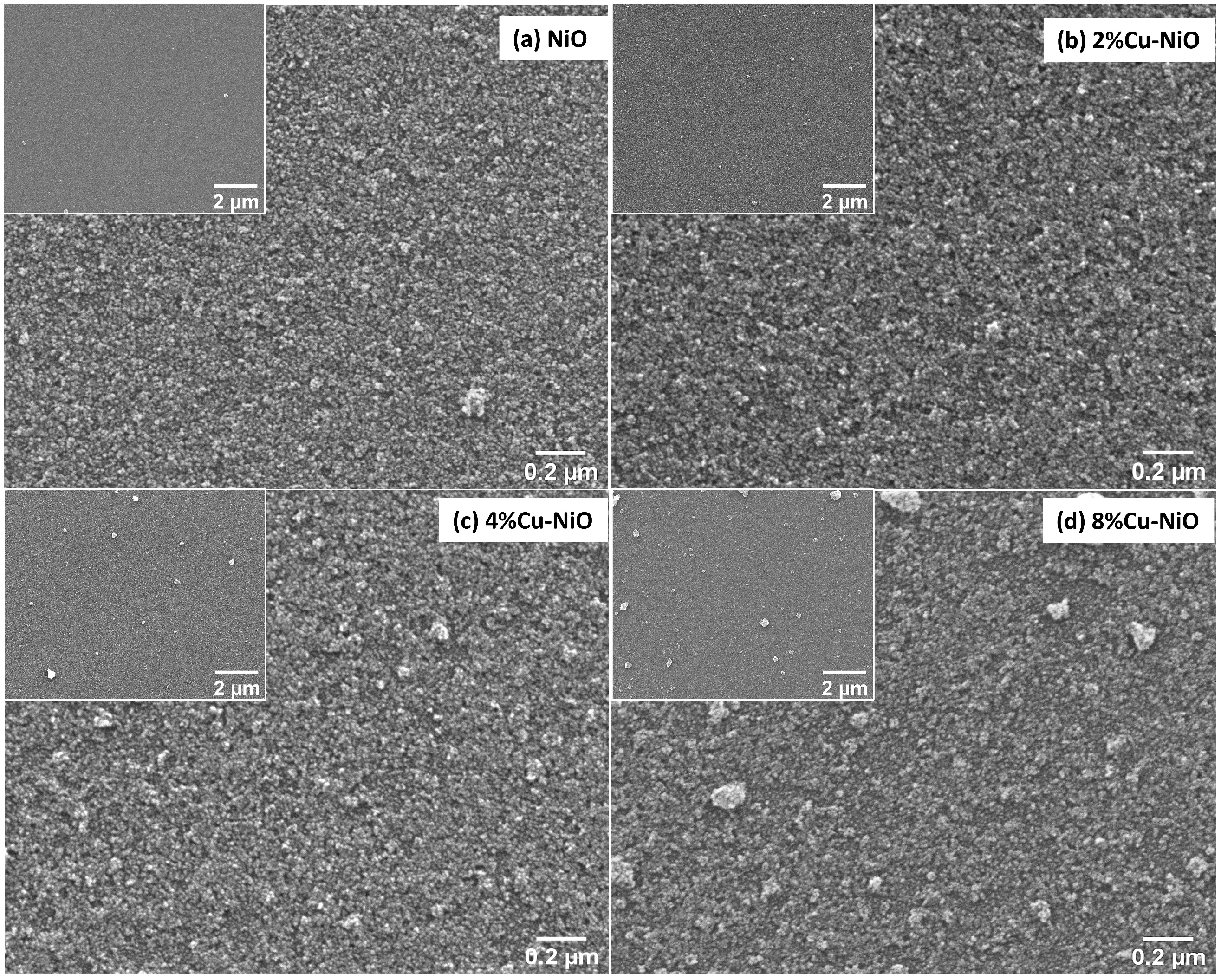
The surface morphologies of NiOx and various percentages of Cu-NiOx NPs were observed through FESEM. Figure 6 clearly reveals that the NPs completely covered the substrate, and no pinholes or voids occurred, which confirmed the presence of some nanoclusters in the 4% and 8% Cu-NiOx NP films. The size of the nanoclusters increased with an increase in the doping concentration of Cu. The conversion of Ni(OH)2 to NiOx occurred in the temperature range 250–305 °C, but the conversion of Cu(OH)2 to CuO occurred from 150 °C, which resulted in the formation of these small nanoclusters. So far, the formation of these clusters because of copper doping has not been reported. The FESEM images of NiOx and 2% Cu-NiOx were similar, and they almost completely dispersed in DI water. In similar studies, the thickness of the HTL was reported to be approximately 50 nm, which is typically sufficient to ensure uniform coverage and efficient charge transport without increasing series resistance [44]. Therefore, they were selected for device fabrication.
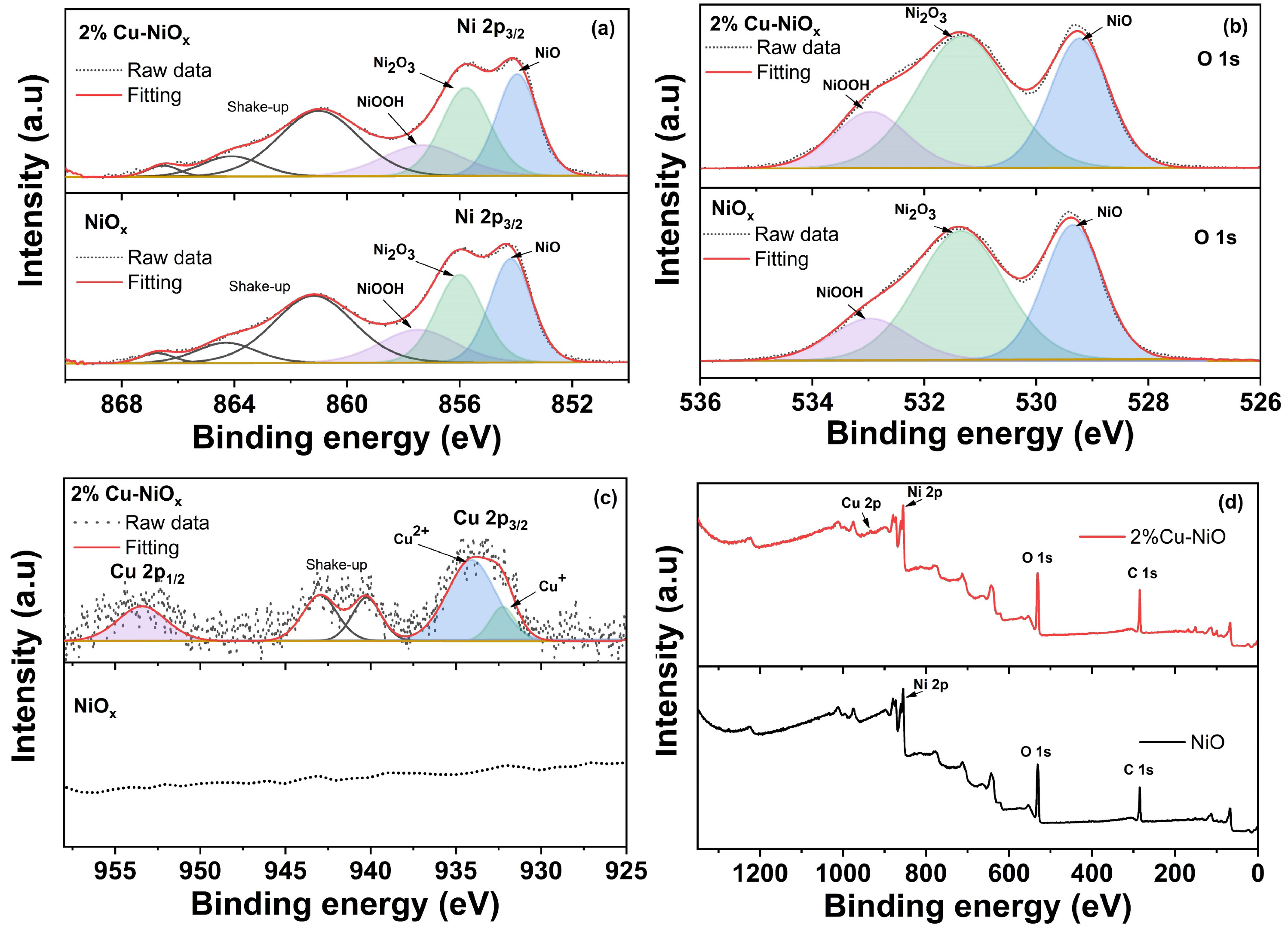
XPS was performed to examine the elemental composition of NiOx NPs and 2% Cu-NiOx films. The XPS spectra of the Ni 2p, O 1s, and Cu 2p core level are illustrated in Figure 7. The Ni 2p spectra consisted of two peaks, namely, the main peak and the shoulder peak. The deconvoluted peaks at 853, 856, and 858 eV corresponded to NiO (Ni2+), Ni2O3 (Ni3+), and NiOOH, respectively. The Ni3+ ions confirmed the presence of Ni vacancies in the film, which rendered the film a p-type semiconductor. The peak at 861 eV was attributed to the modification of the NiO structure [45,46]. There was no significant change in the Ni 2p peaks between the NiOx and Cu-NiOx thin films. The O 1s spectra exhibited three peaks at 529, 531, and 533 eV, which corresponded to NiO (Ni2+), Ni2O3 (Ni3+), and NiOOH ions, respectively. In Cu 2p spectra, the peaks located at 933 and 953 eV corresponded to Cu 2p3/2 and Cu 2p1/2 transitions, respectively. The Cu2+ peak was dominant in Cu 2p3/2 spectra, whereas the Cu+ peak was not significant [47]. The surface topography of NiOx and 2% Cu-NiOx NP thin films was investigated through AFM. Figure 8 displays the AFM images of NiOx and 2% Cu-NiOx NP thin films. The average root-mean-square roughness values of the NiOx and 2% Cu-NiOx NPs films were 4.068 ± 1.067 and 3.527 ± 0.9376 nm, respectively. The roughness decreased with Cu doping, which was consistent with reports.
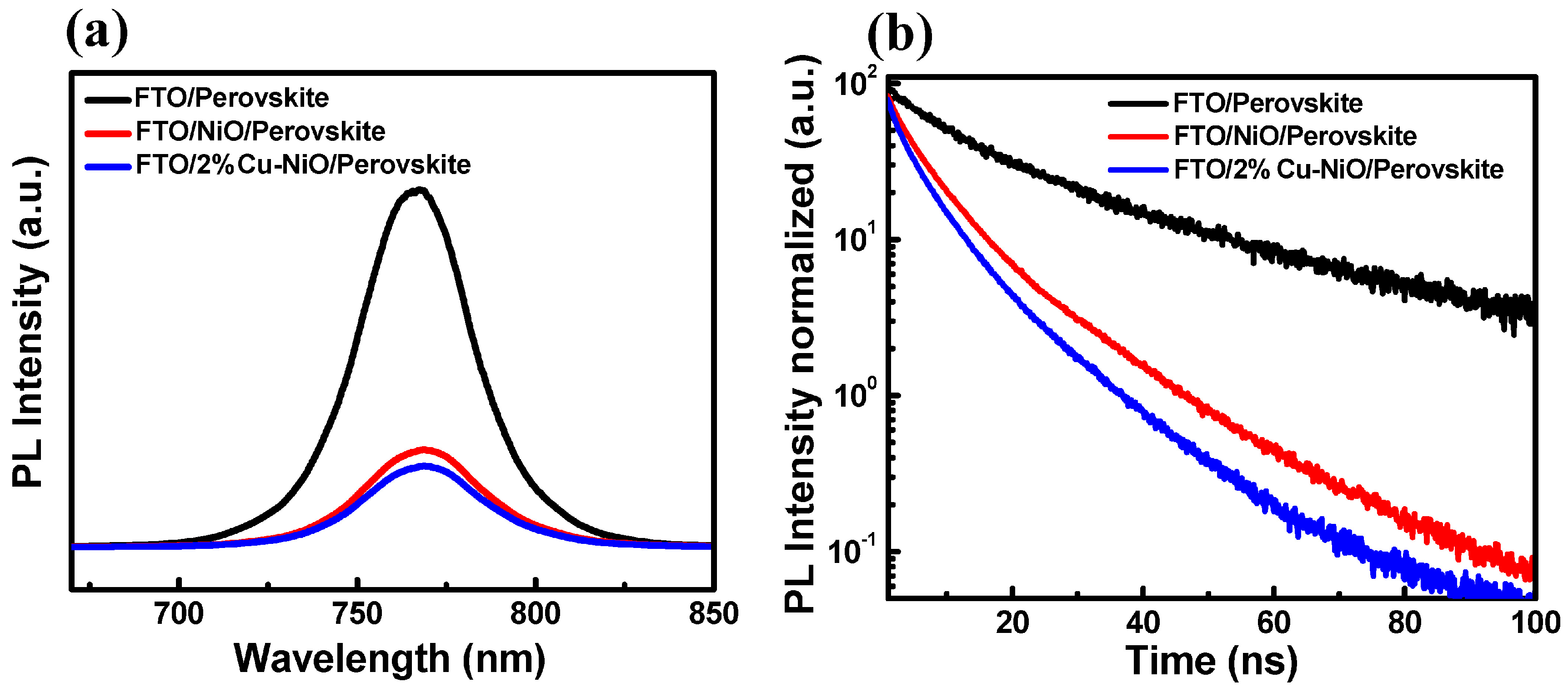
PL and time-resolved PL (TRPL) were used to evaluate charge extraction and recombination from the devices. Typically, PL quenching and a short PL lifetime are expected for perovskites in contact with charge transport layers. We measured the PL spectra and the TRPL profile of the perovskite layers deposited on various HTLs (Figure 9). The PL quenching was better for the perovskite film deposited on Cu-NiOx than for that on pristine NiOx, which indicated that Cu incorporation in NiOx improved the charge extraction property from the perovskite film. The TRPL profile was measured through time-correlated single-photon counting to analyze charge dynamics. PL lifetime decay tails were fitted with biexponential fitting function y = y 0 + A 1 e ( x x 0 ) / τ 1 + A 2 e ( x x 0 ) / τ 2 , where (τ1) is related to the diffusion of photogenerated excitons into defects, and (τ2) is related to intrinsic electron–hole recombination. The average PL lifetime value was calculated using the formula τ a v g = ( Σ i A i τ i 2 ) / ( Σ i A i τ i ) . The obtained fitting values are summarized in Table 2. The PL lifetime for the perovskite film deposited on Cu-NiOx was shorter than that of pristine NiOx, which indicates higher efficient charge transfer in Cu-NiOx.

3.3. Characterization of the PSC Devices

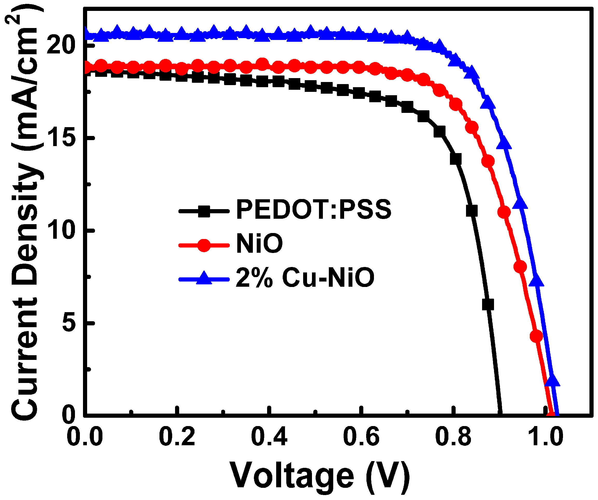
The J–V curve, EQE, and EIS analyses were performed to investigate the PSC device performance of the synthesized NiOx and 2% Cu-NiOx NP HTLs. The device structure of the inverted PSCs was Glass/FTO/NiOx or Cu-NiOx or PEDOT:PSS/perovskite/PCBM/BCP/Ag. We also fabricated PSCs with a PEDOT:PSS HTL for comparison. The J–V analysis was first performed on the devices to investigate the effects of Cu doping in NiOx NP HTLs on the short-circuit current density (JSC), open-circuit voltage (VOC), fill factor (FF), and PCE of the PSC device. The J–V curves of fabricated inverted PSCs with PEDOT:PSS, NiOx, and 2% Cu-NiOx HTLs are displayed in Figure 10. Both NiOx and 2% Cu-NiOx exhibited better performance than the PEDOT:PSS HTL devices. The detailed device parameters are listed in Table 3. The 2% Cu-NiOx device exhibited the highest JSC value of 20.57 mA/cm2, whereas the PEDOT:PSS and pristine NiOx devices exhibited JSC values of 18.83 and 18.66 mA/cm2, respectively. The JSC value was higher in the Cu-based device than that in the pristine NiOx device. This phenomenon was attributed to the increased electrical conductivity and better energy alignment of the HTL to the perovskite layer because of the incorporation of Cu in nickel oxide. The 2% Cu-NiOx device exhibited a VOC of 1.026, an FF of 0.74, and a PCE of 15.54%. The 2% Cu-NiOx NP-based device showed the best performance compared with the pristine NiOx and PEDOT:PSS devices.
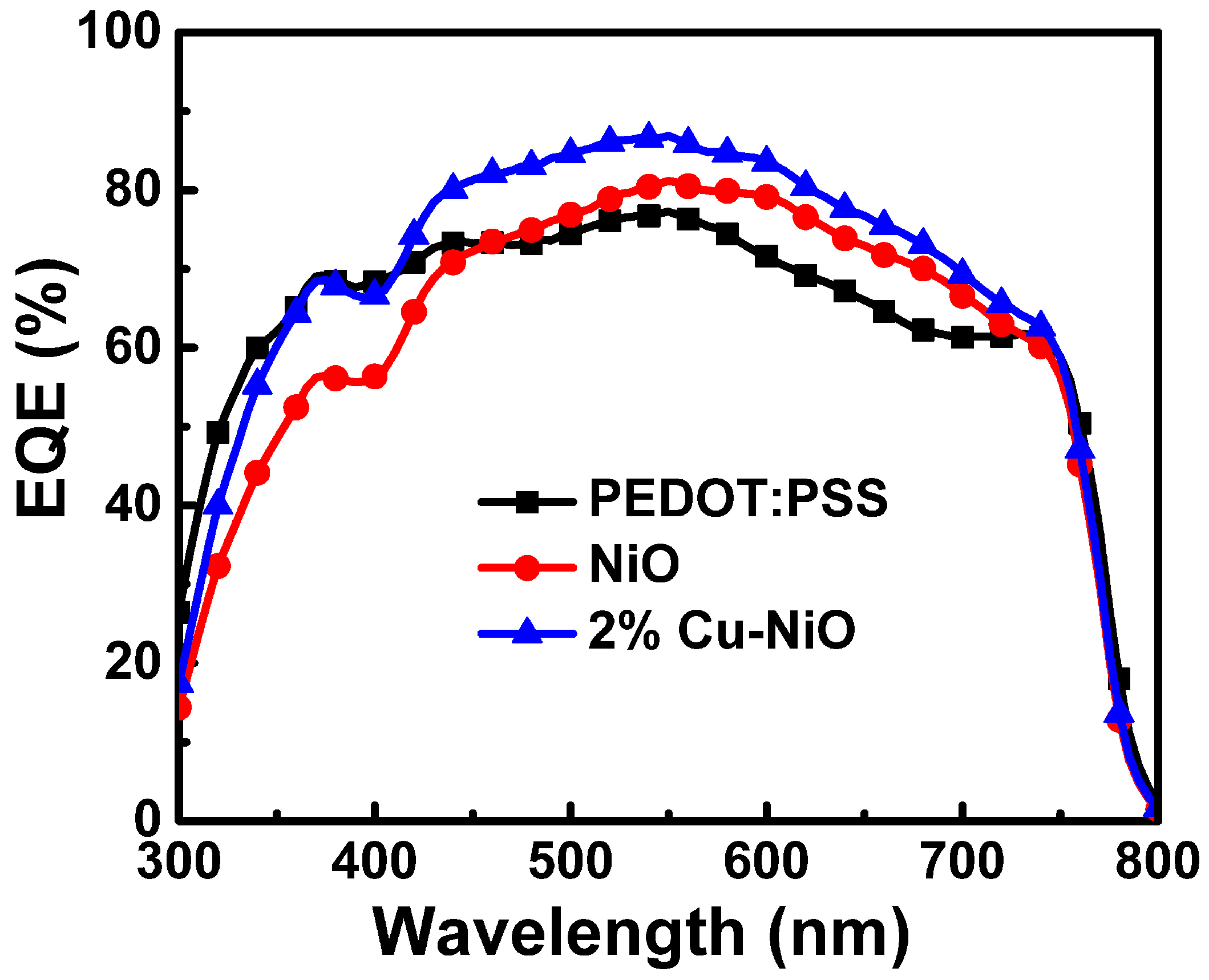
The EQE spectra of the PEDOT:PSS-, NiOx-, and 2% Cu-NiOx-based devices are displayed in Figure 11. The EQE spectra of NiOx and Cu-NiOx devices were similar, but the Cu-doped device exhibited a higher EQE value than the pristine NiOx device did. A slight difference in EQE spectra at higher wavelengths for the PEDOT:PSS device was observed. The fabricated devices exhibited satisfactory EQE values in the entire visible region. The higher EQE values in the Cu-doped device indicated that Cu-NiOx HTLs exhibited better charge transport properties.
The results of EIS performed on the fabricated devices are displayed in Figure 12. The Nyquist plot for the devices fabricated using PEDOT:PSS, NiOx, and 2% Cu-NiOx were analyzed in the frequency range from 10 Hz to 1 MHz, and the AC amplitude was 0.01 V under one solar illumination at a bias of VOC. Typically, the higher-frequency regime corresponded to the charge transport resistance of the MAPbI3/HTL interface and the lower-frequency regime was attributed to a low-frequency dielectric response of the perovskite materials [48,49]. A low impedance value is more favorable to carrier transport. The EIS results indicated that the Cu-NiOx devices exhibited the lowest impedance value. This result was consistent with the J–V and EQE results.
The Cu doping in NiOx increased the electrical conductivity, which reduced the charge transport resistance at the MAPbI3/HTL interface and enhanced the band alignment between perovskites and HTLs.

4. Conclusions

We fabricated inverted PSCs using NiOx and Cu-NiOx HTLs through spin-coating NP inks. The prepared spin-coated films were uniform and did not exhibit any voids. Cu incorporation into NiOx did not change its crystalline nature and considerably improved its electrical conductivity. The optical bandgap decreased with an increase in the Cu concentration. Few nanoclusters occurred at higher doping concentrations because of the differences in the calcination temperature between Ni(OH)2 and Cu(OH)2. The Cu-NiOx HTLs exhibited superior PL quenching and the least lifetime decay, which indicated that Cu-NiOx exhibited superior charge transport compared with pristine NiOx HTLs. The EQE in the Cu-doped device throughout the visible region was higher than that in other devices. EIS analysis revealed the incorporation of Cu in NiOx HTL reduced the interface impedance. The fabricated NiOx and 2% Cu-NiOx PSCs exhibited PCEs of 13.72% and 15.54%, respectively.

Author Contributions

Conceptualization, C.-H.T. and P.S.T.; methodology, C.-H.T., P.S.T. and C.-C.L.; validation, C.-H.T.; formal analysis, C.-H.T., P.S.T. and C.-C.L.; investigation, C.-H.T., P.S.T. and C.-C.L.; resources, C.-H.T.; data curation, C.-H.T., P.S.T. and C.-C.L.; writing—original draft preparation, C.-H.T. and P.S.T.; writing—review and editing, C.-H.T. and P.S.T.; supervision, C.-H.T.; project administration, C.-H.T.; funding acquisition, C.-H.T. All authors have read and agreed to the published version of the manuscript.

Funding

This research was funded by Ministry of Science and Technology (MOST) of Taiwan (grant No. MOST 108-2221-E-259-011).

Institutional Review Board Statement

Not applicable.

Informed Consent Statement

Not applicable.

Data Availability Statement

The data in this work are available on request from the corresponding author.

Conflicts of Interest

The authors declare no conflicts of interest.

References

  1. Masri, M.; B, G.K.; Hezam, A.; Alkanad, K.; Prashantha, K.; Manjunath, S.H.; Udayabhanu; Masri, F.; Qahtan, T.F.; Byrappa, K. Metal Halide Perovskite-Based Photocatalysts for Organic Pollutants Degradation: Advances, Challenges, and Future Directions. Colloids Surf. A Physicochem. Eng. Asp. 2024, 687, 133387. [Google Scholar] [CrossRef]
  2. Juhi, J.; Saski, M.; Kochaniec, M.K.; Wieczorek, W.; Dominko, R.; Lewiński, J. Exploring Metal Halide Perovskites as Active Architectures in Energy Storage Systems. J. Mater. Chem. A 2025. [Google Scholar] [CrossRef]
  3. Shooshtari, M.; Kim, S.-Y.; Pahlavan, S.; Rivera-Sierra, G.; Través, M.J.; Serrano-Gotarredona, T.; Bisquert, J.; Linares-Barranco, B. Advancing Logic Circuits with Halide Perovskite Memristors for Next-Generation Digital Systems. SmartMat 2025, 6, e70032. [Google Scholar] [CrossRef]
  4. Afre, R.A.; Pugliese, D. Perovskite Solar Cells: A Review of the Latest Advances in Materials, Fabrication Techniques, and Stability Enhancement Strategies. Micromachines 2024, 15, 192. [Google Scholar] [CrossRef]
  5. Liu, J.; Li, S.; Mei, A.; Han, H. Applications of Metal Oxide Charge Transport Layers in Perovskite Solar Cells. Small Sci. 2023, 3, 2300020. [Google Scholar] [CrossRef]
  6. Wu, Y.-W.; Wang, C.-Y.; Yang, S.-H. Exploration and Optimization of the Polymer-Modified NiOx Hole Transport Layer for Fabricating Inverted Perovskite Solar Cells. Nanomaterials 2024, 14, 1054. [Google Scholar] [CrossRef]
  7. Jeng, J.Y.; Chen, K.C.; Chiang, T.Y.; Lin, P.Y.; Tsai, T.D.; Chang, Y.C.; Guo, T.F.; Chen, P.; Wen, T.C.; Hsu, Y.J. Nickel Oxide Electrode Interlayer in CH3NH3PbI3 Perovskite/PCBM Planar-Heterojunction Hybrid Solar Cells. Adv. Mater. 2014, 26, 4107–4113. [Google Scholar] [CrossRef]
  8. Alghamdi, A.R.M.; Yanagida, M.; Shirai, Y.; Andersson, G.G.; Miyano, K. Surface Passivation of Sputtered NiOx Using a SAM Interface Layer to Enhance the Performance of Perovskite Solar Cells. ACS Omega 2022, 7, 12147–12157. [Google Scholar] [CrossRef]
  9. Zhu, K.; Chen, Y.; Wang, Y.; Feng, M.; Zhao, Y. Progress of Solution-Processed Metal Oxides as Charge Transport Layers towards Efficient and Stable Perovskite Solar Cells and Modules. Mater. Today Nano 2022, 20, 100252. [Google Scholar] [CrossRef]
  10. Aristizábal-Duarte, L.; González-Hernández, M.; Reyes, S.E.; Ramírez-Rincón, J.A.; Ortiz, P.; Cortés, M.T. Enhanced Charge Transport in Inverted Perovskite Solar Cells via Electrodeposited La-Modified NiOx Layers. Energies 2025, 18, 3590. [Google Scholar] [CrossRef]
  11. Yuk, D.; Roe, J.; Lee, Y.; Kim, J.; Seo, J.; Yeop, J.; Song, T.; Kim, J.Y. Improving the Optoelectrical Properties of a Nickel Oxide Hole Transport Layer by Hydrogen Peroxide Treatment for Efficient Organic Solar Cells. ACS Appl. Energy Mater. 2024, 7, 4558–4564. [Google Scholar] [CrossRef]
  12. Tang, G.; Chen, L.; Cao, X.; Wang, Y.; Zhang, H.; Tai, Q. A Review on Recent Advances in Flexible Perovskite Solar Cells. Sol. RRL 2025, 9, 2400844. [Google Scholar] [CrossRef]
  13. Chang, C.-Y.; Wu, Y.-W.; Yang, S.-H.; Abdulhalim, I. Preparation of Nickel Oxide Nanoflakes for Carrier Extraction and Transport in Perovskite Solar Cells. Nanomaterials 2022, 12, 3336. [Google Scholar] [CrossRef] [PubMed]
  14. Reyes, S.E.; González-Hernández, M.; Cortés, M.T.; Ortiz, P. Effect of NH4F Surface Treatment of Electrodeposited NiOx on the Properties and Reproducibility of Inverted Perovskite Solar Cells. Surf. Interfaces 2025, 56, 105654. [Google Scholar] [CrossRef]
  15. Lin, Y.; Zhang, X.; Zhong, X.; Lu, C.; Lu, Y.; Li, X.; Tu, S. Construction of Novel D-A Type Self-Assembled Molecules Together with NiOx for Flexible Perovskite Solar Cells. Tetrahedron 2025, 176, 134541. [Google Scholar] [CrossRef]
  16. Noman, M.; Khan, Z.; Jan, S.T. A Comprehensive Review on the Advancements and Challenges in Perovskite Solar Cell Technology. RSC Adv. 2024, 14, 5085–5131. [Google Scholar] [CrossRef]
  17. Tutundzic, M.; Zhang, X.; Lammar, S.; Singh, S.; Marchezi, P.; Merckx, T.; Aguirre, A.; Moons, E.; Aernouts, T.; Kuang, Y.; et al. Toward Efficient and Fully Scalable Sputtered NiOx-Based Inverted Perovskite Solar Modules via Co-Ordinated Modification Strategies. Sol. RRL 2023, 8, 2300862. [Google Scholar] [CrossRef]
  18. Kim, J.W.; Cho, E.; Lee, H.; Kwon, S.; Park, J.; Kim, M.; Kim, D.; Na, S.; Lee, S. Enhancing Efficiency of Inverted Perovskite Solar Cells by Sputtered Nickel Oxide Hole Transport Layers. Sol. RRL 2023, 8, 2300933. [Google Scholar] [CrossRef]
  19. Yadav, K.; Samanta, A.; Ankita; Tarun; Das, S.; Kanjilal, A.; Pandey, U.K. Tailoring Sputter Grown NiOx Layer by Synergistic Surface Passivation for Efficient Perovskite Solar Cells. Sol. Energy 2025, 288, 113286. [Google Scholar] [CrossRef]
  20. Feng, M.; Wang, Y.; Liu, F.; Ren, M.; Wang, H.; Guo, J.; Chen, Y.; Miao, Y.; Zhao, Y. Rational Buried Interface Engineering of Inorganic NiOx Layer toward Efficient Inverted Perovskite Solar Cells. Sol. RRL 2023, 8, 2300712. [Google Scholar] [CrossRef]
  21. Lu, X.; Fan, X.; Zhang, H.; Xu, Q.; Ijaz, M. Review on Preparation of Perovskite Solar Cells by Pulsed Laser Deposition. Inorganics 2024, 12, 128. [Google Scholar] [CrossRef]
  22. Akalin, S.A.; Erol, M.; Uzunbayir, B.; Oguzlar, S.; Yildirim, S.; Choi, F.P.G.; Gunes, S.; Menda, U.D.Y.; Mendes, M.J. Physically-Deposited Hole Transporters in Perovskite PV: NiOx Improved with Li/Mg Doping. Adv. Mater. Technol. 2024, 9, 2301760. [Google Scholar] [CrossRef]
  23. Jiang, Q.; Zhu, K. Rapid Advances Enabling High-Performance Inverted Perovskite Solar Cells. Nat. Rev. Mater. 2024, 9, 399–419. [Google Scholar] [CrossRef]
  24. Mann, D.S.; Kwon, S.-N.; Patil, P.; Na, S.-I. Revivification of Nickel Oxide-Perovskite Interfaces via Nickel Nitrate to Boost Performance in Perovskite Solar Cells. Nano Energy 2022, 106, 108062. [Google Scholar] [CrossRef]
  25. Song, D.; Shin, S.W.; Wu, H.-P.; Diau, E.W.-G.; Correa-Baena, J.P. Toward Maximizing Hole Selection with Self-Assembled Monolayers in Sn-Based Perovskite Solar Cells. ACS Energy Lett. 2025, 10, 1292–1312. [Google Scholar] [CrossRef]
  26. Soopy, A.K.K.; Parida, B.; Aravindh, S.A.; Al Ghaithi, A.O.; Qamhieh, N.; Amrane, N.; Benkraouda, M.; Liu, S.; Najar, A. Towards High Performance: Solution-Processed Perovskite Solar Cells with Cu-Doped CH3NH3PbI3. Nanomaterials 2024, 14, 172. [Google Scholar] [CrossRef]
  27. Verma, A.P.; Yadav, P.; Nalwa, K.S.; Kumar, M. Interface Engineering and Band Alignment Studies of Cu Doped NiO as a Hole Transport Layer for Triple Cationic Perovskite Solar Cells. Small 2025, 21, 2504237. [Google Scholar] [CrossRef]
  28. Jin, Y.; Feng, H.; Li, Y.; Zhang, H.; Chen, X.; Zhong, Y.; Zeng, Q.; Huang, J.; Weng, Y.; Yang, J.; et al. Recrystallizing Sputtered NiOx for Improved Hole Extraction in Perovskite/Silicon Tandem Solar Cells. Adv. Energy Mater. 2024, 15, 2403911. [Google Scholar] [CrossRef]
  29. Yu, S.; Xiong, Z.; Zhou, H.; Zhang, Q.; Wang, Z.; Ma, F.; Qu, Z.; Zhao, Y.; Chu, X.; Zhang, X.; et al. Homogenized NiOx Nanoparticles for Improved Hole Transport in Inverted Perovskite Solar Cells. Science 2023, 382, 1399–1404. [Google Scholar] [CrossRef]
  30. Wang, L.; Li, Y.; Shen, H.; Wang, L.; Zhao, Q.; Zheng, J.; Li, H.; Xie, Z.; Chen, A.; Miao, S.; et al. Highly Stable Inverted Perovskite Solar Cells with All-Inorganic Selective Contact Using Iron-Doped Zinc Oxide. J. Chem. Phys. 2025, 162, 094703. [Google Scholar] [CrossRef]
  31. Li, M.; Zhang, Z.; Sun, J.; Liu, F.; Chen, J.; Ding, L.; Chen, C. Perovskite Solar Cells with NiOx Hole-Transport Layer. J. Semicond. 2023, 44, 100201. [Google Scholar] [CrossRef]
  32. Valenzuela-López, J.Y.; Millán-Franco, M.A.; Suárez-Campos, G.; Camacho-Cáceres, J.; Rodríguez-Castañeda, C.A.; Moreno-Romero, P.M.; Torres-Herrera, D.M.; Sotelo-Lerma, M.; Hu, H. Influence of Nickel Precursor Solutions on Nickel Oxide Thin Film Formation and Photovoltaic Properties of Air-Processed Inverted Perovskite Solar Cells. Opt. Mater. 2024, 149, 115082. [Google Scholar] [CrossRef]
  33. Madani, S.; Tesfamichael, T.; Wang, H.; Motta, N. Study of Pb-Based and Pb-Free Perovskite Solar Cells Using Cu-Doped Ni1-XO Thin Films as Hole Transport Material. Ceram. Int. 2022, 48, 15207–15217. [Google Scholar] [CrossRef]
  34. Liu, S.; Biju, V.P.; Qi, Y.; Chen, W.; Liu, Z. Recent Progress in the Development of High-Efficiency Inverted Perovskite Solar Cells. NPG Asia Mater. 2023, 15, 27. [Google Scholar] [CrossRef]
  35. Luo, X.; Liu, X.; Lin, X.; Wu, T.; Wang, Y.; Han, Q.; Wu, Y.; Segawa, H.; Han, L. Recent Advances of Inverted Perovskite Solar Cells. ACS Energy Lett. 2024, 9, 1487–1506. [Google Scholar] [CrossRef]
  36. Andrade, P.H.M.; Volkringer, C.; Loiseau, T.; Tejeda, A.; Hureau, M.; Moissette, A. Band Gap Analysis in MOF Materials: Distinguishing Direct and Indirect Transitions Using UV–Vis Spectroscopy. Appl. Mater. Today 2024, 37, 102094. [Google Scholar] [CrossRef]
  37. Barkaoui, S.; Wang, Y.; Zhang, Y.; Gu, X.; Li, Z.; Wang, B.; Baiker, A.; Li, G.; Zhao, Z. Critical Role of NiO Support Morphology for High Activity of Au/NiO Nanocatalysts in CO Oxidation. iScience 2024, 27, 110255. [Google Scholar] [CrossRef]
  38. de Souza Caldas, L.; Prieto, M.J.; Tănase, L.C.; Tiwari, A.; Schmidt, T.; Cuenya, B.R. Correlative in Situ Spectro-Microscopy of Supported Single CuO Nanoparticles: Unveiling the Relationships between Morphology and Chemical State during Thermal Reduction. ACS Nano 2024, 18, 13714–13725. [Google Scholar] [CrossRef]
  39. Baraneedharan, P.; Sekar, S.; Murugesan, S.; Ahamada, D.; Mohamed, S.A.B.; Lee, Y.; Lee, S. Recent Advances and Remaining Challenges in Perovskite Solar Cell Components for Innovative Photovoltaics. Nanomaterials 2024, 14, 1867. [Google Scholar] [CrossRef]
  40. Zhang, W.; Shen, H.; Zhang, J.; Zhang, J.; Lu, L.; Zhu, X.; Li, D. NiOx Thickness Dependent Improvement of NiOx/Perovskite Interface for Inverted Planar Perovskite Solar Cells. Opt. Mater. 2022, 132, 112774. [Google Scholar] [CrossRef]
  41. Chen, P.; Xiao, Y.; Li, S.; Jia, X.; Luo, D.; Zhang, W.; Snaith, H.J.; Gong, Q.; Zhu, R. The Promise and Challenges of Inverted Perovskite Solar Cells. Chem. Rev. 2024, 124, 10623–10700. [Google Scholar] [CrossRef]
  42. Ye, Z.; Xia, J.; Zhang, D.; Duan, X.; Xing, Z.; Jin, G.; Cai, Y.; Xing, G.; Chen, J.; Ma, D. Efficient Quasi-2D Perovskite Light-Emitting Diodes Enabled by Regulating Phase Distribution with a Fluorinated Organic Cation. Nanomaterials 2022, 12, 3495. [Google Scholar] [CrossRef]
  43. Miah, M.H.; Khandaker, M.U.; Aminul Islam, M.; Nur-E-Alam, M.; Osman, H.; Ullah, M.H. Perovskite Materials in X-Ray Detection and Imaging: Recent Progress, Challenges, and Future Prospects. RSC Adv. 2024, 14, 6656–6698. [Google Scholar] [CrossRef]
  44. Chen, W.; Wu, Y.; Fan, J.; Djurišić, A.B.; Liu, F.; Tam, H.W.; Ng, A.; Surya, C.; Chan, W.K.; Wang, D.; et al. Understanding the Doping Effect on NiO: Toward High-Performance Inverted Perovskite Solar Cells. Adv. Energy Mater. 2018, 8, 1703519. [Google Scholar] [CrossRef]
  45. Nyiekaa, E.A.; Aika, T.A.; Orukpe, P.E.; Akhabue, C.E.; Danladi, E. Development on Inverted Perovskite Solar Cells: A Review. Heliyon 2024, 10, e24689. [Google Scholar] [CrossRef] [PubMed]
  46. Diethelm, M.; Lukas, T.; Smith, J.; Dasgupta, A.; Caprioglio, P.; Futscher, M.; Hany, R.; Snaith, H.J. Probing Ionic Conductivity and Electric Field Screening in Perovskite Solar Cells: A Novel Exploration through Ion Drift Currents. Energy Environ. Sci. 2025, 18, 1385–1397. [Google Scholar] [CrossRef] [PubMed]
  47. Aliyaselvam, O.V.; Mustafa, A.N.; Azam, M.A.; Chelvanathan, P.; Islam, M.A.; Mahalingam, S.; Arith, F. Unveiling the Prospect of Copper Iodide as Hole Transporting Layer in Perovskite Solar Cell by Selective Dopant Strategy: A Review. Mater. Sci. Semicond. Process. 2025, 197, 109679. [Google Scholar] [CrossRef]
  48. Chin, Y.-C.; Daboczi, M.; Henderson, C.; Luke, J.; Kim, J.-S. Suppressing PEDOT:PSS Doping-Induced Interfacial Recombination Loss in Perovskite Solar Cells. ACS Energy Lett. 2022, 7, 560–568. [Google Scholar] [CrossRef]
  49. Qu, J.; Zhang, W.; Chen, Y.; Zhao, H.; Wei, Y.; Zhou, R.; Wan, H.; Deng, J.; Fan, D.; Luo, Y.; et al. Multifunctional Amine Salt Additive for Enhancing the Performance of Perovskite and Perovskite/Silicon Tandem Solar Cells. Chem. Eng. J. 2025, 515, 163967. [Google Scholar] [CrossRef]
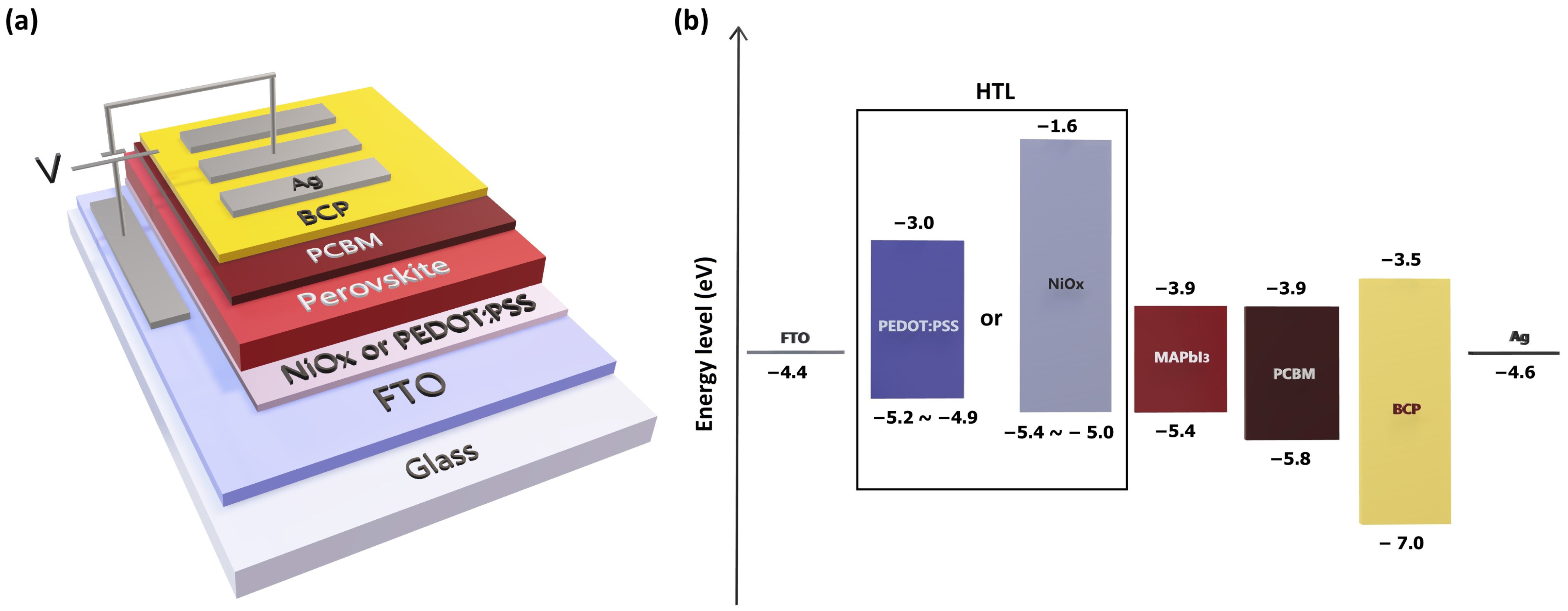
Figure 1. (a) Device structure and (b) energy level diagram of fabricated inverted PSCs.
Applsci 15 11449 g001
Figure 2. Schematic diagram of device fabrication.
Applsci 15 11449 g002
Figure 3. XRD patterns of the NiOx and various concentration of Cu-NiOx nanoparticles.
Applsci 15 11449 g003
Figure 4. The optical bandgap, absorbance spectra, and photograph of NiOx and various concentration of Cu-NiOx nanoparticles.
Applsci 15 11449 g004
Figure 5. Transmittance spectra of NiOx and various concentration of Cu-NiOx spin-coated thin films.
Applsci 15 11449 g005
Figure 6. FESEM images of (a) NiOx, (b) 2%, (c) 4%, and (d) 8% Cu-NiOx spin-coated thin films.
Applsci 15 11449 g006
Figure 7. XPS spectra of (a) Ni 2p, (b) O 1s, (c) Cu 2p, and (d) survey scan for NiOx and 2% Cu-NiOx thin films.
Applsci 15 11449 g007
Figure 8. AFM images of (a) NiOx and (b) 2% Cu-NiOx thin films.
Applsci 15 11449 g008
Figure 9. (a) Photoluminescence spectra and (b) time-resolved PL spectra for perovskite films on different HTLs.
Applsci 15 11449 g009
Figure 10. J-V characteristics of the devices made of PEDOT:PSS, NiOx, and Cu-NiOx as HTLs.
Applsci 15 11449 g010
Figure 11. EQE of the devices made of PEDOT:PSS, NiOx, and Cu-NiOx as HTLs.
Applsci 15 11449 g011
Figure 12. EIS of the devices made of PEDOT:PSS, NiOx, and Cu-NiOx as HTLs.
Applsci 15 11449 g012
Table 1. Microstructural properties of NiOx and Cu-NiOx nanoparticles.
Sample(hkl)Interplanar Distance (Å)FWHM (β)
(radians)
Crystallite Size (D) (nm)Dislocation Density (1/D2)
(×1016)
Microstrain (β/4tanθ)Lattice
Parameter
(a)
NiOx37(111)2.430.034.944.121.274.21
43.09(002)2.10.044.734.491.154.2
62.54(022)1.490.044.524.920.854.21
2% Cu-NiOx37.09(111)2.430.036.512.370.964.2
43.16(002)2.10.035.673.130.964.2
62.59(022)1.490.036.252.570.624.2
4% Cu-NiOx36.96(111)2.440.034.914.171.284.22
43.07(002)2.110.044.215.651.294.21
62.55(022)1.490.044.066.070.954.2
8% Cu-NiOx36.96(111)2.440.044.534.881.394.22
43.11(002)2.10.044.285.491.274.2
62.57(022)1.490.053.986.340.974.2
ICDD
98-000-5229
37.25(111)2.42
43.28(002)2.09
62.86(022)1.48
Table 2. Summary of the PL lifetime parameters from the fitting curves of the PL decay.
SampleA1 (%)τ1 (ns)A2 (%)τ2 (ns)τavg (ns)
FTO/PSK61.89.638.237.629.4
FTO/NiOx/PSK64.93.335.111.48.6
FTO/2% Cu-NiOx/PSK55.92.244.18.67.0
Table 3. Device performance of PEDOT:PSS, NiOx, and Cu-NiOx HTL PSCs (the average values were calculated from 12 devices for each HTL material).
HTLVOC (V)JSC (mA/cm2)Fill FactorPCE (%)
PEDOT:PSSAverage0.900 ± 0.02017.919 ± 0.8630.697 ± 0.01511.239 ± 0.464
Best0.90318.660.7111.93
NiOAverage1.015 ± 0.01919.014 ± 0.4560.702 ± 0.01113.539 ± 0.239
Best1.01518.830.7113.72
2% Cu-NiOAverage1.028 ± 0.00320.172 ± 0.2730.744 ± 0.00515.417 ± 0.118
Best1.02620.570.7415.54
Disclaimer/Publisher’s Note: The statements, opinions and data contained in all publications are solely those of the individual author(s) and contributor(s) and not of MDPI and/or the editor(s). MDPI and/or the editor(s) disclaim responsibility for any injury to people or property resulting from any ideas, methods, instructions or products referred to in the content.