Abstract
Modern machining industries require high precision and efficiency in machine tools, where thermal deformations significantly impact accuracy. This study focuses on optimizing the structural parameters of a vertical turning center to minimize thermal displacements affecting machining precision. The optimization process is divided into parametric and topological methodologies. The parametric approach targets three primary objectives: minimizing mass (q1), maximizing static stiffness (q2), and reducing thermal displacement (q3). Multi-criteria optimization techniques, including Pareto-based and scalarization methods, are applied to balance these conflicting factors. Finite Element Analysis (FEA) models assist in evaluating machine stiffness and displacement, with constraints imposed on structural mass and stiffness to maintain performance. Parametric optimization, using iterative computational algorithms such as Genetic Algorithm (GA) and Particle Swarm Optimization (PSO), refines rib and wall thicknesses of the lathe table to achieve displacement reductions. The optimization process successfully lowers displacement at critical measurement points while maintaining structural integrity. Hybrid PSO (hPSO) outperforms other algorithms in achieving optimal parameter sets with minimal computational effort. Topological optimization, based on the Solid Isotropic Microstructure with Penalization (SIMP) method, further enhances structural efficiency by refining material distribution. The iterative process identifies optimal energy flow paths while ensuring compliance with mechanical constraints. A hybrid approach integrating parametric adjustments with topological refinement leads to superior performance, achieving a 43% reduction in displacement at key measurement points compared to the initial design. The final optimized design reduces mass by 1 ton compared to the original model and 2.5 tons compared to the best rib–wall optimization results. The study’s findings establish a foundation for implementing active deformation compensation systems in machine tools, enhancing machining precision. The integration of parametric and topological optimization presents a robust framework for designing machine tool structures with improved thermal stability and structural efficiency.
1. Introduction
Modern industry demands that machine tools become increasingly efficient and precise. This article addresses one of the key errors affecting machining accuracy—errors caused by thermal deformations of the machine tool’s supporting structure. It is estimated that this error can account for up to 70% of the total machining error [1], and its reduction or elimination can significantly improve machining accuracy.
Literature sources [2,3,4] provide an extensive discussion on the impact of heat generated by machine tool components on the dimensional and shape accuracy of manufactured parts. By limiting excessive heating of the machine tool assemblies, thermal deformation of components is reduced, which significantly improves machining precision. The phenomenon of minimizing heat influence on the machining process and its quality is especially important in the case of heavy-duty machine tools.
Therefore, to meet the stringent requirements for dimensional and shape accuracy, it is not sufficient to conduct only static, dynamic, and strength analyses of the machine tool. It is also essential to account for thermal deformations. Thermal analysis requires consideration of the distribution and influence of all heat sources, the material properties of structural elements and joints, as well as heat exchange with the environment.
Machine tools contain a considerable number of heat sources, both internal and external, whose heat generation intensity depends on load, operating time, and working conditions. The instability of generated heat leads to variability in the temperature distribution across machine tool components. Heat is generated during cutting processes, by drive motors (as thermal losses), and through friction in gears and guideways. External heat sources also significantly affect the heat distribution in the machine tool, transferring heat through convection and thermal radiation. These external sources include, among others, other nearby machine tools, heaters, sunlight, and fluids in contact with the machine (e.g., cutting fluids) [5,6,7].
One of the most commonly applied and described groups of methods for minimizing thermal deformations involves compensating for these deformations through CNC control of the machine tool. Such methods typically consist of three stages: measuring the temperature and thermal errors of the machine tool under typical operating conditions, establishing mathematical models correlating the temperature of machine components with the magnitude of errors, and compensating for thermal errors based on these models [8,9,10]. These methods often require the machine tool’s structure and the placement of heat sources to be as symmetrical as possible [11]. Achieving structural symmetry is challenging but feasible, whereas attaining symmetry in heat sources is often impractical. The objective of the research presented in this study was to develop reliable methods for optimizing the structural design of the rotary table of a vertical turning lathe, and more broadly, the design of machine tool body structures, with the aim of minimizing thermal deformations while maintaining the original level of static stiffness.
2. Research Subject
The research was conducted on a Rafamet S.A. KCI 600/800N vertical turning center, a heavy-duty machine tool designed for complex machining operations (Figure 1).
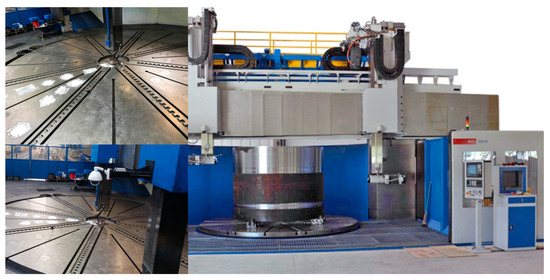
Figure 1.
Tested vertical turning center.
This lathe family is capable of turning cylindrical, conical, and curved surfaces, as well as machining components with intricate geometries. It supports turning, drilling, threading, and helical groove machining, making it highly versatile for industrial applications. The base and table bodies of the machine are cast from gray cast iron EN-GJL-250, ensuring structural stability. The base and table consist of three mechanically connected segments—one central and two side sections. The table is mounted axially and radially on roller bearings, with an adjustable clearance/preload mechanism to optimize performance. The table drive system includes two AC-powered motors (110 kW each), two spindles, and two gear wheels connected to a ring gear. Gear lubrication is provided by an oil-based closed system, ensuring efficient operation. Additionally, the control system continuously monitors lubrication pressure, oil flow, oil temperature, and the temperature of the main gear nodes to maintain optimal working conditions. In its current configuration, the maximum rotational speed of the table is 60 rpm, with a recommended long-term operational speed of 50 rpm for durability. Table 1 presents the key technical specifications of the machine, while Figure 2 provides a schematic representation of its construction and dimensional parameters.

Table 1.
Technical characteristics of the KCI 600/800N vertical lathe.
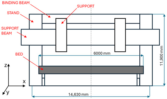
Figure 2.
Diagram of the construction of the KCI 600/800N vertical lathe and its characteristic parameters.
3. Optimization
The analyzed problem of machine tool body deformations can be considered within the framework of multi-criteria optimization. In general, optimization involves modifying three key parameters:
- q1(x)—Mass
- q2(x)—Static stiffness of the machine tool
- q3(x)—Thermal displacement
Thus, the problem can be formulated as a search for an optimal vector of decision variables that balances these conflicting objectives. There are several approaches to solving multi-criteria optimization problems, including
- Scalarization, where the multi-objective problem is transformed into a single-objective function by assigning weights to different criteria.
- Pareto-based optimization, which seeks a set of non-dominated solutions, allowing a trade-off between conflicting objectives without reducing them to a single metric.
Defining the primary and dominant criterion, as well as assessing the significance of the remaining criteria, allows for the transformation of a multi-criteria problem into a single-criterion problem according to the simplified scheme (Figure 3).
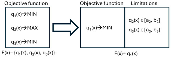
Figure 3.
Scheme of transformation of a multi-criteria task into a single-criteria task.
Before optimization can be performed, a certain number of computational analyses must be conducted. Finite element analysis (FEA) for complex models is highly time-consuming. To reduce computation time, certain simplifications are introduced. The primary simplification involves eliminating contact elements necessary for determining contact stiffness. This allows for the use of a linear model, which significantly reduces computational demands. Consequently, the obtained stiffness values of the machine tool cannot be directly compared with results from experimental studies. However, they remain sufficient as a reference point for optimization results.
In the analyzed case, the goal of the optimization is to minimize the thermal displacements of the vertical lathe table. Based on the scheme (Figure 3), the parameters q2 (static stiffness of the machine) and q3 (mass) have been moved to constraints:
- q2 (static stiffness) is subject to a left-sided constraint, meaning its value cannot be lower than that of the initial model.
- q3 (mass of the lathe) is subject to a right-sided constraint, meaning the maximum mass must not exceed 105% of the initial model’s mass.
These constraints are imposed due to the load-bearing capacity of the main axial bearing of the lathe table and the need to minimize the impact of mass changes on the machine’s dynamic behavior. Given that the bearing has been designed as a high-load capacity variant, any further increase in load would require a modification of the bearing system. The measurement of displacements is conducted at three points: A, B, and C. However, only point B—located on the periphery of the lathe table’s working surface—was selected for optimization. This choice was made because point B exhibits relatively large displacement values, which significantly affect the machining accuracy of the system.
The verification of the FEM model, used as input data in the structural optimization process, was carried out—among other methods—based on thermal measurements and geometrical measurements of the actual structure (i.e., relative table deformation).
The temperature measurement system is based on both contact and non-contact (pyrometric) measurement methodologies. The contact measurement circuit employs a Multi-I/O National Instruments PXI-6259 measurement card integrated with an SC-2345 connection and signal-conditioning module designed for temperature sensors. The system includes five dual-channel SCC-RTD01 extension modules compatible with PT100 resistance temperature detectors (RTDs), providing a measurement accuracy better than 0.3 K.
Non-contact temperature measurements were performed using a VigoCam V50 thermal imaging camera (Vigo Photonic, Ożarów Mazowiecki, Poland). This long-wave infrared (LWIR) camera operates within a spectral range of 8–14 μm and is equipped with a microbolometric Focal Plane Array (FPA) detector with a resolution of 384 × 288 pixels. The thermographic results were calibrated to account for the appropriate emissivity values. The primary objective of this measurement system is to identify variations in the temperature distribution across the table surface, thereby enabling the localization of heat sources. The measurement results, shown in Figure 4, are discussed in detail in [12].
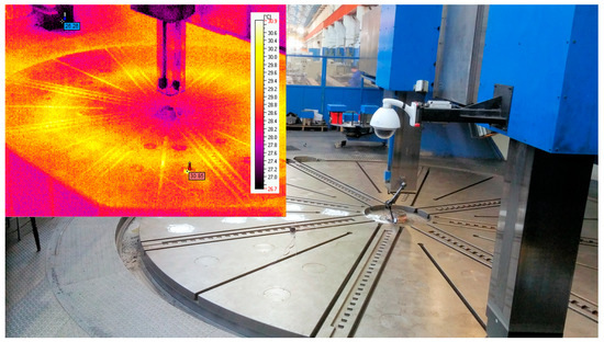
Figure 4.
Thermal deformation analysis of large-scale vertical lathe.
Geometrical measurements of the relative deformation of the table were performed using a contact method with analog Mitutoyo XQR dial gauges. These gauges, which hold valid calibration certificates, provide a measurement accuracy of 0.003 mm and a resolution of 0.001 mm.
3.1. Parametric Optimization
The parametric optimization methodology developed to solve the analyzed problem is schematically presented in Figure 5. The foundation of the computational model is the geometric model of the analyzed machine, which serves as the basis for creating the discrete parametric model in the finite element method (FEM) convention, along with the initialization parameters of the computational algorithm. Based on the discrete FEM model, a numerical computation block controlled by the optimization algorithm is executed iteratively.
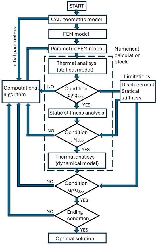
Figure 5.
Parametric optimization flowchart.
- First Iteration—Thermal State Analysis:
- A steady-state thermal analysis is conducted, which is independent of time.
- The use of a static thermal model accelerates calculations by eliminating transient effects.
- The steady-state condition is determined by analyzing results from the dynamic thermal model.
- Heat source power compensation is applied to account for the load from the lathe table’s self-weight.
- The algorithm determines the heat source components based on analytical relationships that depend on the table mass.
- Second Iteration—Static Stiffness Analysis:
- The static stiffness of the machine tool is evaluated.
- After each iteration, the results are compared with predefined constraints.
- If the constraints are not satisfied, the parameter set is rejected, and the optimization algorithm selects a new set of initialization parameters.
- The automated numerical computation process repeats until all constraint conditions are satisfied.
- Final Verification—Dynamic Thermal Analysis:
- Once an acceptable solution is found, a time-dependent dynamic thermal analysis of the machine tool is conducted to verify the obtained parameters.
- If the solution meets acceptance criteria, it is considered optimal. Otherwise, the algorithm starts a new iteration.
- Dynamic analysis helps identify the best solution from the set of feasible solutions by minimizing mass while maintaining maximum allowable displacements and the required minimum stiffness.
If the algorithm fails to find a satisfactory solution within a specified number of iterations, it terminates. The stopping criterion for the optimization process depends on the type of computational algorithm used. The parametric optimization was first performed based on the table design proposed by the designer (Figure 6). The optimization focused solely on the thickness of the table’s walls and ribs. Therefore, the number of ribs and their placement were not considered in the optimization process. Additionally, the overall dimensions of the table were assumed to remain unchanged.
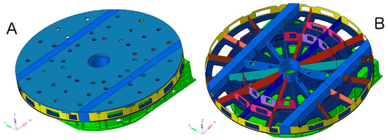
Figure 6.
Discrete model of the table with bed: (A) general view, (B) detailed view.
3.2. Optimization Models and Parameter Tuning
The optimization process employed three classes of algorithms: response surface and gradient-based methods, population-based metaheuristics (GA and PSO), and hybrid variants (hGA and hPSO) combining evolutionary optimization with metamodeling.
3.3. Response Surface and Gradient-Based Methods
For response surface method (RSM)-based and gradient-based algorithms, the optimization models integrated within HyperStudy were utilized with automatic parameter tuning relative to the problem configuration. Convergence was governed by standard termination criteria: negligible change in the solution point or objective function value, attainment of a predefined maximum number of iterations, and, in the case of gradient-based methods, satisfaction of the gradient stationarity condition.
When the solver encountered infeasible regions or failed analyses, the permissible methodologies of the ARSM, GRSM, and MFD algorithms were applied, involving a 50% reduction in the step size. For the SQP algorithm, failed line searches resulted in step-size halving, while failed gradient evaluations led to zero-gradient assignment. If convergence could not be achieved, the optimization process was terminated with a negative outcome.
These configurations ensured stable convergence while mitigating the impact of numerical instabilities and local infeasibility zones.
3.4. Genetic Algorithm (GA)
A built-in GA model from HyperStudy was employed, based on the canonical genetic algorithm framework. Parameter selection followed the empirical studies of Szczepanik [13], correlating algorithm efficiency with the number of decision variables. The adopted settings (Table 2) were selected to ensure a balance between convergence speed and population diversity.
Table 2.
Adopted GA parameters.
For both the basic (three-variable) and extended (fourteen-variable) models, crossover and mutation probabilities were adjusted to improve robustness against premature convergence. The GA typically achieved convergence within 40–60 generations, maintaining consistent search behavior across runs.
3.5. Particle Swarm Optimization (PSO)
The PSO algorithm was implemented through the HyperOpt interface of HyperStudy, allowing direct communication between the solver and an external MATLAB R2019a -based optimization engine. The implementation followed the formulations presented by Szczepanik [13] and the reference models developed by Heris [14].
Parameter tuning was performed based on empirical analysis, adjusting inertia and acceleration coefficients depending on the number of decision variables to improve convergence rate and prevent oscillations. The adopted PSO parameters are summarized in Table 3.
Table 3.
Decision variables of parametric optimization; PSO algorithm.
Convergence was defined by negligible improvements in the objective function or design vector, or by reaching the maximum iteration limit. For both tested configurations, the PSO algorithm exhibited stable convergence behavior, with the extended model demonstrating a longer transient phase before achieving a steady global optimum.
3.6. Hybrid Algorithms (hGA, hPSO)
Hybrid algorithms combined evolutionary search (GA or PSO) with metamodel-based response approximation, allowing accelerated convergence through reduced solver evaluations. The hybrid model generated an approximated parameter matrix based on bidirectional sampling within predefined bounds, followed by numerical evaluations using the finite element (FE) model.
The optimization algorithm then explored the reduced-order design space defined by the metamodel, and the resulting optimal parameters were validated using a dynamic thermal FE simulation. Due to inherent approximation errors, final verification was essential. The hybrid method proved effective for the extended model with fourteen design variables, achieving a reduction in computational cost of approximately 30–40% while maintaining comparable solution accuracy.
In the optimization model, the possibility of adjusting the thickness of different rib groups was considered, while maintaining their axial symmetry relative to the table. Accordingly, appropriate rib groups were selected. The ribs were divided into 14 groups, each corresponding to different decision variable parameters. The parametric model of the ribs is shown in Figure 7.
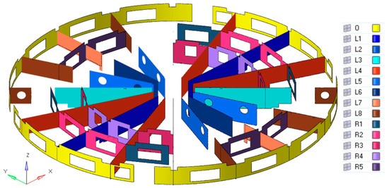
Figure 7.
Parametric model of table ribbing.
The decision variables for the parametric optimization of the topological model are presented in Table 4. In the model, topology modifications through the removal of ribs were not allowed, even if the optimization algorithm resulted in rib thickness values close to zero. The different colors of the FEM surface elements visible in the model represent various parameters that define the rib structure.
Table 4.
Decision variables of parametric optimization; hGA, hPSO algorithms.
The summary of results obtained using different optimization algorithms for the expanded model is presented in Table 5. The optimized mass remains within the acceptable limit of 105% of the initial mass. As a result of the optimization, the table displacement at point B was reduced to 0.5 mm. However, for point C, no significant change was observed compared to the initial model, while the displacement at point A increased by 0.01 mm, reaching 0.07 mm.
Table 5.
Summary of results obtained for different algorithms for the extended model.
The displacement map of the table’s working surface (Figure 8) reveals an asymmetry in the Z-axis displacement on one side of the table. This discrepancy may be due to the axial asymmetry of the table, arising from assembly connections or bed deformation. Due to technological constraints in casting production, all algorithm-derived values were rounded to 1 mm.
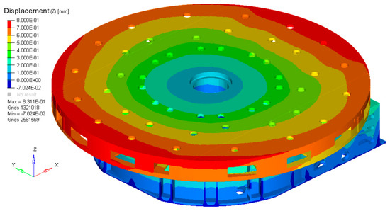
Figure 8.
Table and bed displacement map in Z axis.
For the obtained parameters, graphical heat distribution maps on the table’s working surface (Figure 9) are presented for the steady-state thermal condition after t = 300 min. Additionally, the displacement map in the Z direction after the same duration is shown in Figure 8. The most relevant results in the tabular summary are those from the GA (Genetic Algorithm) and PSO (Particle Swarm Optimization) algorithm, along with their hybrid versions. The optimized thickness parameters for the table ribs and walls of the carousel lathe based on the expanded model are provided in Table 5. The modifications introduced compared to the original (initial) model led to a 4% increase in the optimized table’s mass due to rib thickness adjustments.
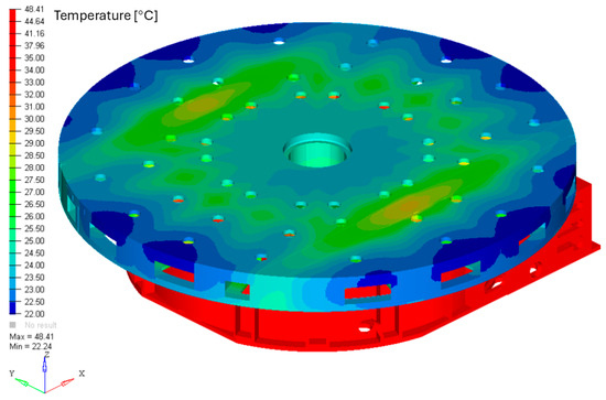
Figure 9.
Temperature distribution on the table working surface.
The ARSM, GRSM, SQP, and MFD algorithms failed to find an optimal solution. In the case of gradient-free algorithms, both SQP and MFD did not reach a feasible solution within 1000 iterations, resulting in premature termination. The gradient-based algorithms were stopped due to stationarity of the gradient condition, with ARSM terminating after 274 function evaluations and GRSM after 307 evaluations.
The best performance in terms of the lowest number of function evaluations was achieved by hybrid algorithms. Particle swarm-based algorithms demonstrated the highest efficiency, even when compared to genetic algorithms (GAs). Among the hybrid models combining GA and PSO with a gradient-based search method, the hPSO algorithm proved to be the most efficient, due to the superior effectiveness of the PSO-based search strategy.
3.7. Topological Optimization
The conducted optimization process is based on the SIMP (Solid Isotropic Microstructure with Penalization) method. The choice of this method was made based on a literature review regarding the effectiveness of topological optimization algorithms. The problem of topological optimization using GSO methods is widely discussed in [15,16,17,18,19,20], where the high effectiveness of SIMP has been demonstrated. Additionally, a detailed methodological description and proof of its superior performance compared to other material, geometric, and evolutionary algorithms were presented by Kalpakjian in [21]. Based on prior experience in topology optimization using various methods [22,23,24,25], the high efficiency of this algorithm was also confirmed.
To solve the analyzed problem, an extended version of the SIMP method was applied, incorporating a material addition process in highly stressed areas. Based on the defined task, following an approach analogous to the parametric optimization methodology presented in the diagram (Figure 5) and using FEM, the problem was divided into three sub-optimization tasks. The first task concerns the thermal model of the machine, the second addresses the time-dependent dynamic model, considering the table’s rotational speed, and the third focuses on static stiffness.
All optimization models operate based on the SIMP method, differing in the criteria used for material removal from the initial finite continuum Ω. In general terms, based on FEM analysis results, the SIMP algorithm iteratively removes material from the discretized domain Ω, consisting of finite elements, according to the adopted criterion.
For thermal analysis, the algorithm removes finite elements with displacements u smaller than the allowable displacements for a given step, udop + p, where p represents the iterative displacement increment until the boundary displacement is established. The solution is accepted only if the allowable displacement specified in the constraints is not exceeded.
In the case of the dynamic model of table rotation, the analysis constraint is the table’s resistance to the centrifugal force acting during its rotation. The algorithm for dynamic analysis removes finite elements from Ω where stresses s are lower than the allowable stresses for a given step, sdop + p, where p represents the iterative stress increment until the boundary stress is established.
For static stiffness, the algorithm eliminates finite elements from Ω with displacements u smaller than the allowable displacements for a given step, udop + p, where p represents the iterative displacement increment until the boundary displacement is established, similar to the thermal analysis.
All three subproblems of topology optimization are executed independently, based on the initial finite continuum model Ω. In each case, the algorithm selects the last iteration before exceeding the constraints or after reaching a predefined level of input mass reduction. The results obtained from the three independent processes are then superimposed, resulting in a discrete model that combines all input variants.
In the second part of the process, the obtained solution is verified and re-optimized to add material in highly stressed areas.
The model with the supplemented material is verified using the FEM according to the analysis cases defined in the first phase of optimization. After verification, the topology is either accepted or the material addition procedure is repeated until the structure meets the imposed constraints. The result of the optimization is a discretized model of the obtained structure in the form of a 3D finite element mesh, following the FEM convention.
According to the recommendations presented in [19], a safety factor of 1.5 was adopted for stresses, along with an allowable increase in table rotation speed up to 75 rpm. The load value for determining static stiffness was not increased, as the limiting condition requires that the minimum static stiffness of the optimized model should not be lower than that of the initial machine model. The developed methodology is presented in the form of a block diagram in Figure 10. As a result of the topology optimization based on the simple table (Figure 11), a discretized model of the central part of the table was obtained, as shown in Figure 12.
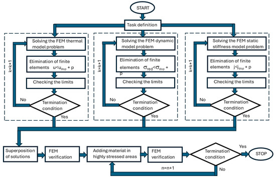
Figure 10.
Block diagram of topological optimization.
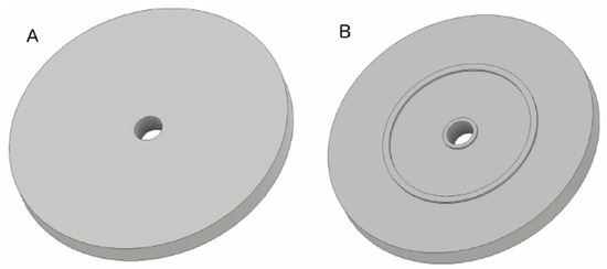
Figure 11.
Simplified batch model of the topological optimization table: (A)—top view, (B)—bottom view.
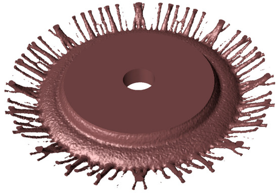
Figure 12.
Table interior after topological optimization (top view).
The resulting topology optimization model represents optimal energy flow paths and does not take manufacturing constraints into account; therefore, it requires refinement to remove erroneous elements and adaptation to manufacturing technology. Furthermore, despite the SIMP algorithm’s resistance to elements with zero or negative material density, it is necessary to verify the obtained model for their presence.
Based on the results of shape optimization and the determined energy flow paths, which correspond to the table’s ribbing topology, a CAD model of the structure was developed. Manufacturing aspects and design recommendations were taken into account. Compared to the topology model, the parametric model has a reduced number of ribs, as closely spaced thin ribs with a thickness not exceeding 25 mm were merged to form a rib with a thickness equal to the sum of the original rib thicknesses. Additionally, a full ribbing structure was introduced without cutouts and holes. Internal spaces with zero material density were filled with material.
The model was subjected to parametric optimization, where rib and table wall thicknesses were taken as decision variables, following the methodology. The parametric discrete model is shown in Figure 13.
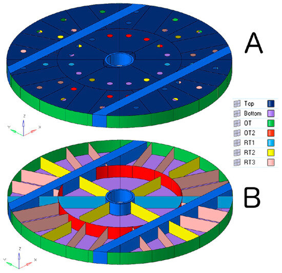
Figure 13.
Parametric model of the table ribbing after parametric optimization (A)—external view; (B)—ribbing view.
4. Parametric Optimization of the Obtained Topology
The initial values for the rib thicknesses were taken as average values from the rib profiles of the model obtained through topology optimization. For the working surface, table base, and side wall, no modifications were made in the topology optimization, so the initial thickness parameters were based on the machine’s original design documentation. The decision variables for the parametric optimization of the topology model are presented in Table 6. The parametric optimization of the topology model was carried out using the hybrid hPSO method. The results of the parametric optimization based on the topology obtained from topology optimization are shown in Table 7. The table compares the rib, wall, base, and working surface thicknesses for both the input model (topology from topology optimization) and the model after parametric optimization. The final thickness values were rounded to the nearest millimeter for technological reasons.
Table 6.
Decision variables for topological model parametric optimization.
Table 7.
The thickness of the walls and ribs of the table after the parametric optimization of the topological model.
This optimization allowed for further refinement of the structural elements to achieve a more efficient and manufacturable design while maintaining the necessary performance criteria.
5. Results of the Conducted Research
The displacement results for each model of the carousel lathe table obtained through parametric optimization, compared to the baseline model, are graphically presented in the form of charts in Figure 14. The displacement result at point B for the baseline model with 3 decision variables is 0.56 mm, representing a 15% reduction in displacement compared to the baseline model (0.66 mm). For the extended model with 14 decision variables, the displacement at point B was reduced to 0.5 mm after optimization. This result represents a 24% reduction in displacement relative to the baseline model (based on the original machine’s documentation). The percentage change in displacement at point B for different models, relative to the baseline model, is shown in Figure 15.
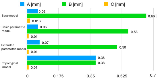
Figure 14.
Comparison of displacements at characteristic measuring points on the working surface of the table of the basic model and after optimization.
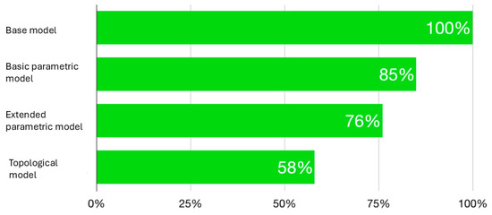
Figure 15.
Percentage change in displacement at point B for different models with respect to the base model.
A comparison of the mass of the carousel lathe table models obtained through parametric optimization, in comparison to the baseline model, is graphically presented in Figure 16. After optimization based on the baseline model, the table’s mass increased by 3% compared to the baseline model, which is within the acceptable limit set by the constraints. As a result of the changes introduced in the extended model optimization, the modification of rib thickness parameters caused a 4% increase in the mass of the optimized table compared to the original (input) model. The final mass of the table is within the acceptable range of 105% of the initial mass.
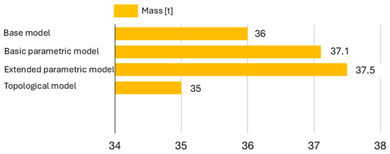
Figure 16.
Comparison of the weight of the base table and after optimization.
These results highlight the improvements in structural performance (displacement reduction) while maintaining the mass within acceptable limits. In addition to optimizing the rib and wall parameters of the table, the topology of the carousel lathe table was optimized using the extended SIMP method. As a result of the optimization, a discrete model in the FEM convention was obtained. Based on the obtained rib and wall trajectories of the table, a parametric model with 7 decision variables was created in the FEM convention. The model derived from the obtained topology of the table was subjected to parametric optimization using the best among the tested algorithms—the hybrid optimization algorithm hPSO.
On the displacement map of the table’s working surface, asymmetrical greater displacements in the Z-axis direction can be observed on one half of the table, which could be a consequence of axial asymmetry of the table resulting from its joining or deformation of the bed. The displacements measured at point B were reduced by 20% compared to the original model in the case of topology optimization alone, and by 43% in the case of topological–parametric optimization (Figure 14).
The achieved uniformity of displacements across the entire working surface of the table provides a basis for the implementation of active deformation compensation systems in machine tool bodies, which is an additional benefit arising from the introduced changes.
As a result of the optimization, the mass of the table was reduced to 35 tons, which is 1 ton lower than the original model (Figure 16) and 2.5 tons lower compared to the best solution after optimizing the rib and wall thicknesses of the original model.
An important aspect is that the displacement of the working surface of the table in the normal direction is uniform, with a deviation between the extreme measurement points A and B of just 0.01 mm.
6. Conclusions
Regarding the study’s research aim, which was to develop effective optimization methods for the rotary table to minimize thermal deformations, the following conclusions were drawn:
- The use of parametric optimization alone is recommended when modifying an existing structure. A reduction in thermal deformations of 15% was achieved for the baseline model and 24% for the extended model, corresponding to decreases in the maximum deformation (at point B) of 0.10 mm and 0.16 mm, respectively. Although this approach is economically justified, it restricts the design space to existing variants, which may deviate significantly from the global optimum.
- Topological optimization, as an alternative to parametric optimization, is economically justified only when developing a new design variant. In such cases, there is a high probability of finding a solution close to the global optimum. However, it should be noted that the obtained form must be adjusted to technological capabilities, and further parameter optimization of the resulting topology is recommended. A significant disadvantage of this approach is the risk of obtaining a variant that cannot be manufactured using commonly applied technologies.
- The results of this study demonstrate that the combined application of topological and parametric optimization is more effective than the use of parametric optimization alone. The topological–parametric optimization approach yielded a 43% reduction in thermal deformations, corresponding to a decrease of 0.28 mm in the maximum deformation.
- As observed from the comparison of the effectiveness and efficiency of solving the analyzed optimization task, the most effective algorithms among those tested are the hybrid algorithms, which combine gradient methods with particle swarm optimization (hPSO) (see Table 5).
Future research directions will focus, on one hand, on exploring solutions to the optimization problem using algorithms other than those proposed so far (e.g., differential evolution, surrogate-based optimization). On the other hand, a key aspect will be conducting verification studies in cases where the manufacturer implements the proposed design modifications.
Author Contributions
Conceptualization, M.W. and J.Ś.; methodology, M.W. and K.L.; software, K.L.; validation, J.Ś.; formal analysis, M.W., K.L. and J.Ś.; investigation, M.W. and K.L.; data curation, K.L.; writing—original draft preparation, M.W.; writing—review and editing, J.Ś. and K.L.; supervision, J.Ś. All authors have read and agreed to the published version of the manuscript.
Funding
This research received no external funding.
Institutional Review Board Statement
Not applicable.
Informed Consent Statement
Not applicable.
Data Availability Statement
The data presented in this study are available on request from the corresponding author.
Conflicts of Interest
The authors declare no conflicts of interest.
References
- Bryan, J.B. International Status of Thermal Error Research. CIRP Ann. Manuf. Technol. 1990, 39, 645–656. [Google Scholar] [CrossRef]
- Weck, M.; McKeown, P.; Bonse, R.; Herbst, U. Reduction and compensation of thermal errors in machine tools. CIRP Ann. 1995, 44, 589–598. [Google Scholar] [CrossRef]
- Srivastava, A.K.; Veldhuis, S.C.; Elbestawit, M.A. Modelling geometric and thermal errors in a five-axis CNC machine tool. Int. J. Mach. Tools Manuf. 1995, 35, 1321–1337. [Google Scholar] [CrossRef]
- Kim, J.J.; Jeong, Y.H.; Cho, D.W. Thermal behavior of a machine tool equipped with linear motors. Int. J. Mach. Tools Manuf. 2004, 44, 749–758. [Google Scholar] [CrossRef]
- Mu, S.; Yu, C.; Lin, K.; Lu, C.; Wang, X.; Wang, T.; Fu, G. A Review of Machine Learning-Based Thermal Error Modeling Methods for CNC Machine Tools. Machines 2025, 13, 153. [Google Scholar] [CrossRef]
- Ibaraki, S.; Okumura, R. A machining test to evaluate thermal influence on the kinematics of a five-axis machine tool. Int. J. Mach. Tools Manuf. 2021, 163, 103702. [Google Scholar] [CrossRef]
- Jiang, H.; Yang, F.; Wang, H.; Wang, S.; Fu, H. A Stiffener Structural Design Method for Worktable of Heavy-duty Vertical Lathe Combining Topology Optimization and Size Optimization. In Proceedings of the 6th International Conference on Mechanical, Automotive and Materials Engineering (CMAME), Hong Kong, China, 10–12 August 2018; IEEE Corporate Headquarters: New York, NY, USA, 2018; pp. 56–60. [Google Scholar] [CrossRef]
- Li, Y.; Zhao, W.; Lan, S.; Ni, J.; Wu, W.; Lu, B. A review on spindle thermal error compensation in machine tools. Int. J. Mach. Tools Manuf. 2015, 95, 20–38. [Google Scholar] [CrossRef]
- Li, Y.; Yu, M.; Bai, Y.; Hou, Z.; Wu, W. A Review of Thermal Error Modeling Methods for Machine Tools. Appl. Sci. 2021, 11, 5216. [Google Scholar] [CrossRef]
- Huang, B.; Xie, J.; Liu, X.; Yan, J.; Liu, K.; Yang, M. Vertical Machining Center Feed Axis Thermal Error Compensation Strategy. Res. Appl. Sci. 2023, 13, 2990. [Google Scholar] [CrossRef]
- Than, V.-T.; Ngo, T.-T.; Su, D.-Y.; Wang, C.-C. A study on thermal displacement of CNC horizontal lathe based on movable component temperatures. Aust. J. Mech. 2024, 22, 1–11. [Google Scholar] [CrossRef]
- Śliwka, J.; Wąsik, M.; Lis, K. Thermal deformations analysis of large-scale vertical lathe. Mech. Based Des. Struct. Mach. 2024, 52, 5133–5146. [Google Scholar] [CrossRef]
- Szczepanik, M. Algorytmy Rojowe w Optymalizacji Układów Mechanicznych; Wydawnictwo Politechniki Śląskiej: Gliwice, Poland, 2013. [Google Scholar]
- Heris, S. Implementation of Particle Swarm Optimization in MATLAB. Available online: http://yarpiz.com/391/ypap112-portfolio-optimization (accessed on 15 October 2025).
- Liu, H.; Qiu, Z.; Shi, J.; Sun, J.; Zhang, S. Ground structure method-based stiffener layout topology optimization for horizontal machining center headstock cover plate. Comput. Struct. 2025, 307, 107633. [Google Scholar] [CrossRef]
- Lin, S.-Y.; Chang, C.-H. Structure Design Improvement and Stiffness Reinforcement of a Machine Tool through Topology Optimization Based on Machining Characteristics. Appl. Sci. 2024, 14, 61. [Google Scholar] [CrossRef]
- Amr, A.E.; Rowan, E. Computational Design and Fabrication Strategy for Topology Optimization of Spiral Staircase Using Metal Wire Arc Additive Manufacturing. Nexus Netw. J. 2024, 26, 397–408. [Google Scholar] [CrossRef]
- Kostopoulos, C.; Marzok, A.; Waisman, H. Topology optimization of beams’ cross-sectional properties considering torsional and warping behavior. Struct. Multidiscip. Optim. 2025, 68, 28. [Google Scholar] [CrossRef]
- Zhang, W.; Zhuang, X.; Guo, X.; Youn, S.-K. Human-augmented topology optimization design with multi-framework intervention. Eng. Comput. 2025, 41, 2359–2376. [Google Scholar] [CrossRef]
- Qian, X.; Li, B.; Shen, Y.; Zhu, Q.; Tang, B.; Shi, Y.; Gao, C. Topological and stress optimizations of silicone layer in space solar Arrays. J. Polym. Res. 2025, 32, 57. [Google Scholar] [CrossRef]
- Kalpakjian, S.; Schmid, S. Manufacturing Engineering and Technology, 8th ed.; Pearson: London, UK, 2020; ISBN 10:1-292-42224-6. [Google Scholar]
- Sha, W.; Xiao, M.; Wang, Y.; Huang, M.; Li, Q.; Gao, L. Topology optimization methods for thermal metamaterials: A review. Int. J. Heat Mass Transf. 2024, 227, 125588. [Google Scholar] [CrossRef]
- Rong, J.-Q.; Rong, Y.; Liu, H.; Feng, X.-Q.; Zhao, Z.-L. Structural topology optimization method with adaptive support design. Adv. Eng. Softw. 2025, 201, 103830. [Google Scholar] [CrossRef]
- Cai, J.; Ding, H.; Huang, L. Topology optimization method of strut-and-tie composite structure under uncertain load conditions. Adv. Eng. Softw. 2025, 203, 103886. [Google Scholar] [CrossRef]
- Liu, X.; Gao, L.; Xiao, M. An efficient multiscale topology optimization method for frequency response minimization of cellular composites. Eng. Comput. 2025, 41, 267–291. [Google Scholar] [CrossRef]


Disclaimer/Publisher’s Note: The statements, opinions and data contained in all publications are solely those of the individual author(s) and contributor(s) and not of MDPI and/or the editor(s). MDPI and/or the editor(s) disclaim responsibility for any injury to people or property resulting from any ideas, methods, instructions or products referred to in the content. |
© 2025 by the authors. Licensee MDPI, Basel, Switzerland. This article is an open access article distributed under the terms and conditions of the Creative Commons Attribution (CC BY) license (https://creativecommons.org/licenses/by/4.0/).