Article

Design of a Six-Phase Surface Permanent-Magnet Synchronous Motor with Chamfer-Shaped Magnet to Reduce Cogging Torque and Torque Ripple for Large-Ship Propulsion

1
Department of Next Generation Smart Energy System Convergence, Gachon University, Seongnam 13120, Republic of Korea
2
Department of Electrical Engineering, Hanyang University, Seoul 04763, Republic of Korea
3
Department of Electrical Engineering, Gachon University, Seongnam 13120, Republic of Korea
4
Elmore Family School of Electrical and Computer Engineering, Purdue University, West Lafayette, IN 47907, USA
*
Author to whom correspondence should be addressed.
Appl. Sci. 2025, 15(21), 11400; https://doi.org/10.3390/app152111400 (registering DOI)
Submission received: 22 September 2025 / Revised: 7 October 2025 / Accepted: 22 October 2025 / Published: 24 October 2025

Abstract

Surface permanent-magnet synchronous motors (SPMSMs) have been widely adopted for ship propulsion due to their high power density and efficiency. However, conventional three-phase open-slot SPMSMs struggle to balance high efficiency with reductions in cogging torque and torque ripple. This paper proposes a design of an SPMSM with a six-phase winding configuration and a chamfer-shaped permanent magnet to reduce cogging torque and torque ripple. Electromagnetic performance is evaluated through finite element analysis (FEA). A reference three-phase interior PMSM and three-phase SPMSMs with different magnet shapes are first compared to identify a suitable basic design. Based on the basic machine, three pole–slot combinations for the six-phase winding are analyzed, and the most efficient configuration is selected. A final model is designed to minimize cogging torque and torque ripple for the chamfer-shaped permanent magnet. Finally, the effectiveness of the final model is validated through FEA by comparing its performance with that of the reference model.

1. Introduction

The 2023 IMO GHG Strategy tightened carbon-intensity targets to 40% by 2030 and 70% by 2050 (baseline 2008), requiring ship owners to comply with both the Energy-Efficiency Existing-ship Index (EEXI) and the Carbon Intensity Indicator (CII) rules [1]. Simultaneously, U.S.-flag vessels must meet MARPOL Annex VI Tier III NOx limits in designated Emission Control Areas, creating a dual CO2/NOx challenge. Studies indicate that slow steaming can cut annual CO2 emissions by roughly 32% without breaching new EEXI thresholds [1], while reactivity controlled compression ignition (RCCI) models predict NOx reductions of up to 45% at maintained efficiency [2]. However, onboard measurements often reveal higher CO2 factors than desk-based estimates [3], and variable-rate fuel injection struggles to meet Tier III at high load [4], underscoring the appeal of fully electric propulsion. Data-driven CII-prediction tools further indicate that electrification scenarios can improve a 2400 TEU container ship’s annual C-rating by an entire grade [5].
In large-ship propulsion applications, electrical machines are required for high efficiency, high power density, and high reliability [6,7,8]. Permanent magnet synchronous machines (PMSMs) with rare-earth magnets have attracted considerable attention for their superior efficiency and power density. Because large-ship propulsion involves operation at low speeds, surface PMSMs are widely used in large-ship propulsion applications due to their high performance [8,9,10]. To achieve high reliability, multi-phase electrical machines have been studied [11,12]. Specifically, six-phase winding, which involves dual three-phase winding, can operate through one inverter when a fault occurs in another inverter [11,13,14]. Furthermore, six-phase winding can reduce the torque ripple of SPMSMs through the phase shift of dual three-phase winding [15,16].
Because the slot-opening torque ripple of SPMSMs causes unacceptable vibration, acoustic noise, and poor control performance, designs to achieve torque ripple reduction have been studied; these have involved differing magnet pole arcs and ratios of slot width to slot pitch, as well as skewing [17,18,19,20,21,22,23,24]. In [17,18,19,20,21], a magnet shape design is proposed to reduce torque ripple through a sinusoidal-plus-third-harmonic shape, tapered shapes, and asymmetric designs. In [22,23,24], the skew method is employed to reduce torque ripple. However, this method poses challenges with regard to manufacturing and to achieving reductions in average torque. Alternatively, winding configurations to reduce torque ripple have been studied [25,26,27,28,29,30,31,32,33]. In [25,26,27,28,29,30,31], a fractional-slot configuration is proposed to reduce torque ripple. In [32,33], a multi-phase winding configuration is proposed to reduce torque ripple. Although this method can reduce electromagnetic torque ripple, it involves challenges in reducing cogging torque, which is determined by the magnet and stator shape. Achieving simultaneous reductions in cogging torque and torque ripple thus requires a combination of magnet shape design and winding configuration.
In this paper, a six-phase SPMSM with a chamfered magnet shape to reduce torque ripple is analyzed using finite element analysis (FEA). From a reference model, a three-phase interior PMSM (IPMSM), and a basic machine, a three-phase SPMSM, the winding configuration is converted from three-phase winding to asymmetric six-phase winding. For the asymmetric six-phase winding, the electromagnetic performance of various pole–slot combinations is investigated, and the superior pole–slot combination is selected. Based on the selected pole–slot combination, the chamfered magnet shape design is applied to minimize torque ripple and cogging torque. Results with respect to electromagnetic performance, including no-load and load characteristics, are compared to verify the effectiveness of the proposed design method. The final design model achieved a 28.49% reduction in cogging torque, a 1.19% reduction in torque ripple, and a 0.77% improvement in efficiency compared with the reference model, a three-phase IPMSM.
This paper is organized as follows: The characteristics of the six-phase SPMSM are analyzed in Section 2. In Section 3, the design of the six-phase SPMSM with chamfered magnet shape is proposed based on the three-phase machine. In Section 4, the performances of the reference and final models are compared to verify the effectiveness of the six-phase SPMSM with chamfered magnet shape. Section 5 gives the conclusions.

2. Characteristics of Six-Phase SPMSM for Large-Ship Propulsion

2.1. Machine Structure for Large-Ship Propulsion

Figure 1 presents a machine structure with integrated ventilation ducts for large-ship propulsion. For effective air cooling in high-power machines, the rotor is segmented into individual modules. This segmentation interrupts eddy current paths within the permanent magnets, thereby reducing associated losses, and permits separate machining and magnetization of each module, simplifying manufacturing. The motor can employ IPMSM or SPMSM. In SPMSM, a nonmagnetic protective sleeve encases each magnet to prevent separation under high centrifugal loads, as shown in Figure 1b. A rotor ventilation duct gap between modules guides cooling air from the inner magnet region to the housing, lowering thermal resistance and homogenizing temperature profiles without additional cooling systems. Interlocking laminations ensure structural integrity at high speed while providing defined radial airflow channels. Compared with liquid-cooled jackets, this air-cooled configuration adds negligible mass, preserving the power-to-weight ratio critical for ship propulsion applications.

2.2. Six-Phase Configuration

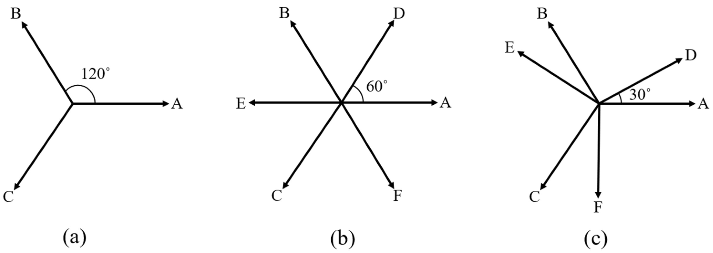
Figure 2a presents the conventional three-phase winding method. In a conventional three-phase system, the back electromotive force (BEMF) in each phase has a phase difference of 120°. There are two classifications of six-phase winding configuration: symmetric and asymmetric, as illustrated in Figure 2b and Figure 2c, respectively. The phase difference of each BEMF is 60° in symmetric six-phase winding, but the phase difference between the two three-phase groups (ABC and DEF), in which the phase difference is 120°, is 30° in asymmetric six-phase winding. Due to this characteristic of winding configuration, the BEMF can be expressed as follows:
(a)
BEMF of three-phase winding:
e A = n = o d d E n sin n ω e t , e B = n = o d d E n sin n ω e t 2 3 n π , e C = n = o d d E n sin n ω e t + 2 3 n π
(b)
BEMF of symmetric six-phase winding:
e A = n = o d d E n sin n ω e t , e B = n = o d d E n sin n ω e t 2 3 n π , e C = n = o d d E n sin n ω e t + 2 3 n π e D = n = o d d E n sin n ω e t n π 3 , e E = n = o d d E n sin n ω e t n π , e F = n = o d d E n sin n ω e t + n π 3
(c)
BEMF of asymmetric six-phase winding:
e A = n = o d d E n sin n ω e t , e B = n = o d d E n sin n ω e t 2 3 n π , e C = n = o d d E n sin n ω e t + 2 3 n π e D = n = o d d E n sin n ω e t n π 6 , e E = n = o d d E n sin n ω e t 5 6 n π , e F = n = o d d E n sin n ω e t + n π 2
where eA, eB, eC, eD, eE, and eF are the BEMFs of phases A, B, C, D, E, and F, respectively; En is the n-th harmonic component of the BEMF; n is the harmonic order; and ωe is the electrical speed.

2.3. Cogging Torque

Cogging torque originates from the discontinuity in magnetic flux between the permanent magnet and the stator slots in the absence of armature current. Because it represents the attractive force between the magnet and stator teeth, this effect is governed by variations in slot reluctance and permanent-magnet flux. The cogging torque can be expressed as follows:
T c o g ( θ ) = W m a g ( θ ) θ
where Tcog(θ) is the cogging torque, and Wmag(θ) is the magnetic storage energy. The magnetic storage energy is determined by the airgap magnetic flux density which is affected by the slot harmonic, and the magnetic flux density which is affected by the permanent magnet. The magnetic storage energy can therefore be expressed as a Fourier series, as shown in Equation (5).
W m a g ( θ ) = W 0 n = 1 W n cos n N c o g θ + ϕ n
where W0 is the DC component of magnetic storage energy, Wn is the harmonic component of magnetic storage energy, Ncog is the fundamental harmonic order of magnetic storage energy, and ϕ is the phase angle of magnetic storage energy. Because the magnetic storage energy is determined by the slot harmonic, and magnetic flux density by the permanent magnet, the fundamental harmonic order of magnetic storage energy is the least common multiple of the numbers of slots and poles. By substituting Equation (5) into Equation (4), the cogging torque can be expressed as follows:
T c o g ( θ ) = n = 1 n N c o g W n cos n N c o g θ + ϕ n
From Equation (6), cogging torque is determined by the flux density distribution and the slot/pole arrangement. The cogging torque coefficient Wn is governed by the interplay between slot count, pole count, and flux distribution. Slot asymmetry and mismatches between the numbers of slots and poles directly influence both the amplitude and harmonic order of the cogging torque.

2.4. Electromagnetic Torque

From the energy conversion principle, the electromagnetic torque can be expressed as follows:
T e = e k i k ω m
where Te is the electromagnetic torque; ek and ik are the BEMF and current, respectively, of phase k; and ωm is the mechanical speed. Assuming id = 0 control, the current of phase k can be expressed as follows:
(a)
Current of three-phase winding:
i A = I m sin ω e t , i B = I m sin ω e t 2 3 π , i C = I m sin ω e t + 2 3 π
(b)
Current of symmetric six-phase winding:
i A = I m sin ω e t , i B = I m sin ω e t 2 3 π , i C = I m sin ω e t + 2 3 π i D = I m sin ω e t π 3 , i E = I m sin ω e t π , i F = I m sin ω e t + π 3
(c)
Current of asymmetric six-phase winding:
i A = I m sin ω e t , i B = I m sin ω e t 2 3 π , i C = I m sin ω e t + 2 3 π i D = I m sin ω e t π 6 , i E = I m sin ω e t 5 6 π , i F = I m sin ω e t + π 2
where iA, iB, iC, iD, iE, and iF are the currents of each phase, and Im is the magnitude of current. Based on Equation (7), the electromagnetic torque for three-phase, symmetric six-phase, and asymmetric six-phase winding can be expressed as follows:
(a)
Electromagnetic torque of three-phase winding:
T e = T a v g + n = 1 T 6 n cos 6 n ω e t + ϕ n T a v g = 3 2 E 1 I m ω m ,   T 6 n = 3 2 E 6 n 1 E 6 n + 1 ω m
(b)
Electromagnetic torque of symmetric six-phase winding:
T e = T a v g + n = 1 T 6 n cos 6 n ω e t + ϕ n T a v g = 3 E 1 I m ω m ,   T 6 n = 3 E 6 n 1 E 6 n + 1 ω m
(c)
Electromagnetic torque of asymmetric six-phase winding:
T e = T a v g + n = 1 T 12 n cos 12 n ω e t + ϕ n T a v g = 3 E 1 I m ω m ,   T 12 n = 3 E 12 n 1 E 12 n + 1 ω m
From Equations (11) and (12), it may be seen that the torque ripple of three-phase winding and symmetric six-phase winding is primarily influenced by the (6n − 1)th and (6n + 1)th harmonic components of BEMF. However, the torque ripple of asymmetric six-phase winding is determined by the (12n − 1)th and (12n + 1)th harmonic components of BEMF because the phase difference eliminates the contribution of the (6n − 1)th and (6n + 1)th harmonic components of BEMF. As a result, the torque ripple of asymmetric six-phase winding can be lower than that of three-phase winding or symmetric six-phase winding. In the next section, a chamfer-shaped SPMSM with asymmetric six-phase winding is designed using FEA.

3. Design of Six-Phase SPMSM with Chamfered Magnet Shape

In this section, we investigate the electromagnetic performance of a three-phase SPMSM with different magnet shapes, including arc-shaped, arc-tapering-shaped, bread-shaped, and bread-tapering-shaped, to select a basic design. Based on the basic design, a six-phase SPMSM with a pole–slot combination and chamfered magnet shape is analyzed. Electromagnetic performance is evaluated based on FEA using ANSYS Maxwell 2024R2.

3.1. Basic Design Specification

To implement the six-phase winding, a basic three-phase machine is selected through comparison of the reference model (IPMSM) and four shapes of SPMSM, including arc-shaped, arc-tapering-shaped, bread-shaped, and bread-tapering-shaped, as illustrated in Figure 3. The specifications of these machines are summarized in Table 1. All models are designed with the same numbers of poles and slots, using a fractional-slot configuration to achieve low torque ripple. Their electromagnetic performances are compared using FEA, as shown in Table 2. To ensure comparability, total numbers of series turns and parallel circuits are the same for all models, so that they may be compared under the same conditions. Although the magnet total area is similar among the models, the no-load BEMF of SPMSM is higher than that of IPMSM, indicating greater torque capability. Under maximum torque per ampere (MTPA) control, the SPMSMs demonstrate superior performance compared with the reference IPMSM. While electromagnetic performance is comparable across different magnet shapes, the bread-shaped magnet is preferable from a manufacturing perspective, because both the magnet and core surfaces are flat. Therefore, the bread-shaped SPMSM is selected as the basic design for converting three-phase winding to six-phase winding.

3.2. Pole–Slot Combination for Six-Phase Winding

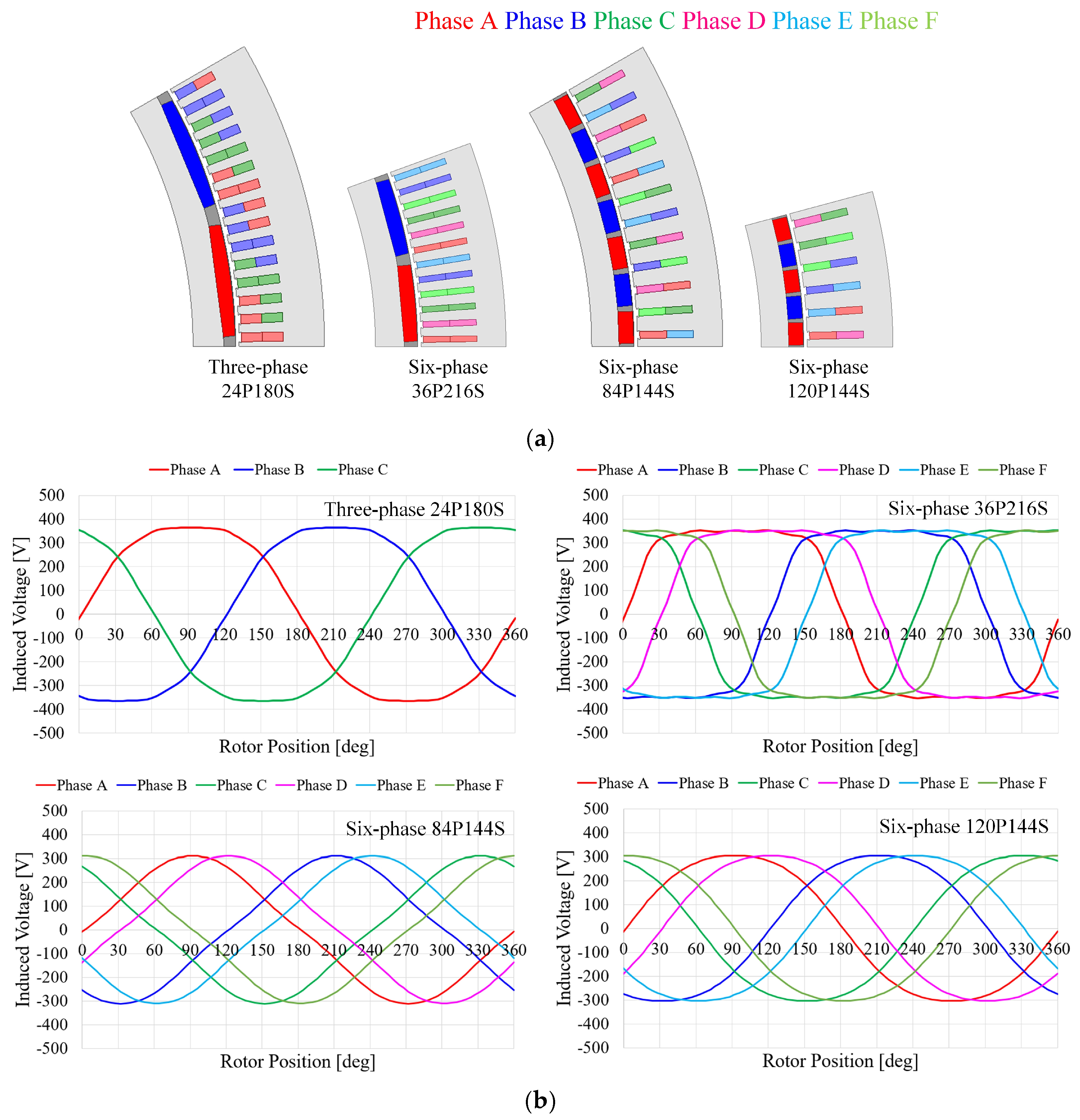
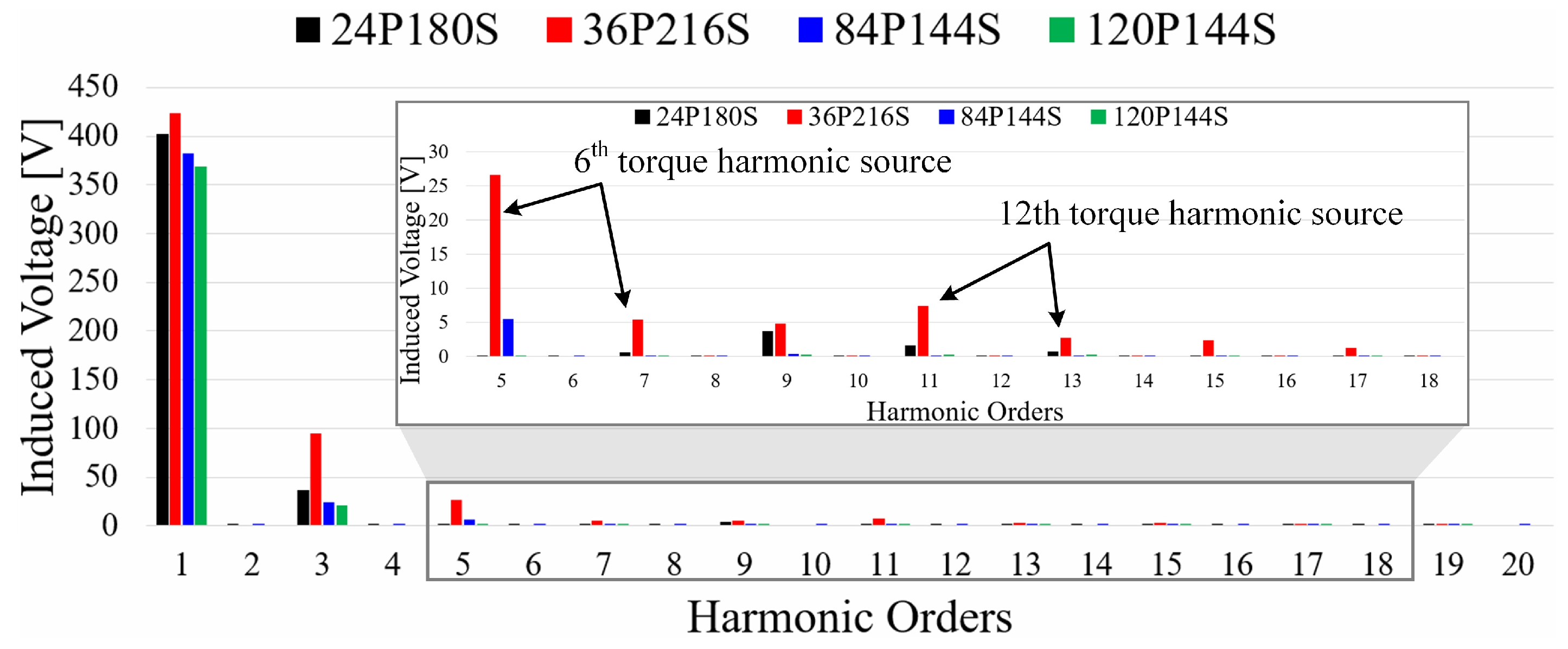
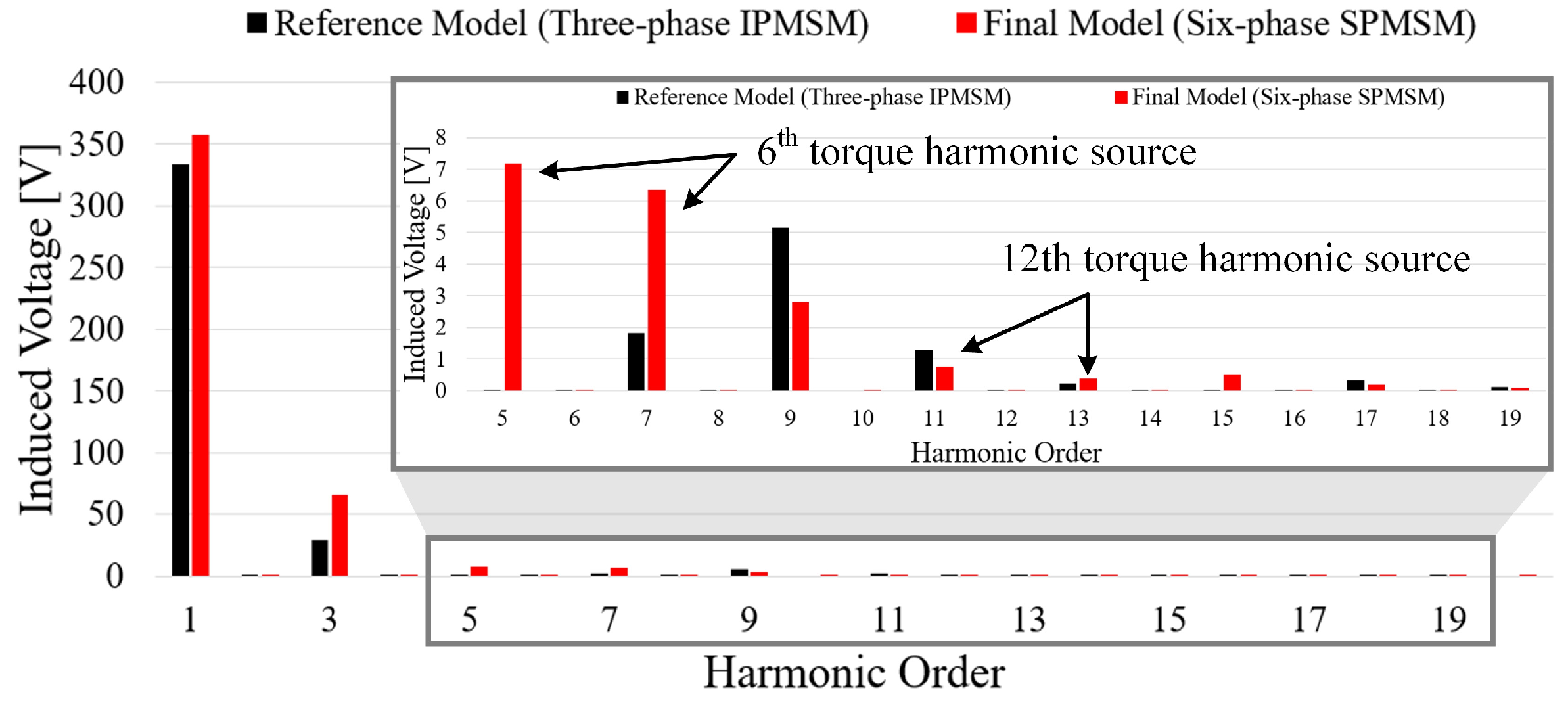
Based on the basic machine, which is the bread-shaped SPMSM, the pole–slot combination for six-phase winding is investigated. Three pole–slot combinations are selected for consideration of torque, as mentioned in Section 2.4; these are 36pole-216slot, 84pole-144slot, and 120pole-144slot, as illustrated in Figure 4a. For pole–slot combinations, the number of turns is designed to provide a similar no-load BEMF. In motor design, increasing the number of poles reduces the magnetic flux per pole, which decreases the stator yoke thickness but increases the leakage flux, thereby reducing the harmonic component of BEMF. As shown in Figure 4b, a higher pole count results in lower BEMF and a more sinusoidal waveform. Figure 5 shows the harmonic components of the no-load BEMF, obtained through Fast Fourier Transform (FFT) analysis. In the case of the high-pole machine, the harmonic component of BEMF is lower, compared to the other machines. However, the fundamental component of BEMF also decreases, which reduces the average torque. From Equations (11) and (13), the fifth and seventh BEMFs contribute to the sixth torque harmonic, while the eleventh and thirteenth BEMFs contribute to the twelfth torque harmonic. Although 36pole-216slot exhibits higher fifth and seventh harmonic components compared with the other models, these do not contribute the torque characteristics shown in Equation (13). Moreover, the average torque of this model is higher than those of the other models. Table 3 shows a comparison of the electromagnetic performances of the basic machine and the six-phase SPMSM with different pole–slot combinations. As the number of poles increases, iron loss, eddy current loss, and copper loss increase, leading to lower efficiency. Although 36pole-216slot has high torque per current and high efficiency, the torque ripple of this model is higher than that of other models due to the higher cogging torque. To reduce the torque ripple, a chamfered magnet shape design is introduced; this is discussed in the next section.

3.3. Chamfered Magnet Shape Design

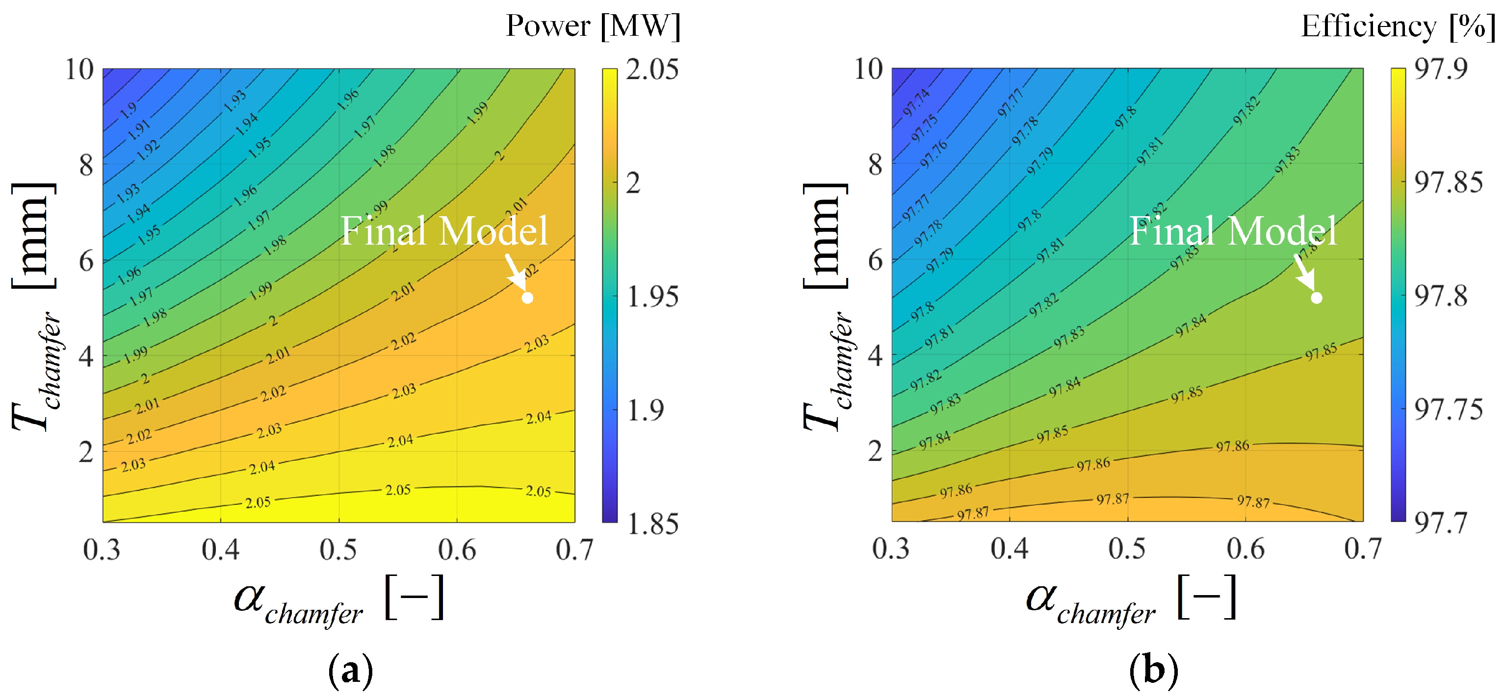
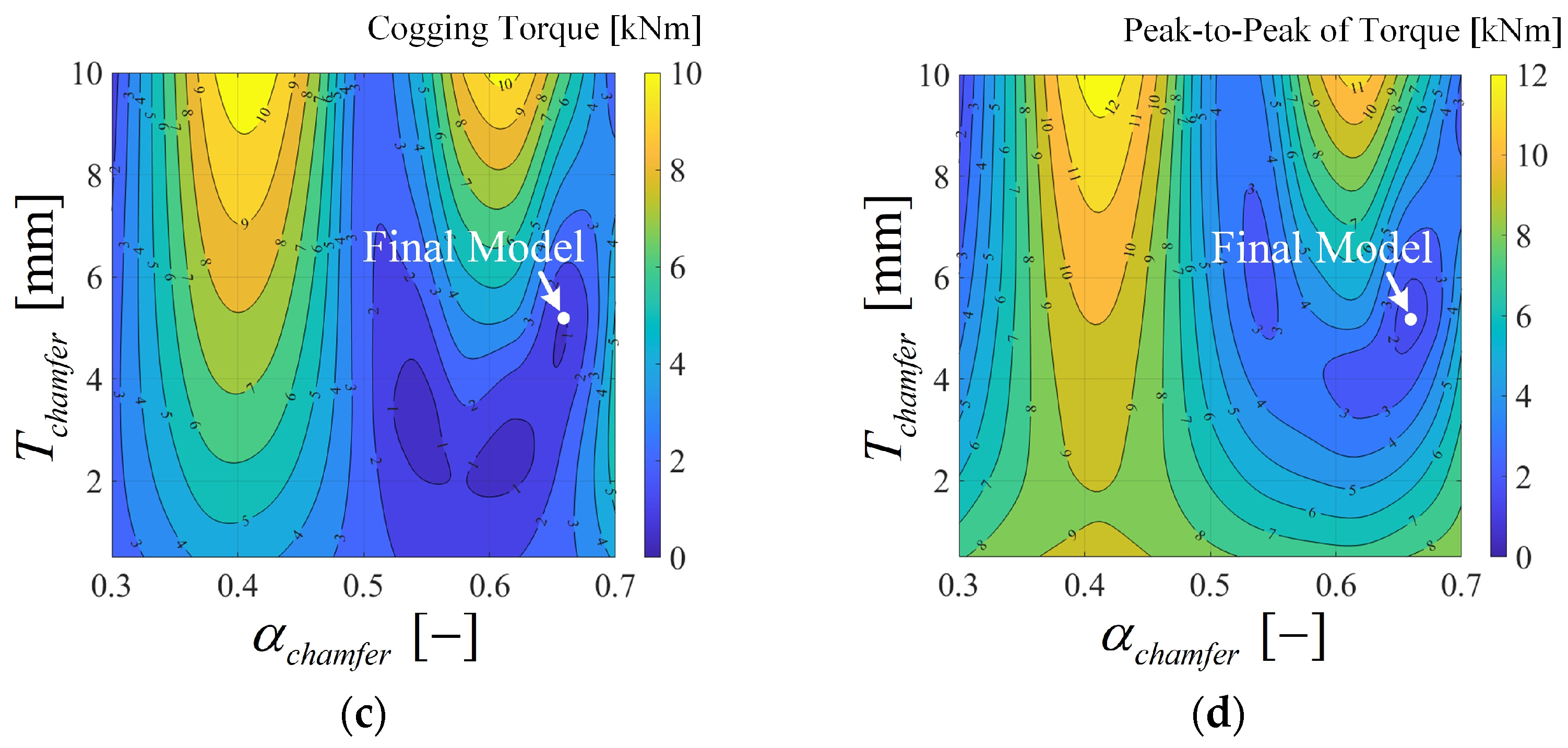
Although the 36poles-216slots machine with six-phase winding demonstrates superior performance, it suffers from high torque ripple caused by increased cogging torque. To address this issue, a chamfered magnet shape design is proposed. The design variables for the chamfered magnet shape are defined as chamfer shape thickness (Tchamfer) and chamfer ratio (αchamfer), as illustrated in Figure 6. The objective function of the design is to minimize cogging torque and torque ripple, and the constraints are the magnetic thickness and the magnet pole ratio, as shown in Figure 6. For the design variables, electromagnetic performance results, including power, efficiency, cogging torque, and torque ripple, are shown in Figure 7. The final model of the six-phase SPMSM is selected to minimize cogging torque and torque ripple. As a result, the design variables of the selected final model are 5.2mm of Tchamfer and 0.66 of αchamfer, and the final model is shown in Figure 8.

4. Performance Comparison

In this section, a performance comparison of the reference model (IPMSM) and the six-phase SPMSM final model is carried out for no-load and load characteristics. Through performance comparison, the effectiveness of the final model is validated.

4.1. No-Load Characteristics

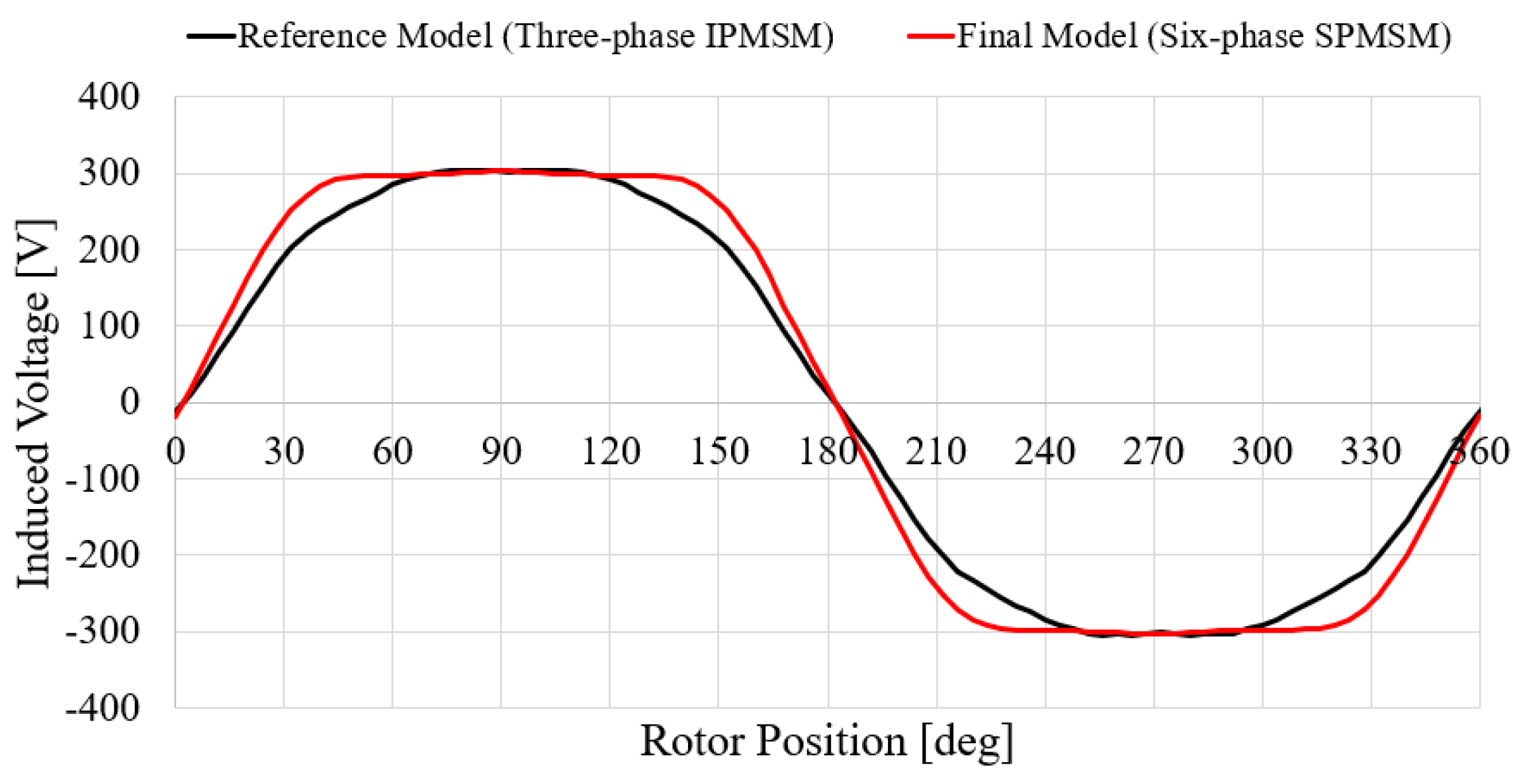
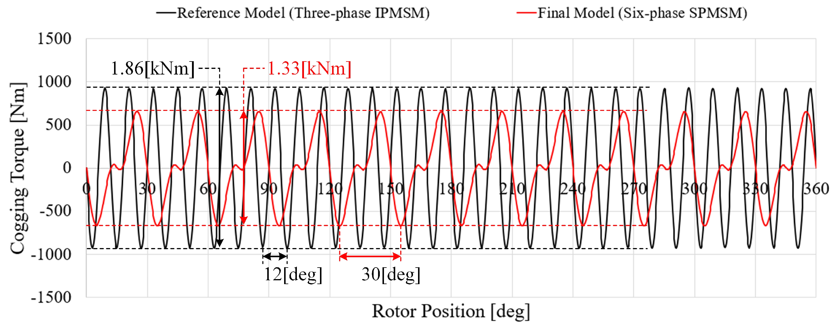
For the no-load characteristics, the no-load BEMF and the cogging torque of the reference and final model are compared. The waveform and FFT results of no-load BEMF for Phase A are shown in Figure 9 and Figure 10. As shown in Figure 9, the no-load BEMF of the reference model exhibits a more sinusoidal waveform than that of the final model. However, as shown in Figure 10, the fundamental component of the final model is higher than that of the reference model. Because the reference model has the more sinusoidal waveform, the harmonic component of the final model is higher than that of the reference model. Although the fifth and seventh harmonic components of the final model are higher than those of the reference model, they do not contribute torque ripple in the final model due to the asymmetric six-phase winding, as illustrated in Equation (13). By contrast, the fifth and seventh harmonic components of the reference model can contribute the sixth torque harmonic. Because the period of the cogging torque is the least common multiple of the numbers of poles and slots from Equation (6), the periods of the reference and final models are 12deg and 30deg, respectively, as shown in Figure 11. The cogging torque of the reference model is higher than that of the final model.

4.2. Load Characteristics

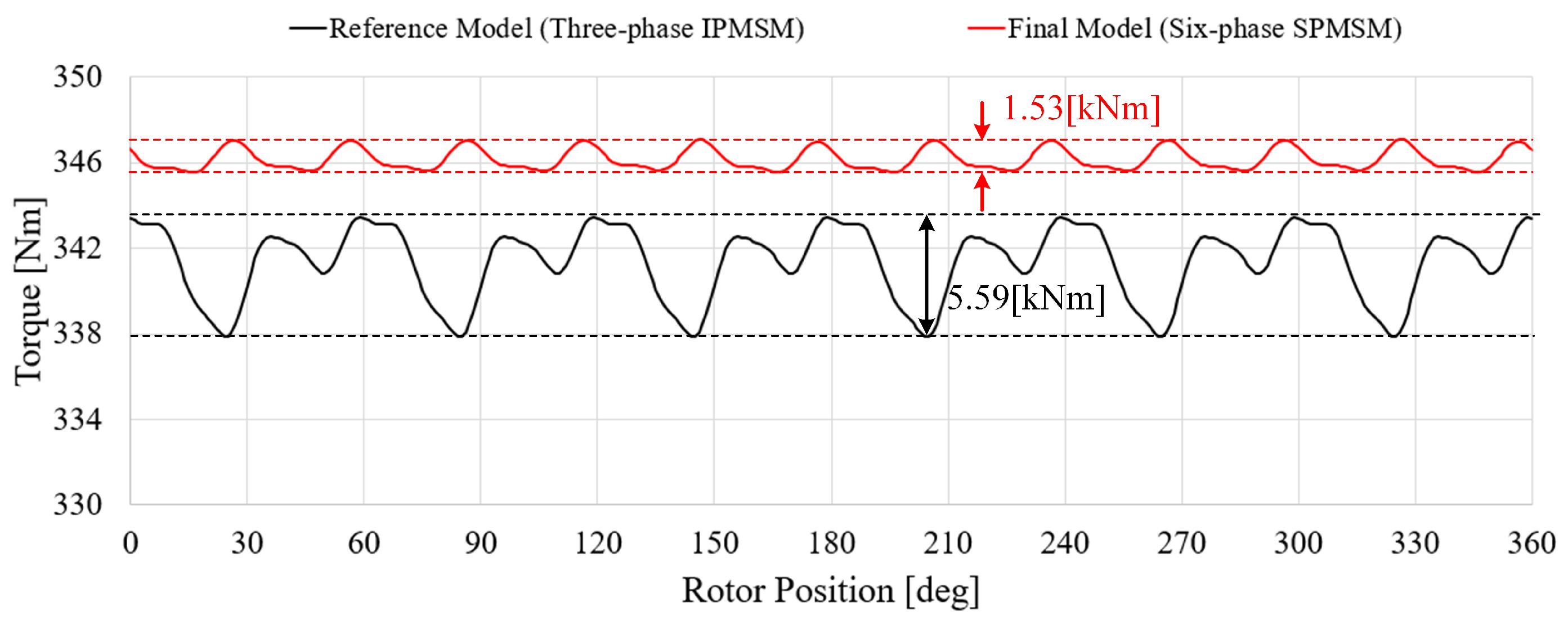
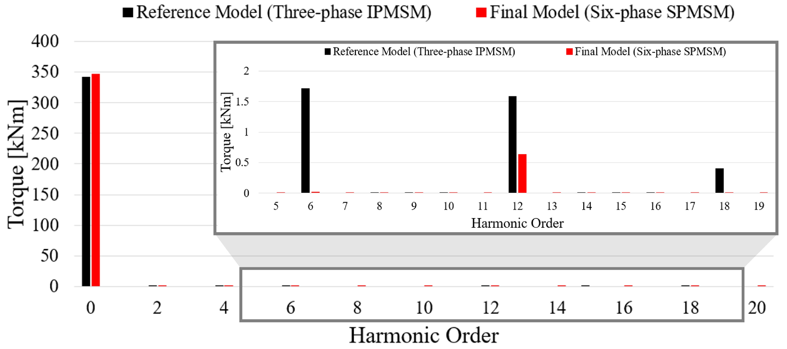
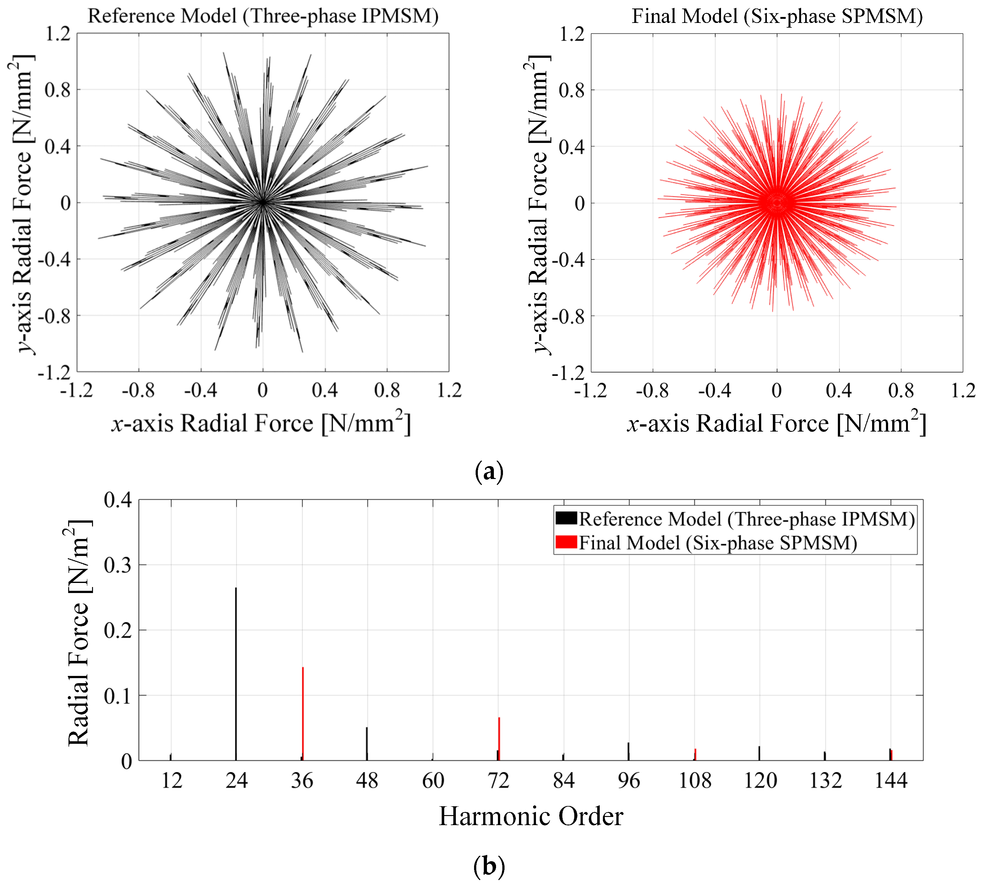
The load characteristics of the reference and final models are compared under the MTPA control. Because the average torque of the six-phase machine is doubled under the same BEMF and current conditions, the current magnitudes of the reference and final models are set to 2700 A and 1350 A, respectively. For these current magnitudes, the current phase angles of MTPA in the reference and final models are 15deg and 0deg, respectively. Figure 12 illustrates the torque waveforms of both models, showing that the peak-to-peak torque of the final model is reduced by approximately 72.63%. Furthermore, as shown in Figure 13, the dominant torque ripple orders in the reference and final models correspond to the sixth and twelfth harmonics, respectively. Figure 14 shows the radial forces of the reference and final models. The maximum radial force of the reference model is higher than that of the final model, as shown in Figure 14a. The radial force period is determined by the number of poles, as shown in Figure 14b. Since the reference and final models employ 24 and 36 poles, their fundamental radial forces are the 24th harmonic and 36th harmonic, respectively. The overall performances of the reference and final models are summarized in Table 4. It can be seen that the final model has better performance than the reference model, and that the effectiveness of the final model is validated through FEA results.

5. Conclusions

In this paper, an SPMSM with asymmetric six-phase winding and a chamfered magnet shape is proposed to mitigate cogging torque and torque ripple. Based on a reference model (three-phase IPMSM), a basic machine, a three-phase SPMSM, is designed and evaluated through FEA with different magnet shapes. From various pole and slot combinations, a 36poles-216slots model is selected, and a chamfered magnet shape design is applied to minimize cogging torque and torque ripple. The final model achieves 28.49% lower cogging torque, 1.19% lower torque ripple, and 0.77% higher efficiency, compared with the reference model. These results demonstrate the effectiveness of the proposed design in enhancing electromagnetic performance, including cogging torque, torque ripple, and efficiency. Future research will explore the applicability of this design method to machines of different sizes and extend the study to multi-physics analysis, including evaluations of electromagnetic, thermal, and structural factors, as well as noise, vibration, and harshness (NVH). Furthermore, experimental validation will be conducted through prototype fabrication and testing of the motor drive system.

Author Contributions

Conceptualization and design, W.-H.K. (including study concept, critical revision, and final approval); methodology development and data curation, D.-H.C. (including experimental design, data management, drafting the initial manuscript, and approval of the final version); software development and resource provision, H.-S.H. (including technical implementation, critical review, and final accountability for the software components); validation and overall research oversight, W.-H.K. (ensuring data integrity and accountability throughout the study); formal analysis and investigation, C.J. and H.-G.K. (performing comprehensive data analysis, interpretation, and figure visualization); writing—original draft preparation, D.-H.C. (responsibility for drafting the manuscript followed by critical revision by all authors); writing—review and editing, C.J., H.-S.H. and H.K. (providing in-depth manuscript reviews, revisions, and final manuscript approval); visualization, C.J., H.-G.K. and H.K. (developing data visualizations, ensuring clarity in presentation); supervision and project management, W.-H.K. (overseeing the entire research process and endorsing the final submission). All authors have read and agreed to the published version of the manuscript.

Funding

This research was supported by the Technology Innovation Program funded by the Ministry of Trade, Industry and Energy (MOTIE, Republic of Korea) (No. RS-2024-00441774), and was supported by a Korea Institute of Energy Technology Evaluation and Planning (KETEP) grant funded by the Korea government (MOTIE) (RS-2024-00419152, Development of 5 kW industrial logistics electric platform technology).

Institutional Review Board Statement

Not applicable.

Informed Consent Statement

Not applicable.

Data Availability Statement

The original contributions presented in the study are included in the article, further inquiries can be directed to the corresponding author.

Conflicts of Interest

The authors declare no conflicts of interest.

References

  1. Sjerić, M.; Tomić, R.; Martić, I.; Degiuli, N.; Grlj, C.G. Environmental and Economic Aspects of a Containership Engine Performance in Off-Design Conditions. Appl. Sci. 2024, 14, 4634. [Google Scholar] [CrossRef]
  2. Modabberian, A.; Storm, X.; Shamekhi, A.-M.; Vasudev, A.; Zenger, K.; Hyvönen, J.; Mikulski, M. Low Temperature Combustion Modeling and Predictive Control of Marine Engines. Appl. Sci. 2024, 14, 2033. [Google Scholar] [CrossRef]
  3. Lim, S.; Park, J.; Lee, J.; Lee, D.; Oh, J. Carbon Dioxide Emission Characteristics and Operation Condition Optimization for Slow-Speed and High-Speed Ship Engines. Appl. Sci. 2024, 14, 6134. [Google Scholar] [CrossRef]
  4. Chen, J.; Shi, G.; Wu, J.; Cao, C.; Zhou, L.; Xu, W.; Wang, S.; Li, X. Combustion and Emission Characteristics of a Diesel Engine with a Variable Injection Rate. Appl. Sci. 2024, 14, 4941. [Google Scholar] [CrossRef]
  5. Wang, Z.; Lu, T.; Han, Y.; Zhang, C.; Zeng, X.; Li, W. Improving Ship Fuel Consumption and Carbon Intensity Prediction Accuracy Based on a Long Short-Term Memory Model with Self-Attention Mechanism. Appl. Sci. 2024, 14, 8526. [Google Scholar] [CrossRef]
  6. Kim, H.; Park, Y.; Oh, S.-T.; Jin, C.-S.; Lee, J.; Kim, W.-H. Study on the Design of Six-Phase Surface Inset Permanent Magnet Synchronous Generator and Motor Considering the Power Factor and Torque Ripple. IEEE Trans. Magn. 2022, 58, 8202005. [Google Scholar] [CrossRef]
  7. Qiao, M.; Jiang, C.; Zhu, Y.; Li, G. Research on Design Method and Electromagnetic Vibration of Six-Phase Fractional-Slot Concentrated-Winding PM Motor Suitable for Ship Propulsion. IEEE Access 2016, 4, 8535–8543. [Google Scholar] [CrossRef]
  8. Arish, N.; Kamper, M.J.; Wang, R.-J. Design and Optimisation of a 5 MW Permanent Magnet Vernier Motor for Podded Ship Propulsion. World Electr. Veh. J. 2024, 15, 119. [Google Scholar] [CrossRef]
  9. Ojaghlu, P.; Vahedi, A. Specification and Design of Ring Winding Axial Flux Motor for Rim-Driven Thruster of Ship Electric Propulsion. IEEE Trans. Veh. Technol. 2019, 68, 1318–1326. [Google Scholar] [CrossRef]
  10. Karakatsanis, T.S. Optimization and Performance Evaluation of PM Motor and Induction Motor for Marine Propulsion Systems. Appl. Syst. Innov. 2025, 8, 58. [Google Scholar] [CrossRef]
  11. Demir, Y.; Aydin, M. A Novel Asymmetric and Unconventional Stator Winding Configuration and Placement for a Dual Three-Phase Surface PM Motor. IEEE Trans. Magn. 2017, 53, 8111805. [Google Scholar] [CrossRef]
  12. Shah, S.H.; Wang, X.; Azeem, M.; Abubakar, U. Evaluation of Magnetomotive Force and Torque Ripples in Modular Type IPMSM with Multi Three-Phase Winding Configurations. IEEE Access 2022, 10, 1577–1590. [Google Scholar] [CrossRef]
  13. Hu, Y.; Zhu, Z.Q.; Wu, Z.-y. Modelling and Vector Control of Dual Three-Phase PMSM with One-Phase Open. IET Electr. Power Appl. 2021, 15, 847–860. [Google Scholar] [CrossRef]
  14. Chen, L.; Chen, M.; Li, B.; Sun, X.; Jiang, F. Optimized Fault-Tolerant Control of Dual Three-Phase PMSM Under Open-Switch Faults. Energies 2024, 17, 5198. [Google Scholar] [CrossRef]
  15. Zhu, Z.; Wang, S.; Shao, B.; Yan, L.; Xu, P.; Ren, Y. Advances in Dual-Three-Phase Permanent Magnet Synchronous Machines and Control Techniques. Energies 2021, 14, 7508. [Google Scholar] [CrossRef]
  16. Han, X.; Jiang, D.; Zou, T.; Qu, R.; Yang, K. Two-Segment Three-Phase PMSM Drive with Carrier Phase-Shift PWM for Torque Ripple and Vibration Reduction. IEEE Trans. Power Electron. 2019, 34, 588–599. [Google Scholar] [CrossRef]
  17. Wu, D.; Zhu, Z.Q. Design Tradeoff between Cogging Torque and Torque Ripple in Fractional Slot Surface-Mounted Permanent Magnet Machines. IEEE Trans. Magn. 2015, 51, 8108704. [Google Scholar] [CrossRef]
  18. Islam, R.; Husain, I.; Fardoun, A.; McLaughlin, K. Permanent Magnet Synchronous Motor Magnet Designs with Skewing for Torque Ripple and Cogging Torque Reduction. In Proceedings of the 2007 IEEE Industry Applications Annual Meeting, New Orleans, LA, USA, 23–27 September 2007; pp. 1552–1559. [Google Scholar] [CrossRef]
  19. Tsunata, R.; Takemoto, M. Skewing Technology for Permanent Magnet Synchronous Motors: A Comprehensive Review and Recent Trends. IEEE Open J. Ind. Electron. Soc. 2024, 5, 1251–1273. [Google Scholar] [CrossRef]
  20. Du, Z.S.; Lipo, T.A. High Torque Density and Low Torque Ripple Shaped-Magnet Machines Using Sinusoidal Plus Third Harmonic Shaped Magnets. IEEE Trans. Ind. Appl. 2019, 55, 2601–2610. [Google Scholar] [CrossRef]
  21. Sun, Y.; Zhao, Z.; Zhang, Q. Design and Analysis of a Low Torque Ripple Permanent Magnet Synchronous Machine for Flywheel Energy Storage Systems. Energies 2024, 17, 6337. [Google Scholar] [CrossRef]
  22. Chu, W.Q.; Zhu, Z.Q. Reduction of On-Load Torque Ripples in Permanent Magnet Synchronous Machines by Improved Skewing. IEEE Trans. Magn. 2013, 49, 3822–3825. [Google Scholar] [CrossRef]
  23. Du, Z.S.; Lipo, T.A. Reducing Torque Ripple Using Axial Pole Shaping in Interior Permanent Magnet Machines. IEEE Trans. Ind. Appl. 2020, 56, 148–157. [Google Scholar] [CrossRef]
  24. Ocak, O.; Aydin, M. An Innovative Semi-FEA-Based, Variable Magnet-Step-Skew to Minimize Cogging Torque and Torque Pulsations in Permanent Magnet Synchronous Motors. IEEE Access 2020, 8, 210775–210783. [Google Scholar] [CrossRef]
  25. Sun, H.; Wang, K.; Zhu, S.; Liu, C. Performance Comparisons of Fractional Slot Surface-Mounted Permanent Magnet Machines with Slot-Harmonic-Only Windings. IEEE Trans. Energy Convers. 2021, 36, 995–1004. [Google Scholar] [CrossRef]
  26. Li, Y.; Zhu, Z.Q.; Li, G.J. Influence of Stator Topologies on Average Torque and Torque Ripple of Fractional-Slot SPM Machines with Fully Closed Slots. IEEE Trans. Ind. Appl. 2018, 54, 2151–2164. [Google Scholar] [CrossRef]
  27. Chen, J.; Yang, J.; Liu, W.; Yang, G.; Zhang, C. Effect of Flux Density Harmonics on Torque Characteristics of Integer Slot and Fractional Slot PMSMs. IEEE Trans. Energy Convers. 2025, 40, 2217–2226. [Google Scholar] [CrossRef]
  28. Jalali, P.; Boroujeni, S.T.; Khoshtarash, J. Expansion of the Feasible Slot/Pole Combinations in the Fractional Slot PM Machines by Applying Three-Slot Pitch Coils. IEEE Trans. Energy Convers. 2019, 34, 993–999. [Google Scholar] [CrossRef]
  29. Sun, X.; Zhu, Z.Q.; Cai, S.; Wang, L.; Wei, F.R.; Shao, B. Influence of Stator Slot and Rotor Pole Number Combination on Field Winding Induced Voltage Ripple in Hybrid Excitation Switched Flux Machine. IEEE Trans. Energy Convers. 2021, 36, 1245–1261. [Google Scholar] [CrossRef]
  30. Zhu, S.; Zhao, W.; Ji, J.; Liu, G.; Lee, C.H.T. Design to Reduce Modulated Vibration in Fractional-Slot Concentrated-Windings PM Machines Considering Slot–Pole Combination. IEEE Trans. Transport. Electrific. 2023, 9, 575–585. [Google Scholar] [CrossRef]
  31. Yu, Y.; Pei, Y.; Chai, F.; Doppelbauer, M. Analysis of Back EMF Harmonics Influenced by Slot–Pole Combinations in Permanent Magnet Vernier In-Wheel Motors. IEEE Trans. Ind. Electron. 2023, 70, 4461–4471. [Google Scholar] [CrossRef]
  32. Abdel-Khalik, A.S.; Ahmed, S.; Massoud, A.M. Low Space Harmonics Cancelation in Double-Layer Fractional Slot Winding Using Dual Multiphase Winding. IEEE Trans. Magn. 2015, 51, 8104710. [Google Scholar] [CrossRef]
  33. Wang, X.; Sala, G.; Zhang, H.; Gu, C.; Buticchi, G.; Formentini, A.; Gerada, C.; Wheeler, P. Torque Ripple Reduction in Sectored Multi Three-Phase Machines Based on PWM Carrier Phase Shift. IEEE Trans. Ind. Electron. 2020, 67, 4315–4325. [Google Scholar] [CrossRef]
  34. Son, R.-W.; Lee, J. Alternative Surface-Mounted Permanent Magnet Topology for Reducing Voltage and Torque Harmonics in Shaft Generators. Energies 2023, 16, 4649. [Google Scholar] [CrossRef]
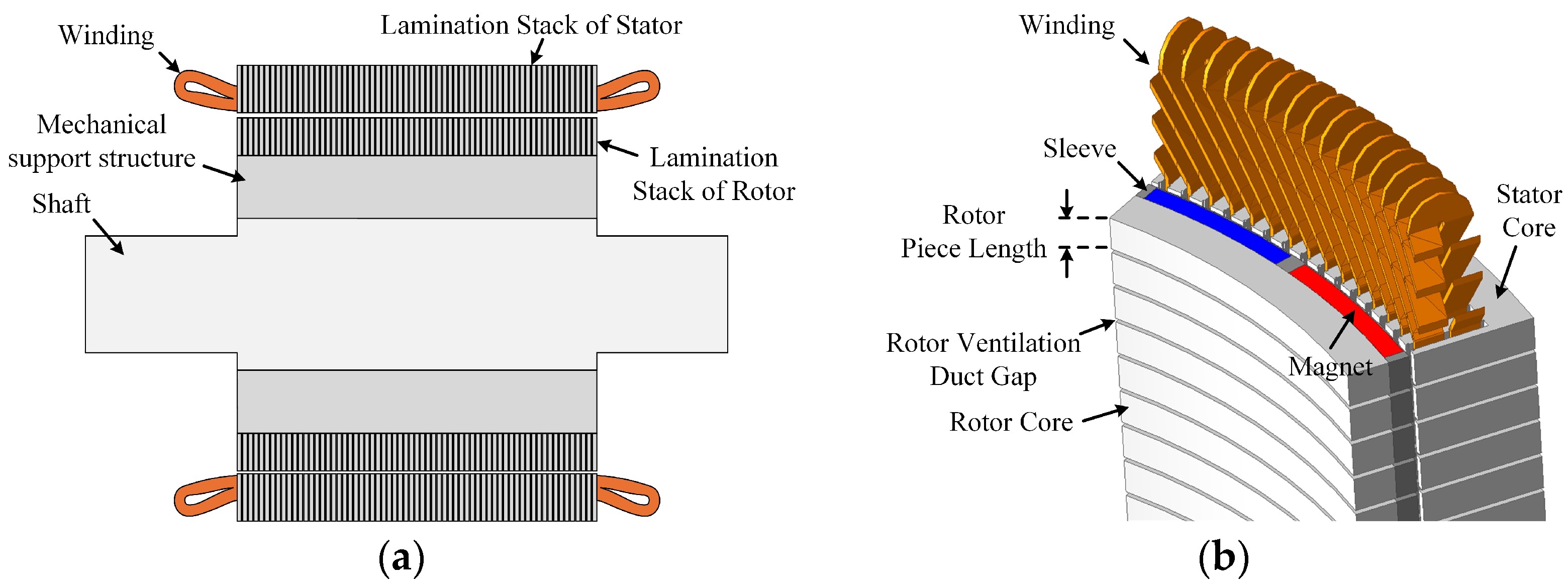
Figure 1. Machine structure for large-ship propulsion: (a) overall structure; (b) rotor.
Applsci 15 11400 g001
Figure 2. Three-phase and six-phase winding configurations: (a) three-phase; (b) symmetric six-phase; (c) asymmetric six-phase.
Applsci 15 11400 g002
Figure 3. Comparison models: (a) reference model (IPMSM); (b) arc-shaped SPMSM; (c) arc-tapering-shaped SPMCM; (d) bread-shaped SPMSM; (e) bread-tapering-shaped SPMSM [34].
Applsci 15 11400 g003
Figure 4. Comparison of basic machine and different pole-slot combination models for six-phase winding: (a) machine configuration; (b) no-load BEMF waveform.
Applsci 15 11400 g004
Figure 5. FFT induced voltage results for comparison models.
Applsci 15 11400 g005
Figure 6. Definitions of objective function, constraints, and design variables.
Applsci 15 11400 g006
Figure 7. Parametric analysis results for chamfered magnet shape design variables: (a) power; (b) efficiency; (c) cogging torque; (d) torque ripple.
Applsci 15 11400 g007aApplsci 15 11400 g007b
Figure 8. Final model of the six-phase SPMSM.
Applsci 15 11400 g008
Figure 9. Comparison of no-load BEMF waveforms of reference and final models.
Applsci 15 11400 g009
Figure 10. Comparison of no-load BEMF FFT results for reference and final models.
Applsci 15 11400 g010
Figure 11. Comparison of cogging torques of reference and final models.
Applsci 15 11400 g011
Figure 12. Comparison of torque waveforms of reference and final models.
Applsci 15 11400 g012
Figure 13. Comparison of torque FFT results of reference and final models.
Applsci 15 11400 g013
Figure 14. Comparison of radial forces of reference and final models: (a) radial force distribution; (b) FFT result.
Applsci 15 11400 g014
Table 1. Specifications of reference model.
ParameterValueUnit
Rated power2MW
Rated speed56rpm
Rated torque341kNm
MaximumThree-phase2850Arms
currentSix-phase1425Arms
Stator outer/inner diameter2450/2100mm
Rotor outer/inner diameter2086/1740mm
Stack length with/without ducts1210/1354mm
Airgap length7mm
Number of poles/slots24/180-
Rotor core material50PN600-
Stator core material50PN400-
Magnet materialN35UH-
Copper and magnet temperature80
Table 2. Comparison of electromagnetic performances of IPMSM and SPMSMs.
ParameterReference Model
(IPMSM)
SPMSMUnit
Arc-ShapedArc-Tapering-ShapedBread-ShapedBread-Tapering-Shaped
Total series turns3030303030-
Parallel circuit1212121212-
No-load BEMF236.75288.16274.19285.25267.93Vrms
Power2222.051.99MW
Torque341.33343.46341.78349.79340.15kNm
Torque ripple1.632.111.131.921.09%
Current27002380248524502530Arms
Copper loss54.842.5446.3845.0848.07kW
Eddy current loss0.0211.3114.89.9414kW
Iron loss5.54.84.414.834.34kW
Efficiency97.0797.1696.8297.1696.77%
Power factor80.7695.3894.3894.1392.86-
Magnet total area0.1670.1660.1640.1630.164m2
Table 3. Comparison of electromagnetic performances of three-phase SPMSM and six-phase SPMSM with different pole-slot combinations.
ParameterBasic MachineSix-PhaseUnit
36poles-216slots84poles-144slots120poles-144slots
Poles/slots24/18036/21684/144120/144-
Power2.052.062.092MW
No-load BEMF285.25306.7270.36260.61Vrms
Current2450116013551356Arms
Cogging torque2885.62500.524.6393.73Nm
Torque349.78352.45359.22345.04kNm
Torque ripple1.922.7416.2723.02%
Copper loss45.0834.2289.5468.1kW
Eddy current loss9.943.615.7627.86kW
Iron loss4.837.1162723.02kW
Efficiency97.1697.8794.594.73%
Table 4. Comparison of reference model and final model.
ParameterReference Model
(Three-Phase IPMSM)
Final Model
(Six-Phase SPMSM)
Unit
Pole/Slot24/18036/216-
Power22.02MW
Cogging Torque1.861.33kNm
No-load BEMF236.75257.86Vrms
Current27001350Arms
Power Factor80.7693.7%
Torque341.33346.16kNm
Torque Ripple1.630.44%
Copper Loss54.834.06kW
Eddy Current Loss0.023.79kW
Iron Loss5.56.81kW
Efficiency97.0797.84%
Total cost134.03124.46k$
Disclaimer/Publisher’s Note: The statements, opinions and data contained in all publications are solely those of the individual author(s) and contributor(s) and not of MDPI and/or the editor(s). MDPI and/or the editor(s) disclaim responsibility for any injury to people or property resulting from any ideas, methods, instructions or products referred to in the content.